US4732544A - Variable capacity wobble plate compressor - Google Patents
Variable capacity wobble plate compressor Download PDFInfo
- Publication number
- US4732544A US4732544A US07/058,288 US5828887A US4732544A US 4732544 A US4732544 A US 4732544A US 5828887 A US5828887 A US 5828887A US 4732544 A US4732544 A US 4732544A
- Authority
- US
- United States
- Prior art keywords
- movable member
- pressure
- spring
- discharge pressure
- wobble plate
- Prior art date
- Legal status (The legal status is an assumption and is not a legal conclusion. Google has not performed a legal analysis and makes no representation as to the accuracy of the status listed.)
- Expired - Lifetime
Links
Images


Classifications
-
- F—MECHANICAL ENGINEERING; LIGHTING; HEATING; WEAPONS; BLASTING
- F04—POSITIVE - DISPLACEMENT MACHINES FOR LIQUIDS; PUMPS FOR LIQUIDS OR ELASTIC FLUIDS
- F04B—POSITIVE-DISPLACEMENT MACHINES FOR LIQUIDS; PUMPS
- F04B27/00—Multi-cylinder pumps specially adapted for elastic fluids and characterised by number or arrangement of cylinders
- F04B27/08—Multi-cylinder pumps specially adapted for elastic fluids and characterised by number or arrangement of cylinders having cylinders coaxial with, or parallel or inclined to, main shaft axis
- F04B27/14—Control
- F04B27/16—Control of pumps with stationary cylinders
- F04B27/18—Control of pumps with stationary cylinders by varying the relative positions of a swash plate and a cylinder block
- F04B27/1804—Controlled by crankcase pressure
- F04B2027/1809—Controlled pressure
- F04B2027/1813—Crankcase pressure
-
- F—MECHANICAL ENGINEERING; LIGHTING; HEATING; WEAPONS; BLASTING
- F04—POSITIVE - DISPLACEMENT MACHINES FOR LIQUIDS; PUMPS FOR LIQUIDS OR ELASTIC FLUIDS
- F04B—POSITIVE-DISPLACEMENT MACHINES FOR LIQUIDS; PUMPS
- F04B27/00—Multi-cylinder pumps specially adapted for elastic fluids and characterised by number or arrangement of cylinders
- F04B27/08—Multi-cylinder pumps specially adapted for elastic fluids and characterised by number or arrangement of cylinders having cylinders coaxial with, or parallel or inclined to, main shaft axis
- F04B27/14—Control
- F04B27/16—Control of pumps with stationary cylinders
- F04B27/18—Control of pumps with stationary cylinders by varying the relative positions of a swash plate and a cylinder block
- F04B27/1804—Controlled by crankcase pressure
- F04B2027/1822—Valve-controlled fluid connection
- F04B2027/1831—Valve-controlled fluid connection between crankcase and suction chamber
-
- F—MECHANICAL ENGINEERING; LIGHTING; HEATING; WEAPONS; BLASTING
- F04—POSITIVE - DISPLACEMENT MACHINES FOR LIQUIDS; PUMPS FOR LIQUIDS OR ELASTIC FLUIDS
- F04B—POSITIVE-DISPLACEMENT MACHINES FOR LIQUIDS; PUMPS
- F04B27/00—Multi-cylinder pumps specially adapted for elastic fluids and characterised by number or arrangement of cylinders
- F04B27/08—Multi-cylinder pumps specially adapted for elastic fluids and characterised by number or arrangement of cylinders having cylinders coaxial with, or parallel or inclined to, main shaft axis
- F04B27/14—Control
- F04B27/16—Control of pumps with stationary cylinders
- F04B27/18—Control of pumps with stationary cylinders by varying the relative positions of a swash plate and a cylinder block
- F04B27/1804—Controlled by crankcase pressure
- F04B2027/184—Valve controlling parameter
- F04B2027/185—Discharge pressure
-
- F—MECHANICAL ENGINEERING; LIGHTING; HEATING; WEAPONS; BLASTING
- F04—POSITIVE - DISPLACEMENT MACHINES FOR LIQUIDS; PUMPS FOR LIQUIDS OR ELASTIC FLUIDS
- F04B—POSITIVE-DISPLACEMENT MACHINES FOR LIQUIDS; PUMPS
- F04B27/00—Multi-cylinder pumps specially adapted for elastic fluids and characterised by number or arrangement of cylinders
- F04B27/08—Multi-cylinder pumps specially adapted for elastic fluids and characterised by number or arrangement of cylinders having cylinders coaxial with, or parallel or inclined to, main shaft axis
- F04B27/14—Control
- F04B27/16—Control of pumps with stationary cylinders
- F04B27/18—Control of pumps with stationary cylinders by varying the relative positions of a swash plate and a cylinder block
- F04B27/1804—Controlled by crankcase pressure
- F04B2027/184—Valve controlling parameter
- F04B2027/1859—Suction pressure
Definitions
- This invention relates to a variable capacity wobble plate compressor for compressing refrigerant used in air conditioners for vehicles, etc.
- variable capacity wobble plate compressor which has such a construction that pressure in a crankcase in which a wobble plate is accomodated is regulated to adjust the inclination angle of the wobble plate, whereby the delivery quantity or capacity varies.
- This kind of conventional variable capacity wobble plate compressor is disclosed, for example, in Japanese Provisional Patent Publication (Kokai) No. 58-158382.
- the pressure in the crankcase where the wobble plate is provided is formed by pressure leaking through clearances between cylinders and pistons, i.e., blow-by gas pressure. Therefore, the pressure in the crankcase is higher than that in the suction chamber of the compressor during operation.
- a pressure-control valve provided across a communication passage between the crankcase and the suction chamber opens to allow the pressure in the crankcase (formed by blow-by gas) to flow into the suction chamber, whereby the pressure in the crankcase is lowered, accompanied by an increase in the inclination angle of the wobble plate.
- the increase in the inclination angle of the wobble plate causes a corresponding increase in the stroke of the piston, i.e., an increase in the delivery quantity or capacity.
- the thermal load is decreased (medium load state)
- the suction pressure is lowered
- the degree of opening of the pressure-control valve becomes smaller in accordance with the lowering of the suction pressure. This reduces the amount of pressure flowing from the crankcase into the suction chamber, which results in an increase in the pressure in the crankcase, accompanied by a decrease in the inclination angle of the wobble plate.
- This shortens the stroke of the piston, i.e., the capacity is decreased.
- the capacity of the compressor automatically varies with a change in the thermal load.
- the A.F. valve comprises a piston valve of a check valve type provided across a communication passage which communicates between the discharge pressure chamber and the crankcase.
- the A.F. valve does not open and is maintained in a closed state when the discharge pressure is in a region higher than a predetermined value.
- the A.F. valve opens and part of the pressure in the discharge pressure chamber is allowed to flow into the crankcase, which increases the pressure in the crankcase, accompanied by a decrease in the inclination angle of the wobble plate. This shortens the sroke of the piston, i.e., the capacity is reduced. The reduced capacity lessens the amount of refrigerant passing through the evaporator, which prevents the evaporator from being frozen.
- a variable capacity wobble plate compressor which includes: a crankcase; a wobble plate accomodated within the crankcase; a suction chamber; a communication passage communicating between the crankcase and the suction chamber; and a pressure-control valve disposed across the communication passage for adjusting pressure in the crankcase to change the inclination angle of the wobble plate whereby the delivery quantity or capacity is varied.
- the pressure-control valve comprises deformable means variable in length with a change in the suction pressure; a valve body attached to one end of the deformable means for selectively opening and closing the communication passage depending on the length of the deformable means; a first movable member attached to the other end of the deformable means; a first spring interposed between the valve body and the first movable member and urging the valve body in a closing direction; a second movable member having a pressure-receiving portion for receiving at least discharge pressure, said second movable member being selectively brought into and out of urging contact with the first movable member in response to at least a change in the discharge pressure acting upon the pressure-receiving portion; and a spring seat disposed in opposite and spaced relation to the pressure-receiving portion of the second movable member; and a second spring interposed between the spring seat and the second movable member.
- the second movable member When the discharge pressure is higher than a predetermined value, the second movable member is biased away from the first movable member by the discharge pressure against the force of the second spring, and when the discharge pressure is lower than the predetermined value, the second movable member is urged against the first movable member by the force of the second spring against the discharge pressure to urge the valve body in the closing direction via the first movable member, the first spring, and the deformable means.
- the pressure-receiving portion of the second movable member receives at one side surface thereof the discharge pressure and at another side surface thereof the suction pressure.
- the second movable member When the discharge pressure is higher than a predetermined value, the second movable member is biased away from the first movable member by the force of the discharge pressure against the sum of the force of the second spring and the suction pressure, and when the discharge pressure is lower than the predetermined value, the second movable member is urged against the first movable member by the sum of the force of the second spring and the suction pressure against the discharge pressure to urge the valve body in the closing direction via the first movable member, the first spring, and the deformable means.
- second deformable means variable in length with a change in the discharge pressure.
- the second movable member is attached to one end of the second deformable means, and the spring seat is attached to the other end of the second deformable means.
- the second movable member is urged against the first movable member by the force of the second spring against the force of the discharge pressure to urge the valve body in the closing direction via the first movable member, the first spring, and the first-mentioned deformable means.
- variable capacity wobble plate compressor of the present invention under such a condition that the discharge pressure lowers below such a predetermined value that the evaporator can be brought into a frozen state, the valve body is strongly urged in the closing direction by a substantially enhanced force due to the force of the second spring to thereby increase the force that urges the valve body in the closing direction, or the keeps same in the closing position, i.e. the valve opening pressure so that the pressure in the crankcase is accordingly elevated to decrease the inclination angle of the wobble plate.
- This causes a decrease in the delivery quantity or capacity, which, in turn decreases the amount of refrigerant passing through the evaporator, preventing the evaporator from being frozen.
- FIG. 1 is a longitudinal cross-sectional view of a variable capacity wobble plate compressor of the present invention
- FIG. 2 is an enlarged fragmentary view of a portion A in FIG. 1 which illustrates a pressure-control valve of a first embodiment of the present invention
- FIG. 3 is another enlarged fragmentary view of the portion A of FIG. 1 which illustrates a pressure-control valve of a second embodiment of the present invention.
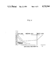
- FIG. 4 is a graph illustrating a pressure-control characteristic of the pressure-control valve of the compressor of the present invention.
- reference numeral 1 designates a housing of the compressor, which is formed of a cylinder block 2, a rear head 4 secured in airtight manner to a left end face of the cylinder block 2 as viewed in FIG. 1 through a valve plate 3, and a front head 5 secured in airtight manner to a right end face of the cylinder block 2.
- a crankcase 6 is defined within the interior of the housing 1 by an end face of the cylinder block 2 facing toward the front head 5, and inner peripheral walls and an inner end wall of the front head 5.
- a drive shaft 7 is arranged within the housing 1 and extends substantially along the axis of the housing.
- a plurality of cylinders 8 are formed in the cylinder block 2 in circumferentially equally spaced relation and extend with their respective axes parallel with the axis of the drive shaft 7, and in each of which is slidably fitted a piston 9.
- a discharge port 4a Formed in a left end face of the rear head 4 is a discharge port 4a through which compressed refrigerant gas is discharged.
- a discharge pressure chamber 10 which is divided into a first discharge pressure chamber 10 1 and a second discharge pressure chamber 10 2 by a partition wall 11.
- the first and second discharge chambers 10 1 and 10 2 communicate with each other through a restriction hole 11a provided in the partition wall.
- outlet ports 3a which are provided in the valve plate 3 communicate with the discharge port 4a via the first discharge pressure chamber 10 1 , the restriction hole 11a and the second discharge pressure chamber 10 2 , in the mentioned order.
- the outlet ports 3a are opened and closed by means of respective discharge valves 12.
- the discharge valves 12 are mounted on the valve plate 3 at a side surface thereof facing toward the rear head 4 together with retainers 13 by means of a set screw 14 which is threadedly fitted in a tapped hole 2a in the cylinder block 2 in a airtight manner through a hole 3c formed through the valve plate 3.
- a suction chamber 15 is formed around the discharge pressure chamber 10 in the rear head 4, which communicates with the cylinders 8 through respective inlet ports 3b formed through the valve plate 3.
- the inlet ports 3b are opened and closed by means of respective suction valves 15a, which are mounted on the valve plate 3 at a side surface thereof facing toward the cylinder block 2.
- the suction chamber 15 communicates with the outlet of an evaporator, not shown, of the air conditioning system through a suction port, not shown, while the discharge pressure chamber 10 communicates with the inlet of a condenser, not shown, of the air conditioning system, through the discharge port 4a.
- a valve chamber 16 is formed in the cylinder block 2, the valve plate 3, and the rear head 4.
- the valve chamber 16 communicates with the crankcase 6 via a communication passage 2b formed in the cylinder block 2.
- the valve chamber 16 also communicates with the suction chamber 15 via a hole 3d formed through the valve plate 3.
- Received within the valve chamber 16 is a pressure-control valve 17, which forms an essential portion of the compressor according to the present invention.
- the pressure-control valve 17 controls the pressure in the crankcase 6, and has a cylindrical casing 18 as shown in FIG. 2 illustrating a first embodiment of the present invention.
- the casing 18 is received within the valve chamber 16.
- One end face of the casing 18 is disposed in contact with an end face of a portion 16a of the valve chamber 16 located in the cylinder block 2 via a seat member 19.
- the casing 18 is fitted through a portion 16b of the valve chamber 16 located in the valve plate 3 in airtight manner by means of an O ring 20, with the other end being positioned in a portion 16c
- a space S is defined between an outer peripheral surface of the casing 18, and inner surfaces of the portion 16a of the valve chamber 16, and an end face of the valve plate 3.
- a peripheral surface 18a of one end of the casing 18 is tapered in a manner decreasing in diameter toward the one end face of the casing 18.
- a plurality of holes 18b are formed in the tapered surface 18a in circumferentially spaced relation.
- Formed through a central portion of the one end of the casing 18 is a valve hole 18c which is aligned and communicates with the communication passage 2b in the cylinder block 2 via a hole 19a formed through the seat member 19.
- the other end of the casing 18, which is open communicates with the second discharge pressure chamber 10 2 of the discharge pressure chamber 10 via a communication passage 21 formed in the rear head 4.
- a low pressure-operated portion 22 of the pressure-control valve 17 is disposed within a half portion of the casing 18 toward the one end thereof and a high pressure-operated portion of the presure-control valve 17 within the other half portion of the casing 18, respectively.
- the low pressure-operated portion 22 comprises bellows 24, a valve body 25 attached to one end (right end as viewed in FIG. 2) of the bellows 24, a first movable member 26 attached to the other end (left end as viewed in FIG. 2) of the bellows 24, a first spring 27 urging the valve body 25 in the closing direction.
- the bellows 24 is in the form of a hollow cylinder with opposite open ends and corrugated peripheral surfaces. The bellows is expandable and contractible in the longitudinal direction depending on the suction pressure Ps introduced through the hole 18b into the casing 18.
- the valve body 25 selectively opens and closes the communication passage 2b and comprises a valve main body 28 and a retaining member 29.
- the valve main body 28 has a tapered peripheral surface which decreases in diameter toward one end (right end as viewed in FIG. 2), and has the other end face formed integrally with a central projection 30.
- the projection 30 is force fitted in the retaining member 29 to combine the valve main body 28 and the retaining member 29 together, thus forming the valve body 25.
- the retaining member 29 comprises a hollow cylinder 31 which has opposite open ends and is formed integrally with an annular radial flange 32 at one end thereof (right end as viewed in FIG. 2).
- the valve body 25 is axially slidably disposed in one end portion of the casing 18.
- the first movable member 26 comprises a hollow cylinder which is open at one end (left end as viewed in FIG. 2) and closed at the other end and is formed integrally with an annular radial flange 34.
- the first movable member 26 is axially slidably disposed within the casing 18 in spaced opposite relation to the valve body 25.
- the bellows 24 is interposed between the opposed faces of the flange 32 of the valve body 25 and the flange 34 of the first movable member 26.
- the first spring 27 is in the form of a coil with one end thereof freely fitted on the hollow cylinder 31 of the valve body 25 and the other end thereof on the hollow cylinder 33 of the first movable member 26, respectively. Both ends of the first spring 27 are in urging contact with radially inner faces of the flanges 32 and 34, whereby the valve body 25 and the first movable member 26 are urged in directions away from each other.
- An annular partitioning wall 35 is fixed to an inner peripheral surface of the casing 18 at an axially intermediate location thereof and divides the casing 18 into two parts.
- the partitioning wall 35 determines the left extreme position of the first movable member 26 as viewed in FIG. 2. Further, the fixed position of the partitioning wall 35 decides the valve-opening pressure of the valve body 25.
- a hermetically closed space is defined by the bellows 24, the valve body 25 and the first movable member 26 and is vacuous in which is charged oil (not shown) in a volume of 70% to 80% of the whole volume of the space.
- the viscosity of the oil in the corrugated peripheral wall of the bellows 24 gives a "damping effect" to the bellows 24 as it expands or contracts upon rapid opening or closing of the valve body 25.
- the high pressure-operated portion 23 comprises a second movable member 37, a movable spring seat 38, and a second spring 39 which urges the second movable member 37 toward the first movable member 26.
- the second movable member 37 comprises an urging member 40 and a pressure-receiving member 41.
- the urging member 40 is in the form of a hollow cylinder with opposite open ends.
- the urging member 40 is axially movable so that one end (right end as viewed in FIG. 2) of the member 40 is brought into or out of contact with the first movable member 26 through a central hole 35a in the partitioning wall 35 through which the member 40 is airtightly fitted.
- the pressure-receiving member 41 is in the form of an annular plate formed centrally with a fitting hole 43, and is disposed to receive discharge pressure Pd at one end face (right end face as viewed in FIG. 2) and suction pressure Ps at the other end face (left end face as viewed in FIG. 2), respectively.
- An end portion of the urging member 40 is rigidly fitted in the fitting hole 43 whereby the urging member 40 and the pressure-receiving member are integrated with each other to form the second movable member 37.
- the movable spring seat 38 is in the form of a disc and is axially slidably disposed inside the casing 18 on the rear head side thereof in spaced and opposite relation to the second movable member 37.
- the second spring 39 is in the form of a coil, with one end thereof in urging contact with a radially outer portion of the pressure-receiving member 41 of the second movable member 37, and the other end thereof with with a radially outer portion of the movable spring seat 38, respectively. Accordingly, the second movable member 37 and the movable spring seat 38 are urged in directions away from each other by the second spring 39.
- Rigidly fitted in the casing 18 on the rear head side of the partitioning wall 35 is a cylindrical member 44 of which one end face (right end face as viewed in FIG. 2) is open and the other end face (left end face as viewed in FIG. 2) is closed.
- the one end face of the cylindrical member 44 is in contact with the partitioning wall 35, and the other end face forms a closed wall 45 through which is threadedly fitted an adjusting screw 46, which has an inner end face disposed in urging contact with a diametric center of the movable spring seat 38, to determine the left extreme position of the movable spring seat 38 as viewed in FIG. 2 (remote from the valve body).
- the setting load of the second spring 39 can be adjusted by the adjusting screw 46.
- the pressure-receiving member 41 of the second movable member 37 is slidably fitted in the cylindrical member 44 in airtight manner.
- the interior of the cylindrical member 44 communicates with the interior of the right-half portion of the casing 18 via a central hole 40a of the pressing member 40, whereby suction pressure Ps acts upon the other end surface of the pressure-receiving member. Further, a notch 40b is formed in one end face of the flange 34 of the first movable member 26, whereby even when the urging member 40 is in contact with the first movable member 26, communication is maintained between the central hole 40a and the interior of the right-half portion of the casing 18.
- the interior of the cylindrical member 44 communicates with the second discharge pressure chamber 10 2 of the discharge pressure chamber 10 via an axial hole 47 formed through the peripheral wall of the cylindrical member 44 and the communication passage 21 in the rear head 4.
- the casing 18 is urged by a wave-shaped spring 17a toward the right side as viewed in FIG. 2 (toward the seat member 19), whereby airtightness is maintained between the seat member 19 and the cylinder block 2 at a contacting portion 2c, and between the seat member 19 and the casing 18 at a contacting portion 18d, respectively, to prevent the refrigerant from leaking from the crankcase pressure Pw-prevailing side into the suction pressure Ps-prevailing side through the contacting portions 2c, 18d.
- the drive shaft 7 has an end portion toward the rear head 4 rotatably fitted in a central hole 48 in the cylinder block 2 via a bearing 49, while the other end portion toward the front head 5 is rotatably fitted in a central hole 50 in the front head 5 via a radial bearing 51.
- the end portion of the drive shaft 7 toward the front head 5 further extends through a projected portion of the front head 5 to the outside as an exterior extension with which a clutch, not shown, and a pulley, not shown, are connected.
- the pulley is connected, by a drive belt, not shown, with a pulley on an output shaft of an engine, not shown, which is installed on the vehicle, so that the rotation of the engine is transmitted to the drive shaft 7.
- a rotary retainer 53 is fitted around the drive shaft 7 at a location adjacent the front head 5 for transmitting the rotation of the drive shaft 7 to a wobble plate support member 52.
- the rotary retainer 53 is rotatably axially supported by the front head 5 via a thrust bearing 54.
- the rotary retainer 53 is connected with a wobble plate support member 52 by means of a link arm 55 pivotally joined to the both members 52 and 53.
- the link arm 55 has one end pivoted by means of a pin 56 to a peripheral lower portion of the rotary retainer 53 and the other end by means of a pin 57 to a peripheral lower portion of the wobble plate support member 52.
- the wobble plate support member 52 has a central through hole 52a formed therein, in which the drive shaft 7 is freely fitted.
- a hinge ball 58 which is axially slidably fitted on an axially middle portion of the drive shaft 7, is slidably fitted in the central through hole 52a of the support member 52.
- Fitted on a portion of the drive shaft 7 between the hinge ball 58 and the rotary retainer 53 is a wave-shaped spring 59 urging the hinge ball 58 leftward as viewed in FIG. 1, i.e. toward the cylinder block 2.
- a stopper 60 is rigidly secured on an end of the drive shaft 7 toward the cylinder block 2.
- a plurality of leaf springs 61 and a coiled spring 62 are interposed around the drive shaft 7 between the stopper 60 and the hinge ball 58 and arranged in the mentioned order, urging the hinge ball 58 toward the front head 5 or rightward as viewed in FIG. 1.
- a wobble plate 66 is mounted on the wobble plate support member 52 via a radial bearing 63 and thrust bearings 64 and 65 for rotation relative to the support member 52, the thrust bearings 64, 65 being secured to the wobble plate support member 52 by means of a bearing retaining plate 67.
- Each of the pistons 9 is pivotally joined to a peripheral edge portion of the wobble plate 66 by means of a piston rod 68 having opposite end balls 68a, 68b pivotally fitted in associated ends of the piston and the peripheral edge portion of the wobble plate 66.
- the wobble plate 66 is axially swung about the hinge ball 58, to cause the pistons 9 to make reciprocating motions within their respective cylinders 8 via the respective piston rods 68 whereby refrigerant gas is sucked and compressed.
- a restraint pin 69 is inserted into an outer peripheral surface of the wobble plate 41 in a manner inwardly extending to a location close to the axis of the wobble plate.
- a plate-like slipper 70 is rotatably fitted on a radially outer end portion of the restraint pin 69.
- a pair of parallel guide plates 71 are affixed to an inner peripheral surface of the housing 1 facing the slipper 70 and extend from the end face of the cylinder block 2 facing toward the front head 5 to an opposed inner surface of the front head 5 in a direction parallel to the axis of the drive shaft 7.
- the restraint pin 69 and slipper 70 are moved along a channel defined between the guide plates 71 together with swinging motion of the wobble plate 66. That is, the wobble plate 66 is prohibited from making circumferential movement relative to the drive shaft 7 but is allowed to make axially swinging motion about the hinge ball 58 in directions parallel with the axis of the drive shaft 7.
- the hinge ball 58 is moved along the axis of the drive shaft 7 by the linking action of the link arm 55 in accordance with a change in the inclination angle of the wobble plate 66, to assume a position corresponding to the inclination angle of the wobble plate 66, that is, the hinge ball 58 is positioned farther from the pistons 9 with an increase in the inclination angle of the wobble plate.
- variable capacity wobble plate compressor of the first embodiment of the invention constructed as above will be described below.
- the inclination angle of the wobble plate increases, accompanied by an increase in the stroke length of the pistons 9 to increase the delivery quantity or capacity.
- the inclination angle of the wobble plate 66 decreases, accompanied by a decrease in the stroke length of the pistons 9 to decrease the delivery quantity or capacity.
- discharge pressure Pd in the second discharge pressure chamber 10 2 of the discharge pressure chamber 10 acts upon one end face of the pressure-receiving member 41 of the second movable member 37 via the communication passage 21 in the rear head 4 and the hole 47 in the cylindrical member 44.
- suction pressure Ps in the suction chamber 15 acts upon the other end face of the pressure-receiving member 41 via the hole 3d in the valve plate 3, portion 16a of the valve chamber 16 located in the cylinder block 2, the holes 18b in the tapered surface 18a of the casing 18, the interior of the right-half portion of the casing 18, the notch 40b in the urging member 40, and the central hole 40a.
- the discharge pressure Pd acting upon the one end face of the pressure receiving member 41 is greater than the sum of the suction pressure Ps in the suction chamber 15 and the force of the second spring 39 (Pd>Ps+the force of the second spring 39), so that the second movable member 37 is urgedly biased leftward as viewed in FIG. 2 (away from the first movable member 26) against the sum of the force of the second spring 39 and the suction pressure Ps, whereby the urging member 40 of the second movable member 37 is separated from the first movable member 26.
- the suction pressure Ps in the suction chamber 15 acts upon the bellows 24 via the hole 3d in the valve plate 3, the portion 16a of the valve chamber 16 located in the cylinder block 2, and the holes 18b in the tapered surface 18a of the casing 18, whereby the valve body 25 is urgedly biased leftward as viewed in FIG. 2 (toward the second movable member 7), i.e., in the opening direction against the urging force of the first spring 27, so that the valve body 25 fully opens the communication passage 2b in the cylinder block.
- the pressure Pw in the crankcase 6 flows into the suction chamber 15 at the maximum flow rate via the communication passage 2b in the cylinder block 2, the hole 19a in the seat member 19, the valve hole 18c in the casing 18, the holes 18b in the tapered surface 18a, the portion 16a of the valve chamber 16 located in the cylinder block 2, and the hole 3d of the valve plate 3 in the mentioned order, whereby the pressure Pw in the crankcase 6 greatly decreases. Accordingly, the wobble plate 66 assumes the maximum inclination angle and the pistons 9 have the maximum stroke length, resulting in the maximum delivery quantity or capacity.
- the discharge pressure Pd overcomes the sum of the urging force of the second spring 39 and the suction pressure Ps, so that the second movable member 37 is urgedly biased leftward as viewed in FIG. 2 (away from the first movable member 26), not exerting any urging force upon the first movable member 26.
- the valve body 25 is urgedly biased by the first spring 27 against the suction pressure Ps in the closing direction, whereby the valve body 25 restricts the communication passage 2b to a medium opening.
- a restricted amount of pressure Pw flows from the crankcase 6 into the suction chamber 15, whereby the pressure Pw in the crankcase increases.
- the increased pressure Pw in the crankcase causes the wobble plate 66 to assume a medium inclination angle intermediate between the maximum inclination angle and the minimum one, whereby the pistons 9 have a medium stroke length, resulting in a medium delivery quantity or capacity.
- valve body 25 When the compressor is in a low load state (wherein the discharge pressure Pd and suction pressure Ps are lower than the respective predetermined values), the valve body 25 is urged by the force of the first spring 27 in the closing direction against suction pressure Ps. Further, by an urging force of the sum of the force of the second spring 39 and the suction pressure Ps, the second movable member 37 is urgedly biased against the discharge pressure Pd rightward as viewed in FIG.
- the compressor of the invention has a control characteristic as shown in FIG. 4.
- the ordinate represents suction pressure Ps
- the absc issa discharge pressure Pd (instead of dicharge pressure Pd, a parameter indicative of a thermal load, such as ambient temperature, may be employed), respectively.
- the hatched part indicates a region in which the evaporator is brought into a frozen state.
- the valve body 25 is displaced in the closing direction by the urging force consisting of the force of the second spring 39 and the suction pressure Ps to more positively close the communication passage 2b, whereby the delivery quantity or capacity is decreased.
- the decreased delivery quantity or capacity results in a decrease in the amount of refrigerant flowing into the evaporator. Accordingly, the outlet pressure of the evaporator is elevated to cause the outlet temperature of the evaporator to be elevated, which prevents the evaporator from being frozen. Further, the amount of the pressure Pw which flows from the crankcase into the suction chamber 15 is reduced to thereby prevent power loss or energy loss of the compressor.
- the interior of the bellows 24 is vacuous, and is charged with oil to obtain the dampering effect, it is not limitative, but the interior of the bellows may be open to the atmosphere or may be filled with an inert gas.
- FIG. 3 shows a second embodiment of the invention, which is different from the first embodiment only in the construction of the high pressure-operated portion of the pressure-control valve 17. Therefore, only the high pressure-operated portion will be described below with reference to FIG. 3, and description of the other parts or elements is omitted, which are identical in structure and function with their respective counterparts of the first embodiment.
- the elements and parts corresponding to those shown in FIG. 2 are designated by the same reference numerals.
- the high pressure-operated portion 23 comprises a second bellows 36, a second movable member 37 attached to one end (right end as viewed in FIG. 3) of the second bellows 36, a movable spring seat 38 attached to the other end of the second bellows 36, and a secod spring 39 which is disposed within the second bellows 36 and urges the second movable member 37 toward the first movable member 26.
- the second bellows 36 is in the form of a cylinder having opposite open ends and a corrugated peripheral surface and is axially expandable and contractible depending on the discharge pressure Pd.
- the second movable member 37 comprises an urging member 40 and a pressure-receiving member 41.
- the urging member 40 is in the form of a cylinder having a solid interior.
- the urging member 40 is axially movable so that one end (right end as viewed in FIG. 3) of the member 40 is brought into or out of contact with the first movable member 26 through a central hole 35a in the partitioning wall 35 through which the member 40 is airtightly fitted.
- the pressure-receiving member 41 is in the form of an annular plate formed centrally with a fitting hole 43, and is disposed to receive discharge pressure Pd at one end face (right end face as viewed in FIG.
- the movable spring seat 38 is in the form of a disc and is axially slidably disposed inside the casing 18 on the rear head side thereof in spaced and opposite relation to the second movable member 37.
- the second bellows 36 Interposed between the second movable member 37 and the movable spring seat 38 is the second bellows 36, both ends of which are affixed in an airtight manner to the pressure-receiving member 41 and the movable spring seat 38 at respective radially outer portions thereof.
- the second spring 39 is in the form of a coil, with one end thereof in urging contact with a radially inner portion of the pressure-receiving member 41 of the second movable member 37, and the other end thereof with a radially inner portion of the movable spring seat 38, respectively. Accordingly, the second movable member 37 and the movable spring seat 38 are urged in directions away from each other by the second spring 39.
- Rigidly fitted in the casing 18 on the rear head side of the partitioning wall 35 is a cylindrical member 44 of which one end face (right end face as viewed in FIG. 3) is open and the other end face (left end face as viewed in FIG. 3) is closed.
- the one end face of the cylindrical member 44 is in contact with the partitioning wall 35, and the other end face forms a closed wall 45 through which is threadedly fitted an adjusting screw 46, which has an inner end face disposed in urging contact with a diametric center of the movable spring seat 38, to determine the left extreme position of the movable spring seat 38 as viewed in FIG. 3 (remote from the valve body).
- the setting load of the second spring 39 can be adjusted by the adjusting screw 46.
- the space defined in the cylindrical member 44 by the second bellows 36, the second movable member 37, the movable spring seat 38, the cylindrical member 44, and the partitioning wall 35 communicates with the second discharge pressure chamber 10 2 of the discharge pressure chamber 10 via an axial hole 47 formed in a peripheral portion of the closed wall 45 of the cylindrical member 44, and the communication passage 21 in the rear head 4.
- variable capacity wobble plate compressor of the second embodiment of the present invention constructed as above will be described below.
- the discharge pressure Pd acting upon the one end face of the pressure-receiving member 41 of the second movable member 37 via the communication passage 21 in ther rear head 4 and the hole 47 in the closed wall 45 is greater than the force of the second spring 39 (Pd>the force of the second spring 39), so that the second movable member 37 is urgedly biased leftward as viewed in FIG. 3 (away from the first movable member 26) against the force of the second spring 39, whereby the urging member 40 of the second movable member 37 is separated from the first movable member 26.
- the suction pressure Ps in the suction chamber 15 acts upon the bellows 24 via the hole 3d in the valve plate 3, the portion 16a of the valve chamber 16 located in the cylinder block 2, and the holes 18b in the tapered surface 18a of the casing 18, whereby the valve body 25 is urgedly biased leftward as viewed in FIG. 3 (toward the second movable member 37), i.e., in the opening direction against the urging force of the first spring 27, so that the valve body 25 fully opens the communication passage 2b in the cylinder block.
- the pressure Pw in the crankcase 6 flows into the suction chamber 15 at the maximum flow rate via the communication passage 2b in the cylinder block 2, the hole 19a in the seat member 19, the valve hole 18c in the casing 18, the holes 18b in the tapered surface 18a, the portion 16a of the valve chamber 16 located in the cylinder block 2, and the hole 3d of the valve plate 3 in the mentioned order, whereby the pressure Pw in the crankcase 6 greatly decreases. Accordingly, the wobble plate 66 assumes the maximum inclination angle and the pistons 9 have the maximum stroke length, resulting in the maximum delivery quantity or capacity.
- the discharge pressure Pd overcomes the urging force of the second spring 39, so that the second movable member 37 is urgedly biased leftward as viewed in FIG. 3 (away from the first movable member 26), not exerting any urging force upon the first movable member 26.
- the valve body 25 is urgedly biased by the first spring 27 against the suction pressure Ps in the closing direction, whereby the valve body 25 restricts the communication passage 2b to a medium opening.
- a restricted amount of pressure Pw flows from the crankcase 6 into the suction chamber 15, whereby the pressure Pw in the crankcase increases.
- the increased pressure Pw in the crankcase causes the wobble plate 66 to assume a medium inclination angle intermediate between the maximum inclination angle and the minimum one, whereby the pistons 9 have a medium stroke length, resulting in a medium delivery quantity or capacity.
- valve body 25 When the compressor is in a low load state (wherein the discharge pressure Pd and suction pressure Ps are lower than the respective predetermined values), the valve body 25 is urged by the force of the first spring 27 in the closing direction against suction pressure Ps. Further, by the force of the second spring 39, the second movable member 37 is urgedly biased against the discharge pressure Pd rightward as viewed in FIG. 3 (toward the first movable member 26), whereby the urging member 40 urges the whole low pressure-operated portion 22, that is, the first bellows 24, the valve body 25, the first movable member 26 and the first spring 27, in the valve-closing direction so that valve body 25 further restricts the degree of opening of the communication passage 2b to a smaller value.
- the compressor of the invention has a control characteristic as shown in FIG. 4.
- the valve body 25 is displaced in the closing direction by the urging force of the second spring 39 to more positively close the communication passage 2b, whereby the delivery quantity or capacity is decreased.
- the freezing of the evaporator and the power loss as well can be prevented without fail.
Abstract
Description
Claims (3)
Applications Claiming Priority (4)
| Application Number | Priority Date | Filing Date | Title |
|---|---|---|---|
| JP61137352A JPH0228715B2 (en) | 1986-06-12 | 1986-06-12 | KAHENYORYOGATAYODOITASHIKIATSUSHUKUKI |
| JP61-137351 | 1986-06-12 | ||
| JP61137351A JPH0228714B2 (en) | 1986-06-12 | 1986-06-12 | KAHENYORYOGATAYODOITASHIKIATSUSHUKUKI |
| JP61-137352 | 1986-06-12 |
Publications (1)
| Publication Number | Publication Date |
|---|---|
| US4732544A true US4732544A (en) | 1988-03-22 |
Family
ID=26470689
Family Applications (1)
| Application Number | Title | Priority Date | Filing Date |
|---|---|---|---|
| US07/058,288 Expired - Lifetime US4732544A (en) | 1986-06-12 | 1987-06-04 | Variable capacity wobble plate compressor |
Country Status (1)
| Country | Link |
|---|---|
| US (1) | US4732544A (en) |
Cited By (29)
| Publication number | Priority date | Publication date | Assignee | Title |
|---|---|---|---|---|
| US4822252A (en) * | 1986-07-28 | 1989-04-18 | Nippondenso Co., Ltd. | Variable capacity compressor |
| EP0318316A1 (en) * | 1987-11-27 | 1989-05-31 | Sanden Corporation | Slant plate type compressor with variable displacement mechanism |
| GB2215093A (en) * | 1988-02-23 | 1989-09-13 | Diesel Kiki Co | Variable capacity compressor |
| US4880360A (en) * | 1987-05-19 | 1989-11-14 | Sanden Corporation | Variable displacement compressor with biased inclined member |
| US4913627A (en) * | 1987-07-23 | 1990-04-03 | Sanden Corporation | Wobble plate type compressor with variable displacement mechanism |
| US4928503A (en) * | 1988-07-15 | 1990-05-29 | American Standard Inc. | Scroll apparatus with pressure regulation |
| US4936752A (en) * | 1986-07-08 | 1990-06-26 | Sanden Corporation | Slant plate type compressor with variable displacement mechanism |
| US4960366A (en) * | 1988-04-28 | 1990-10-02 | Sanden Corporation | Slant plate type compressor with variable displacement mechanism |
| US5080561A (en) * | 1989-07-05 | 1992-01-14 | Sanden Corporation | Slant plate type compressor with variable displacement mechanism |
| US5092741A (en) * | 1988-10-24 | 1992-03-03 | Sanden Corporation | Slant plate type compressor with variable displacement mechanism |
| US5094589A (en) * | 1990-03-20 | 1992-03-10 | Sanden Corporation | Slant plate type compressor with variable displacement mechanism |
| US5145325A (en) * | 1989-06-28 | 1992-09-08 | Sanden Corporation | Slant plate type compressor with variable displacement mechanism |
| EP0519598A1 (en) * | 1991-05-17 | 1992-12-23 | Sanden Corporation | Slant plate type compressor with variable displacement mechanism |
| US5205718A (en) * | 1991-09-18 | 1993-04-27 | Kabushiki Kaisha Toyoda Jidoshokki Seisakusho | Variable displacement swash plate type compressor |
| US5255569A (en) * | 1990-12-15 | 1993-10-26 | Sanden Corporation | Slant plate type compressor with variable displacement mechanism |
| US5318410A (en) * | 1991-10-16 | 1994-06-07 | Kabushiki Kaisha Toyoda Jidoshokki Seisakusho | Variable displacement compressor |
| DE19530210A1 (en) * | 1994-08-22 | 1996-02-29 | Zexel Corp | Swash plate compressor with variable output |
| FR2746860A1 (en) * | 1996-04-01 | 1997-10-03 | Toyoda Automatic Loom Works | CONTROL VALVE IN A VARIABLE DISPLACEMENT COMPRESSOR |
| EP0952344A3 (en) * | 1998-04-16 | 2000-03-01 | Kabushiki Kaisha Toyoda Jidoshokki Seisakusho | Flow control valve for a variable displacement refrigerant compressor |
| EP1026397A3 (en) * | 1999-02-01 | 2001-02-07 | Kabushiki Kaisha Toyoda Jidoshokki Seisakusho | Control valve in variable displacement compressor |
| US6217292B1 (en) * | 1998-05-27 | 2001-04-17 | Kabushiki Kaisha Toyoda Jidoshokki Seisakusho | Variable displacement type refrigerant compressor |
| US6217290B1 (en) | 1997-11-28 | 2001-04-17 | Fujikoki Corporation | Control valve for variable capacity compressors |
| EP1103721A2 (en) * | 1999-11-25 | 2001-05-30 | Kabushiki Kaisha Toyoda Jidoshokki Seisakusho | Air conditioner and control valve in variable displacement compressor |
| EP0894651A3 (en) * | 1997-07-31 | 2001-08-16 | Denso Corporation | Refrigeration cycle apparatus |
| WO2001071187A1 (en) * | 2000-03-21 | 2001-09-27 | Chancey, Jeffrey, Oliver | Control valve for a variable displacement compressor |
| EP0952412A3 (en) * | 1998-04-16 | 2002-01-16 | Kabushiki Kaisha Toyota Jidoshokki | Refrigerating system and method of operating the same |
| US20050180860A1 (en) * | 2004-02-17 | 2005-08-18 | Dewispelaere Bradley J. | Compressor having swash plate assembly |
| US20070101859A1 (en) * | 2005-11-04 | 2007-05-10 | Calsonic Kansei Corporation | Compressor |
| US20070178000A1 (en) * | 2006-01-30 | 2007-08-02 | Ingersoll-Rand Company | Plunger pump with atmospheric bellows |
Citations (14)
| Publication number | Priority date | Publication date | Assignee | Title |
|---|---|---|---|---|
| US4037993A (en) * | 1976-04-23 | 1977-07-26 | Borg-Warner Corporation | Control system for variable displacement compressor |
| US4073603A (en) * | 1976-02-06 | 1978-02-14 | Borg-Warner Corporation | Variable displacement compressor |
| US4145163A (en) * | 1977-09-12 | 1979-03-20 | Borg-Warner Corporation | Variable capacity wobble plate compressor |
| US4174191A (en) * | 1978-01-18 | 1979-11-13 | Borg-Warner Corporation | Variable capacity compressor |
| US4231713A (en) * | 1979-04-09 | 1980-11-04 | General Motors Corporation | Compressor modulation delay valve for variable capacity compressor |
| US4236875A (en) * | 1979-10-04 | 1980-12-02 | General Motors Corporation | Pressure operated hydraulic control valve |
| JPS58158382A (en) * | 1982-02-25 | 1983-09-20 | ゼネラル・モ−タ−ズ・コ−ポレ−シヨン | Displacement variable compressor |
| US4480964A (en) * | 1982-02-25 | 1984-11-06 | General Motors Corporation | Refrigerant compressor lubrication system |
| US4526516A (en) * | 1983-02-17 | 1985-07-02 | Diesel Kiki Co., Ltd. | Variable capacity wobble plate compressor capable of controlling angularity of wobble plate with high responsiveness |
| US4586874A (en) * | 1983-12-23 | 1986-05-06 | Sanden Corporation | Refrigerant compressor with a capacity adjusting mechanism |
| US4606705A (en) * | 1985-08-02 | 1986-08-19 | General Motors Corporation | Variable displacement compressor control valve arrangement |
| US4664604A (en) * | 1984-02-21 | 1987-05-12 | Sanden Corporation | Slant plate type compressor with capacity adjusting mechanism and rotating swash plate |
| US4687419A (en) * | 1984-12-28 | 1987-08-18 | Kabushiki Kaisha Toyoda Jidoshokki Seisakusho | Variable angle wobble plate type compressor which maintains the crankcase pressure at a predetermined value |
| US4688997A (en) * | 1985-03-20 | 1987-08-25 | Kabushiki Kaisha Toyoda Jidoshokki Seisakusho | Variable displacement compressor with variable angle wobble plate and wobble angle control unit |
-
1987
- 1987-06-04 US US07/058,288 patent/US4732544A/en not_active Expired - Lifetime
Patent Citations (15)
| Publication number | Priority date | Publication date | Assignee | Title |
|---|---|---|---|---|
| US4073603A (en) * | 1976-02-06 | 1978-02-14 | Borg-Warner Corporation | Variable displacement compressor |
| US4037993A (en) * | 1976-04-23 | 1977-07-26 | Borg-Warner Corporation | Control system for variable displacement compressor |
| US4145163A (en) * | 1977-09-12 | 1979-03-20 | Borg-Warner Corporation | Variable capacity wobble plate compressor |
| US4174191A (en) * | 1978-01-18 | 1979-11-13 | Borg-Warner Corporation | Variable capacity compressor |
| US4231713A (en) * | 1979-04-09 | 1980-11-04 | General Motors Corporation | Compressor modulation delay valve for variable capacity compressor |
| US4236875A (en) * | 1979-10-04 | 1980-12-02 | General Motors Corporation | Pressure operated hydraulic control valve |
| JPS58158382A (en) * | 1982-02-25 | 1983-09-20 | ゼネラル・モ−タ−ズ・コ−ポレ−シヨン | Displacement variable compressor |
| US4428718A (en) * | 1982-02-25 | 1984-01-31 | General Motors Corporation | Variable displacement compressor control valve arrangement |
| US4480964A (en) * | 1982-02-25 | 1984-11-06 | General Motors Corporation | Refrigerant compressor lubrication system |
| US4526516A (en) * | 1983-02-17 | 1985-07-02 | Diesel Kiki Co., Ltd. | Variable capacity wobble plate compressor capable of controlling angularity of wobble plate with high responsiveness |
| US4586874A (en) * | 1983-12-23 | 1986-05-06 | Sanden Corporation | Refrigerant compressor with a capacity adjusting mechanism |
| US4664604A (en) * | 1984-02-21 | 1987-05-12 | Sanden Corporation | Slant plate type compressor with capacity adjusting mechanism and rotating swash plate |
| US4687419A (en) * | 1984-12-28 | 1987-08-18 | Kabushiki Kaisha Toyoda Jidoshokki Seisakusho | Variable angle wobble plate type compressor which maintains the crankcase pressure at a predetermined value |
| US4688997A (en) * | 1985-03-20 | 1987-08-25 | Kabushiki Kaisha Toyoda Jidoshokki Seisakusho | Variable displacement compressor with variable angle wobble plate and wobble angle control unit |
| US4606705A (en) * | 1985-08-02 | 1986-08-19 | General Motors Corporation | Variable displacement compressor control valve arrangement |
Cited By (42)
| Publication number | Priority date | Publication date | Assignee | Title |
|---|---|---|---|---|
| US4936752A (en) * | 1986-07-08 | 1990-06-26 | Sanden Corporation | Slant plate type compressor with variable displacement mechanism |
| US4822252A (en) * | 1986-07-28 | 1989-04-18 | Nippondenso Co., Ltd. | Variable capacity compressor |
| US4880360A (en) * | 1987-05-19 | 1989-11-14 | Sanden Corporation | Variable displacement compressor with biased inclined member |
| US4913627A (en) * | 1987-07-23 | 1990-04-03 | Sanden Corporation | Wobble plate type compressor with variable displacement mechanism |
| US4960367A (en) * | 1987-11-27 | 1990-10-02 | Sanden Corporation | Slant plate type compressor with variable displacement mechanism |
| EP0318316A1 (en) * | 1987-11-27 | 1989-05-31 | Sanden Corporation | Slant plate type compressor with variable displacement mechanism |
| GB2215093A (en) * | 1988-02-23 | 1989-09-13 | Diesel Kiki Co | Variable capacity compressor |
| GB2215093B (en) * | 1988-02-23 | 1992-03-25 | Diesel Kiki Co | Variable capacity compressor |
| US4960366A (en) * | 1988-04-28 | 1990-10-02 | Sanden Corporation | Slant plate type compressor with variable displacement mechanism |
| US4928503A (en) * | 1988-07-15 | 1990-05-29 | American Standard Inc. | Scroll apparatus with pressure regulation |
| US5092741A (en) * | 1988-10-24 | 1992-03-03 | Sanden Corporation | Slant plate type compressor with variable displacement mechanism |
| US5145325A (en) * | 1989-06-28 | 1992-09-08 | Sanden Corporation | Slant plate type compressor with variable displacement mechanism |
| US5080561A (en) * | 1989-07-05 | 1992-01-14 | Sanden Corporation | Slant plate type compressor with variable displacement mechanism |
| US5094589A (en) * | 1990-03-20 | 1992-03-10 | Sanden Corporation | Slant plate type compressor with variable displacement mechanism |
| US5255569A (en) * | 1990-12-15 | 1993-10-26 | Sanden Corporation | Slant plate type compressor with variable displacement mechanism |
| AU654095B2 (en) * | 1991-05-17 | 1994-10-20 | Sanden Corporation | Slant plate type compressor with variable displacement mechanism |
| US5277552A (en) * | 1991-05-17 | 1994-01-11 | Sanden Corporation | Slant plate type compressor with variable displacement mechanism |
| AU646336B2 (en) * | 1991-05-17 | 1994-02-17 | Sanden Corporation | Slant plate type compressor with variable displacement mechanism |
| EP0519598A1 (en) * | 1991-05-17 | 1992-12-23 | Sanden Corporation | Slant plate type compressor with variable displacement mechanism |
| US5205718A (en) * | 1991-09-18 | 1993-04-27 | Kabushiki Kaisha Toyoda Jidoshokki Seisakusho | Variable displacement swash plate type compressor |
| US5318410A (en) * | 1991-10-16 | 1994-06-07 | Kabushiki Kaisha Toyoda Jidoshokki Seisakusho | Variable displacement compressor |
| DE19530210A1 (en) * | 1994-08-22 | 1996-02-29 | Zexel Corp | Swash plate compressor with variable output |
| US5582092A (en) * | 1994-08-22 | 1996-12-10 | Zexel Corporation | Full stroke position setting mechanism for variable capacity wobble plate compressors |
| DE19530210C2 (en) * | 1994-08-22 | 2000-11-02 | Zexel Corp | Swash plate compressor |
| FR2746860A1 (en) * | 1996-04-01 | 1997-10-03 | Toyoda Automatic Loom Works | CONTROL VALVE IN A VARIABLE DISPLACEMENT COMPRESSOR |
| EP1262348A3 (en) * | 1997-07-31 | 2003-01-02 | Denso Corporation | Refrigeration cycle apparatus |
| EP0894651A3 (en) * | 1997-07-31 | 2001-08-16 | Denso Corporation | Refrigeration cycle apparatus |
| US6217290B1 (en) | 1997-11-28 | 2001-04-17 | Fujikoki Corporation | Control valve for variable capacity compressors |
| US6260369B1 (en) | 1998-04-16 | 2001-07-17 | Kabushiki Kaisha Toyoda Jidoshokki Seisakusho | Flow control valve for a variable displacement refrigerant compressor |
| EP1635058A1 (en) * | 1998-04-16 | 2006-03-15 | Kabushiki Kaisha Toyota Jidoshokki | Flow control valve for a variable displacement refrigerant compressor |
| EP0952412A3 (en) * | 1998-04-16 | 2002-01-16 | Kabushiki Kaisha Toyota Jidoshokki | Refrigerating system and method of operating the same |
| EP0952344A3 (en) * | 1998-04-16 | 2000-03-01 | Kabushiki Kaisha Toyoda Jidoshokki Seisakusho | Flow control valve for a variable displacement refrigerant compressor |
| US6217292B1 (en) * | 1998-05-27 | 2001-04-17 | Kabushiki Kaisha Toyoda Jidoshokki Seisakusho | Variable displacement type refrigerant compressor |
| EP1026397A3 (en) * | 1999-02-01 | 2001-02-07 | Kabushiki Kaisha Toyoda Jidoshokki Seisakusho | Control valve in variable displacement compressor |
| EP1103721A3 (en) * | 1999-11-25 | 2003-08-06 | Kabushiki Kaisha Toyota Jidoshokki | Air conditioner and control valve in variable displacement compressor |
| EP1103721A2 (en) * | 1999-11-25 | 2001-05-30 | Kabushiki Kaisha Toyoda Jidoshokki Seisakusho | Air conditioner and control valve in variable displacement compressor |
| US6390782B1 (en) * | 2000-03-21 | 2002-05-21 | Alumina Micro Llc | Control valve for a variable displacement compressor |
| WO2001071187A1 (en) * | 2000-03-21 | 2001-09-27 | Chancey, Jeffrey, Oliver | Control valve for a variable displacement compressor |
| US20050180860A1 (en) * | 2004-02-17 | 2005-08-18 | Dewispelaere Bradley J. | Compressor having swash plate assembly |
| US20070101859A1 (en) * | 2005-11-04 | 2007-05-10 | Calsonic Kansei Corporation | Compressor |
| US20070178000A1 (en) * | 2006-01-30 | 2007-08-02 | Ingersoll-Rand Company | Plunger pump with atmospheric bellows |
| US8632322B2 (en) * | 2006-01-30 | 2014-01-21 | Ingersoll-Rand Company | Plunger pump with atmospheric bellows |
Similar Documents
| Publication | Publication Date | Title |
|---|---|---|
| US4732544A (en) | Variable capacity wobble plate compressor | |
| US4702677A (en) | Variable displacement wobble plate type compressor with improved wobble angle return system | |
| US5890876A (en) | Control valve in variable displacement compressor | |
| EP1059443B1 (en) | Displacement control valve | |
| US6626645B2 (en) | Control valve for variable capacity compressors | |
| US4685866A (en) | Variable displacement wobble plate type compressor with wobble angle control unit | |
| US6142745A (en) | Piston type variable displacement compressor | |
| US5964578A (en) | Control valve in variable displacement compressor | |
| US4669272A (en) | Variable displacement refrigerant compressor of variable angle wobble plate type | |
| US5865604A (en) | Displacement controlling structure for clutchless variable displacement compressor | |
| US4723891A (en) | Variable displacement wobble plate type compressor with improved crankcase pressure control system | |
| US5531572A (en) | Capacity control valve for a variable capacity refrigerant compressor | |
| US5636973A (en) | Crank chamber pressure controlled swash plate compressor with suction passage opening delay during initial load condition | |
| US6217290B1 (en) | Control valve for variable capacity compressors | |
| US5586870A (en) | Bearing structure used in a compressor | |
| EP0854288B1 (en) | Control valve in variable displacement compressor and method of manufacture | |
| US6443707B1 (en) | Control valve for variable displacement compressor | |
| US6217291B1 (en) | Control valve for variable displacement compressors and method for varying displacement | |
| US6672844B2 (en) | Apparatus and method for controlling variable displacement compressor | |
| US6074173A (en) | Variable displacement compressor in which a liquid refrigerant can be prevented from flowing into a crank chamber | |
| EP1764505B1 (en) | Control valve for clutch type variable displacement compressor | |
| US5026316A (en) | Variable capacity wobble plate compressor | |
| JPH10205443A (en) | Variable displacement compressor | |
| US6350106B1 (en) | Variable displacement compressor with capacity control mechanism | |
| JP2000120912A (en) | Control valve for variable displacement compressor |
Legal Events
| Date | Code | Title | Description |
|---|---|---|---|
| AS | Assignment |
Owner name: DIESEL KIKI CO., NO. 6-7, SHIBUYA 3-CHOME, SHIBUYA Free format text: ASSIGNMENT OF ASSIGNORS INTEREST.;ASSIGNORS:KUROSAWA, JUETSU;IIJIMA, TAKEO;NOMURA, HIROSHI;AND OTHERS;REEL/FRAME:004740/0619 Effective date: 19870529 Owner name: FUJIKOKI MANUFACTURING CO., LTD., NO. 7-15, KAMIME Free format text: ASSIGNMENT OF ASSIGNORS INTEREST.;ASSIGNORS:KUROSAWA, JUETSU;IIJIMA, TAKEO;NOMURA, HIROSHI;AND OTHERS;REEL/FRAME:004740/0619 Effective date: 19870529 Owner name: DIESEL KIKI CO.,JAPAN Free format text: ASSIGNMENT OF ASSIGNORS INTEREST;ASSIGNORS:KUROSAWA, JUETSU;IIJIMA, TAKEO;NOMURA, HIROSHI;AND OTHERS;REEL/FRAME:004740/0619 Effective date: 19870529 Owner name: FUJIKOKI MANUFACTURING CO., LTD.,JAPAN Free format text: ASSIGNMENT OF ASSIGNORS INTEREST;ASSIGNORS:KUROSAWA, JUETSU;IIJIMA, TAKEO;NOMURA, HIROSHI;AND OTHERS;REEL/FRAME:004740/0619 Effective date: 19870529 |
|
| STCF | Information on status: patent grant |
Free format text: PATENTED CASE |
|
| FEPP | Fee payment procedure |
Free format text: PAYOR NUMBER ASSIGNED (ORIGINAL EVENT CODE: ASPN); ENTITY STATUS OF PATENT OWNER: LARGE ENTITY |
|
| AS | Assignment |
Owner name: ZEZEL CORPORATION Free format text: CHANGE OF NAME;ASSIGNOR:DIESEL KOKI CO., LTD.;REEL/FRAME:005691/0763 Effective date: 19900911 |
|
| FPAY | Fee payment |
Year of fee payment: 4 |
|
| FPAY | Fee payment |
Year of fee payment: 8 |
|
| FPAY | Fee payment |
Year of fee payment: 12 |
|
| AS | Assignment |
Owner name: BOSCH AUTOMOTIVE SYSTEMS CORPORATION, JAPAN Free format text: CHANGE OF NAME;ASSIGNOR:ZEXEL CORPORATION;REEL/FRAME:011874/0620 Effective date: 20000701 |
|
| AS | Assignment |
Owner name: ZEXEL VALEO CLIMATE CONTROL CORPORATION, JAPAN Free format text: ASSIGNMENT OF ASSIGNORS INTEREST;ASSIGNOR:BOSCH AUTOMOTIVE SYSTEMS CORPORATION;REEL/FRAME:011783/0312 Effective date: 20010115 |