US4698604A - Nonreciprocal microwave device for surface waves and an isolator having high isolation for the utilization of said device - Google Patents
Nonreciprocal microwave device for surface waves and an isolator having high isolation for the utilization of said device Download PDFInfo
- Publication number
- US4698604A US4698604A US06/813,002 US81300285A US4698604A US 4698604 A US4698604 A US 4698604A US 81300285 A US81300285 A US 81300285A US 4698604 A US4698604 A US 4698604A
- Authority
- US
- United States
- Prior art keywords
- core
- edge
- waves
- wave
- sew
- Prior art date
- Legal status (The legal status is an assumption and is not a legal conclusion. Google has not performed a legal analysis and makes no representation as to the accuracy of the status listed.)
- Expired - Fee Related
Links
Images

Classifications
-
- H—ELECTRICITY
- H01—ELECTRIC ELEMENTS
- H01P—WAVEGUIDES; RESONATORS, LINES, OR OTHER DEVICES OF THE WAVEGUIDE TYPE
- H01P1/00—Auxiliary devices
- H01P1/32—Non-reciprocal transmission devices
- H01P1/36—Isolators
- H01P1/362—Edge-guided mode devices
Definitions
- the present invention relates to the microwave field and more particularly to nonreciprocal devices for surface electromagnetic waves without volume waves.
- the invention is primarily applicable to microwave isolators having low insertion losses in the direction of wave propagation and high attenuation in the reverse direction over a broad frequency range of the order of 4 to 20 GHz.
- Surface electromagnetic waves are understood to means waves which propagate in a direction perpendicular to the magnetization of an anisotropic material such as a ferrite and in modes of a noval type designated as abnormal gyromagnetic modes arising from the anisotropic properties of ferrite.
- nonreciprocal circuit refers to a circuit whose transmission characteristics (attenuation, phase-shift) change according to the direction of wave propagation through the circuit.
- Known circuits of this type include transmission-line sections (coaxial lines, waveguides, striplines circuits, and so on) which contain ferrimagnetic or gyromagnetic material such as a ferrite which is subjected to a steady magnetization field.
- the permeability of a material of this type when subjected to external magnetization is a tensor, which means that the impedance of the medium for a wave propagated therein depends on the orientation of the magnetic field of the wave with respect to a fixed reference related to said medium. This orientation therefore changes with the direction of propagation.
- nonreciprocal microwave devices have known structures which utilize the propagation of electromagnetic surface waves in a medium consisting of a gyromagnetic or ferrimagnetic material. Devices of this type have already been disclosed in published documents, among which may be cited U.S. Pat. No. 3,845,413 in respect on "Nonreciprocal surface-wave devices” as well as U.S. Pat. No. 4,152,677 and relating to "Wide-band isolators for operation at centimeter-wavelengths".
- parasitic modes of volume waves or surface waves can be excited at frequencies of the waveband to be transmitted and can propagate in the gyromagnetic material simultaneously with the desired nonreciprocal surface mode.
- the parasitic modes which are closest to the mode employed are volume modes.
- the essential aim of the present invention is to provide means for reducing the proportion of energy applied to the device which undergoes a transformation to a parasitic wave, and which is derived from the energy propagated in the dynamic mode employed.
- the devices constructed in accordance with the techniques described in the patents cited in the foregoing sustain parasitic volume modes excited by the electromagnetic surface mode designated as the SEW mode (surface electromagtnetic waves). Up to the present time, no method has yet been found for systematically blocking the process of excitation of these parasitic modes.
- the main disturbing modes are hybrid modes which are closely related to the TE modes (dominant transverse electric modes).
- a flat metallic conductor or so-called core of substantially trapezoidal shape such that the sides which are not parallel to each other are curvilinear is placed between two plates of gyromagnetic material in which the surface waves propagate and two plates forming absorption loads and placed against said plates of gyromagnetic material.
- This device is subjected to a magnetic field H perpendicular to the plane of the core.
- the surface modes are guided along the bound to the surface of the flat conductor or strip-line, said surface being parallel to the field H.
- the surface modes are consequently guided by the long rectilinear side of the trapezoidal core and transmitted to the output of the device.
- the surface modes are guided by the curved portion of the core and absorbed by the absorption loads. Volume modes also exist in the strip-line and penetrate into the absorber.
- the device in accordance with the invention consists of a long rectilinear side parallel to the plates of gyromagnetic material and two nonparallel curvilinear sides, the convexity of which is directed towards the long rectilinear side.
- the short side or straight edge of a trapezoidal component in the prior art has now been replaced in the present invention by an edge of complex shape.
- the component which was originally trapezoidal is cut in a curved line along its short side so as to bring a portion of this edge of complex shape to a position in which it is located between the two plates of gyromagnetic material and in which is coupling zone between SEW and volume modes is formed.
- the edge of the core comprises a region located between the two plates of absorbing material followed by a coupling region located between the two plates of gyromagnetic material and again a region located between the two plates of absorbing material.
- the widths of these three regions in the direction of wave propagation will be defined hereinafter.
- the invention relates to a nonreciprocal microwave device for surface electromagnetic waves comprising the following components included in a magnetic field:
- a flat conductor or core placed between the gyromagnetic plates and between the absorption loads, the function of said flat conductor being to convert a volume wave which is present at the input of the device of a surface wave and to convert the surface wave to a volume wave at the output of the device;
- the core has at least one zone for strong coupling with the SEW mode of surface waves which proragate in reverse direction opposite to the direction of low-loss propagation, at the edge of the core opposite to the edge at which the SEW wave is propagated in the forward direction.
- FIG. 1 is a plan view of a nonreciprocal surface-wave device in accordance with the prior art, this device being open so as to show its structure;
- FIG. 2 is a sectional view of a nonreciprocal device showing the shape of the electric fields of the SEW surface mode and volume mode;
- FIG. 3 is a plan view of a nonreciprocal device in accordance with the invention.
- FIG. 4 is a plan view of a high-isolation isolator in accordance with the invention.
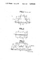
- FIG. 5 shows a curve of the insertion loss of an isolator as illustrated in FIG. 3;
- FIG. 6 shows a decoupling curve in the case of an isolator in accordance with the invention as illustrated in FIG. 3.
- FIG. 1 is a highly schematic illustration which recalls the structure of a nonreciprocal surface-wave device in accordance with the prior art. Said device is shown in the open state and is completed by its symmetrical counterpart with respect to the plane of the figure.
- the device comprises a parallelepipedal plate 1 of gyromagnetic conductive material against which is placed another parallelepipedal plate 2 of absorbing material. On these two plates is place a metallic sheet 3 of substantially trapezoidal shape, the long rectilinear side of which is in contact with the gyromagnetic material 1 and the short rectilinear side of which is in contact with (or outside) the absorbing material 2.
- the assembly is completed by a second conductive plate and a second absorbing plate which are symmetrical with respect to the metallic component 3 and is placed in a magnetic field H o produced by a magnet and pole-pieces (not shown in the drawings).
- the field H o is perpendicular to the plane of the component 3.
- Two input and output connectors (not shown) are connected to the ends 4 and 5 of the sheet 3.
- Said device further comprises three operating zones.
- the TEM-mode volume wave which is present at the input is converted to a surface wave (SEW).
- SEW surface wave
- the parasitic volume-mode waves are absorbed by the absorption load 2.
- a second coupling zone which is symmetrical with the first, reconverts the surface waves (SEW waves) to volume waves.
- the surface modes are transmitted in the forward input-output direction along the rectilinear edge of the core 3 while the parasitic modes emerging from the output are transmitted along the curvilinear edge of the core 3 and are absorbed by the absorption load 2.
- the transmission of these modes is indicated schematically by arrows.
- the object of the invention is to propose a novel concept whereby surface wave devices (SEW devices) no longer sustain volume modes as well as to propose simple means for providing high-performance, wide-band and compact isolators which achieve high isolation.
- SEW devices surface wave devices
- the mode of interest may be accompanied by undesirable modes.
- the useful frequency band and the characteristics of the volume permit this possibility, the most straightforward method consist in choosing these characteristics with a view to ensuring that the volume is capable of sustaining only a single mode.
- K non-diagonal element of the permeability tensor.
- volume modes may exist but their appearance can take place only if an excitation process exists.
- the volume modes are excitable:
- volume modes are therefore excitable, especially in the backward or reverse direction since it is practically impossible to construct an infinitely thin and perfectly straight core or a polycrystalline ferrite which is perfectly homogeneous and polished.
- FIG. 2 The view of a nonreciprocal device as illustrated in FIG. 2 is taken in cross-section along the line B--B' of FIG. 1 and also completes this latter by showing its symmetrical structure with respect to the central core 3.
- the ferrite components have an active width designated as S and extending between the rectilinear edge of the core and the dielectric discontinuity surface between ferrite 1 and absorber 2.
- the dashed line 6 represents the magnetic wall.
- Damping of a volume mode causes a drop in over-voltage of this latter and consequently in the proportion of energy extracted from the SEW mode.
- ⁇ gn guided-wave length of the volume mode of order n ##EQU3##
- the modes are such that their wave number k xn is equal to ##EQU4## S being the active width of the ferrite.
- the conceptual basis of the invention consists in preventing the phenomenon of resonance of higher-order modes and therefore the appearance of substantial couplings between the energy transported by these modes.
- a zone providing a strong coupling with the SEW mode which propagates in the reverse direction with respect to the low-loss direction at the edge of the central core opposite to the rectilinear edge which propagates the SEW wave in the forward direction is interposed in the resonator at the quasi-TE mode (that is, in the central zone of the core as described earlier) a zone providing a strong coupling with the SEW mode which propagates in the reverse direction with respect to the low-loss direction at the edge of the central core opposite to the rectilinear edge which propagates the SEW wave in the forward direction.
- the coupling zone is of sufficiently large size, that is to say at least one half-wave from the SEW mode, the resonance phenomenon is made impossible.
- the nonreciprocal device in accordance with the invention as illustrated in FIG. 3 has a general structure which closely resembles that of known devices of the type illustrated in FIG. 1.
- the device under consideration similarly comprises a plate 1 of gyromagnetic material such as a ferrite and a plate 2 forming an absorption load as well as a metallic core 9 which is preferably a thin sheet of copper.
- the originality of the device in accordance with the invention arises from the geometrical shape of the conductive core 9.
- This core again has a shape which recalls that of a curvilinear trapezium with a long rectilinear edge 9 extending between the input 4 and the output 5 in a direction parallel to the edge of the ferrite component 1.
- the shape of the core is completed by two curvilinear edges 11 and 12, the convexity of which is directed towards the long rectilinear edge 10.
- Said curvilinear edges join respectively the input 4 and the output 5 to the absorbing load 2.
- the short rectilinear edge of the core 3 of FIG. 1 is deeply recessed to form a curvilinear edge 13, the depth of the curve being such that a portion 14 of the edge 13 is located between the two ferrite plates 1.
- the coupling zone is formed precisely in the region just mentioned in which the portion 14 of the edge of the metallic core 19 is located between the ferrites 1. If the recess is not of sufficient depth and the edge 13 of the core 9 still remains between the two absorption loads 2, there is no coupling zone and no appreciable effect of suppression of volume modes.
- the curvilinear edge 13 can have a simple profile which may be circular, for example, or else a profile of the second degree such as an ellipse or a parabola. Said edge could also have a more complex shape and be either symmetrical or unsymmetrical with respect to a straight line perpendicular to the long edge 10.
- ZZ designates the length of the conductive core 9 at the level of the junction between ferrite 1 and absorber 2 on each side of the coupling zone of length Z, said length ZZ is preferentially: ##EQU7##
- the length ZZ must be sufficiently great since it is related to the transverse attentuation of the volume mode.
- the improvement achieved by the coupling zones finds its application in high-isolation devices.
- the isolation achieved by devices which operated in the SEW mode is a function of:
- One solution consists in constructing high-isolation devices in which a plurality of SEW isolators are placed in series but this has the effect of increasing the length of the device and its insertion losses at the same time as the isolation.
- high-isolation devices comprising a plurality (two, three, four, etc.) of coupling zones in order to increase the isolation without producing a proportional increase in insertion losses.
- FIG. 4 illustrates a high-isolation isolator having a core 9 comprising three coupling zones 14 between the SEW mode and the TE on modes. Irrespective of the number of coupling zones which are formed in the core 9, a greater number has the effect of increasing the insertion losses of the device but not in the same proportion since the propagation length does not vary in a proportional manner. However, said insertion losses remain low as shown by the curve of FIG. 5.
- the insertion losses of -1.8 dB at 6.5 GHz are uniformly comprised between -1.08 and -1.80 dB up to 17.5 GHz and do not exceed -2.05 dB at 18 GHz.
- FIG. 6 corresponds to decoupling of the same isolator within the same frequency band.
- the curve shown is not monotonic, it always remains within the range of -46.69 dB to -61.77 dB. This represents a considerable gain in the amount of isolation which, in the device of the prior art, is of the order of -20 dB to -35 dB in respect of insertion losses which are very close in value ( ⁇ 1.6 dB).
- the ferrite plates 1 preferably consist of one-piece slabs in each case while the absorbing loads 2 can consist of one or a number of parts which may or may not be in contact with the ferrites.
- the wave impedance of the absorbing material is preferably close in value to that of the SEW mode.
- the magnet and its pole-pieces are preferably integrated in the device in order to form a packaged assembly.
- the invention is applied to nonreciprocal devices providing high isolation in the microwave field.
Abstract
Description
Claims (7)
Applications Claiming Priority (2)
| Application Number | Priority Date | Filing Date | Title |
|---|---|---|---|
| FR8419923 | 1984-12-27 | ||
| FR8419923A FR2575605B1 (en) | 1984-12-27 | 1984-12-27 | NON-RECIPROCAL SURFACE WAVE MICROWAVE DEVICE AND HIGH INSULATION INSULATOR USING THE SAME |
Publications (1)
| Publication Number | Publication Date |
|---|---|
| US4698604A true US4698604A (en) | 1987-10-06 |
Family
ID=9311033
Family Applications (1)
| Application Number | Title | Priority Date | Filing Date |
|---|---|---|---|
| US06/813,002 Expired - Fee Related US4698604A (en) | 1984-12-27 | 1985-12-24 | Nonreciprocal microwave device for surface waves and an isolator having high isolation for the utilization of said device |
Country Status (6)
| Country | Link |
|---|---|
| US (1) | US4698604A (en) |
| EP (1) | EP0188966B1 (en) |
| JP (1) | JPS61203701A (en) |
| CA (1) | CA1240008A (en) |
| DE (1) | DE3575816D1 (en) |
| FR (1) | FR2575605B1 (en) |
Families Citing this family (1)
| Publication number | Priority date | Publication date | Assignee | Title |
|---|---|---|---|---|
| WO2023238310A1 (en) * | 2022-06-09 | 2023-12-14 | Tdk株式会社 | Non-reciprocal circuit element |
Citations (5)
| Publication number | Priority date | Publication date | Assignee | Title |
|---|---|---|---|---|
| FR2023812A1 (en) * | 1968-11-21 | 1970-08-21 | Western Microwave Labo | |
| US3886502A (en) * | 1974-08-06 | 1975-05-27 | Ryt Ind | Broad band field displacement isolator |
| US4050038A (en) * | 1974-09-04 | 1977-09-20 | Nippon Electric Company, Ltd. | Edge-guided mode non-reciprocal circuit element for microwave energy |
| US4152677A (en) * | 1976-03-10 | 1979-05-01 | Societe Lignes Telegraphiques Et Telephoniques | Wide band microwave isolators |
| FR2507391A1 (en) * | 1981-06-05 | 1982-12-10 | Thomson Csf | Microwave isolator with surface wave propagation - has two parallel plates of gyromagnetic material polarised by permanent magnet in contact with conducting plates |
-
1984
- 1984-12-27 FR FR8419923A patent/FR2575605B1/en not_active Expired
-
1985
- 1985-12-20 CA CA000498328A patent/CA1240008A/en not_active Expired
- 1985-12-24 DE DE8585402615T patent/DE3575816D1/en not_active Expired - Fee Related
- 1985-12-24 US US06/813,002 patent/US4698604A/en not_active Expired - Fee Related
- 1985-12-24 EP EP85402615A patent/EP0188966B1/en not_active Expired - Lifetime
- 1985-12-27 JP JP60299732A patent/JPS61203701A/en active Pending
Patent Citations (6)
| Publication number | Priority date | Publication date | Assignee | Title |
|---|---|---|---|---|
| FR2023812A1 (en) * | 1968-11-21 | 1970-08-21 | Western Microwave Labo | |
| US3617951A (en) * | 1968-11-21 | 1971-11-02 | Western Microwave Lab Inc | Broadband circulator or isolator of the strip line or microstrip type |
| US3886502A (en) * | 1974-08-06 | 1975-05-27 | Ryt Ind | Broad band field displacement isolator |
| US4050038A (en) * | 1974-09-04 | 1977-09-20 | Nippon Electric Company, Ltd. | Edge-guided mode non-reciprocal circuit element for microwave energy |
| US4152677A (en) * | 1976-03-10 | 1979-05-01 | Societe Lignes Telegraphiques Et Telephoniques | Wide band microwave isolators |
| FR2507391A1 (en) * | 1981-06-05 | 1982-12-10 | Thomson Csf | Microwave isolator with surface wave propagation - has two parallel plates of gyromagnetic material polarised by permanent magnet in contact with conducting plates |
Also Published As
| Publication number | Publication date |
|---|---|
| CA1240008A (en) | 1988-08-02 |
| FR2575605B1 (en) | 1987-02-06 |
| EP0188966A1 (en) | 1986-07-30 |
| DE3575816D1 (en) | 1990-03-08 |
| FR2575605A1 (en) | 1986-07-04 |
| JPS61203701A (en) | 1986-09-09 |
| EP0188966B1 (en) | 1990-01-31 |
Similar Documents
| Publication | Publication Date | Title |
|---|---|---|
| US3617951A (en) | Broadband circulator or isolator of the strip line or microstrip type | |
| EP0767507A1 (en) | Dielectric waveguide | |
| CN110692164B (en) | Non-reciprocal mode conversion substrate integrated waveguide | |
| US3845413A (en) | Wideband non reciprocal integrated circuits utilizing surface wave propagation | |
| US10615474B2 (en) | Apparatuses and methods for mode suppression in rectangular waveguide | |
| US3327250A (en) | Multi-mode broad-band selective coupler | |
| JP6489601B2 (en) | Non-reciprocal transmission line device and measuring method thereof | |
| Tsandoulas et al. | Longitudinal section mode analysis of dielectrically loaded rectangular waveguides with application to phase shifter design | |
| EP0120915B1 (en) | Millimeter-wave phase shifting device | |
| US4565984A (en) | Filter device utilizing magnetostatic waves | |
| Yoshinaga et al. | Design and fabrication of a nonradiative dielectric waveguide circulator | |
| US3534299A (en) | Miniature microwave isolator for strip lines | |
| US4698604A (en) | Nonreciprocal microwave device for surface waves and an isolator having high isolation for the utilization of said device | |
| Met | Absorptive filters for microwave harmonic power | |
| US4152677A (en) | Wide band microwave isolators | |
| US4186357A (en) | Non-reciprocal microwave phase shifters operating in a wide band on edge mode | |
| US3916352A (en) | Waveguide filters | |
| Nanda | A New Form of Ferrite Device for Millimeter-Wave Integrated Circuits (Short Papers) | |
| US4571562A (en) | Tunable selective devices based for magnetostatic volume waves | |
| US3919673A (en) | Nonreciprocal absorption filter | |
| US3445790A (en) | Ferrite waveguide device having magnetic return path within the waveguide | |
| US3617950A (en) | Junction circulator having a conductive septum in junction region | |
| Tsutsumi et al. | On the YIG film waveguides | |
| US3833868A (en) | Dual balanced reciprocal waveguide phase shifter | |
| Piltyay et al. | Electromagnetic Performance and Application of Microwave Ferromagnetic Devices |
Legal Events
| Date | Code | Title | Description |
|---|---|---|---|
| AS | Assignment |
Owner name: THOMSON-CSF, 173-, B1. HAUSSMANN 75008 PARIS FRANC Free format text: ASSIGNMENT OF ASSIGNORS INTEREST.;ASSIGNORS:FORTERRE, GERARD;GUERIN, BERNARD;REEL/FRAME:004743/0791 Effective date: 19851127 Owner name: THOMSON-CSF, FRANCE Free format text: ASSIGNMENT OF ASSIGNORS INTEREST;ASSIGNORS:FORTERRE, GERARD;GUERIN, BERNARD;REEL/FRAME:004743/0791 Effective date: 19851127 |
|
| FEPP | Fee payment procedure |
Free format text: MAINTENANCE FEE HAS ALREADY BEEN PAID. REFUND IS SCHEDULED (ORIGINAL EVENT CODE: F160); ENTITY STATUS OF PATENT OWNER: LARGE ENTITY |
|
| FEPP | Fee payment procedure |
Free format text: PAYOR NUMBER ASSIGNED (ORIGINAL EVENT CODE: ASPN); ENTITY STATUS OF PATENT OWNER: LARGE ENTITY |
|
| FPAY | Fee payment |
Year of fee payment: 4 |
|
| REMI | Maintenance fee reminder mailed | ||
| LAPS | Lapse for failure to pay maintenance fees | ||
| FP | Lapsed due to failure to pay maintenance fee |
Effective date: 19951011 |
|
| STCH | Information on status: patent discontinuation |
Free format text: PATENT EXPIRED DUE TO NONPAYMENT OF MAINTENANCE FEES UNDER 37 CFR 1.362 |