US4698114A - Apparatus for applying strip reinforcing to sheet material - Google Patents
Apparatus for applying strip reinforcing to sheet material Download PDFInfo
- Publication number
- US4698114A US4698114A US06/829,800 US82980086A US4698114A US 4698114 A US4698114 A US 4698114A US 82980086 A US82980086 A US 82980086A US 4698114 A US4698114 A US 4698114A
- Authority
- US
- United States
- Prior art keywords
- strip
- sheet
- blade
- transport direction
- path
- Prior art date
- Legal status (The legal status is an assumption and is not a legal conclusion. Google has not performed a legal analysis and makes no representation as to the accuracy of the status listed.)
- Expired - Fee Related
Links
Images


Classifications
-
- B—PERFORMING OPERATIONS; TRANSPORTING
- B31—MAKING ARTICLES OF PAPER, CARDBOARD OR MATERIAL WORKED IN A MANNER ANALOGOUS TO PAPER; WORKING PAPER, CARDBOARD OR MATERIAL WORKED IN A MANNER ANALOGOUS TO PAPER
- B31F—MECHANICAL WORKING OR DEFORMATION OF PAPER, CARDBOARD OR MATERIAL WORKED IN A MANNER ANALOGOUS TO PAPER
- B31F5/00—Attaching together sheets, strips or webs; Reinforcing edges
- B31F5/06—Attaching together sheets, strips or webs; Reinforcing edges by adhesive tape
- B31F5/08—Attaching together sheets, strips or webs; Reinforcing edges by adhesive tape for reinforcing edges ; Applying a strip or tape to an edge, e.g. for decorating, for protecting
-
- B—PERFORMING OPERATIONS; TRANSPORTING
- B29—WORKING OF PLASTICS; WORKING OF SUBSTANCES IN A PLASTIC STATE IN GENERAL
- B29C—SHAPING OR JOINING OF PLASTICS; SHAPING OF MATERIAL IN A PLASTIC STATE, NOT OTHERWISE PROVIDED FOR; AFTER-TREATMENT OF THE SHAPED PRODUCTS, e.g. REPAIRING
- B29C66/00—General aspects of processes or apparatus for joining preformed parts
- B29C66/01—General aspects dealing with the joint area or with the area to be joined
- B29C66/05—Particular design of joint configurations
- B29C66/10—Particular design of joint configurations particular design of the joint cross-sections
- B29C66/11—Joint cross-sections comprising a single joint-segment, i.e. one of the parts to be joined comprising a single joint-segment in the joint cross-section
- B29C66/112—Single lapped joints
- B29C66/1122—Single lap to lap joints, i.e. overlap joints
-
- B—PERFORMING OPERATIONS; TRANSPORTING
- B29—WORKING OF PLASTICS; WORKING OF SUBSTANCES IN A PLASTIC STATE IN GENERAL
- B29C—SHAPING OR JOINING OF PLASTICS; SHAPING OF MATERIAL IN A PLASTIC STATE, NOT OTHERWISE PROVIDED FOR; AFTER-TREATMENT OF THE SHAPED PRODUCTS, e.g. REPAIRING
- B29C66/00—General aspects of processes or apparatus for joining preformed parts
- B29C66/40—General aspects of joining substantially flat articles, e.g. plates, sheets or web-like materials; Making flat seams in tubular or hollow articles; Joining single elements to substantially flat surfaces
- B29C66/47—Joining single elements to sheets, plates or other substantially flat surfaces
- B29C66/472—Joining single elements to sheets, plates or other substantially flat surfaces said single elements being substantially flat
- B29C66/4722—Fixing strips to surfaces other than edge faces
-
- B—PERFORMING OPERATIONS; TRANSPORTING
- B29—WORKING OF PLASTICS; WORKING OF SUBSTANCES IN A PLASTIC STATE IN GENERAL
- B29C—SHAPING OR JOINING OF PLASTICS; SHAPING OF MATERIAL IN A PLASTIC STATE, NOT OTHERWISE PROVIDED FOR; AFTER-TREATMENT OF THE SHAPED PRODUCTS, e.g. REPAIRING
- B29C66/00—General aspects of processes or apparatus for joining preformed parts
- B29C66/70—General aspects of processes or apparatus for joining preformed parts characterised by the composition, physical properties or the structure of the material of the parts to be joined; Joining with non-plastics material
- B29C66/71—General aspects of processes or apparatus for joining preformed parts characterised by the composition, physical properties or the structure of the material of the parts to be joined; Joining with non-plastics material characterised by the composition of the plastics material of the parts to be joined
-
- Y—GENERAL TAGGING OF NEW TECHNOLOGICAL DEVELOPMENTS; GENERAL TAGGING OF CROSS-SECTIONAL TECHNOLOGIES SPANNING OVER SEVERAL SECTIONS OF THE IPC; TECHNICAL SUBJECTS COVERED BY FORMER USPC CROSS-REFERENCE ART COLLECTIONS [XRACs] AND DIGESTS
- Y10—TECHNICAL SUBJECTS COVERED BY FORMER USPC
- Y10T—TECHNICAL SUBJECTS COVERED BY FORMER US CLASSIFICATION
- Y10T156/00—Adhesive bonding and miscellaneous chemical manufacture
- Y10T156/12—Surface bonding means and/or assembly means with cutting, punching, piercing, severing or tearing
- Y10T156/1317—Means feeding plural workpieces to be joined
- Y10T156/1322—Severing before bonding or assembling of parts
- Y10T156/1326—Severing means or member secured thereto also bonds
-
- Y—GENERAL TAGGING OF NEW TECHNOLOGICAL DEVELOPMENTS; GENERAL TAGGING OF CROSS-SECTIONAL TECHNOLOGIES SPANNING OVER SEVERAL SECTIONS OF THE IPC; TECHNICAL SUBJECTS COVERED BY FORMER USPC CROSS-REFERENCE ART COLLECTIONS [XRACs] AND DIGESTS
- Y10—TECHNICAL SUBJECTS COVERED BY FORMER USPC
- Y10T—TECHNICAL SUBJECTS COVERED BY FORMER US CLASSIFICATION
- Y10T156/00—Adhesive bonding and miscellaneous chemical manufacture
- Y10T156/12—Surface bonding means and/or assembly means with cutting, punching, piercing, severing or tearing
- Y10T156/1317—Means feeding plural workpieces to be joined
- Y10T156/1343—Cutting indefinite length web after assembly with discrete article
Definitions
- the present invention relates, in general, to apparatus for applying reinforcing of one material to a substrate sheet of another material, and, more particularly, to an apparatus for applying strip reinforcing along a margin of a sheet substrate and means for severing the strip at the trailing edge of the sheet.
- an object of the present invention to provide an improved apparatus for applying strip reinforcing to sheet material in which the reinforcing strip and the sheet substrate can be continuously advanced while the strip is being severed.
- the substrate sheets are displaced from a feeder station into a tacking, cutting and sealing station which contains a supply of reinforcing film to be applied to the sheet, forming the reinforcing strip.
- a tacking, cutting and sealing station which contains a supply of reinforcing film to be applied to the sheet, forming the reinforcing strip.
- the leading edge thereof triggers a microswitch or sensor which activates a single revolution, wrapped spring clutch which rotates a cam shaft.
- the cam shaft is operatively connected to several elements of the tacking, cutting and sealing station, one of which is the cutting device, which is retracted out of the path of the strip by the rotation of the cam shaft, which also acts to lower an upper tacking roller positioned above th epath of the strip, also lowering a strip guide for directing the strip into contact with the sheet while spring loading a lower tacking roller juxtaposed with the upper roller against a trip which holds the lower roller just clear of the upper roller and allows the sheet and strip to pass therebetween.
- the sheet leading edge of the sheet is detected by an electric eye which triggers the discharge of a condenser into a solenoid operatively connected to the trip, releasing the spring loaded lower tacking roller against the upper tacking roller with the sheet and strip pressed therebetween, tacking the strip to the sheet at an adjustable distance from the leading edge thereof, the two tacking rollers maintaining contact until the sheet and strip are fed between sealing rollers downstream of the tacking rollers.
- the upper tacking roller is then lifted, the guide strip is also lifted to provide spacing between the strip and the sheet upstream or past the tacking point therebetween, the cutting device is swung back into the path of the strip, with a lower blade of the device lying between the strip and sheet, and the spring pressure on the lower tacking roller is released, allowing the trip lever to reengage and completing the revolution of the cam shaft.
- the trailing edge of the sheet is detected by another electric eye associated with the cutting device which triggers the discharge of another condenser into another solenoid operatively connected with an upper blade of the cutting device above the strip and juxtaposed with the stationary lower blade, driving the upper blade toward the lower blade or sever the strip at or at an adjustable distance inside from the trailing edge of the sheet.
- the reinforced and trimmed sheet passes through the set of sealing rollers where the strip is bonded to the substrate, it is conveyed into a hole punching station where it is stopped, at which point a high speed punching unit driven by another single revolution, wrapped spring clutch triggered by another electric eye activating the discharge of another condenser into another solenoid operatively connected to the punching unit for high speed operation thereof punches the required holes.
- the punched reinforced sheet is then passed to a hopper.
- the moving strip is never severed by a stationary cutting device for fear of tearing the strip already tacked and partially bonded to the sheet.
- this is what is done and achieved by operating the cutting device with a solenoid powered by the discharge of a condenser, which results in an almost instantaneous reaction of the cutting blades, severing the strip, starting from one longitudinal edge to the other, much more rapidly than heretofore achieved.
- the blades are arranged at a slight angle in projection at the plane of the strip to a perpendicular to the transport direction in the plane of the strip, whereby because of the angle and the motion of the strip, the cut is formed from edge to edge substantially perpendicular to the transport direction and the longitudinal edges of the strip.
- FIG. 1 is a front elevational view in a diagrammatic form of the apparatus according to the invention.
- FIG. 2 is a top plan view thereof
- FIGS. 3 to 6 are rear elevational views in diagrammatic form showing in operational sequence the details of the tacking, cutting and sealing station of FIGS. 1 and 2;
- FIG. 7 is a view similar to FIGS. 3-6 showing further details of the station
- FIG. 8 is a detail view of the cutting device according to the invention in an operational position
- FIG. 9 is a view similar to FIG. 8 showing the cutting device in a retracted, non-operational position
- FIG. 10 is a top plan view of FIG. 8;
- FIG. 11 is a view similar to FIG. 8 showing another embodiment of the invention.
- FIG. 12 is atop plan view thereof.
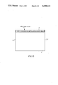
- FIG. 13 is a plan view of a finished reinforced sheet.
- FIGS. 1 and 2 are overall views of the apparatus for applying strip reinforcing to sheet material, at the upstream end of which there is provided a feeder station 1 having the standard rollers and belts for conveying the sheet material to be reinforced to a tacking, cutting and sealing station 2 carrying a spool 3 of reinforcing film which is used as the reinforcing medium in the form of a strip 4 which is applied to the margin of substrate sheets 5 in the station 2 under the control of an instrument panel 6 also provided in the station.
- a sheet is reinforced at the station 2 it is conveyed to a hole punching station 7 provided with a punching die 8, a sheet stop 9 and a jogger rail 10.
- a hopper 11 is provided for collecting the finished sheets.
- FIGS. 3-7 show in detail those elements of station 2 directly responsible for tacking, cutting and sealing of the reinforcing film to a substrate, there is provided a microswitch 12 engageable by the leading edge 5.1 of a sheet 5 and operatively connected to a single revolution, wrapped spring clutch 14 which rotates a cam shaft 15, an upper tacking roller 16 operatively connected to cam shaft 15 by a pushrod 17 for raising and lowering the roller, and a movable strip guide 13 operatively connected to the upper tacking roller 16 by an arm 18 for directing the strip 4 toward or away from the sheet 5.
- a microswitch 12 engageable by the leading edge 5.1 of a sheet 5 and operatively connected to a single revolution, wrapped spring clutch 14 which rotates a cam shaft 15, an upper tacking roller 16 operatively connected to cam shaft 15 by a pushrod 17 for raising and lowering the roller, and a movable strip guide 13 operatively connected to the upper tacking roller 16 by an arm 18 for directing the strip 4 toward or away from the sheet
- a lower tacking roller 19 is juxtaposed with the upper roller 16 and is biased upwardly by a spring 20 tensioned by the rotation of cam shaft 15 through the pushrod 21, the lower roller 19 being held in a cocked position against the spring tension by a trip lever 22 releasable by a solenoid 23, which is activated by an electric eye 24 upon detection of the leading edge 5.1 of a sheet 5 entering the space between the upper and lower rollers 16 and 19, the point of detection being adjustable by the displacement of the electric eye 24 in the transport direction along a threaded rod 25.
- the cam shaft 15 is also operatively connected by a pushrod 26 to a cutting device 27 to swing the device between an operative position shown in FIG. 8 and a retracted non operative position shown in FIG. 9.
- Another electric eye 28 associated with the cutting device 27 is provided along the transport and is adjustable in the transport direction by a threaded rod 29.
- the electric eye 28 is connected to a solenoid 30, which is operatively connected to the swingable upper blade 31 positioned above the strip 4 and coacting with the stationary lower blade 32 positioned below the strip 4 and on which the upper blade 31 is pivotally mounted to cut the strip 4 from one edge to another in a scissor-like manner.
- the solenoid 30 is connected to a D.C. power supply 33 which feeds through a condenser 34, which provides jolt of power to the solenoid when the electric switch 35 is closed upon detection of the trailing edge 5.2 of a sheet 5 by the electric eye 28 in alignment with the cutting device 27.
- the cutting device 27 is swingably mounted on pivot 27.1, which allows the device to be retracted into the non-operative position shown in FIG. 9 by the pushrod 26 connected by a swivel 26.1 to a connecting arm 26.2 pivotally connected to the cutting device 27.
- a compression spring 36 mounted between the solenoid 30 and the movable blade acts to bias the cutting blades in an open position.
- the cutting device 27 is further adjustable in the horizontal plane by the clamp 27.2 by which the device is mounted on an upright stanchoin 37, which allows the angle ⁇ of the projection of the blades on the strip 4 relative to the perpendicular to the transport direction to be changed, whereby the cut across the strip 4 can be formed substantially perpendicular to the transport direction by adjustment of this angle ⁇ relative to the velocity of the strip. Without this adjustment, the cut would be formed at an angle because of the motion of the strip.
- FIGS. 11 and 12 Another embodiment of the cutting device 27' is shown in FIGS. 11 and 12, in which the upper movable blade 31' is displaced vertically instead of pivotally by the solenoid 30' which acts against the restoring tension spring 36' to drive the blade 31' downwardly in a guide 38 toward the stationary blade 32'.
- the cutting edge 31.1' of the upper blade 31' is formed as a concave arc, whereby the cut is formed inwardly toward the center from each edge of the strip 4.
- both blades 31' and 32' are bowed in the vertical plane in the transport direction, so that the tangent to the bow at the ends when projected onto the strip 4 forms the angle ⁇ with the perpendicular to the transport direction in the plane of the strip, whereby the combination of the velocity of the strip and the cutting angle ⁇ produce a substantially straight cut across the strip.
- a finished sheet 5 having a reinforced marginal strip 4 in which the holes have been punched is shown in FIG. 13.
- a set of metallic sealing rollers 39 through which the sheet 5 with the applied strip 4 is passed, the rollers 39 being contacted by electrical brushes 40 which supply heating current to the rollers 39 for sealing the strip 4 to the substrate sheet 5 as it passes through, thereby bonding the strip to the sheet.
- the substrate sheets 5 are displaced from the feeder station 1 into the tacking, cutting and sealing station 2, which contains a supply of Mylar film on a spool 3 to be applied to the sheet 5, forming the reinforcing strip 4.
- the leading edge 5.1 thereof triggers the microswitch 12 which activates the single revolution, wrapped spring clutch 14 which rotates the cam shaft 15.
- the cam shaft 15 is operatively connected by the pushrods to several elements of the station 2, one of which is the cutting device 27 operated by the pushrod 26 and connecting arm 26.2, which acts to retract the cutting device out of the path of the advancing strip 4 by the rotation of the cam shaft 15, which also acts through the pushrod 17 to lower the upper tracking roller 16 positioned above the path of the strip 4, the upper tacking roller 16 being operatively connected to the strip guide 13 by the arm 18, so that when the roller 16 is lowered the strip guide 13 is also lowered and directs the strip 4 into contact with the sheet 5 while spring loading the lower tacking roller 19 with a compression spring 20 acted on by the pushrod 21, the spring loaded roller 19 being held in a cocked position just clear of the upper roller 16 by the strip level 22.
- the electric eye 24 which triggers the discharge of a condenser, similar to the one illustrated in FIG. 8 into the solenoid 23 operatively connected to the trip lever 22, releasing the spring loaded lower tacking roller 19 against the upper tacking roller 16 with the sheet and strip pressed therebetween, thereby tacking the strip 4 to the sheet 5 at a distance from the leading edge 5.1 which is adjustable by shifting the electric eye 24 in the transport direction using the threaded rod 25.
- the upper and lower tacking rollers maintain contact with the sheet and strip therebetween until the sheet and strip are fed between the sealing rollers 39 where the strip 4 is bonded to the sheet 5 by heat.
- the upper tacking roller 16 is then lifted along with the strip guide 13 to provide spacing between the strip 4 and sheet 5 upstream or past the tacking point therebetween allowing the cutting device 27 to be swung into the path of the strip with the lower blade 32 thereof lying between the strip 4 and the sheet 5, while at the same time the spring pressure on the lower tacking roller 19 is relieved, allowing the trip lever 22 to reengage in the cocked position of the lower tacking roller 19 and completing one revolution of the cam shaft 15.
- the trailing edge 5.2 of the sheet 5 is detected by another electric eye 28 associated with the cutting device 27 and which triggers the discharge of another condenser, similar to the one illustrated in FIG.
- the reinforced and trimmed sheet 5 passes through the set of sealing rollers 39 where the strip 4 is bonded to the substrate 5, it is conveyed into the hole punching station 7 where it is stopped by the sheet stop 9 jogged into register by the jogger rail 10, at which point a high speed punching unit 8 driven by another single revolution, wrapped spring clutch similar to the one illustrated in FIG. 7, is triggered by another electric eye activating the discharge of another condenser into another solenoid arranged in a circuit similar to that illustrated in FIG. 8, the solenoid being operatively connected to the punching unit 8 for high speed punching of the holes in the reinforcing stacked sheets. After punching, the sheets is passed to a hopper 11 for collection.
Landscapes
- Engineering & Computer Science (AREA)
- Mechanical Engineering (AREA)
- Folding Of Thin Sheet-Like Materials, Special Discharging Devices, And Others (AREA)
Abstract
Description
Claims (14)
Priority Applications (1)
| Application Number | Priority Date | Filing Date | Title |
|---|---|---|---|
| US06/829,800 US4698114A (en) | 1986-02-14 | 1986-02-14 | Apparatus for applying strip reinforcing to sheet material |
Applications Claiming Priority (1)
| Application Number | Priority Date | Filing Date | Title |
|---|---|---|---|
| US06/829,800 US4698114A (en) | 1986-02-14 | 1986-02-14 | Apparatus for applying strip reinforcing to sheet material |
Publications (1)
| Publication Number | Publication Date |
|---|---|
| US4698114A true US4698114A (en) | 1987-10-06 |
Family
ID=25255594
Family Applications (1)
| Application Number | Title | Priority Date | Filing Date |
|---|---|---|---|
| US06/829,800 Expired - Fee Related US4698114A (en) | 1986-02-14 | 1986-02-14 | Apparatus for applying strip reinforcing to sheet material |
Country Status (1)
| Country | Link |
|---|---|
| US (1) | US4698114A (en) |
Cited By (6)
| Publication number | Priority date | Publication date | Assignee | Title |
|---|---|---|---|---|
| FR2621854A1 (en) * | 1987-10-20 | 1989-04-21 | Symalit Lizenz Ag | Method of continuously manufacturing a plastic tube having a longitudinal closure and tubes manufactured by this method |
| US5188694A (en) * | 1989-10-18 | 1993-02-23 | Sun Seiki Co., Ltd. | Sheet perforating apparatus |
| US5277722A (en) * | 1991-03-18 | 1994-01-11 | E-Z Machine Corp. | Manually fed machine for the formation of tabs on sheet stock |
| US5304275A (en) * | 1993-03-03 | 1994-04-19 | E-Z Machine Corp. | Applying a reinforcement film to sheets |
| US5421947A (en) * | 1992-09-24 | 1995-06-06 | Green; Diane | Laminating machine |
| US20150266255A1 (en) * | 2014-03-19 | 2015-09-24 | E.L. Hatton Sales Co. | Banner making machine |
Citations (6)
| Publication number | Priority date | Publication date | Assignee | Title |
|---|---|---|---|---|
| US2248744A (en) * | 1938-03-30 | 1941-07-08 | S & S Corrugated Paper Mach | Taping machine |
| US2864285A (en) * | 1954-05-24 | 1958-12-16 | S & S Corrugated Paper Mach | Taping machine |
| US3479242A (en) * | 1966-07-18 | 1969-11-18 | Scott Equipment Co | Reinforcing machine |
| US3925144A (en) * | 1973-10-18 | 1975-12-09 | E Z Machine Corp | Apparatus for applying reinforcement zones to sheet material |
| US3926713A (en) * | 1973-08-30 | 1975-12-16 | E Z Machine Corp | Apparatus for producing and assembling tabbed cards |
| US4448631A (en) * | 1983-02-12 | 1984-05-15 | Banctec, Inc. | Encodable strip attachment apparatus |
-
1986
- 1986-02-14 US US06/829,800 patent/US4698114A/en not_active Expired - Fee Related
Patent Citations (6)
| Publication number | Priority date | Publication date | Assignee | Title |
|---|---|---|---|---|
| US2248744A (en) * | 1938-03-30 | 1941-07-08 | S & S Corrugated Paper Mach | Taping machine |
| US2864285A (en) * | 1954-05-24 | 1958-12-16 | S & S Corrugated Paper Mach | Taping machine |
| US3479242A (en) * | 1966-07-18 | 1969-11-18 | Scott Equipment Co | Reinforcing machine |
| US3926713A (en) * | 1973-08-30 | 1975-12-16 | E Z Machine Corp | Apparatus for producing and assembling tabbed cards |
| US3925144A (en) * | 1973-10-18 | 1975-12-09 | E Z Machine Corp | Apparatus for applying reinforcement zones to sheet material |
| US4448631A (en) * | 1983-02-12 | 1984-05-15 | Banctec, Inc. | Encodable strip attachment apparatus |
Cited By (9)
| Publication number | Priority date | Publication date | Assignee | Title |
|---|---|---|---|---|
| FR2621854A1 (en) * | 1987-10-20 | 1989-04-21 | Symalit Lizenz Ag | Method of continuously manufacturing a plastic tube having a longitudinal closure and tubes manufactured by this method |
| US5188694A (en) * | 1989-10-18 | 1993-02-23 | Sun Seiki Co., Ltd. | Sheet perforating apparatus |
| US5277722A (en) * | 1991-03-18 | 1994-01-11 | E-Z Machine Corp. | Manually fed machine for the formation of tabs on sheet stock |
| US5421947A (en) * | 1992-09-24 | 1995-06-06 | Green; Diane | Laminating machine |
| US5304275A (en) * | 1993-03-03 | 1994-04-19 | E-Z Machine Corp. | Applying a reinforcement film to sheets |
| US20150266255A1 (en) * | 2014-03-19 | 2015-09-24 | E.L. Hatton Sales Co. | Banner making machine |
| WO2015142557A1 (en) * | 2014-03-19 | 2015-09-24 | E.L. Hatton Sales Co. | Banner making machine |
| US9987816B2 (en) * | 2014-03-19 | 2018-06-05 | E.L. Hatton Sales Co. | Banner making machine |
| US20180339482A1 (en) * | 2014-03-19 | 2018-11-29 | E.L. Hatton Sales Co. | Banner making machine |
Similar Documents
| Publication | Publication Date | Title |
|---|---|---|
| US3890886A (en) | Apparatus for interleaving sheets of paper between individual slices of cheese for packages of sliced cheese | |
| US4750853A (en) | Device for conveying a bundle of sheets | |
| EP0159717B1 (en) | Receiving and stacking apparatus for strips of sheet material | |
| EP0472245A1 (en) | Apparatus for continuously unwinding a plurality of rolled-up tapes | |
| JP3326119B2 (en) | Bookbinding device | |
| JPS6186351A (en) | Raw fabric reel changeover method for packaging machine and device thereof | |
| US4698114A (en) | Apparatus for applying strip reinforcing to sheet material | |
| US5050812A (en) | Dual-envelope making machine and method of using | |
| US3306801A (en) | Web severing means for web splicing machines | |
| GB1381779A (en) | Transport guide for pliable sheet material | |
| US4732067A (en) | Veneer clipper | |
| US4798351A (en) | Apparatus for coiling a foil web, especially a synthetic resin foil web | |
| CA1180260A (en) | Web splicing apparatus | |
| US4175476A (en) | Method and apparatus for forming reinforced top file folders | |
| US5069659A (en) | Apparatus for the production of shopping bags having reinforced handle holes | |
| JP2609275B2 (en) | Hot air sealer | |
| US5049117A (en) | Dual-envelope making machine and method of using | |
| JPH06190777A (en) | Paper roll cutting device | |
| JPH0853250A (en) | Paper cutter | |
| US5277722A (en) | Manually fed machine for the formation of tabs on sheet stock | |
| JP2008230855A (en) | Device for collecting printed product on collecting cylinder | |
| US5304275A (en) | Applying a reinforcement film to sheets | |
| US2324950A (en) | Edge trimming means for use in rotary printing presses | |
| US2861633A (en) | Automatic tape dispenser | |
| JP2001515434A (en) | Labeling machine without liner |
Legal Events
| Date | Code | Title | Description |
|---|---|---|---|
| AS | Assignment |
Owner name: E-Z MACHINE CORP., 112 NEWTOWN ROAD, PLAINVIEW, N. Free format text: ASSIGNMENT OF ASSIGNORS INTEREST.;ASSIGNOR:LOWE, WILLIAM F.;REEL/FRAME:004518/0445 Effective date: 19860203 Owner name: E-Z MACHINE CORP.,NEW YORK Free format text: ASSIGNMENT OF ASSIGNORS INTEREST;ASSIGNOR:LOWE, WILLIAM F.;REEL/FRAME:004518/0445 Effective date: 19860203 |
|
| FEPP | Fee payment procedure |
Free format text: PAYOR NUMBER ASSIGNED (ORIGINAL EVENT CODE: ASPN); ENTITY STATUS OF PATENT OWNER: SMALL ENTITY |
|
| FPAY | Fee payment |
Year of fee payment: 4 |
|
| FPAY | Fee payment |
Year of fee payment: 8 |
|
| REMI | Maintenance fee reminder mailed | ||
| LAPS | Lapse for failure to pay maintenance fees | ||
| FP | Lapsed due to failure to pay maintenance fee |
Effective date: 19991006 |
|
| STCH | Information on status: patent discontinuation |
Free format text: PATENT EXPIRED DUE TO NONPAYMENT OF MAINTENANCE FEES UNDER 37 CFR 1.362 |