US4675540A - Toggle electrical switch - Google Patents
Toggle electrical switch Download PDFInfo
- Publication number
- US4675540A US4675540A US06/702,052 US70205285A US4675540A US 4675540 A US4675540 A US 4675540A US 70205285 A US70205285 A US 70205285A US 4675540 A US4675540 A US 4675540A
- Authority
- US
- United States
- Prior art keywords
- conductive
- slide
- conductive track
- substrate
- track
- Prior art date
- Legal status (The legal status is an assumption and is not a legal conclusion. Google has not performed a legal analysis and makes no representation as to the accuracy of the status listed.)
- Expired - Fee Related
Links
Images


Classifications
-
- H—ELECTRICITY
- H01—ELECTRIC ELEMENTS
- H01H—ELECTRIC SWITCHES; RELAYS; SELECTORS; EMERGENCY PROTECTIVE DEVICES
- H01H3/00—Mechanisms for operating contacts
- H01H3/02—Operating parts, i.e. for operating driving mechanism by a mechanical force external to the switch
- H01H3/0213—Combined operation of electric switch and variable impedance, e.g. resistor, capacitor
-
- H—ELECTRICITY
- H01—ELECTRIC ELEMENTS
- H01H—ELECTRIC SWITCHES; RELAYS; SELECTORS; EMERGENCY PROTECTIVE DEVICES
- H01H23/00—Tumbler or rocker switches, i.e. switches characterised by being operated by rocking an operating member in the form of a rocker button
- H01H23/02—Details
- H01H23/12—Movable parts; Contacts mounted thereon
- H01H23/16—Driving mechanisms
- H01H23/164—Driving mechanisms with rectilinearly movable member carrying the contacts
Definitions
- This invention relates generally to power control switches and specifically to power switches with variable control output.
- toggle switch mounted on a wall.
- the toggle switch includes an off position and on position and is located electrically between the power source and the power load, most commonly a light.
- the toggle switch serves to physically make or break contact to establish or break the circuit connection between the load and the power source.
- An alternative circuit configuration includes two toggle switches connected in series between the power source and the load.
- the type of toggle switch used in this configuration is normally referred to a "three wire" switch wherein there is a two wire parallel connection between the two toggle switches, with one toggle switch connected to a single line to the power source and a second toggle switch connected to the load. In this "three wire” configuration, either toggle switch may be used to make or break the power source connection to the load.
- toggle switch that includes a switching function and a variable control function to regulate power to a load.
- an electrical switch in accordance with the present invention includes a toggle lever pivotally mounted to a switch housing and further connected to a slide in a manner to provide longitudinal motion to the slide between first and second end limit positions when the toggle lever is pivoted.
- the slide includes a first conductor which when the slide is located in the first end limit position maintains contact with a first conductive track and when the slide is located in the second end limit position provides an electrical conduction path between the first conductive track and a second conductive track.
- the conductor When the slide is located in a position between the first and second end limits, the conductor provides a second conduction path between the first conductive track and a third conductive track.
- the first conductor is further connected to a second conductor in the slide which is in sliding contact with a circuit contained upon a substrate and connected between the first and third conductive tracks.
- the substrate is mounted upon the switch housing parallel to the longitudinal motion of the slide and perpendicular to the pivotal rotation of the toggle lever to provide power from the first conductive track to the a load connected to the third conductive track at a level that varies with the longitudinal position of the second conductor upon the circuit.
- the electrical switch includes the first conductive track connected to a power source with the second conductive track connected to the load wherein, in the first limit position the power source is isolated from the load and in the second limit position, the power source is directly connected to the load.
- the second conductor contained within the slide is in slidable contact with a variable resistor contained upon the substrate circuit surface and whose resistance varies in accordance with the longitudinal position of the second conductor upon the resistor.
- the variable resistor includes two strips upon the substrate with one strip being a conductive strip and a second strip being a resistive strip. The second conductor is in slideable contact with both strips and shorts the conductive strip to different portions of the resistive strip to provide the variable resistance function.
- the circuit contains a regulation device connected between the first and third nodes for regulating power to a load connected to the third conductive track.
- this regulation device is a triac that is formed upon the substrate surface.
- the circuit includes a capacitor chargeable through the resistor and connected to a diac and then to the gate of the triac resulting in the triac regulating the power to the load in accordance with the charge upon the capacitor.
- an inductor and a second capacitor are connected to the circuit to reduce electromagnetic interference caused by the switching of power.
- an electrical switch in an alternative embodiment, includes a toggle lever pivotally mounted to a switch housing and further connected to a slide to provide longitudinal motion to the slide between the first and second end limit positions resulting from the pivoting of the toggle lever.
- the slide includes a first conductor which provides an electrical conduction path between a first conductive track and a conductive plate; when the slide is located in the second end limit position, the conductor provides an electrical conduction path between the first conductive track and a second conductive track; and when the slide is located between the first and second end limit positions, the conductor provides a conduction path between the first conductive track and a third conductive track.
- the first conductor is further connected to a second conductor in the slide with the second conductor being in sliding contact with a circuit contained upon a substrate and further connected between the first and third conductive tracks.
- the substrate is mounted in the switch housing parallel to the longitudinal motion of the slide and perpendicular to the pivotal rotation of the toggle lever.
- the switch When the switch is in the first end limit position the switch connects the first conductive track to the conductive plate in a manner similar to a three wire toggle switch.
- the switch When the switch is in the second end limit position the switch provides a connection between the first conductive track and second conductive track to provide an unregulated power connection between the first conductive track and second conductive track.
- the third conductive track is as previously discussed, connected to the first conductive track through the circuit to variably regulate power to the load.
- variable control switch When connected in the three wire switch configuration, the variable control switch, in a variable control position, will either provide power under the variable control state or provide an on/off switch function depending upon the location of the variable control switch in the circuit configuration and the specific switch setting of the second switch in the circuit.
- FIG. 1 is a perspective view of the electrical switch.
- FIG. 2A is a rear elevation view of the electrical switch with the rear cover removed.
- FIG. 2B is a rear elevation view of a second embodiment of the electrical switch for a three wire switch configuration.
- FIG. 2C is a rear elevation view of the electrical switch with a cutaway section illustrating the wiper underneath the gate.
- FIG. 3 is an exploded view of the switch substrate and contact components.
- FIG. 4A is a schematic diagram of the electrical switch.
- FIG. 4B is a schematic diagram of the three wire configured electrical switch.
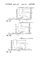
- FIG. 5A is a front view diagram of the hammer conductor contained within the slide in the first limit position.
- FIG. 5B is a side view of the hammer contained within the slide in a position between the first and second limit positions.
- FIG. 5C is a side view of the slide hammer in the second limit position.
- FIG. 1 illustrates the invention in an assembled form. From the front the outward appearance of the invention is very similar to the standard toggle switch that is customarily used in the home. The invention, however, provides the additional feature of variable control. Additionally, FIG. 1 illustrates that the invention is of a low profile, i.e. of a shallower depth, than the traditional toggle switch for light control. This low profile and variable control function are a result of the unique structure of this invention.
- the invention consists of a wall plate 10 that includes the switch housing 16 mounted thereon. In the preferred embodiment, the wall plate 10 is metal and the switch housing 16 is plastic.
- the switch housing includes an extended section 16A through the plate 10 for encompassing the toggle lever 18.
- the toggle lever 18 is mounted pivotally within the extension 16A. Since the housing is the only part of the switch structure in contact with the metal plate 10, all of the electronics contained within the housing 16 are electrically isolated from the metal plate 10.
- the switch invention further includes a back cover 17 also made of plastic, in the preferred embodiment, and two lead wires 14 and 20.
- a second embodiment of the invention will also be discussed that includes a three wire configuration. The three wire configuration switch is commonly used in applications involving two toggle switches placed in series wherein either toggle switch can control power to the light.
- FIG. 2A illustrates the switch 10 with the back plate 17 removed.
- the two lead wires 14 and 20 are connected to terminals 28 and 22 respectively.
- Terminal 28 is contained on a conductive track 27 which is fixed to substrate 30.
- Terminal 22 is contained on a conductive track 23 which is also fixed to the same substrate 30.
- On top of substrate 30 is located at slide 50 that is connected to the toggle lever 18 as shown.
- the pivotal point for the toggle lever 18 is contained in the housing extension 16A of FIG. 1 as previously discussed but the toggle lever 18 extends through the housing 16A to engage the slide 50 as shown.
- the movement of toggle lever 18 about its pivotal axis results in the longitudinal movement of slide 50 across the surface of the substrate 30 between two end walls 98 and 99.
- Slide 50 includes a portion that is located above substrate 30. Therefore, the movement of the toggle lever 18 will cause the longitudinal movement of slide 50 on top of substrate 30 as shown.
- conductive track 27 is shown to include terminals 28 and 29 and is located adjacent to 26.
- 23 is located adjacent to 26 and includes a portion 40 that extends above the substrate 30 forming a curved protrusion.
- Conductive track 26 includes a raised portion 80.
- Conductive track 23 also includes terminal 22 previously discussed.
- Conductive tracks 27, 26 and 23 are aligned to form a track upon which a conductive component within slide 50 (of FIG. 5A) travels.
- Substrate 30 (FIG. 3) further includes a capacitor 36, and a diac 42 located upon the substrate surface.
- Several resistive lines are further formed on the substrate 30 surface and include resistive lines 34 and 32.
- a triac 38 is formed upon the substrate 30 surface and is connected to a conductive plate 25 including terminal 24.
- Terminal 24 provides an external connection of the triac to external circuitry and plate 25 further serves as a thermal sink for triac 38. It should be understood that in assembly substrate 30 with conductive tracks 27, 26, 23 and 25 and conductive plate form a single component structure with a minimal height.
- the circuit for the switch 10 is illustrated in FIG. 4A. Specifically, the solid lines represent the circuitry that is contained upon substrate 30.
- Resistor R1 is a variable resistor that includes resistive tracks 32 and 34 upon substrate 30. In operation, a wiper contained in slide 50 (of FIG. 2A) shorts resistive line 34 to resistive line 32 to form the resistor R1.
- Resistors R3 and R2 are also formed of a resistive material contained upon substrate 30.
- Capacitor C1, diac Q2 and triac Q1 are components 36, 42 and 38 of FIG. 3 as previously discussed.
- the switch 10 further includes an inductor L1 and the capacitor C2 that are connected externally to the substrate and are provided to reduce electromagnetic interference resulting from the power regulation. Additionally, S1 is shown in FIG. 4A and is the schematic equivalent of the operation of the slide 50 over the conductive tracks 23, 26 and 27 previously discussed.
- the slide 50 contains two conductive devices.
- the first conductive device 74 (FIGS. 5A-5C) which travels along the conductive tracks 23, 26 and 27 is shown to include an upper portion or extension portion conductive tracks 77 that extends through the slide 50.
- FIG. 2A illustrates the capacitor C2 (of FIG. 4A) as capacitor 60 and inductor L1 (of FIG. 4A) as coil 61 that is connected to terminal 29 by wire 58 and terminal 24 by line 56.
- FIG. 4B is identical to FIG. 4A except that it contains a switch S2 and terminal 76.
- S1 In operation when S2 is closed, S1 will be closed, however, S1 may remain closed when S2 is open. This is made possible because of slide 50 and its internal conductor components. Therefore, when S2 is closed S1 will be closed and terminal 28 will be connected to terminal 76. When S2 is open and S1 is closed, terminal 28 will be connected through the circuitry previously discussed to terminal 22.
- the physical implementation of this three wire configuration is illustrated in FIG. 2B.
- the third wire terminal 76 which is a conductive plate type terminal, is connected to the third wire 68 as shown and is located above the slide 50.
- a plastic post 75 is contained upon slide 50 to keep the terminal strip 76 from making contact with the conductive extension 77 within slide 50. However, when the slide 50 is in the appropriate position, the extension 77 will extend through the slide 50 and make contact with the terminal 76 thus closing switch S2 of FIG. 4B.
- FIG. 2C contains two cutaways of slide 50 illustrating the wiper 90 including wiper fingers 91 and 92 that effectively short together with the two resistive lines 34 and 32 of substrate 30 previously discussed.
- the conductor 74 with extension 77 as shown is located in slide 50 with a spring (not shown). The spring is provided to maintain tension on conductor 74 to maintain contact with the conductive tracks 23, 26 and 27 discussed previously in FIG. 3.
- conductor 74 is shown in FIG. 5A in the first end position. In this position, conductor 74 is raised on the elevated portion 40 of conductive track 23 such that the extension 77 extends through the housing and is in contact with terminal 76. Therefore, conductor 74 is providing a conductive path between conductive track 23 and conductive terminal 76. Further, it should be noted that conductive track 26 and conductive track 27 are isolated electrically from track 23 and terminal 76. In the second position shown in FIG. 5B, conductor 74 has been longitudinally displaced such that it is in contact with conductive track 26. Note that post 75 is maintaining the position of strip 76 such that the extension 77 of the conductor 74 extension 77 is no longer in contact with terminal 76.
- conductor 74 provides in a conductive path between conductive track 26 and track 23.
- the third position is illustrated in FIG. 5C.
- conductor 74 has been longitudinally displaced such that it is in contact with an elevated portion 70 of track 27 while maintaining contact with track 23.
- the elevated portion 40 of track 23 prevents the conductor 74 from making contact with track 26.
- post 75 maintains the vertical spacing between strip 76 and the conductor 74 extension 77.
- switch S2 In operation, in the first position (FIG. 5A) switch S2 (FIG. 4B) is closed and switch S1 is closed connecting terminal 28 to terminal 76 as discussed.
- a second position FIG. 5B
- track 23 which is connected to substrate 30 is electrically connected to plate 25 (FIG. 3) and resistive line 34 which is electrically shorted to resistive line 32 (FIG. 2C) to provide voltage to resistor R1 (FIG. 4B).
- the longitudinal displacement of the slide 50 will be such that conductor 74 maintains contact between tracks 26 and 23.
- the position of wiper 90 over tracks 34 and 32 does vary with the longitudinal position resulting in a variance of the resistive value of resistor R1.
- a neon light NE1 is provided in series with a resistor R4 as shown in FIG. 4B. This neon light is located behind toggle lever 18.
- toggle lever 18 is fabricated of a translucent plastic and the neon light NE1 will generate light within the switch housing illuminating the toggle lever 18.
Landscapes
- Engineering & Computer Science (AREA)
- Power Engineering (AREA)
- Slide Switches (AREA)
Abstract
Description
Claims (4)
Priority Applications (1)
| Application Number | Priority Date | Filing Date | Title |
|---|---|---|---|
| US06/702,052 US4675540A (en) | 1985-02-15 | 1985-02-15 | Toggle electrical switch |
Applications Claiming Priority (1)
| Application Number | Priority Date | Filing Date | Title |
|---|---|---|---|
| US06/702,052 US4675540A (en) | 1985-02-15 | 1985-02-15 | Toggle electrical switch |
Publications (1)
| Publication Number | Publication Date |
|---|---|
| US4675540A true US4675540A (en) | 1987-06-23 |
Family
ID=24819681
Family Applications (1)
| Application Number | Title | Priority Date | Filing Date |
|---|---|---|---|
| US06/702,052 Expired - Fee Related US4675540A (en) | 1985-02-15 | 1985-02-15 | Toggle electrical switch |
Country Status (1)
| Country | Link |
|---|---|
| US (1) | US4675540A (en) |
Cited By (3)
| Publication number | Priority date | Publication date | Assignee | Title |
|---|---|---|---|---|
| USD822623S1 (en) * | 2017-02-09 | 2018-07-10 | Jeffrey Baldwin | Toggle switch cover |
| CN111863509A (en) * | 2020-07-28 | 2020-10-30 | 闽江学院 | High-voltage circuit breaker with self-locking function |
| US11676781B1 (en) * | 2022-04-22 | 2023-06-13 | Dell Products L.P. | Inrush current limiting enabled switch |
Citations (7)
| Publication number | Priority date | Publication date | Assignee | Title |
|---|---|---|---|---|
| US3632936A (en) * | 1970-10-28 | 1972-01-04 | Cutler Hammer Inc | Integral reversing trigger switches for speed controlled portable tools |
| US3737601A (en) * | 1972-02-24 | 1973-06-05 | Uid Electronics Corp | Snap action slide switch |
| US3755640A (en) * | 1972-07-27 | 1973-08-28 | Skie Corp | Reversing switch for a power tool with separate selectively movable contact carriers |
| US4095072A (en) * | 1976-08-02 | 1978-06-13 | Cutler-Hammer, Inc. | Industrial speed control trigger switch with integral reversing switch |
| US4097704A (en) * | 1976-08-02 | 1978-06-27 | Cutler-Hammer, Inc. | Industrial reversing speed control trigger switch with snap-in modules |
| US4100383A (en) * | 1976-08-02 | 1978-07-11 | Cutler-Hammer, Inc. | Industrial reversing speed control trigger switches having snap-in modules |
| US4528456A (en) * | 1983-10-20 | 1985-07-09 | General Electric Company | Dual load control circuit |
-
1985
- 1985-02-15 US US06/702,052 patent/US4675540A/en not_active Expired - Fee Related
Patent Citations (7)
| Publication number | Priority date | Publication date | Assignee | Title |
|---|---|---|---|---|
| US3632936A (en) * | 1970-10-28 | 1972-01-04 | Cutler Hammer Inc | Integral reversing trigger switches for speed controlled portable tools |
| US3737601A (en) * | 1972-02-24 | 1973-06-05 | Uid Electronics Corp | Snap action slide switch |
| US3755640A (en) * | 1972-07-27 | 1973-08-28 | Skie Corp | Reversing switch for a power tool with separate selectively movable contact carriers |
| US4095072A (en) * | 1976-08-02 | 1978-06-13 | Cutler-Hammer, Inc. | Industrial speed control trigger switch with integral reversing switch |
| US4097704A (en) * | 1976-08-02 | 1978-06-27 | Cutler-Hammer, Inc. | Industrial reversing speed control trigger switch with snap-in modules |
| US4100383A (en) * | 1976-08-02 | 1978-07-11 | Cutler-Hammer, Inc. | Industrial reversing speed control trigger switches having snap-in modules |
| US4528456A (en) * | 1983-10-20 | 1985-07-09 | General Electric Company | Dual load control circuit |
Cited By (3)
| Publication number | Priority date | Publication date | Assignee | Title |
|---|---|---|---|---|
| USD822623S1 (en) * | 2017-02-09 | 2018-07-10 | Jeffrey Baldwin | Toggle switch cover |
| CN111863509A (en) * | 2020-07-28 | 2020-10-30 | 闽江学院 | High-voltage circuit breaker with self-locking function |
| US11676781B1 (en) * | 2022-04-22 | 2023-06-13 | Dell Products L.P. | Inrush current limiting enabled switch |
Similar Documents
| Publication | Publication Date | Title |
|---|---|---|
| US5519263A (en) | Three-way toggle dimmer switch | |
| US4095072A (en) | Industrial speed control trigger switch with integral reversing switch | |
| US4100383A (en) | Industrial reversing speed control trigger switches having snap-in modules | |
| US3719788A (en) | Switch having ganged contacts mounted on opposite sides of circuit board | |
| US4649245A (en) | Variable speed trigger switch | |
| US4734629A (en) | Variable speed trigger switch | |
| DE59908010D1 (en) | Switch with an insulating carrier | |
| ATE202874T1 (en) | SWITCH WITH A TEMPERATURE DEPENDENT DERAILLEUR | |
| GB2125625A (en) | Electric switch | |
| IT216892Z2 (en) | CONNECTOR. | |
| US4085399A (en) | Electrical power control assembly | |
| JP3025053B2 (en) | Variable resistance switch | |
| US4675540A (en) | Toggle electrical switch | |
| US3488456A (en) | Microphone and switch assembly | |
| KR920003352A (en) | Slide selector switch mechanism | |
| EP0980083A2 (en) | Variable resistance switch | |
| DE59907849D1 (en) | Switch with an insulating carrier | |
| US4104606A (en) | Dimmer switch with insulation housing | |
| US4873403A (en) | On-off switch system for a pair of conductors | |
| US5120912A (en) | Membrane switch with series resistor | |
| US4227128A (en) | Speed responsive motor control circuit | |
| US4131870A (en) | Slide resistor | |
| US3399369A (en) | Potentiometer having housing formed of electrically non-conductive material inculding integral hinge section and method of making the same | |
| US4117445A (en) | Power regulator | |
| US4454400A (en) | Switch construction |
Legal Events
| Date | Code | Title | Description |
|---|---|---|---|
| AS | Assignment |
Owner name: RANCO ELECTRONICS DIVISION, 3014 SKYWAY CIRCLE SO. Free format text: ASSIGNMENT OF ASSIGNORS INTEREST.;ASSIGNOR:TRAMMELL, HAROLD LEON JR.;REEL/FRAME:004399/0151 Effective date: 19850423 Owner name: RANCO ELECTRONICS DIVISION, 3014 SKYWAY CIRCLE S., Free format text: ASSIGNMENT OF ASSIGNORS INTEREST.;ASSIGNOR:CONAWAY, DOUGLAS E.;REEL/FRAME:004399/0149 Effective date: 19850215 |
|
| FEPP | Fee payment procedure |
Free format text: PAYOR NUMBER ASSIGNED (ORIGINAL EVENT CODE: ASPN); ENTITY STATUS OF PATENT OWNER: LARGE ENTITY |
|
| FPAY | Fee payment |
Year of fee payment: 4 |
|
| AS | Assignment |
Owner name: RANCO INCORPORATED OF DELAWARE, 300 DELAWARE AVENU Free format text: ASSIGNMENT OF ASSIGNORS INTEREST.;ASSIGNOR:RANCO ELECTRONICS DIVISION, 3014 SKYWAY CIRCLE SOUTH, IRVING, TEXAS 75062;REEL/FRAME:005544/0143 Effective date: 19871231 |
|
| AS | Assignment |
Owner name: RANCO INCORPORATED OF DELAWARE, DELAWARE Free format text: CORRECTION OF RECORDED DOCUMENT TO CORRECT ADDRESS OF THE ASSIGNEE PREVIOUSLY RECORDED ON REEL 4924 FRAME 396-398.;ASSIGNOR:RANCO ELECTRONICS DIVISION;REEL/FRAME:006607/0902 Effective date: 19930310 |
|
| REMI | Maintenance fee reminder mailed | ||
| LAPS | Lapse for failure to pay maintenance fees | ||
| FP | Lapsed due to failure to pay maintenance fee |
Effective date: 19950628 |
|
| STCH | Information on status: patent discontinuation |
Free format text: PATENT EXPIRED DUE TO NONPAYMENT OF MAINTENANCE FEES UNDER 37 CFR 1.362 |