US4661807A - Electric fuse holder having an integral current sensor - Google Patents
Electric fuse holder having an integral current sensor Download PDFInfo
- Publication number
- US4661807A US4661807A US06/659,974 US65997484A US4661807A US 4661807 A US4661807 A US 4661807A US 65997484 A US65997484 A US 65997484A US 4661807 A US4661807 A US 4661807A
- Authority
- US
- United States
- Prior art keywords
- fuse
- fuse holder
- holder
- mounting base
- current
- Prior art date
- Legal status (The legal status is an assumption and is not a legal conclusion. Google has not performed a legal analysis and makes no representation as to the accuracy of the status listed.)
- Expired - Fee Related
Links
Images


Classifications
-
- H—ELECTRICITY
- H01—ELECTRIC ELEMENTS
- H01H—ELECTRIC SWITCHES; RELAYS; SELECTORS; EMERGENCY PROTECTIVE DEVICES
- H01H85/00—Protective devices in which the current flows through a part of fusible material and this current is interrupted by displacement of the fusible material when this current becomes excessive
- H01H85/02—Details
- H01H85/30—Means for indicating condition of fuse structurally associated with the fuse
-
- G—PHYSICS
- G01—MEASURING; TESTING
- G01R—MEASURING ELECTRIC VARIABLES; MEASURING MAGNETIC VARIABLES
- G01R31/00—Arrangements for testing electric properties; Arrangements for locating electric faults; Arrangements for electrical testing characterised by what is being tested not provided for elsewhere
- G01R31/50—Testing of electric apparatus, lines, cables or components for short-circuits, continuity, leakage current or incorrect line connections
-
- H—ELECTRICITY
- H01—ELECTRIC ELEMENTS
- H01H—ELECTRIC SWITCHES; RELAYS; SELECTORS; EMERGENCY PROTECTIVE DEVICES
- H01H85/00—Protective devices in which the current flows through a part of fusible material and this current is interrupted by displacement of the fusible material when this current becomes excessive
- H01H85/02—Details
- H01H85/0241—Structural association of a fuse and another component or apparatus
- H01H2085/0266—Structural association with a measurement device, e.g. a shunt
Definitions
- the present invention relates in general to fuse holders and more particularly to a fuse holder having a sensor which provides a signal responsive to the magnetic field present when current is passing along the current path of the fuse holder.
- fuses for electric circuits are of numerous types and employ a fusible element which is enclosed in a suitable housing such as, for example, a cylinder of insulating material for preventing the component parts of the protectors from damage or deterioration.
- a suitable housing such as, for example, a cylinder of insulating material for preventing the component parts of the protectors from damage or deterioration.
- the fuse housings are constructed of various sizes and shapes to be readily received in or removed from receptacles provided in the circuits with which the fuses are to be used.
- fuses for electric circuits which have indicators associated therewith in order to eliminate the necessity of manual inspection of the fuses. Some of these have been arranged to give an audible indication that a circuit has opened while others have provided for a visual indication of such a condition.
- One prior and commonly used indicating arrangement for visually showing that a fuse has blown and that a circuit is open has been to arrange a lamp and series resistor in the circuit, across the fuse, in such a manner that when the fused circuit was operating properly, the lamp and resistor would be shorted out but in the event that the circuit was overloaded to the extent that the fuse interrupted the circuit, a voltage would appear across the lamp to visually indicate this condition.
- the holder or receptacle for an electric circuit protector or fuse is provided with an integral device which senses the flow of electric current along the current path of the fuse holder and, responsive to such sensing, electromagnetically induces an ascertainable signal in the sensor.
- the sensor is not "hard-wired" into the circuit of the fuse holder and is not damaged when a fuse blows thereby making it operationally useful for the life of the fuse holder.
- the current sensor comprises an inductive pick-up means which is carried by the fuse holder at a location where it will be electromagnetically coupled with the magnetic field surrounding at least a portion of the current path, when electric current is passing therealong, and for generating an electrical signal responsive to the electromagnetic coupling.
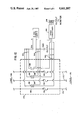
- FIG. 1 is a vertical elevation, partially broken away, of a fuse holder having a Hall-effect sensor arrangement
- FIG. 2 is a greatly enlarged detailed sectional view taken along the line 2--2 of FIG. 1;
- FIG. 3 is a side view of the detailed showing of FIG. 2;
- FIG. 4 is a longitudinal sectional view of one end of a fuse holder showing one form of current sensor arrangement
- FIG. 5 is a sectional view taken along the line 5--5 of FIG. 4;
- FIG. 6 is a view similar to FIG. 4 showing another form of sensor arrangement
- FIG. 7 is a sectional view taken along the line 7--7 of FIG. 6;
- FIG. 8 is a view similar to FIG. 4 showing still another form of sensor arrangement
- FIG. 9 is a sectional view taken along the line 9--9 of FIG. 8;
- FIG. 10 is a perspective view of a three phase fuse holder provided with a current sensor arrangement for each fuse;
- FIG. 11 is a sectional end view taken along the line 11--11 of FIG. 10;
- FIG. 12 is a circuit diagram of a fuse holder mounted current sensor arrangement for a three phase fuse holder.
- reference numeral 10 refers generally to a fuse holder of the type conventionally used to receive a cartridge type electrical circuit protection device or fuse 12.
- the fuse includes a cylindrical insulating body 14 and a pair of end caps 16, 18 defining spaced electrical terminals at the opposite ends thereof.
- the fuse holder comprises a mounting base 20 formed from a suitable dielectric material such as, for example, being molded from a thermosetting phenolic compound. Attached to the upper surface 22 of the fuse base are a pair of spaced apart fuse engaging clips 24,26. The clips are suitably attached to the upper surface 22 at locations such that they may be electrically conductively engaged with the spaced apart terminals 16, 18 of a fuse adapted to be mounted in the base. Each of the fuse clip elements 24, 26 has associated therewith an electrical connector each of which is electrically conductively attached to its associated fuse clip 24, 26, respectively. The connectors 28, 30 each serve to electrically cooperate with external conductors (not shown) thereby defining the path followed by electric current through the fuse base.
- each of the fuse clip/connector arrangements is of the type having a spring type fuse clip adapted to positively engage one of the cylindrical end caps of a fuse and a "box type" connector for providing the connection to the external wiring. While not shown specifically in the drawings it should be appreciated that each of the "box type” connectors is provided with a through opening extending horizontially therethrough as viewed in FIG. 1 to receive the bare end of a wire, the wire is then positively retained in the connector by engagement with the vertically extending set screws 32, 34 as shown in the drawing figure.
- the connector 30 and the fuse clip 26 are electrically interconnected by a flat section 36 of electrically conductive material providing the current path between the connector and the fuse clip.
- All metallic parts in such fuse holders are typically made of very high quality electrical copper and bronzes depending on the requirements of the particular fuse holder and in many cases may be provided with a protective plating on the outer surface thereof.
- the flat conductive interconnecting portion 36 defined above lies in substantially direct contact with the upper surface 22 of the fuse holder base 20.
- the fuse holder base in the region of the interconnecting strip 36, comprises a wall 37 of insulating material defining a substantially flat downwardly facing lower surface 38 which is substantially parallel to the upwardly facing surface 22 with which the interconnecting strip 36 is in confronting relation. It has been found that, when current is flowing through the fuse holder, the flow of current through the interconnecting strip 36 results in a particularly useful magnetic field therearound which may be sensed by a current sensing device positioned adjacent the downwardly facing surface 38 of the fuse base described above.
- the current sensor 40 comprises a Hall-effect device which is capable of providing an output voltage which is directly proportional to current flow through the flat interconnecting section 36.
- the invention comprises the incorporation in a fuse holder of a current sensing device capable of detecting the flow of current through some portion of the current path of the fuse holder.
- a current sensing device capable of detecting the flow of current through some portion of the current path of the fuse holder.
- current sensor means may be incorporated within a fuse holder anywhere along the "current path" of the fuse holder wherein sufficient magnetic flux is present, as a result of the flow of current through the fuse holder, to permit sensing of the magnetic field.
- a sensor of the type which may be broadly categorized as an "inductive type pick-up arrangement".
- such an inductive pick-up arrangement may comprise, by way of examples: a conductive wire extending parallel to the current path through the fuse holder; a rod of ferromagnetic material positioned in the mounting base in close proximity to the current path; or, a coil of wire such as for example a coil of enameled copper wire.
- Any of the above described simple inductive pick-up means is capable of having a current induced therein as a result of interaction with the magnetic field which is present along the current path through the fuse holder. Such induced current results in a useful signal which may then be processed to derive information relating to the current flow through the fuse holder.
- the signal or output voltage from the current sensing device may be detected and processed by a variety of electrical/electronic means to provide an indication of whether current is flowing through a fuse holder and the magnitude of such current flow.
- the output voltage from a fuse holder mounted current sensor has been used to power a visually ascertainable indicator mounted directly on the fuse holder base, such as an L.E.D. or an L.C.D.
- any fuse holder has a "current path" therethrough and the present invention is intended to include the incorporation of a current sensor in other types of fuse holders along such current path at a location wherein sufficient magnetic flux is present to enable interaction of a current sensor with the magnetic field surrounding a portion of the current path when current is passing through the fuse holder/fuse combination.
- FIGS. 4 and 5 a current sensor 42 making use of the inductive pick-up principle is illustrated wherein a coil 44 is positioned in the region underlying the fuse base upper surface 43 where it will be electromagnetically coupled with the magnetic field of the fuse base.
- the fuse holder base 46 is shown in a somewhat simplifed form from that of FIG. 1.
- the connector arrangement 48 for electrically cooperating with an external conductor is also shown in a simplified form.
- the current sensor 42 is positioned adjacent the downwardly facing surface 50 of the top wall of the fuse holder mounting base in a position in close proximity to a flat conductive strip 52 interconnecting the connector 48 and one of the fuse clips 54.
- the current sensor 42 comprises a bobbin 56 having a longitudinally extending opening therethrough through which an iron core 58 is suitably positioned and retained.
- the bobbin 56 is wound with a coil 44 thereupon defined by a plurality of circumfrential windings of a suitable enameled copper wire or the like.
- the number of windings defining the coil is dependent on the amperage rating of the fuse holder in which the coil is incorporated, a larger number of windings being necessary on lower amperage rating fuse holders in order to obtain the necessary output across the coil. As shown in FIG.
- the ends 60 of the coil are electrically connected with a suitable output connector 62 so that the signal induced across the output of the coil as a result of the electromagnetic coupling with the current through the fuse base may be readily accessed by whatever signal processing equipment the end user deems appropriate for his application.
- FIGS. 6 and 7 a modification of the current sensor arrangement of FIGS. 4 and 5 is shown.
- an opening 64 is provided in the top supporting wall 63 of the fuse base.
- the opening 64 passes from the upward surface 66 upon which the fuse clip 68 and connector 70 are mounted, through and into communication with the region underlying and adjacent the downwardly facing surface 72 of the wall 63.
- the flat section of electrically conductive material 74 which interconnects the fuse clip 68 and the connector 70 passses downwardly through the above described opening 64 and forms a loop 76 in the region adjacent the downwardly facing surface 72 and then passes upwardly again through the opening 64 back to a position adjacent to the upwardly facing surface 66.
- a current sensing arrangement 78 comprising a bobbin 80, iron core 82, and winding 84 of the type described hereinabove with respect to FIGS. 4 and 5.
- the loop 76 formed by the current carrying interconnecting member 74 around the bobbin/coil/core arrangement serves to concentrate the magnetic flux passing through the interconnecting member 74 in a manner enabling the arrangement to sense smaller currents passing along the current path than possible with the embodiment of FIGS. 4 and 5.
- the coil output leads 61 are connected directly to an indicator, comprising for example an L.C.D. or an L.E.D. 65 which is mounted directly on a side wall 67 of the base of the fuse holder.
- This indicator 65 provides a visually ascertainable display, carried directly by the fuse holder, responsive to the electric signal generated by the current sensor 78.
- FIGS. 8 and 9 another inductive type current sensor arrangement 86 is shown.
- the current carrying member 88 which interconnects the fuse clip 90 and the external connector 92, passes from the upper surface 94 of the fuse base 96 through an opening 98 therein to form a loop 100 adjacent the downwardly facing lower surface 102 of the support wall of the fuse holder.
- This embodiment is essentially a current transformer, in that a core 104 formed from a suitable ferromagnetic material such as iron passes through and encircles the loop 100 formed by the interconnecting member 88.
- the loop 100 formed by the interconnecting member 88 serves as the primary winding of the current transformer.
- the ends of the secondary winding 108 across which a useful signal is generated may be attached to a suitable output connector 110 to provide access by the end user.
- a direct indicating arrangement as shown in FIGS. 6 and 7 may be used.
- the Hall-effect sensor 40 is actually a magnetically responsive device which utilizes the Hall-effect for sensing a magnetic field.
- a Hall cell included in the device senses a magnetic field and provides an electrical output corresponding to the presence or absence of a magnetic field.
- Such a Hall-effect device is the Sprague UGN-3503U, which in addition to the Hall cell, includes an amplifier, trigger, and output stages integrated into a single monolithic chip.
- this Hall-effect device has an extremely small outer package dimension which facilitates positioning of the device in a variety of fuse holder configurations, particularly, smaller fuse holders having limited space available for mounting of a current sensing device.
- the Hall-effect device itself 40 is square and substantially flat and has three in-line pins providing input and output connections.
- One of the outer pins 112 is connected to a regulated DC power supply to provide a collector voltage to the output transistor of the Hall-effect device.
- the other of the outside pins 114 is the output pin at which the "Hall-voltage" is present when current is flowing through the fuse holder.
- the center pin 116 is a common ground for both the input voltage and the output or Hall voltage.
- the Hall-effect device 40 is supported in the desired position underlying the downwardly facing surface 38 of the wall 37 of the fuse holder base in close proximity to the current carrying, interconnecting strip 36 by a pair of L-shapped brackets 118.
- One leg 120 of each of the L-shapped brackets 118 is fixedly attached to the downwardly facing surface 38 of the wall 37 by suitable means such as for example a cyanoacrylate adhesive.
- the L-shaped brackets 118 are positioned so that the other legs 122 of the brackets extend downwardly from the surface 38 with the opposing faces 124 of the legs defining an air gap 126 therebetween.
- the air gap 126 is substantially the same thickness as the narrow dimensions of the Hall-effect device 40 and the device is adhesively attached to the faces 124 to retain it in the desired location within the air-gap.
- the position of the Hall-effect device 40 with respect to the interconnecting strip 36 may be easily controlled by selective positioning of the Hall-effect device 40 in the air gap 126 defined by the L-shaped brackets.
- the L-shaped brackets 118 are each fabricated from a ferromagnetic material which is capable of concentrating the magnetic field which surrounds the interconnecting strip 36, when current is flowing through the strip, into the air gap 126 and therefore in the region of the Hall-effect sensor 40.
- FIG. 1 the fuse holder mounting base 20 is shown sitting upon a rectangular metal box 128 comprising four side walls 130 and an upper wall 132.
- the four side walls 130 are substantially coextensive with the outer perimeter of the fuse holder mounting base 20 and the upper wall 132 interconnecting the upper edges of the four side walls is coextensive with the downwardly facing surface of the fuse base.
- a small opening 134 is provided in the upper wall 132 of the metal box 128 through which the three leads 136 associated with the Hall-effect sensor means 40 pass to their appropriate input/output terminals.
- the terminals 138 associated with the three outputs are located in one of the side walls 130 of the metal box and are indicated symbolically by a circle, triangle, and square in FIG. 1.
- the metal box 128 described hereinabove is made from a material which serves to shield the conductors 136 associated with the Hall-effect sensor 40 from the current path of the fuse holder. Accordingly, while the magnetic field surrounding a portion of the current path of the fuse holder is of the utmost importance to the sensing arrangement of the present invention it is desired to shield the inputs and outputs to the sensing means 40 from this magnetic field in order to avoid interference and crosstalk between the circuits.
- FIGS. 10 and 11 a three pole fuse holder 140 is shown which may be readily used to protect a three phase electrical supply system.
- Each of the three fuse holders 142 shown in these figures is substantially the same as that illustrated in FIG. 1. More specifically, each is supplied with its own current sensor arrangement 144 comprising a Hall-effect sensor 146 mounted to the downwardly facing surface 148 of the fuse holder base 150 by a magnetic field concentrating arrangement 152 as described in detail hereinabove.
- the three pole fuse holder 140 is mounted upon a rectangular shielding box 154 provided with three openings 156 in the top wall 158 thereof to permit passage into the box of the input/output leads 160 associated with the three separate Hall-effect current sensing arrangements 144.
- the input/output leads 160 pass to a suitable access panel 162 on one side 164 of the shield box 154.
- the inputs and outputs are identified as to which of the three fuse holders 142 they are associated with by an appropriate numbering or color-coded scheme. As shown in FIG. 10 a symbol system, as described above, may be used to identify the pin connection with which the connectors are associated.
- FIG. 12 is a circuit diagram of the invention as applied to a three phase fuse holder such as that shown in FIGS. 10 and 11.
- a three phase power source, "Line" 168 is applied to a three phase load 170 by three bus bars 172.
- a three phase fuse holder of the type shown in FIG. 10 and 11 which is represented generally by the dashed outline 174 is interposed between the power source 168 and load 170.
- the fuses, protecting the three phases are identified by the reference numerals 176, 178, and 180, and the portion of the current path of the three fuse holders to be sensed by the current sensors are identified respectively by the reference numerals 182, 184, and 186.
- each of the Hall-effect sensors is positioned adjacent each of the portions of the fuse holder current paths to be monitored. As discussed hereinabove each of the Hall-effect sensors has three leads associated with it. A first lead 190 providing an input voltage from a 5 volt regulated DC power supply, a second 192 providing the output for the Hall voltage, and a third lead 194 comprising a common ground for both input and output circuits.
- the output 192 from the three current sensing arrangements 188 is shown passing into a box 196 identified in the drawing as a signal conditioner wherein suitable well known electronic signal conditioning means may be employed to amplify and process the output signals and to generate appropriate outputs 198 for monitoring the condition of the three circuits.
- the monitor may comprise a visual display such as an L.E.D. or the like or, more sophisticated electronic circuitry may be used to derive further information from the output.
Abstract
Description
Claims (23)
Priority Applications (1)
| Application Number | Priority Date | Filing Date | Title |
|---|---|---|---|
| US06/659,974 US4661807A (en) | 1984-10-12 | 1984-10-12 | Electric fuse holder having an integral current sensor |
Applications Claiming Priority (1)
| Application Number | Priority Date | Filing Date | Title |
|---|---|---|---|
| US06/659,974 US4661807A (en) | 1984-10-12 | 1984-10-12 | Electric fuse holder having an integral current sensor |
Publications (1)
| Publication Number | Publication Date |
|---|---|
| US4661807A true US4661807A (en) | 1987-04-28 |
Family
ID=24647594
Family Applications (1)
| Application Number | Title | Priority Date | Filing Date |
|---|---|---|---|
| US06/659,974 Expired - Fee Related US4661807A (en) | 1984-10-12 | 1984-10-12 | Electric fuse holder having an integral current sensor |
Country Status (1)
| Country | Link |
|---|---|
| US (1) | US4661807A (en) |
Cited By (47)
| Publication number | Priority date | Publication date | Assignee | Title |
|---|---|---|---|---|
| US4784385A (en) * | 1987-02-20 | 1988-11-15 | Angelo Joseph M D | Aquatic exercising device |
| US5072327A (en) * | 1990-01-24 | 1991-12-10 | At&T Bell Laboratories | Electronic protection device for use with a fuse mount |
| US5093657A (en) * | 1989-11-29 | 1992-03-03 | Abb Power T&D Company | Distribution cutout condition sensor |
| US5923515A (en) * | 1998-01-27 | 1999-07-13 | Lucent Technologies Inc. | Battery protection fuse assembly |
| US6141202A (en) * | 1998-08-07 | 2000-10-31 | Daimlerchrysler Ag | Method and apparatus for triggering a fuse |
| EP1058283A2 (en) * | 1999-06-04 | 2000-12-06 | M. Schneider, Schaltgerätebau und Elektroinstallationen Gesellschaft m.b.H. | Monitoring system for low voltage switching devices |
| WO2002046777A2 (en) * | 2000-12-07 | 2002-06-13 | Lem Heme Limited | Current sensors |
| US6448897B1 (en) * | 2001-05-25 | 2002-09-10 | Glorytech Technology Co., Ltd | Fuse assembly having a warning or indicating device |
| US6472230B2 (en) * | 1999-10-13 | 2002-10-29 | International Business Machines Corporation | Re-settable tristate programmable device |
| EP1258838A2 (en) * | 2001-05-18 | 2002-11-20 | Markus R. Schneider | Device for current detection and use thereof |
| GB2376138A (en) * | 2001-05-29 | 2002-12-04 | Cooper Technologies Co | Magnetically actuated fuse indicator |
| US6577495B2 (en) * | 2000-12-15 | 2003-06-10 | Square D Company | Fuse base assembly |
| US6707688B2 (en) * | 2000-01-28 | 2004-03-16 | Hendry Mechanical Works | Electric apparatus with electric terminals and fused structures |
| US6741158B2 (en) * | 2002-07-18 | 2004-05-25 | Honeywell International Inc. | Magnetically sensed thermostat control |
| US20050024218A1 (en) * | 2003-07-28 | 2005-02-03 | Nikola Cuk | Fault monitoring apparatus and method |
| US20050231320A1 (en) * | 2004-04-20 | 2005-10-20 | Ackermann John M | Wireless communication fuse state indicator system and method |
| US20060077609A1 (en) * | 2004-09-10 | 2006-04-13 | Bender Robert L | System and method for circuit protector monitoring and management |
| US20060087397A1 (en) * | 2004-10-26 | 2006-04-27 | Cooper Technologies Company | Fuse state indicating optical circuit and system |
| US20060119463A1 (en) * | 2003-04-04 | 2006-06-08 | Katsuhiro Kubota | Fuse cavity structure and electric connection box |
| US20060199438A1 (en) * | 2005-02-15 | 2006-09-07 | Server Technology, Inc. | Ganged electrical outlets, apparatus, and methods of use |
| US20070053127A1 (en) * | 2005-02-18 | 2007-03-08 | Dobbs Eugene F | Apparatus comprising circuit breaker with adjunct sensor unit |
| US20070159752A1 (en) * | 2006-01-11 | 2007-07-12 | Server Technology, Inc. | Fuse module with removable fuse carrier for fused electrical device |
| US20070194942A1 (en) * | 2004-09-10 | 2007-08-23 | Darr Matthew R | Circuit protector monitoring assembly, system and method |
| US20070257807A1 (en) * | 2004-09-10 | 2007-11-08 | Darr Matthew R | Circuit protector monitoring assembly |
| US7301432B1 (en) * | 2005-01-11 | 2007-11-27 | Tii Network Technologies, Inc. | Fusing terminal device |
| WO2007051165A3 (en) * | 2005-10-27 | 2008-06-12 | Charles L Manto | System and method for providing certifiable electromagnetic pulse and rfi protection through mass-produced shielded containers and rooms |
| US20080231410A1 (en) * | 2004-04-20 | 2008-09-25 | Frank Anthony Doljack | RFID Open Fuse Indicator, System, and Method |
| US20090061691A1 (en) * | 2006-01-11 | 2009-03-05 | Server Technology, Inc. | Fuse module with movable fuse holder for fused electrical device |
| US20090180241A1 (en) * | 2006-01-11 | 2009-07-16 | Server Technology, Inc. | Power distribution unit and methods of making and use including modular construction and assemblies |
| US20090184797A1 (en) * | 2007-11-14 | 2009-07-23 | Enerdel, Inc., | Fuse assembly with integrated current sensing |
| US20100033294A1 (en) * | 2008-08-06 | 2010-02-11 | Wen-Tsung Cheng | Fuse seat with prompting function |
| US20100033293A1 (en) * | 2008-08-06 | 2010-02-11 | Wen-Tsung Cheng | Fuse assembly with a capability of indicating a fusing state by light |
| US20100066351A1 (en) * | 2004-12-20 | 2010-03-18 | Johnson Controls Technology Company | Device for measuring a current flowing in a cable |
| US7772959B2 (en) * | 2008-08-06 | 2010-08-10 | Wen-Tsung Cheng | Fuse seat having light-emitting module of hidden type |
| US20110163839A1 (en) * | 2010-01-06 | 2011-07-07 | Wen-Tsung Cheng | Fuse structure with power disconnection light indicating function |
| US20130303030A1 (en) * | 2012-04-24 | 2013-11-14 | Arteche Lantegi Elkartea, S.A. | High-voltage connector |
| US20130329332A1 (en) * | 2012-06-07 | 2013-12-12 | Austin J. Funcheon | Power line indicator accessory for fusible circuit protection device array |
| US20150014129A1 (en) * | 2013-07-12 | 2015-01-15 | Eaton Corporation | Fuse and trip mechanism therefor |
| US9099270B2 (en) | 2011-05-23 | 2015-08-04 | Tlz Creative Solutions Llc | Pole mounted fuse cutout indicator |
| EP2985779A1 (en) * | 2014-08-13 | 2016-02-17 | Pronutec, S.A.U. | Fuseholder base |
| US20160284501A1 (en) * | 2015-03-23 | 2016-09-29 | Cooper Technologies Company | High voltage compact fuse assembly with magnetic arc deflection |
| US20170263406A1 (en) * | 2016-03-14 | 2017-09-14 | IoT Sensor Corporation | Fuse Cutout Monitoring and Indication Device |
| US10180447B2 (en) | 2015-07-20 | 2019-01-15 | Eaton Intelligent Power Limited | Electric fuse current sensing systems and monitoring methods |
| US10854414B2 (en) | 2016-05-11 | 2020-12-01 | Eaton Intelligent Power Limited | High voltage electrical disconnect device with magnetic arc deflection assembly |
| US11133144B2 (en) * | 2018-08-10 | 2021-09-28 | Siemens Aktiengesellschaft | Fuse, fuse body, system and method |
| US11143718B2 (en) | 2018-05-31 | 2021-10-12 | Eaton Intelligent Power Limited | Monitoring systems and methods for estimating thermal-mechanical fatigue in an electrical fuse |
| US11289298B2 (en) | 2018-05-31 | 2022-03-29 | Eaton Intelligent Power Limited | Monitoring systems and methods for estimating thermal-mechanical fatigue in an electrical fuse |
Citations (13)
| Publication number | Priority date | Publication date | Assignee | Title |
|---|---|---|---|---|
| US2036223A (en) * | 1930-06-13 | 1936-04-07 | Westinghouse Electric & Mfg Co | Means for indicating the blowing of high-tension fuses |
| US3056922A (en) * | 1960-04-26 | 1962-10-02 | W W Henry Co Inc | Exposure totalizer |
| US3138742A (en) * | 1962-02-13 | 1964-06-23 | Jr Edmund O Schweitzer | Means for measuring current flow in and voltage of a high voltage alternating current conductor |
| US3158713A (en) * | 1963-05-22 | 1964-11-24 | Margulies Gerald | Apparatus for indicating an open electrical circuit |
| US3174011A (en) * | 1961-09-25 | 1965-03-16 | Borys Emil | Cartridge fuse holder with indicator |
| US3225163A (en) * | 1961-03-28 | 1965-12-21 | Ulle C Linton | Indicator fuseholder with current responsive device |
| US3457535A (en) * | 1966-11-15 | 1969-07-22 | Fuse Indicator Corp | Blown fuse indicator |
| US3546692A (en) * | 1968-12-16 | 1970-12-08 | Chase Shawmut Co | Combined optical and acoustical blown fuse indicator |
| US3794948A (en) * | 1970-10-02 | 1974-02-26 | Fuse Indicator Corp | Blown fuse indicators |
| US4286213A (en) * | 1979-03-19 | 1981-08-25 | Research Products Corporation | Energy sensor |
| US4506214A (en) * | 1977-07-08 | 1985-03-19 | Lgz Landis & Gyr Zug Ag | Measuring transformer |
| US4525669A (en) * | 1982-12-20 | 1985-06-25 | Sangamo Weston, Inc. | Power measurement in an electrical distribution system having three or more wires |
| US4558310A (en) * | 1982-09-29 | 1985-12-10 | Mcallise Raymond J | Current sensing device and monitor |
-
1984
- 1984-10-12 US US06/659,974 patent/US4661807A/en not_active Expired - Fee Related
Patent Citations (13)
| Publication number | Priority date | Publication date | Assignee | Title |
|---|---|---|---|---|
| US2036223A (en) * | 1930-06-13 | 1936-04-07 | Westinghouse Electric & Mfg Co | Means for indicating the blowing of high-tension fuses |
| US3056922A (en) * | 1960-04-26 | 1962-10-02 | W W Henry Co Inc | Exposure totalizer |
| US3225163A (en) * | 1961-03-28 | 1965-12-21 | Ulle C Linton | Indicator fuseholder with current responsive device |
| US3174011A (en) * | 1961-09-25 | 1965-03-16 | Borys Emil | Cartridge fuse holder with indicator |
| US3138742A (en) * | 1962-02-13 | 1964-06-23 | Jr Edmund O Schweitzer | Means for measuring current flow in and voltage of a high voltage alternating current conductor |
| US3158713A (en) * | 1963-05-22 | 1964-11-24 | Margulies Gerald | Apparatus for indicating an open electrical circuit |
| US3457535A (en) * | 1966-11-15 | 1969-07-22 | Fuse Indicator Corp | Blown fuse indicator |
| US3546692A (en) * | 1968-12-16 | 1970-12-08 | Chase Shawmut Co | Combined optical and acoustical blown fuse indicator |
| US3794948A (en) * | 1970-10-02 | 1974-02-26 | Fuse Indicator Corp | Blown fuse indicators |
| US4506214A (en) * | 1977-07-08 | 1985-03-19 | Lgz Landis & Gyr Zug Ag | Measuring transformer |
| US4286213A (en) * | 1979-03-19 | 1981-08-25 | Research Products Corporation | Energy sensor |
| US4558310A (en) * | 1982-09-29 | 1985-12-10 | Mcallise Raymond J | Current sensing device and monitor |
| US4525669A (en) * | 1982-12-20 | 1985-06-25 | Sangamo Weston, Inc. | Power measurement in an electrical distribution system having three or more wires |
Cited By (90)
| Publication number | Priority date | Publication date | Assignee | Title |
|---|---|---|---|---|
| US4784385A (en) * | 1987-02-20 | 1988-11-15 | Angelo Joseph M D | Aquatic exercising device |
| US5093657A (en) * | 1989-11-29 | 1992-03-03 | Abb Power T&D Company | Distribution cutout condition sensor |
| US5072327A (en) * | 1990-01-24 | 1991-12-10 | At&T Bell Laboratories | Electronic protection device for use with a fuse mount |
| US5923515A (en) * | 1998-01-27 | 1999-07-13 | Lucent Technologies Inc. | Battery protection fuse assembly |
| US6141202A (en) * | 1998-08-07 | 2000-10-31 | Daimlerchrysler Ag | Method and apparatus for triggering a fuse |
| EP1058283A3 (en) * | 1999-06-04 | 2003-03-12 | M. Schneider, Schaltgerätebau und Elektroinstallationen Gesellschaft m.b.H. | Monitoring system for low voltage switching devices |
| EP1058283A2 (en) * | 1999-06-04 | 2000-12-06 | M. Schneider, Schaltgerätebau und Elektroinstallationen Gesellschaft m.b.H. | Monitoring system for low voltage switching devices |
| US6472230B2 (en) * | 1999-10-13 | 2002-10-29 | International Business Machines Corporation | Re-settable tristate programmable device |
| US7495932B2 (en) | 2000-01-28 | 2009-02-24 | Reyes Jeremiah G | Electric apparatus with electric terminals and fused structures |
| US20050258929A1 (en) * | 2000-01-28 | 2005-11-24 | Hendry Mechanical Works | Electric apparatus with electric terminals and fused structures |
| US6707688B2 (en) * | 2000-01-28 | 2004-03-16 | Hendry Mechanical Works | Electric apparatus with electric terminals and fused structures |
| WO2002046777A2 (en) * | 2000-12-07 | 2002-06-13 | Lem Heme Limited | Current sensors |
| WO2002046777A3 (en) * | 2000-12-07 | 2003-01-09 | Lem Heme Ltd | Current sensors |
| US6577495B2 (en) * | 2000-12-15 | 2003-06-10 | Square D Company | Fuse base assembly |
| EP1258838A2 (en) * | 2001-05-18 | 2002-11-20 | Markus R. Schneider | Device for current detection and use thereof |
| EP1258838A3 (en) * | 2001-05-18 | 2004-09-15 | Markus R. Schneider | Device for current detection and use thereof |
| US6448897B1 (en) * | 2001-05-25 | 2002-09-10 | Glorytech Technology Co., Ltd | Fuse assembly having a warning or indicating device |
| GB2376138A (en) * | 2001-05-29 | 2002-12-04 | Cooper Technologies Co | Magnetically actuated fuse indicator |
| US6741158B2 (en) * | 2002-07-18 | 2004-05-25 | Honeywell International Inc. | Magnetically sensed thermostat control |
| US7612646B2 (en) * | 2003-04-04 | 2009-11-03 | Yazaki Corporation | Fuse cavity structure and electric connection box |
| US20060119463A1 (en) * | 2003-04-04 | 2006-06-08 | Katsuhiro Kubota | Fuse cavity structure and electric connection box |
| US20050024218A1 (en) * | 2003-07-28 | 2005-02-03 | Nikola Cuk | Fault monitoring apparatus and method |
| US7109877B2 (en) * | 2003-07-28 | 2006-09-19 | Nikola Cuk | Fault monitoring apparatus and method |
| US8134445B2 (en) * | 2004-04-20 | 2012-03-13 | Cooper Technologies Company | RFID open fuse indicator, system, and method |
| US20050231320A1 (en) * | 2004-04-20 | 2005-10-20 | Ackermann John M | Wireless communication fuse state indicator system and method |
| US20080231410A1 (en) * | 2004-04-20 | 2008-09-25 | Frank Anthony Doljack | RFID Open Fuse Indicator, System, and Method |
| US7369029B2 (en) | 2004-04-20 | 2008-05-06 | Cooper Technologies Company | Wireless communication fuse state indicator system and method |
| US7576635B2 (en) | 2004-09-10 | 2009-08-18 | Cooper Technologies Company | Circuit protector signal transmission, methods and system |
| US20060077609A1 (en) * | 2004-09-10 | 2006-04-13 | Bender Robert L | System and method for circuit protector monitoring and management |
| US8169331B2 (en) | 2004-09-10 | 2012-05-01 | Cooper Technologies Company | Circuit protector monitoring assembly |
| US8059005B2 (en) * | 2004-09-10 | 2011-11-15 | Cooper Technologies Company | Circuit protector monitoring assembly kit and method |
| US20070194942A1 (en) * | 2004-09-10 | 2007-08-23 | Darr Matthew R | Circuit protector monitoring assembly, system and method |
| US20070257807A1 (en) * | 2004-09-10 | 2007-11-08 | Darr Matthew R | Circuit protector monitoring assembly |
| US7612654B2 (en) | 2004-09-10 | 2009-11-03 | Cooper Technologies Company | System and method for circuit protector monitoring and management |
| US20060077607A1 (en) * | 2004-09-10 | 2006-04-13 | Henricks Michael C | Circuit protector monitoring assembly kit and method |
| US20060077608A1 (en) * | 2004-09-10 | 2006-04-13 | Speno Timothy H | Multifunctional response tool, method and system for circuit protector management |
| US7391299B2 (en) | 2004-09-10 | 2008-06-24 | Cooper Technologies Company | Circuit protector monitoring and management system user interface method, system and program |
| US20060087785A1 (en) * | 2004-09-10 | 2006-04-27 | Bender Robert L | Circuit protector signal transmission, methods and system |
| US20060087397A1 (en) * | 2004-10-26 | 2006-04-27 | Cooper Technologies Company | Fuse state indicating optical circuit and system |
| US20100066351A1 (en) * | 2004-12-20 | 2010-03-18 | Johnson Controls Technology Company | Device for measuring a current flowing in a cable |
| US8242772B2 (en) | 2004-12-20 | 2012-08-14 | Johnson Controls Technology Company | Device for measuring a current flowing in a cable |
| US8142237B2 (en) * | 2004-12-20 | 2012-03-27 | Johnson Controls Technology Company | Device for measuring a current flowing in a cable |
| US20110062945A1 (en) * | 2004-12-20 | 2011-03-17 | Johnson Controls Technology Company | Device for measuring a current flowing in a cable |
| US7301432B1 (en) * | 2005-01-11 | 2007-11-27 | Tii Network Technologies, Inc. | Fusing terminal device |
| US20070128927A1 (en) * | 2005-02-15 | 2007-06-07 | Server Technology, Inc. | Ganged electrical outlets, apparatus, and methods of use |
| US20060199438A1 (en) * | 2005-02-15 | 2006-09-07 | Server Technology, Inc. | Ganged electrical outlets, apparatus, and methods of use |
| US7905749B2 (en) | 2005-02-15 | 2011-03-15 | Server Technology, Inc. | Ganged electrical outlets, apparatus, and methods of use |
| US20070053127A1 (en) * | 2005-02-18 | 2007-03-08 | Dobbs Eugene F | Apparatus comprising circuit breaker with adjunct sensor unit |
| US7423858B2 (en) | 2005-02-18 | 2008-09-09 | Airpax Corporation | Apparatus comprising circuit breaker with adjunct sensor unit |
| WO2007051165A3 (en) * | 2005-10-27 | 2008-06-12 | Charles L Manto | System and method for providing certifiable electromagnetic pulse and rfi protection through mass-produced shielded containers and rooms |
| US20070159752A1 (en) * | 2006-01-11 | 2007-07-12 | Server Technology, Inc. | Fuse module with removable fuse carrier for fused electrical device |
| US9287688B2 (en) | 2006-01-11 | 2016-03-15 | Server Technology, Inc. | Power distribution unit and methods of making and use including modular construction and assemblies |
| US7706134B2 (en) | 2006-01-11 | 2010-04-27 | Server Technology, Inc. | Power distribution unit and methods of making and use including modular construction and assemblies |
| US7742284B2 (en) * | 2006-01-11 | 2010-06-22 | Server Technology, Inc. | Fuse module with movable fuse holder for fused electrical device |
| US20090061691A1 (en) * | 2006-01-11 | 2009-03-05 | Server Technology, Inc. | Fuse module with movable fuse holder for fused electrical device |
| US20090180241A1 (en) * | 2006-01-11 | 2009-07-16 | Server Technology, Inc. | Power distribution unit and methods of making and use including modular construction and assemblies |
| US7675739B2 (en) | 2006-01-11 | 2010-03-09 | Server Technology, Inc. | Fuse module with removable fuse carrier for fused electrical device |
| US20090184797A1 (en) * | 2007-11-14 | 2009-07-23 | Enerdel, Inc., | Fuse assembly with integrated current sensing |
| US7969275B2 (en) * | 2007-11-14 | 2011-06-28 | Enerdel, Inc. | Fuse assembly with integrated current sensing |
| US20100033294A1 (en) * | 2008-08-06 | 2010-02-11 | Wen-Tsung Cheng | Fuse seat with prompting function |
| US7839258B2 (en) * | 2008-08-06 | 2010-11-23 | Wen-Tsung Cheng | Fuse assembly with a capability of indicating a fusing state by light |
| US7772959B2 (en) * | 2008-08-06 | 2010-08-10 | Wen-Tsung Cheng | Fuse seat having light-emitting module of hidden type |
| US20100033293A1 (en) * | 2008-08-06 | 2010-02-11 | Wen-Tsung Cheng | Fuse assembly with a capability of indicating a fusing state by light |
| US20110163839A1 (en) * | 2010-01-06 | 2011-07-07 | Wen-Tsung Cheng | Fuse structure with power disconnection light indicating function |
| US8164411B2 (en) * | 2010-01-06 | 2012-04-24 | Wen-Tsung Cheng | Fuse structure with power disconnection light indicating function |
| US9099270B2 (en) | 2011-05-23 | 2015-08-04 | Tlz Creative Solutions Llc | Pole mounted fuse cutout indicator |
| US20130303030A1 (en) * | 2012-04-24 | 2013-11-14 | Arteche Lantegi Elkartea, S.A. | High-voltage connector |
| US9209575B2 (en) * | 2012-04-24 | 2015-12-08 | Arteche Lantegi Elkartea, S.A. | High-voltage connector |
| US9170293B2 (en) * | 2012-06-07 | 2015-10-27 | Cooper Technologies Company | Power line indicator accessory for fusible circuit protection device array |
| US20130329332A1 (en) * | 2012-06-07 | 2013-12-12 | Austin J. Funcheon | Power line indicator accessory for fusible circuit protection device array |
| US9490093B2 (en) * | 2013-07-12 | 2016-11-08 | Eaton Corporation | Fuse and trip mechanism therefor |
| US10147574B2 (en) | 2013-07-12 | 2018-12-04 | Eaton Intelligent Power Limited | Fuse and trip mechanism therefor |
| US20150014129A1 (en) * | 2013-07-12 | 2015-01-15 | Eaton Corporation | Fuse and trip mechanism therefor |
| CN107004532A (en) * | 2014-08-13 | 2017-08-01 | 普洛纽泰克独资有限公司 | Vertical fuse keeper matrix |
| AU2015303065B2 (en) * | 2014-08-13 | 2020-07-16 | Pronutec, S.A.U. | Vertical fuse-carrying base |
| WO2016024033A1 (en) * | 2014-08-13 | 2016-02-18 | Pronutec, S.A.U. | Vertical fuse-carrying base |
| CN107004532B (en) * | 2014-08-13 | 2020-08-07 | 普洛纽泰克独资有限公司 | Vertical fuse holder base |
| EP2985779A1 (en) * | 2014-08-13 | 2016-02-17 | Pronutec, S.A.U. | Fuseholder base |
| US9601297B2 (en) * | 2015-03-23 | 2017-03-21 | Cooper Technologies Company | High voltage compact fuse assembly with magnetic arc deflection |
| US20170103866A1 (en) * | 2015-03-23 | 2017-04-13 | Cooper Technologies Company | High voltage compact fuse assembly with magnetic arc deflection |
| US20160284501A1 (en) * | 2015-03-23 | 2016-09-29 | Cooper Technologies Company | High voltage compact fuse assembly with magnetic arc deflection |
| US9899180B2 (en) * | 2015-03-23 | 2018-02-20 | Cooper Technologies Company | High voltage compact fuse assembly with magnetic arc deflection |
| US10180447B2 (en) | 2015-07-20 | 2019-01-15 | Eaton Intelligent Power Limited | Electric fuse current sensing systems and monitoring methods |
| US10598703B2 (en) | 2015-07-20 | 2020-03-24 | Eaton Intelligent Power Limited | Electric fuse current sensing systems and monitoring methods |
| US20170263406A1 (en) * | 2016-03-14 | 2017-09-14 | IoT Sensor Corporation | Fuse Cutout Monitoring and Indication Device |
| US10102995B2 (en) * | 2016-03-14 | 2018-10-16 | IoT Sensor Corporation | Fuse cutout monitoring and indication device |
| US10854414B2 (en) | 2016-05-11 | 2020-12-01 | Eaton Intelligent Power Limited | High voltage electrical disconnect device with magnetic arc deflection assembly |
| US11143718B2 (en) | 2018-05-31 | 2021-10-12 | Eaton Intelligent Power Limited | Monitoring systems and methods for estimating thermal-mechanical fatigue in an electrical fuse |
| US11289298B2 (en) | 2018-05-31 | 2022-03-29 | Eaton Intelligent Power Limited | Monitoring systems and methods for estimating thermal-mechanical fatigue in an electrical fuse |
| US11133144B2 (en) * | 2018-08-10 | 2021-09-28 | Siemens Aktiengesellschaft | Fuse, fuse body, system and method |
Similar Documents
| Publication | Publication Date | Title |
|---|---|---|
| US4661807A (en) | Electric fuse holder having an integral current sensor | |
| US4616207A (en) | Electric fuse holder having a Hall-effect current sensor | |
| US6348800B1 (en) | Multi-phase ground fault current sensor system | |
| CA2181578C (en) | Magnetic sensors | |
| US6441605B1 (en) | Current sensor for an electrical device | |
| US20130293989A1 (en) | Apparatus and method for arc fault detection | |
| KR960012057A (en) | Trip device including one or more current transformers | |
| US5014043A (en) | Current sensing | |
| US6094043A (en) | ARC detection sensor utilizing discrete inductors | |
| AU706638B2 (en) | Current sensor and electrical apparatus including it | |
| US3950677A (en) | Housing mounting arrangement for ground fault circuit interrupter | |
| EP0689271B1 (en) | An earth leakage unit | |
| US5017877A (en) | Watthour meter open potential circuit detecting device | |
| US6414579B1 (en) | Current transformer and method for correcting asymmetries therein | |
| US6404180B1 (en) | Technique for sensing current in a conductor with reduced susceptibility to electrical noise on the conductor | |
| US4249126A (en) | On-line fault locator for gas-insulated conductors with plural detectors | |
| US5382896A (en) | Measuring assembly with current sensor and supply transformer | |
| WO2019216511A1 (en) | Rogowski coil current sensor having shielding structure | |
| US3443158A (en) | Fault current recorder and indicator for electrical circuits | |
| JPH04320971A (en) | Current detector | |
| JPH07260830A (en) | Current-detecting apparatus | |
| JPH06289059A (en) | Current detector | |
| CA1048600A (en) | Ground fault circuit interrupting module | |
| KR20010027246A (en) | An alternating current sensor and electric power instrument including it | |
| JPS59501838A (en) | Inductive length and angle measuring device |
Legal Events
| Date | Code | Title | Description |
|---|---|---|---|
| AS | Assignment |
Owner name: GOULD, INC., 10 GOULD CENTER ROLLING MEADOWS, IL Free format text: ASSIGNMENT OF ASSIGNORS INTEREST.;ASSIGNOR:PANARO, ROBERT J.;REEL/FRAME:004325/0309 Effective date: 19841009 |
|
| FEPP | Fee payment procedure |
Free format text: PAYOR NUMBER ASSIGNED (ORIGINAL EVENT CODE: ASPN); ENTITY STATUS OF PATENT OWNER: LARGE ENTITY |
|
| FEPP | Fee payment procedure |
Free format text: PAYER NUMBER DE-ASSIGNED (ORIGINAL EVENT CODE: RMPN); ENTITY STATUS OF PATENT OWNER: LARGE ENTITY Free format text: PAYOR NUMBER ASSIGNED (ORIGINAL EVENT CODE: ASPN); ENTITY STATUS OF PATENT OWNER: LARGE ENTITY |
|
| FPAY | Fee payment |
Year of fee payment: 4 |
|
| AS | Assignment |
Owner name: GOULD ELECTRONICS INC., OHIO Free format text: ASSIGNMENT OF ASSIGNORS INTEREST;ASSIGNOR:GOULD INC.;REEL/FRAME:006865/0444 Effective date: 19940131 |
|
| REMI | Maintenance fee reminder mailed | ||
| LAPS | Lapse for failure to pay maintenance fees | ||
| FP | Lapsed due to failure to pay maintenance fee |
Effective date: 19950503 |
|
| STCH | Information on status: patent discontinuation |
Free format text: PATENT EXPIRED DUE TO NONPAYMENT OF MAINTENANCE FEES UNDER 37 CFR 1.362 |