US4656447A - Superconducting filter coils for high homogeneity magnetic field - Google Patents
Superconducting filter coils for high homogeneity magnetic field Download PDFInfo
- Publication number
- US4656447A US4656447A US06/625,076 US62507684A US4656447A US 4656447 A US4656447 A US 4656447A US 62507684 A US62507684 A US 62507684A US 4656447 A US4656447 A US 4656447A
- Authority
- US
- United States
- Prior art keywords
- coil
- coils
- magnetic field
- magnet
- filter
- Prior art date
- Legal status (The legal status is an assumption and is not a legal conclusion. Google has not performed a legal analysis and makes no representation as to the accuracy of the status listed.)
- Expired - Lifetime
Links
Images

Classifications
-
- G—PHYSICS
- G01—MEASURING; TESTING
- G01R—MEASURING ELECTRIC VARIABLES; MEASURING MAGNETIC VARIABLES
- G01R33/00—Arrangements or instruments for measuring magnetic variables
- G01R33/20—Arrangements or instruments for measuring magnetic variables involving magnetic resonance
- G01R33/28—Details of apparatus provided for in groups G01R33/44 - G01R33/64
- G01R33/38—Systems for generation, homogenisation or stabilisation of the main or gradient magnetic field
- G01R33/387—Compensation of inhomogeneities
- G01R33/3875—Compensation of inhomogeneities using correction coil assemblies, e.g. active shimming
-
- Y—GENERAL TAGGING OF NEW TECHNOLOGICAL DEVELOPMENTS; GENERAL TAGGING OF CROSS-SECTIONAL TECHNOLOGIES SPANNING OVER SEVERAL SECTIONS OF THE IPC; TECHNICAL SUBJECTS COVERED BY FORMER USPC CROSS-REFERENCE ART COLLECTIONS [XRACs] AND DIGESTS
- Y10—TECHNICAL SUBJECTS COVERED BY FORMER USPC
- Y10S—TECHNICAL SUBJECTS COVERED BY FORMER USPC CROSS-REFERENCE ART COLLECTIONS [XRACs] AND DIGESTS
- Y10S505/00—Superconductor technology: apparatus, material, process
- Y10S505/825—Apparatus per se, device per se, or process of making or operating same
- Y10S505/879—Magnet or electromagnet
Definitions
- the present invention relates to magnets and similar means for producing highly uniform, high strength magnetic fields. More particularly, the present invention is related to the construction of magnets for producing high homogeneity magnetic fields for use in nuclear magnetic resonance (NMR) imaging systems.
- NMR nuclear magnetic resonance
- B p O in the volume of interest.
- the magnetic field is important since it establishes nuclear spin precession distribution in the subject volume. Subsequent radio frequency radiation from excited nuclei in this volume are employed, under appropriate circumstances, to produce imaging data and spectroscopic chemical information corresponding to physical objects and processes placed within the volume of interest.
- NMR imaging is particularly applicable to the generation of medical diagnostic images.
- it has been found that it is particularly desirable to employ a highly uniform magnetic field.
- the use of superconductive materials for the construction of high strength, high homogeneity magnets is particularly advantageous.
- superconductive properties may be exploited to provide magnet coils carrying high, persistent currents, often at a level of between about 1,000 and 2,000 amperes.
- the use of superconductive materials has permitted the construction of a magnet for NMR imaging which produces a magnetic field of approximately 1.5 Tesla (15,000 gauss). These high field strengths are particularly advantageous in that the signal to noise ratio in the NMR imaging system is improved.
- superconductive magnets do not require the supply of constant power as do conventional resistive magnets. Furthermore, the important properties of field homogeneity and stability can be better maintained with superconductive magnets than with resistively excited magnet devices. Accordingly, it is seen that it is highly desirable to be able to produce high strength, high uniformity magnetic fields.
- superconductive magnets employed for NMR imaging also typically employ a set of correction coils for the purpose of achieving greater magnetic field uniformity.
- One or more sets of these correction coils may be required.
- the field contribution of a correction coil is designed to be nonuniform, so that in combination with the main magnetic field, the field of the correction coil acts to reduce overall magnetic field non-uniformity.
- Correction coils are typically designed to carry only a small fraction of the current carried by the main superconductive coils. This is a natural consequence of the fact that the correction coils are only designed for producing small correction fields to counter-balance main coil field non-uniformity.
- both the main coils and the correction coils are superconducting
- persistent current switches which are devices which short circuit the coils with an element which is superconductive or resistive at the operator's discretion.
- the switches can be changed to the superconductive state (persistent mode), and the system of coils thereafter preserves its adjustment until it is intentionally disturbed. It should be kept in mind that high field uniformity is an important aspect of the present invention.
- the fundamental method is to distribute the coils so that individually or collectively, they are coupled only to a specific term or specific terms in a series expansion of the field, and that consequently they act to eliminate the specific term or terms.
- a preferred embodiment for the present invention comprises a set of main coils disposed substantially on the surface of a cylindrical support and producing a substantially uniform magnetic field within the support volume, together with at least one short circuited superconducting filter coil, disposed substantially on the surface of a cylindrical support and being disposed so as to reduce specific terms in the cylindrical expansion series representing deviation from magnetic field uniformity.
- at least one of the filter coils is wound so that the surface turn density associated with it is given by sinusoidal or cosinusoidal function of the axial distance from the central area of the cylindrical support.
- an object of the present invention is to provide high strength, high homogeneity magnetic fields.
- FIG. 1 is an isometric view illustrating a cylindrical volume of length L and radius R, useful for understanding field expansions in terms of cylindrical coordinates;
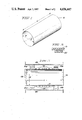
- FIG. 2 is a cross-sectional side elevation view illustrating a magnet in accordance with a preferred embodiment of the present invention
- FIG. 3 is a cross-sectional side elevation view illustrating in detail a cross-section through a filter coil winding and a portion of the cylindrical support form.
- FIG. 4 is an isometric view illustrating a set of transverse saddle coils having turns density distributions which are continuously variable in both the axial and circumferential directions.
- FIG. 5 is a flat plan view of the saddle coils of FIG. 4 and their connection prior to their being wrapped onto a cylindrical coil form.
- FIG. 2 illustrates a magnet for NMR imaging in accordance with one embodiment of the present invention.
- Metal end caps 11a and 11b shown in FIG. 2 are illustrated primarily for the purpose of explaining the theoretical development of the present invention. These end caps are not contemplated as generally being present in NMR imaging systems however.
- the general principle upon which the present invention is based is that closed loop, or short-circuited superconducting coils operate to preserve the net flux linkage through themselves. Advantage is taken of this property to construct specific coils to modify the magnetic field produced by the main coils in order to provide a more spacially uniform magnetic field. As discussed above, spacial uniformity is highly desirable in NMR imaging systems.
- the magnet coil assembly of FIG. 2 particularly illustrates the presence of main coils 30a and 30b for providing the greatest contribution to the axially directed magnetic field. Main coils 30a and 30b may or may not, in general, be superconductive. However, it is generally preferred that they are so. Not apparent from FIG.
- coil set 20 is the most relevant aspect of FIG. 2.
- coil 20 comprises a superconductive coil disposed in a closed loop, that is, short-circuited condition. While a specific short-circuiting connection is not illustrated in FIG. 2, it is generally understood that such a connection can be made at any convenient location with a super-conductive wire running parallel to the axis of the cylinder. It should also be specifically noted that the axial winding density distribution for coil 20 is not linear.
- FIG. 2 illustrates an embodiment of the present invention in which the winding density distribution is (co)sinusoidal.
- the superconductive components illustrated in FIG. 2 are typically disposed within a cryostat structure to contain the coolant and to thermally insulate the structure from ambient temperature conditions.
- cryostat structures are well known and form no part of the present invention, these structures are not shown in the figures.
- FIG. 2 illustrates the presence of only a single filter coil on a single cylindrical form, it may be generally desirable to employ several such filter coils on distinct supporting forms. Each such filter coil is designed to eliminate a specific term in an orthogonal function expansion representing deviation of the axial component of the interior magnetic field from spatial uniformity.
- the operation of the apparatus shown in FIG. 2 typically takes place in the following manner.
- Superconductive winding set 20 is made to enter the superconductive state by appropriate cooling. The state transition occurs with zero flux through the area bounded by the windings. This area is seen to be approximately ⁇ R 2 .
- design current levels are established in the main coils. These coils are preferably superconductive. In accordance with well understood mechanisms this current is established with the use of a persistent current switch which comprises superconductive material which may be switched from the resistive or ohmic state to the superconductive state at the will of the operator. It is however understood that time delays in switching occur as a consequence of the thermal nature of the switch.
- Such switches are conventionally connected across the main superconductive windings along with a DC current source. Once the desired current level is reached in the main coil the switch is changed to the superconductive state thereby establishing a closed superconducting loop. The power supply may then be removed.
- filter coil 20 of the present invention is itself a short-circuited loop and there is no need to include a persistent current switch in the filter coil circuit. Accordingly, current flowing in coil 20 arises out of its inductive coupling with the magnetic field flux produced by the main coils. Accordingly, since filter coil 20 is designed for carrying corrective currents to improve magnetic field homogeneity, it need not be designed to carry high levels of current.
- filter coil 20 is now considered, in order to appreciate the particular construction details of filter coils. It should also be born in mind that, while FIG. 2 illustrates the utilization of only a single filter coil, additional filter coils may also be employed to correct particular forms of magnetic field inhomogeneity. These particular forms are described in terms of magnetic field expansion series, as is more particularly described below.
- a set of individual superconducting filter coils is defined herein as a set of coils each of which is coupled to one specific term and consequently acts to eliminate that one term in a series expansion of the imposed field, without effect on the other terms of the expansion.
- a set of group superconducting filter coils is also defined as a set of n coils which are collectively coupled to only a specific group of n terms in the expansion and consequently act to eliminate those n terms in the imposed field expansion, again without significant effect on other terms in the expansion.
- the shim coils of the present invention provide another useful approach.
- individual spherical harmonics are not eliminated by special separate filter coils, but rather some groups of spherical harmonics are removed together by corresponding sets of superconducting coils.
- superconducting shim coils can be called "group" filters.
- saddle-shaped filter coils which are located on cylindrical surfaces parallel to axis z can be used. These coils will not be coupled with the axisymmetric components of magnetic induction.
- the filter coils which are located in transverse planes can be used.
- these coils may comprise two parts. These parts should be disposed in two transverse planes symmetrical to each other with respect to the device center. And, these two parts should be connected by transposed conductors.
- the superconducting filters can be used not only for elimination of higher order spherical harmonics created by the main coils. They can be also useful for elimination of distortion of the main magnetic field caused by the secondary (reaction) magnetic field due to a ferromagnetic environment.
- the application of superconductive filter coils makes NMR imaging magnets less sensitive to the type of environment in which they are installed.
- correction coils presently employed in a 0.5 Tesla magnet are designed to have their dominant effect on one particular term of the spherical harmonic expansion of the axial component of the magnetic field. However, they are intended to do so by injection of current from an external source and not by any induced current action.
- filter coils based upon spherical harmonic series expansion can not be employed despite the technical difficulties described above. It is nonetheless possible that several such sets of coils, each acting on a different linear combination of spherical harmonic series components can function together to cancel each of several targeted harmonic terms. For high harmonic terms in the series where the level of the harmonic term expected is only barely large enough to require correction, adequate partial cancellation may be obtained.
- Spherical harmonic expansions have long been employed in the NMR imaging arts to characterize the desired field and various perturbing fields.
- spherical harmonic expansions are not the only expansions which may be used to describe the field.
- the spherical harmonic expansion is not very convenient for the purpose of studying superconducting filter coil circuits. It is seen below that an analysis in terms of Bessel functions permits the identification of an idealized filter system on the surface of the cylinder which is just as effective in the idealized form as the one used on the windings on the surface of a sphere.
- the idealized system proposed here requires infinitely permeable end caps on the cylinder. Such end caps are seen as metal discs 11a and 11b in FIG. 2.
- This second idealized system represents the best performance which can be achieved by a set of filter coils comprising circular filaments (windings) laying on the surface of a cylinder.
- the error field of this second idealized system is computed knowing only the radial field as a function of radius for the imposed field on the end plane. In this sense, the response of the system is source-independent.
- Equation (1) represents a family of physically admissible fields in a cylinder of radius R and length L. See, for example, FIG. 1.
- I O is a Bessel function of the second kind of order zero.
- the first term in Equation (1) is the term responsible for the desired uniform field. All of the remaining terms represent errors or perturbing fields.
- V 1 of equation (1) represents fields in a cylinder with infinitely permeable end caps, such as those approximated by the end caps shown (for illustration) in FIG. 2.
- the potential function: ##EQU2## represents a second physically admissible family of potential functions.
- J O represents a Bessel function of the first kind, zeroeth order.
- Equation (2) there are several choices for c n which provide useful results.
- c n is chosen to be an increasing sequence of values in which the following relationship holds: ##EQU3## With this choice of values for c n , the flux linkage of any field in the family of circular current loops on the surface of the cylinder is zero. Equation (3) is satisfied if: ##EQU4## This equation is satisfied if c 1 R, c 2 R, c 3 R, . . . are the zeros of the function J 1 , the Bessel function of the first kind, first order.
- the potential function V 1 is in the form of a Fourier series in z on the cylindrical surface.
- the potential V 2 is an expansion in orthogonal functions on the end planes.
- a superposition of these two potential functions should be sufficient to match any well behaved and appropriately symmetric potential on the boundary of the cylinder.
- Equation (10) J is the current density and where J j is an amplitude factor associated with the j th harmonic of the cosine function.
- the total number of turns N j associated with this particular current density distribution is given below in Equation (10):
- Equation (12) The flux linkage for this cosinusoidal winding associated with the field distribution B z ( ⁇ ,z) is defined as ⁇ j which may be determined from the following equation: ##EQU9## Because of the constraints imposed upon c n in Equation (4) above, and because of the form of the B z field given above in Equation (7), it is seen that the inner or ⁇ -integral in Equation (12) is zero for that portion of the series involving the C n coefficients. Furthermore, because of the orthogonality of the cosine functions in z, only one term survives the outer or z-integration of Equation (12). In particular, for m ⁇ 1 it is seen that ⁇ j is given by Equation (13) below:
- a j is a coefficient from Equation (7) and where I 1 is a Bessel function of the second kind, first order. If the amplitude of the A j coefficient is that which corresponds to 1 ampere in a coil having a cos (2 ⁇ jz/L) distribution function, then ⁇ j is the mutual inductance.
- Equation (7) involving terms C n is zero.
- the coil having a cosine (2 ⁇ jz/L) distribution is an example of a perfect filter coil.
- the only flux linked by the coil corresponds to the A j term in the remaining series and the magnitude of the field due to an induced current is at every point equal in magnitude and opposite in sign to the A j component of the applied distribution.
- Equation (13) still holds so that the current in the j th coil is the same as when there are iron ends and the A j term of the applied field, as above.
- the current in the j th coil produces a non-zero C n series and a complete A m series, not just an A j term.
- the unreducible residual error is then represented by the superposition of an infinite number of C-series, one being the C-series of the imposed field, and the rest comprising a C-series for each term in the A-series describing the correction coils.
- the coefficients A m and C m are reserved for the purpose of characterizing and describing the imposed main magnetic field.
- Equation (17) can also be written in the following form: ##EQU13## Both sides of Equation (18) may be multiplied by ⁇ J 1 (c n ⁇ ) and integrated from O to R thus resulting in the following: ##EQU14## In Equation (19) all but the n th term has been eliminated by the orthogonality properties of the Bessel function.
- Equation (20) may be readily solved for E nj as follows: ##EQU15## Once the coefficients E nj have been determined, it is a relatively straight forward matter to determine the D m coefficients. First the field along the z-axis is determined for the case of a coil with a cos(2 ⁇ jz/L) distribution.
- the discussion above has primarily been directed to correction filters operating on the axisymmetric components of the magnetic field in question.
- the field error includes significant non-axisymmetric components.
- the non-axisymmetric field can be expanded into a series of potentials having a form very similar to Equations (1) and (2), with the zeroeth order Bessel functions replaced by appropriate higher order Bessel Functions, and with sine and cosine terms in the cylindrical harmonic angle ⁇ multiplying the potentials.
- the component of non-axisymmetric error having sin ⁇ dependence can be described by a set of potentials, as follows: ##EQU21##
- the distribution of current on the surface of a cylinder which has properties in this case analogous to that of the (Co) sinusoidal current density in the axisymmetric case, exhibits a current density variation as a sinusoidal function in two dimensions as follows: ##EQU22## where the sine and cosine functions for both ⁇ and z may be selected to match the symmetry of the particular non-axisymmetric error component being matched. In general, all terms can be expected to be present. A given coil will nonetheless be specific in its action to cancel a specific term in the F m series, in a manner exactly analogous to the cancellation of a term of the D m series in the case of the axisymmetric field.
- FIG. 4 illustrates a cylindrical coil form 12 on which saddle coils 25a, 25b, 25c and 25d are disposed.
- the saddle coils are disposed in locations so as to exhibit mirror image symmetry, with respect to their locations at least, with respect to planes, one of which passes through the axis of the coil form and the other of which is perpendicular to the coil form axis and which bisects it substantially in the middle thereof.
- FIG. 5 illustrates a better appreciation of the design of coils 25a-d may be had through an examination of FIG. 5 in which the coils have been isomorphically mapped to a plane.
- the coils illustrated in FIG. 4 are fabricated as shown in FIG.
- the non-axisymmetric correction coils are disposed on a separate coil form 12 which is disposed coaxially with respect to coil form 10.
- one of these coil forms is easily seen to slip inside the other to provide an even greater improvement in field homogeneity.
- the present invention provides a means for substantially improving the uniformity of high strength magnetic fields. It is also seen that the present invention provides uniform fields which are useful in NMR imaging applications. It is further seen that the present invention provides filter coils comprising specially designed superconducting current loops which do not require separate power supplies and which operate to automatically correct errors occurring in field uniformity.
Abstract
Description
J=J.sub.j cos (2πjz/L), (9)
N.sub.j =2Ll/π (10)
n.sub.j =(πNj/2L) cos(2πjz/L). (11)
λ.sub.j =(πA.sub.j N.sub.j L R/(4j))I.sub.1 (2πjR/L) (13)
k.sup.2 =4Rρ/[(R+ρ).sup.2 +(z-L/2).sup.2 ] (15)
Claims (16)
Priority Applications (1)
| Application Number | Priority Date | Filing Date | Title |
|---|---|---|---|
| US06/625,076 US4656447A (en) | 1984-06-27 | 1984-06-27 | Superconducting filter coils for high homogeneity magnetic field |
Applications Claiming Priority (1)
| Application Number | Priority Date | Filing Date | Title |
|---|---|---|---|
| US06/625,076 US4656447A (en) | 1984-06-27 | 1984-06-27 | Superconducting filter coils for high homogeneity magnetic field |
Publications (1)
| Publication Number | Publication Date |
|---|---|
| US4656447A true US4656447A (en) | 1987-04-07 |
Family
ID=24504482
Family Applications (1)
| Application Number | Title | Priority Date | Filing Date |
|---|---|---|---|
| US06/625,076 Expired - Lifetime US4656447A (en) | 1984-06-27 | 1984-06-27 | Superconducting filter coils for high homogeneity magnetic field |
Country Status (1)
| Country | Link |
|---|---|
| US (1) | US4656447A (en) |
Cited By (16)
| Publication number | Priority date | Publication date | Assignee | Title |
|---|---|---|---|---|
| US4716370A (en) * | 1984-09-27 | 1987-12-29 | Yokogawa Electric Corporation | Coil arrangement for producing static magnetic field |
| US4812797A (en) * | 1988-03-22 | 1989-03-14 | General Electric Company | Compensation coil for temporal drift of a superconducting magnet |
| US4812765A (en) * | 1986-05-13 | 1989-03-14 | Centre National De La Recherche Scientifique | Method of adjusting the homogeneity correctors of the magnetic field created by a magnet |
| US4833410A (en) * | 1986-04-24 | 1989-05-23 | Commissariat A L'energie Atomique | System of coils for producing magnetic field gradients of very uniform polarization in an imaging or spectroscopy installation by NMR |
| US4949043A (en) * | 1988-04-18 | 1990-08-14 | Resonance Research Inc. | Apparatus for rendering a static magnetic field uniform |
| US5061897A (en) * | 1990-03-23 | 1991-10-29 | Fonar Corporation | Eddy current control in magnetic resonance imaging |
| US5138326A (en) * | 1988-10-14 | 1992-08-11 | Oxford Medical Limited | Magnetic field generating assembly and method |
| US5311135A (en) * | 1992-12-11 | 1994-05-10 | General Electric Company | Multiple tap gradient field coil for magnetic resonance imaging |
| US5329266A (en) * | 1990-07-24 | 1994-07-12 | Oxford Magnet Technology Ltd. | Magnet assembly |
| US5371465A (en) * | 1991-03-13 | 1994-12-06 | Hitachi, Ltd. | Inspection method and apparatus using nuclear magnetic resonance (NMR) |
| US5539367A (en) * | 1994-05-02 | 1996-07-23 | General Electric Company | Superconducting gradient shields in magnetic resonance imaging magnets |
| US7205766B2 (en) | 2004-11-30 | 2007-04-17 | Ge Medical Systems Global Technology Company, Llc | Magnet system and MRI system |
| US20100106003A1 (en) * | 2003-04-03 | 2010-04-29 | Tesla Engineering Limited | MRIS shim coil |
| US20160005530A1 (en) * | 2014-07-02 | 2016-01-07 | Analog Devices Global | Inductive component for use in an integrated circuit, a transformer and an inductor formed as part of an integrated circuit |
| CN107835556A (en) * | 2017-11-30 | 2018-03-23 | 合肥中科离子医学技术装备有限公司 | The method of first harmonic regulation racetrack centering is utilized in a kind of cyclotron |
| US11404197B2 (en) | 2017-06-09 | 2022-08-02 | Analog Devices Global Unlimited Company | Via for magnetic core of inductive component |
Citations (17)
| Publication number | Priority date | Publication date | Assignee | Title |
|---|---|---|---|---|
| NL105565C (en) * | 1955-02-07 | |||
| US3199021A (en) * | 1960-12-19 | 1965-08-03 | Varian Associates | Apparatus for improving the homogeneity of a magnetic field |
| US3287630A (en) * | 1964-03-02 | 1966-11-22 | Varian Associates | Apparatus for improving the uniformity of magnetic fields |
| US3469180A (en) * | 1960-12-19 | 1969-09-23 | Varian Associates | Apparatus for improving the homogeneity of a magnetic field |
| US3488561A (en) * | 1965-03-23 | 1970-01-06 | Varian Associates | Apparatus for controlling magnetic fields |
| US3569823A (en) * | 1968-10-18 | 1971-03-09 | Perkin Elmer Corp | Nuclear magnetic resonance apparatus |
| US3577067A (en) * | 1966-05-11 | 1971-05-04 | Varian Associates | Persistent mode superconductive orthogonal gradient cancelling coils |
| US3818396A (en) * | 1973-04-09 | 1974-06-18 | Us Navy | Super stable superconducting coil |
| JPS5398795A (en) * | 1977-02-09 | 1978-08-29 | Furukawa Electric Co Ltd:The | Exciting method for superconduction magnet |
| GB2070254A (en) * | 1980-01-21 | 1981-09-03 | Oxford Instr Group Ltd | Nuclear magnetic resonance apparatus and methods |
| US4339718A (en) * | 1979-05-25 | 1982-07-13 | Picker International Limited | Coil arrangements |
| JPS57154807A (en) * | 1981-03-20 | 1982-09-24 | Toshiba Corp | Hybrid type superconductive magnet device |
| JPS57183002A (en) * | 1981-05-06 | 1982-11-11 | Hitachi Ltd | Superconducting device |
| US4398150A (en) * | 1980-02-05 | 1983-08-09 | Thomson - Csf | Ironless high-homogenety magnet and its application to nuclear magnetic resonance imaging |
| JPS5918618A (en) * | 1982-07-21 | 1984-01-31 | Mitsubishi Electric Corp | Superconductive magnet |
| GB2125632A (en) * | 1982-08-09 | 1984-03-07 | Varian Associates | Improved method for superconducting magnet shimming |
| US4490675A (en) * | 1981-06-13 | 1984-12-25 | Bruker Analytische Messtechnik Gmbh | Electromagnet for use in NMR tomography |
-
1984
- 1984-06-27 US US06/625,076 patent/US4656447A/en not_active Expired - Lifetime
Patent Citations (17)
| Publication number | Priority date | Publication date | Assignee | Title |
|---|---|---|---|---|
| NL105565C (en) * | 1955-02-07 | |||
| US3199021A (en) * | 1960-12-19 | 1965-08-03 | Varian Associates | Apparatus for improving the homogeneity of a magnetic field |
| US3469180A (en) * | 1960-12-19 | 1969-09-23 | Varian Associates | Apparatus for improving the homogeneity of a magnetic field |
| US3287630A (en) * | 1964-03-02 | 1966-11-22 | Varian Associates | Apparatus for improving the uniformity of magnetic fields |
| US3488561A (en) * | 1965-03-23 | 1970-01-06 | Varian Associates | Apparatus for controlling magnetic fields |
| US3577067A (en) * | 1966-05-11 | 1971-05-04 | Varian Associates | Persistent mode superconductive orthogonal gradient cancelling coils |
| US3569823A (en) * | 1968-10-18 | 1971-03-09 | Perkin Elmer Corp | Nuclear magnetic resonance apparatus |
| US3818396A (en) * | 1973-04-09 | 1974-06-18 | Us Navy | Super stable superconducting coil |
| JPS5398795A (en) * | 1977-02-09 | 1978-08-29 | Furukawa Electric Co Ltd:The | Exciting method for superconduction magnet |
| US4339718A (en) * | 1979-05-25 | 1982-07-13 | Picker International Limited | Coil arrangements |
| GB2070254A (en) * | 1980-01-21 | 1981-09-03 | Oxford Instr Group Ltd | Nuclear magnetic resonance apparatus and methods |
| US4398150A (en) * | 1980-02-05 | 1983-08-09 | Thomson - Csf | Ironless high-homogenety magnet and its application to nuclear magnetic resonance imaging |
| JPS57154807A (en) * | 1981-03-20 | 1982-09-24 | Toshiba Corp | Hybrid type superconductive magnet device |
| JPS57183002A (en) * | 1981-05-06 | 1982-11-11 | Hitachi Ltd | Superconducting device |
| US4490675A (en) * | 1981-06-13 | 1984-12-25 | Bruker Analytische Messtechnik Gmbh | Electromagnet for use in NMR tomography |
| JPS5918618A (en) * | 1982-07-21 | 1984-01-31 | Mitsubishi Electric Corp | Superconductive magnet |
| GB2125632A (en) * | 1982-08-09 | 1984-03-07 | Varian Associates | Improved method for superconducting magnet shimming |
Non-Patent Citations (4)
| Title |
|---|
| Anderson, WA "Electrical Current Shims for Correcting Magnetic Fields", Review of Scientific Instruments, vol. 32, No. 3, Mar. 1961. |
| Anderson, WA Electrical Current Shims for Correcting Magnetic Fields , Review of Scientific Instruments, vol. 32, No. 3, Mar. 1961. * |
| Garrett, MW "Thick Cylindrical Coil Systems for Strong Magnetic Fields With Field or Gradient Homogeneities of the 6th to 20th Order", Journal of Applied Physics, vol. 38, No. 6, May 1967. |
| Garrett, MW Thick Cylindrical Coil Systems for Strong Magnetic Fields With Field or Gradient Homogeneities of the 6th to 20th Order , Journal of Applied Physics, vol. 38, No. 6, May 1967. * |
Cited By (17)
| Publication number | Priority date | Publication date | Assignee | Title |
|---|---|---|---|---|
| US4716370A (en) * | 1984-09-27 | 1987-12-29 | Yokogawa Electric Corporation | Coil arrangement for producing static magnetic field |
| US4833410A (en) * | 1986-04-24 | 1989-05-23 | Commissariat A L'energie Atomique | System of coils for producing magnetic field gradients of very uniform polarization in an imaging or spectroscopy installation by NMR |
| US4812765A (en) * | 1986-05-13 | 1989-03-14 | Centre National De La Recherche Scientifique | Method of adjusting the homogeneity correctors of the magnetic field created by a magnet |
| US4812797A (en) * | 1988-03-22 | 1989-03-14 | General Electric Company | Compensation coil for temporal drift of a superconducting magnet |
| US4949043A (en) * | 1988-04-18 | 1990-08-14 | Resonance Research Inc. | Apparatus for rendering a static magnetic field uniform |
| US5138326A (en) * | 1988-10-14 | 1992-08-11 | Oxford Medical Limited | Magnetic field generating assembly and method |
| US5061897A (en) * | 1990-03-23 | 1991-10-29 | Fonar Corporation | Eddy current control in magnetic resonance imaging |
| US5329266A (en) * | 1990-07-24 | 1994-07-12 | Oxford Magnet Technology Ltd. | Magnet assembly |
| US5371465A (en) * | 1991-03-13 | 1994-12-06 | Hitachi, Ltd. | Inspection method and apparatus using nuclear magnetic resonance (NMR) |
| US5311135A (en) * | 1992-12-11 | 1994-05-10 | General Electric Company | Multiple tap gradient field coil for magnetic resonance imaging |
| US5539367A (en) * | 1994-05-02 | 1996-07-23 | General Electric Company | Superconducting gradient shields in magnetic resonance imaging magnets |
| US20100106003A1 (en) * | 2003-04-03 | 2010-04-29 | Tesla Engineering Limited | MRIS shim coil |
| US9329249B2 (en) * | 2003-04-03 | 2016-05-03 | Tesla Engineering Limited | MRIS shim coil |
| US7205766B2 (en) | 2004-11-30 | 2007-04-17 | Ge Medical Systems Global Technology Company, Llc | Magnet system and MRI system |
| US20160005530A1 (en) * | 2014-07-02 | 2016-01-07 | Analog Devices Global | Inductive component for use in an integrated circuit, a transformer and an inductor formed as part of an integrated circuit |
| US11404197B2 (en) | 2017-06-09 | 2022-08-02 | Analog Devices Global Unlimited Company | Via for magnetic core of inductive component |
| CN107835556A (en) * | 2017-11-30 | 2018-03-23 | 合肥中科离子医学技术装备有限公司 | The method of first harmonic regulation racetrack centering is utilized in a kind of cyclotron |
Similar Documents
| Publication | Publication Date | Title |
|---|---|---|
| US4656447A (en) | Superconducting filter coils for high homogeneity magnetic field | |
| EP0468425B1 (en) | Magnet assembly | |
| EP0136536B1 (en) | Axial magnetic field gradient coil suitable for use with nmr apparatus | |
| US5378989A (en) | Open gradient coils for magnetic resonance imaging | |
| US5721523A (en) | Compact MRI superconducting magnet | |
| US5266913A (en) | Screened electromagnetic coil of restricted length having optimized field and method | |
| JPS60244006A (en) | Magnet unit and method of using same | |
| Bowtell et al. | Gradient coil design using active magnetic screening | |
| EP0210289B1 (en) | Superconducting filter coils for high homogeneity magnetic field | |
| US6078177A (en) | Flared gradient coil set with a finite shield current | |
| JPS62265706A (en) | Wiring harness circuit of nmr magnet | |
| US6351123B1 (en) | Gradient coil system for a magnetic resonance tomography apparatus | |
| US5568110A (en) | Closed MRI magnet having reduced length | |
| US6084497A (en) | Superconducting magnets | |
| US5568102A (en) | Closed superconductive magnet with homogeneous imaging volume | |
| US5594401A (en) | Closed superconductive magnet with uniform imaging volume | |
| US4755755A (en) | Compact transverse magnetic gradient coils and dimensioning method therefor | |
| US6100692A (en) | Gradient coil set with a finite shield current | |
| EP1338901A1 (en) | Gradient coil structure for magnetic resonance imaging | |
| CA1258290A (en) | Superconducting filter coils for high homogeneity magnetic field | |
| Laukien et al. | Superconducting NMR magnet design | |
| JPH07250819A (en) | Side approach picture forming magnet wherein shim is passively applied | |
| Ogle et al. | Design optimization method for a ferromagnetically self-shield MR magnet | |
| EP0826978A1 (en) | Closed MRI magnet having compact design | |
| JP2593435B2 (en) | A magnet that generates a highly uniform magnetic field |
Legal Events
| Date | Code | Title | Description |
|---|---|---|---|
| AS | Assignment |
Owner name: GENERAL ELECTRIC COMPANY, A NY CORP Free format text: ASSIGNMENT OF ASSIGNORS INTEREST.;ASSIGNORS:KEIM, THOMAS A.;MAYERGOYZ, ISAAK D.;REEL/FRAME:004314/0431 Effective date: 19840622 Owner name: GENERAL ELECTRIC COMPANY, A NY CORP,NEW YORK Free format text: ASSIGNMENT OF ASSIGNORS INTEREST;ASSIGNORS:KEIM, THOMAS A.;MAYERGOYZ, ISAAK D.;REEL/FRAME:004314/0431 Effective date: 19840622 |
|
| FEPP | Fee payment procedure |
Free format text: PAYOR NUMBER ASSIGNED (ORIGINAL EVENT CODE: ASPN); ENTITY STATUS OF PATENT OWNER: LARGE ENTITY |
|
| STCF | Information on status: patent grant |
Free format text: PATENTED CASE |
|
| FPAY | Fee payment |
Year of fee payment: 4 |
|
| FEPP | Fee payment procedure |
Free format text: PAYER NUMBER DE-ASSIGNED (ORIGINAL EVENT CODE: RMPN); ENTITY STATUS OF PATENT OWNER: LARGE ENTITY |
|
| FPAY | Fee payment |
Year of fee payment: 8 |
|
| FPAY | Fee payment |
Year of fee payment: 12 |