US4632461A - Dump cart - Google Patents
Dump cart Download PDFInfo
- Publication number
- US4632461A US4632461A US06/775,788 US77578885A US4632461A US 4632461 A US4632461 A US 4632461A US 77578885 A US77578885 A US 77578885A US 4632461 A US4632461 A US 4632461A
- Authority
- US
- United States
- Prior art keywords
- frame
- cam member
- box
- cart
- cam
- Prior art date
- Legal status (The legal status is an assumption and is not a legal conclusion. Google has not performed a legal analysis and makes no representation as to the accuracy of the status listed.)
- Expired - Fee Related
Links
Images

Classifications
-
- B—PERFORMING OPERATIONS; TRANSPORTING
- B62—LAND VEHICLES FOR TRAVELLING OTHERWISE THAN ON RAILS
- B62B—HAND-PROPELLED VEHICLES, e.g. HAND CARTS OR PERAMBULATORS; SLEDGES
- B62B1/00—Hand carts having only one axis carrying one or more transport wheels; Equipment therefor
- B62B1/10—Hand carts having only one axis carrying one or more transport wheels; Equipment therefor in which the load is intended to be transferred totally to the wheels
- B62B1/14—Hand carts having only one axis carrying one or more transport wheels; Equipment therefor in which the load is intended to be transferred totally to the wheels involving means for grappling or securing in place objects to be carried; Loading or unloading equipment
- B62B1/147—Hand carts having only one axis carrying one or more transport wheels; Equipment therefor in which the load is intended to be transferred totally to the wheels involving means for grappling or securing in place objects to be carried; Loading or unloading equipment the load support being in the form of a scoop
-
- B—PERFORMING OPERATIONS; TRANSPORTING
- B62—LAND VEHICLES FOR TRAVELLING OTHERWISE THAN ON RAILS
- B62B—HAND-PROPELLED VEHICLES, e.g. HAND CARTS OR PERAMBULATORS; SLEDGES
- B62B1/00—Hand carts having only one axis carrying one or more transport wheels; Equipment therefor
- B62B1/10—Hand carts having only one axis carrying one or more transport wheels; Equipment therefor in which the load is intended to be transferred totally to the wheels
- B62B1/16—Hand carts having only one axis carrying one or more transport wheels; Equipment therefor in which the load is intended to be transferred totally to the wheels involving tiltably-mounted containers
Abstract
A wheeled dump cart is described which may be dumped from the user's normal position behind the handle. The cart includes a box member pivotably connected to the frame. A cam member may be pivoted from a normal raised position to a ground-engaging position. The cam member engages the box member and causes it to pivot forwardly relative to the frame so as to dump the contents of the cart.
Description
This invention relates to wheeled carts having a box for the carrying of materials. More particularly, this invention relates to wheeled carts in which the box may be tilted relative to the frame of the cart for dumping purposes.
Wheeled carts have long been used for the carrying or hauling of various materials. The carts are typically hand carts which are not propelled by any type of motor, although there has been previously proposed, for example, power driven wheelbarrows. U.S. Pat. Nos. 2,533,549 and 3,021,625.
Wheeled carts are used for a wide variety of purposes, such as for hauling dirt, sand, grass clippings, fertilizer, and various other materials around the yard. Typically these carts have two wheels and a box centered between the wheels. A handle is normally located on one end for the operator to use when pushing or pulling the cart from one location to another. The handle is typically firmly secured either to the box or to the frame, or both, so that in order to dump the contents out of the box it is necessary to lift the handle and tilt the entire cart to an inverted position (or at least sufficiently to cause the contents to spill out of the box). This is a cumbersome procedure and may be too physically demanding for some people. It may also be dangerous if not done with care.
Although there have been carts proposed in which the box may be tilted independently of the frame, such designs still require the operator or user to lift the box sufficiently to spill or pour the contents. See, for example, Danish Pat. No. 99,541.
U.S. Pat. No. 3,189,387 describes a trailer having a tilting bed. However, the design would not be satisfactory for a dump cart of the type described herein.
In accordance with the present invention there is provided a wheeled dump cart which is easy to use and simple to empty, utilizing a unique dumping action. The dump cart comprises:
(a) a frame member;
(b) at least two rotatable wheels supporting the frame;
(c) a box member carried by the frame and being pivotably connected to the frame;
(d) a handle member connected to the frame;
(e) a cam member pivotably connected to the frame which is adapted to pivot from a normally raised position downwardly to a ground-engaging position;
(f) actuating means operable from the handle for causing the cam member to pivot downwardly;
(g) engagement means, carried by the cam member, which is adapted to engage the box member and cause it to pivot forwardly relative to the frame as the cam member pivots downwardly.
Thus, there is no need to invert the entire cart in order to empty the contents. The dumping action is entirely controlled from the user's normal position behind the handle. Also, the contents of the cart are dumped forwardly of the wheels so it is not necessary to push or pull the cart over the contents after dumping. Other advantages will be apparent from the following description.
The invention is described in more detail hereinafter with reference to the accompanying drawings, wherein like reference characters refer to the same parts throughout the several views and in which:
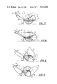
FIG. 1 is a perspective view of one embodiment of dump cart of the invention;
FIG. 2 is a side elevational view of an alternative embodiment of a cam member which is useful in the dump cart of this invention;
FIGS. 3-6 illustrate the dumping action of the cart of this invention; and
FIG. 7 shows an alternative form of actuating means useful in the cart of the invention.
In FIG. 1 there is shown a perspective view of one embodiment of wheeled dump cart 10 of this invention. The cart includes frame member 12, rotatable wheels 14 supporting the frame, box member 16 carried by the frame, handle 18 connected to the frame, cam members 20 pivotably connected to the frame, actuating means 22 operable from the handle for causing the cam member to pivot downwardly, and engagement means 24 (carried by cam 20) which is adapted to engage the box 16 and cause it to pivot forwardly relative to the frame as the cam member pivots downwardly.
The box may be of any size convenient for normal yard and garden use. It may also be made of various materials, e.g., metal, wood, plastic, etc. or a combination of materials. Preferably the front wall 16a is sloped toward the front to facilitate dumping.
The frame member 12 is normally U-shaped and the lower portion of the box rests within the frame. If desired, the entire box may rest above the frame.
Preferably the pivot point for box 16 is located forwardly of the point where the wheels 14 are connected to the frame. In FIG. 1 the box pivots relative to the frame by means of shaft 19 which extends transversely of the frame and passes through the side wall members 16b of the box and the side members of the frame.
The cam is initially caused to pivot forwardly by lever 22a being pushed forwardly against stop 22c so as to cause cable 22b to pull the cam 20 downwardly about its pivot point until teeth 21 engage the ground. The further forward movement of the cart causes further rotation of the cam, with consequent tipping and emptying of the box. After the contents of the box have been dumped, the cart is moved rearwardly by means of handle 18. Spring member 25, connected between the frame 12 and the cam 20, urges the cam 20 back to its normal raised position. Stop 16c on box 16 limits the rearward movement of cam member 20 when finger 24 on cam 20 reaches stop 16c.
Preferably there are two cam members 20, one on each side of the box 16. Each cam pivots on a common axis transverse to the side members of frame member 12.
FIG. 2 illustrates an alternative embodiment of pie-shaped cam member 30. In this embodiment the teeth are similar in shape to gear teeth, as opposed to the spikes shown in the embodiment of FIG. 1. Preferably the teeth extend more than half the way along the curved outer edge of the cam.
In FIGS. 3-6 there are illustrated the various stages the cart of the invention goes through when the contents of the cart are being dumped. In these figures the wheel on the near side has been removed from axle 15 for the purpose of permitting full visual access of the other components of the cart.
The embodiment of the dump cart shown in FIGS. 3-6 is the same as that shown in FIG. 1 except that the cam 20 is shown with serrations 20a on its outer edge instead of spikes. FIGS. 3-6 also show a leg member 32 for supporting the rear portion of the frame member 12 when the cart is at rest.
In FIG. 3 the cam 20 is in its normal raised position. In FIG. 4 lever 22a has been pushed forwardly until it contacts stop member 22c. Lever 22a is pivotably mounted to the handle. The lower end of lever 22a is connected to one end of cable 22b. The opposite end of cable 22b is attached to the lower edge of cam member 20 and accordingly causes cam 20 to pivot about point 19 downwardly so that the lower portion of cam 20 engages the ground. Preferably cam 20 projects slightly beyond the edge of the side wall 16b of box 16.
When the cart is urged forwardly the cam 20 remains firmly set against the ground and therefore rotates relative to frame 12. When finger 24 on cam 20 engages detent 17 on side wall 16b of the box 16, further forward movement of the cart causes box 16 to begin pivoting forwardly about point 19, as illustrated in FIG. 5.
Additional forward movement of the cart causes further rotation of the box 16 about point 19 to cause the contents of the box to be dumped forward of the cart. As the box tips forwardly, stop member 16c prevents the box from totally inverting since it contacts finger 24 on cam 20.
After the contents of the box have been dumped the cart is moved backward slightly, whereupon the spring 25 urges the cam 20 upwardly. Box 16 is accordingly urged back to its normal position supported by frame 12.
In FIG. 7 there is illustrated another embodiment of actuating means which is useful in the present invention. In this embodiment lever 40 is pivotably carried on handle 18. The lower end of lever 40 is connected to rod member 43. The opposite end of rod 43 is connected to arm 45 which is pivotably carried by frame 12.
As the upper end of the lever 40 is urged forwardly against stop 42, the lower end of lever 40 urges rod member 43 rearwardly. This causes arm 45 to pivot rearwardly. One end of rod member 44 is connected to cam 30 while the opposite end of rod 44 passes through a slot in the lower part of arm 45. Oversized end 44a prevents rod 44 from being lost by the slot in arm 45, yet rod 44 may slide rearwardly through the slot as the cam 30 engages the ground and rotates relative to the frame 12 as the box is being emptied.
Other variants are possible without departing from the scope and spirit of the present invention. For example, there may be more than one leg 32 to support the rear portion of frame 12 while the cart is at rest. Also, a wheel may be included on the lower end of leg 32, if desired.
Other variants are also possible.
Claims (7)
1. A wheeled dump cart comprising:
(a) a U-shaped frame member;
(b) two wheels supporting said frame, wherein one said wheel is rotatably mounted on each side of said frame;
(c) a box member carried by said frame and being pivotably connected thereto; said box member including a detent on the outer edge thereof;
(d) a handle member connected to said frame;
(e) a pie-shaped cam member having an inner end and a curved outer edge, wherein said cam member is pivotably connected to said frame and is adapted to pivot from a normally raised position downwardly to a ground-engaging position;
(f) actuating means operable from said handle member for causing said cam member to pivot downwardly;
(g) engagement means comprising a finger, carried by said cam member, which is adapted to engage said detent on said box member and cause said box member to pivot forwardly relative to said frame as said cam member pivots downwardly.
2. A wheeled dump cart in accordance with claim 1, wherein said box member is pivotably connected to said frame at a point forwardly of said wheels, wherein said inner end of said cam member is pivotably connected to said frame at said point.
3. A wheeled dump cart in accordance with claim 2, wherein said frame member further includes a shaft extending transversely from one side of said frame to the other side thereof, wherein said box member and said inner end of said cam member are pivotably connected to said shaft.
4. A wheeled dump cart in accordance with claim 3, wherein, said outer edge of said cam member includes teeth.
5. A wheeled dump cart in accordance with claim 3, wherein said actuating means comprises a lever and a cable, wherein said lever is pivotably carried by said handle, and wherein one end of said cable is connected to said cam member and the opposite end of said cable is connected to said lever.
6. A wheeled dump cart in accordance with claim 3, wherein said actuating means comprises a lever and a linkage comprising first and second rod members and an arm hinged to said frame, wherein said lever is pivotably carried by said handle, wherein one end of said first rod member is connected to said cam member and the opposite end of said first rod is carried by said arm, and wherein one end of said second rod is connected to said arm and the opposite end of said second rod is connected to said lever.
7. A wheeled dump cart in accordance with claim 3, further including spring means adapted to bias said cam member to a normally raised position.
Priority Applications (1)
| Application Number | Priority Date | Filing Date | Title |
|---|---|---|---|
| US06/775,788 US4632461A (en) | 1985-09-13 | 1985-09-13 | Dump cart |
Applications Claiming Priority (1)
| Application Number | Priority Date | Filing Date | Title |
|---|---|---|---|
| US06/775,788 US4632461A (en) | 1985-09-13 | 1985-09-13 | Dump cart |
Publications (1)
| Publication Number | Publication Date |
|---|---|
| US4632461A true US4632461A (en) | 1986-12-30 |
Family
ID=25105505
Family Applications (1)
| Application Number | Title | Priority Date | Filing Date |
|---|---|---|---|
| US06/775,788 Expired - Fee Related US4632461A (en) | 1985-09-13 | 1985-09-13 | Dump cart |
Country Status (1)
| Country | Link |
|---|---|
| US (1) | US4632461A (en) |
Cited By (16)
| Publication number | Priority date | Publication date | Assignee | Title |
|---|---|---|---|---|
| US4859612A (en) * | 1987-10-07 | 1989-08-22 | Hygeia Sciences, Inc. | Metal sol capture immunoassay procedure, kit for use therewith and captured metal containing composite |
| US4861110A (en) * | 1988-06-08 | 1989-08-29 | Rumpke Joseph M | Tilt truck apparatus |
| US4921305A (en) * | 1983-08-30 | 1990-05-01 | Steer Clive Allen | Wheel barrow |
| US5137804A (en) * | 1988-05-10 | 1992-08-11 | E. I. Du Pont De Nemours And Company | Assay device and immunoassay |
| US5215355A (en) * | 1992-10-01 | 1993-06-01 | Joe Klumpjan | Hands-free dumping wagon |
| US5897283A (en) * | 1997-05-21 | 1999-04-27 | Gibson Manufacturing Company | Dumping device |
| US6193319B1 (en) * | 1999-04-01 | 2001-02-27 | Thomas P. Kielinski | Handle-propelled, load-carrying land vehicle |
| US6715775B2 (en) * | 2001-03-15 | 2004-04-06 | Gary V. Abel | Forward dumping two-wheeled barrow |
| US6820940B2 (en) | 2002-02-22 | 2004-11-23 | Edgar Gonzalez | Dump cart sustainer |
| US20080115394A1 (en) * | 2005-09-13 | 2008-05-22 | Downes George R | Wheeled load transfer device |
| US20110133417A1 (en) * | 2008-08-13 | 2011-06-09 | Diversey, Inc. | Adjustable cleaning cart and method |
| US20120146386A1 (en) * | 2009-08-25 | 2012-06-14 | Terry Charles Rowlands | Motorised wheelbarrow |
| USD738062S1 (en) | 2009-11-24 | 2015-09-01 | Diversey, Inc. | Cleaning system trolley |
| US10124820B2 (en) | 2016-03-30 | 2018-11-13 | Vection Ltd. | Method and apparatus for wheelbarrow front end protection |
| CN109249975A (en) * | 2018-11-12 | 2019-01-22 | 王亮 | A kind of architectural engineering ceramic tile transport device |
| US10857926B1 (en) * | 2018-07-20 | 2020-12-08 | Paul Vieira | Front push collapsible pivoting container and frame with wheels |
Citations (13)
| Publication number | Priority date | Publication date | Assignee | Title |
|---|---|---|---|---|
| US396982A (en) * | 1889-01-29 | cable | ||
| US952670A (en) * | 1909-02-27 | 1910-03-22 | Nicholas Fryman | Rack for hay-gatherers. |
| US1549471A (en) * | 1923-12-26 | 1925-08-11 | William B Engler | Automatic dumping mechanism |
| US1804403A (en) * | 1928-03-05 | 1931-05-12 | Francis J Dowling | Loading wheelbarrow |
| US2103866A (en) * | 1936-10-19 | 1937-12-28 | Norris Kathleen | Hand cart |
| US2226492A (en) * | 1937-12-29 | 1940-12-24 | Helmig Carl Friedrich | Barrel rolling and tilting apparatus |
| US2358864A (en) * | 1942-01-12 | 1944-09-26 | Charles H Lockwood | Wheel truck |
| US2533549A (en) * | 1947-01-09 | 1950-12-12 | Bell Aircraft Corp | Power-driven wheelbarrow |
| GB806328A (en) * | 1955-10-31 | 1958-12-23 | Patrick Dunne | Improvements in or relating to loading devices for vehicles |
| US3021625A (en) * | 1957-06-07 | 1962-02-20 | Stasse Roland | Engine powered wheelbarrow |
| US3189387A (en) * | 1959-10-19 | 1965-06-15 | Jr Joe A Nieto | Vehicle motion actuating tilting trailer bed |
| US4023693A (en) * | 1976-02-06 | 1977-05-17 | Priefert Mfg. Co., Inc. | Apparatus for handling a large hay bale |
| US4062591A (en) * | 1974-12-11 | 1977-12-13 | David Harris | Barrow |
-
1985
- 1985-09-13 US US06/775,788 patent/US4632461A/en not_active Expired - Fee Related
Patent Citations (13)
| Publication number | Priority date | Publication date | Assignee | Title |
|---|---|---|---|---|
| US396982A (en) * | 1889-01-29 | cable | ||
| US952670A (en) * | 1909-02-27 | 1910-03-22 | Nicholas Fryman | Rack for hay-gatherers. |
| US1549471A (en) * | 1923-12-26 | 1925-08-11 | William B Engler | Automatic dumping mechanism |
| US1804403A (en) * | 1928-03-05 | 1931-05-12 | Francis J Dowling | Loading wheelbarrow |
| US2103866A (en) * | 1936-10-19 | 1937-12-28 | Norris Kathleen | Hand cart |
| US2226492A (en) * | 1937-12-29 | 1940-12-24 | Helmig Carl Friedrich | Barrel rolling and tilting apparatus |
| US2358864A (en) * | 1942-01-12 | 1944-09-26 | Charles H Lockwood | Wheel truck |
| US2533549A (en) * | 1947-01-09 | 1950-12-12 | Bell Aircraft Corp | Power-driven wheelbarrow |
| GB806328A (en) * | 1955-10-31 | 1958-12-23 | Patrick Dunne | Improvements in or relating to loading devices for vehicles |
| US3021625A (en) * | 1957-06-07 | 1962-02-20 | Stasse Roland | Engine powered wheelbarrow |
| US3189387A (en) * | 1959-10-19 | 1965-06-15 | Jr Joe A Nieto | Vehicle motion actuating tilting trailer bed |
| US4062591A (en) * | 1974-12-11 | 1977-12-13 | David Harris | Barrow |
| US4023693A (en) * | 1976-02-06 | 1977-05-17 | Priefert Mfg. Co., Inc. | Apparatus for handling a large hay bale |
Cited By (20)
| Publication number | Priority date | Publication date | Assignee | Title |
|---|---|---|---|---|
| US4921305A (en) * | 1983-08-30 | 1990-05-01 | Steer Clive Allen | Wheel barrow |
| US4859612A (en) * | 1987-10-07 | 1989-08-22 | Hygeia Sciences, Inc. | Metal sol capture immunoassay procedure, kit for use therewith and captured metal containing composite |
| US5137804A (en) * | 1988-05-10 | 1992-08-11 | E. I. Du Pont De Nemours And Company | Assay device and immunoassay |
| US5391478A (en) * | 1988-05-10 | 1995-02-21 | E. I. Du Pont De Nemours And Company | Assay device and immunoassay |
| US4861110A (en) * | 1988-06-08 | 1989-08-29 | Rumpke Joseph M | Tilt truck apparatus |
| US5215355A (en) * | 1992-10-01 | 1993-06-01 | Joe Klumpjan | Hands-free dumping wagon |
| US5897283A (en) * | 1997-05-21 | 1999-04-27 | Gibson Manufacturing Company | Dumping device |
| US6193319B1 (en) * | 1999-04-01 | 2001-02-27 | Thomas P. Kielinski | Handle-propelled, load-carrying land vehicle |
| US6715775B2 (en) * | 2001-03-15 | 2004-04-06 | Gary V. Abel | Forward dumping two-wheeled barrow |
| US6820940B2 (en) | 2002-02-22 | 2004-11-23 | Edgar Gonzalez | Dump cart sustainer |
| US20080115394A1 (en) * | 2005-09-13 | 2008-05-22 | Downes George R | Wheeled load transfer device |
| US7937859B2 (en) * | 2005-09-13 | 2011-05-10 | Downes George R | Wheeled load transfer device |
| US20110133417A1 (en) * | 2008-08-13 | 2011-06-09 | Diversey, Inc. | Adjustable cleaning cart and method |
| US20120146386A1 (en) * | 2009-08-25 | 2012-06-14 | Terry Charles Rowlands | Motorised wheelbarrow |
| US9108690B2 (en) * | 2009-08-25 | 2015-08-18 | Terry Charles Rowlands | Motorised wheelbarrow |
| USD738062S1 (en) | 2009-11-24 | 2015-09-01 | Diversey, Inc. | Cleaning system trolley |
| US10124820B2 (en) | 2016-03-30 | 2018-11-13 | Vection Ltd. | Method and apparatus for wheelbarrow front end protection |
| USRE48973E1 (en) | 2016-03-30 | 2022-03-15 | Vection Limited | Method and apparatus for wheelbarrow front end protection |
| US10857926B1 (en) * | 2018-07-20 | 2020-12-08 | Paul Vieira | Front push collapsible pivoting container and frame with wheels |
| CN109249975A (en) * | 2018-11-12 | 2019-01-22 | 王亮 | A kind of architectural engineering ceramic tile transport device |
Similar Documents
| Publication | Publication Date | Title |
|---|---|---|
| US4632461A (en) | Dump cart | |
| US5284218A (en) | Motorized cart with front wheel drive | |
| US5088751A (en) | Garden cart | |
| US4922696A (en) | Grass collecting/utility cart for riding lawn mower | |
| US5794305A (en) | Articulation device for a vacuum cleaner | |
| US4921305A (en) | Wheel barrow | |
| US5048206A (en) | Combined snow shoveling device and cart | |
| US4071920A (en) | Sweeper | |
| US7017998B2 (en) | Adaptable transport | |
| US7937859B2 (en) | Wheeled load transfer device | |
| US4179828A (en) | Multi-purpose labor saver hand tool | |
| US4161073A (en) | Snow scoop | |
| US3594932A (en) | Combined snow plow and garden cart | |
| US6050576A (en) | Ground level loading cart | |
| US6446989B1 (en) | Pin drive wheelbarrow | |
| US20020113389A1 (en) | Tipping wheelbarrow | |
| US6715980B2 (en) | Tiltable container | |
| US2965910A (en) | Push cart with detachable sweeper unit | |
| CA1252493A (en) | Dump cart | |
| US6290301B1 (en) | Self-dumping cart | |
| US5067737A (en) | Wheelbarrow having a pair of auxiliary dumping rods | |
| US4372064A (en) | Power lawn mower with dumping receptacle | |
| GB2192595A (en) | Kerb climbing device for a wheeled vehicle | |
| US3160439A (en) | Hand dump truck | |
| US3833262A (en) | Dumping scraper-barrow |
Legal Events
| Date | Code | Title | Description |
|---|---|---|---|
| FPAY | Fee payment |
Year of fee payment: 4 |
|
| FPAY | Fee payment |
Year of fee payment: 8 |
|
| REMI | Maintenance fee reminder mailed | ||
| LAPS | Lapse for failure to pay maintenance fees | ||
| FP | Lapsed due to failure to pay maintenance fee |
Effective date: 19981230 |
|
| STCH | Information on status: patent discontinuation |
Free format text: PATENT EXPIRED DUE TO NONPAYMENT OF MAINTENANCE FEES UNDER 37 CFR 1.362 |