US4608548A - Miniature fuse - Google Patents
Miniature fuse Download PDFInfo
- Publication number
- US4608548A US4608548A US06/688,956 US68895685A US4608548A US 4608548 A US4608548 A US 4608548A US 68895685 A US68895685 A US 68895685A US 4608548 A US4608548 A US 4608548A
- Authority
- US
- United States
- Prior art keywords
- fuse
- base
- cover
- terminals
- insulating
- Prior art date
- Legal status (The legal status is an assumption and is not a legal conclusion. Google has not performed a legal analysis and makes no representation as to the accuracy of the status listed.)
- Expired - Fee Related
Links
Images


Classifications
-
- H—ELECTRICITY
- H01—ELECTRIC ELEMENTS
- H01H—ELECTRIC SWITCHES; RELAYS; SELECTORS; EMERGENCY PROTECTIVE DEVICES
- H01H85/00—Protective devices in which the current flows through a part of fusible material and this current is interrupted by displacement of the fusible material when this current becomes excessive
- H01H85/02—Details
- H01H85/04—Fuses, i.e. expendable parts of the protective device, e.g. cartridges
- H01H85/041—Fuses, i.e. expendable parts of the protective device, e.g. cartridges characterised by the type
- H01H85/0411—Miniature fuses
- H01H85/0415—Miniature fuses cartridge type
- H01H85/0417—Miniature fuses cartridge type with parallel side contacts
-
- H—ELECTRICITY
- H01—ELECTRIC ELEMENTS
- H01H—ELECTRIC SWITCHES; RELAYS; SELECTORS; EMERGENCY PROTECTIVE DEVICES
- H01H69/00—Apparatus or processes for the manufacture of emergency protective devices
- H01H69/02—Manufacture of fuses
- H01H2069/027—Manufacture of fuses using ultrasonic techniques
-
- H—ELECTRICITY
- H01—ELECTRIC ELEMENTS
- H01H—ELECTRIC SWITCHES; RELAYS; SELECTORS; EMERGENCY PROTECTIVE DEVICES
- H01H85/00—Protective devices in which the current flows through a part of fusible material and this current is interrupted by displacement of the fusible material when this current becomes excessive
- H01H85/02—Details
- H01H85/04—Fuses, i.e. expendable parts of the protective device, e.g. cartridges
- H01H85/041—Fuses, i.e. expendable parts of the protective device, e.g. cartridges characterised by the type
- H01H85/0411—Miniature fuses
- H01H2085/0412—Miniature fuses specially adapted for being mounted on a printed circuit board
-
- H—ELECTRICITY
- H01—ELECTRIC ELEMENTS
- H01H—ELECTRIC SWITCHES; RELAYS; SELECTORS; EMERGENCY PROTECTIVE DEVICES
- H01H85/00—Protective devices in which the current flows through a part of fusible material and this current is interrupted by displacement of the fusible material when this current becomes excessive
- H01H85/0078—Security-related arrangements
- H01H85/0082—Security-related arrangements preventing explosion of the cartridge
Definitions
- the invention relates to miniature electrical fuses for use with circuit voltages of at least about 100 rms volts AC. While many aspects of the invention have a broader application, the most important application thereof is in miniature fuses to be mounted on printed circuit boards. At voltages as high as 250 volts the miniature fuses of the invention are generally less than one inch long, and preferably less than one half inch long for most current ratings and no greater than about one quarter inch wide.
- the width of the fuses thus had to be greater than the terminal spacing and the height of the fuse was equal or greater than its width.
- printed circuit fuses capable of withstanding such energies are relatively large, bulky fuses with cylindrical insulating bodies. Also such cylindrical fuses are too bulky for mounting on carrier strips wound on dispensing reels which can be conveniently inserted into automated machinery which automatically insert the fuses into the printed circuit board.
- fuses used on printed circuit boards have fuse terminals which project from opposite axial ends of the body and terminate in parallel confronting terminal ends pluggable into socket openings in the printed circuit board, but these fuses when designed to accommodate the energies involved, have also been undesirably large. Since the general objective in printed circuitry is miniaturization, it is desirable that the fuse itself occupy as little space on the printed circuit board as possible.
- This patent discloses a fuse structure employing a fuse element spanning a cavity defined between D-shaped insulating arc barrier-forming bosses in a cylindrical base portion of the fuse.
- the bosses are slotted to receive the fuse element and have recesses to receive and expose the terminals of the fuses to which the fuse element ends are soldered.
- a rigid cover overlies the base portion of the fuse.
- the fuse design is inadequate to withstand without rupturing the pressures and temperatures present in a 250 volt circuit when made with less than 0.4 inch exposed to arcing terminal separation.
- the circuit plug in terminals are spaced parallel pins, the overall size of such a fuse would be much greater than the terminal spacing.
- the invention deals with, among other things, an arc propagation suppression system which increases the voltage rating of fuses of short overall length, which is useful when desired in printed circuit application.
- a fuse features preferably a rectangular base having conducting terminal members with inner fuse wire attachment contact surfaces located inwardly of the ends of the base.
- the fuse wire preferably extends tautly between these surfaces.
- Each of these terminal members have a first outer end portion projecting axially from a different end of the base, and a second outer end portion folded downward so that the outermost end portions of the terminal members extend in parallel confronting relation, particularly configured for insertion into the terminal-receiving openings of a printed circuit board on which the fuse is rigidly supported.
- the fuse will be described as though the fuse were mounted on top of a printed circuit board generally horizontally disposed.
- the fuse wire extends across a cavity-forming recess in the base and then along insulating surfaces on the opposite sides of the recess base. These surfaces include a pair of upstanding transverse ribs disposed close to the fuse wire terminal attachment points. The insulating surfaces of the ribs are slightly raised above these attachment surfaces of the terminals so as to lightly tense the fuse wire at two points immediately proximate to the attachment surfaces. By this means masses of insulating material (the top faces of the ribs) are in intimate contact with the end portions of the fuse wire in advance of their points of contact with the terminal members.
- each rib is preferably provided with a pair of further upwardly extending insulating rib-like projections disposed on opposite sides of the fuse wire to form at least a three-wall confining shroud further confining and therefor further quenching a propagating arc.
- an insulating cover is provided which is sealable to the base member to provide a spray-resistant seal thereto, said cover being configured with inwardly extending projections configured to engage, or to be in close but spaced relationship to, each rib structure and fuse wire lying thereon to provide a fourth wall for forming complete arc confining shrouds about the fuse wire.
- the cover may be configured also to provide said rib-like projections to provide the same arc-confining action.
- a blowout arc propagating towards the fuse wire attachment points must pass over the support ribs, which are preferably chosen to be of a material which provides a quenching action to an arc propagating in contact therewith.
- Such coplanar arrangements give rise to variable degrees of thermal contact between the fuse wire and the insulating regions, resulting in variations in fuse blowout current values in those cases where the fuse current approaches the nominal blowout value relatively slowly.
- United Kingdom Pat. No. 517,153 shows a low voltage (e.g. 12 volt) automotive fuse, which is not a miniature fuse operating at voltages like 60 to 250 volts, and illustrating the problems overcome by the present invention.
- the fuse disclosed in this patent has complementary housing shells 1, 2 captively sandwiching end terminals 5--5 and the ends of a fuse wire therebetween. Even if this patent were to be considered relevant art to the high voltage fuse of the present invention, there would still be no teaching of offsetting the end terminals from the fuse wire axis or providing the enclosing rib structure described for enclosing at least 3 and preferably all of the sides of the fuse wire ends found desirably in miniature fuses. Also, the pressure of the two halves of the housing upon the fuse wire sandwiched therebetween is possibly damaging to a fragile fuse wire.
- the present invention is also to be contrasted with the arc-confining structures shown in U.S. Pat. No. 3,913,051 to Manker et. al. which discloses a miniature fuse comprising a body of insulating material having a small depression or well formed therein and having a fuse element spanning the well and resting upon metallized support surfaces on the body beyond the well.
- a pair of terminals have inner ends which overlie and are secured by solder joints to the end portions of the fuse elements.
- Shrink tubing tightly envelops this entire assembly to seal the fuse interior, in particular forming a tight confinement about the terminal portions of the fuse wire.
- this sleeve is to localize the traveling arc during burnout to a narrow channel proximate to either surface of the printed circuit board and comprising the end terminals of structure, so as to provide "a significant elongation of the arc and significant increase of the arc voltage at a period of time following arc initiation rather than at the time of arc initiation.”
- the same arc-confinement means as exhibited by the Manker reference is employed, and similarly suffering from possible loss of confinement and explosure rupture of the structure as the arc actually enters the confining region.
- the terminal members exit the ends of the base through a cut-out in the upstanding walls surrounding the periphery of the base at the ends thereof, and the cover is configured with a downwardly extending blade-like extension thereof, having an energy director at the ends, so that the cover may be ultrasonically welded to the base and all points along the peripheral walls thereof, as well as to the upper surface of each terminal member, thereby holding energy transfer to the terminal member at a minimum, while at the same time providing a spray-resistant seal around the entire structure.
- the base of the housing is configured for axial lay-in insertion of a length of fuse wire of arbitrarily long length with respect to the major dimension of the fuse, so that fuse wires may be soldered in place along a continuous string of such base members during manufacture, thereby minimizing handling and positioning of delicate fuse wires.
- the interior annular regions of the upstanding peripheral walls of the base member are provided with an interior annular groove
- the cover is configured with downwardly extending portions of complementary configuration, so that ultrasonic fusion during the sealing of the cover to the base member occurs along a restricted area interface, and so that ultrasonic energy transmitted to the fuse wire during the sealing operation is held to an absolute minimum to minimize wire vibration and possible breakage.
- the fuses disclosed are characterized by ease of manufacture, substantially improved yield in the handling and manipulation of delicate fuse wires when making low amperage fuses, and greater arc-quenching capabilities at high voltages for a given fuse length.
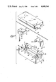
- FIG. 1 is a perspective view of a fuse assembly
- FIG. 2 is an exploded assembly view of the fuse assembly of FIG. 1 showing a base member, two terminal members, a length of fuse wire, and a sealing cap;
- FIG. 3 is a cross-section side view of the fuse assembly of FIG. 1;
- FIG. 4 is a cross section view of the fuse assembly of FIG. 1.
- FIG. 5 is a partially sectioned top view of a partially assembled base assembly as indicated by the offset cut lines in FIG. 3.
- FIGS. 6-9 are various cross-section views of the fuse assembly of FIG. 1 sectioned as indicated in FIG. 3;
- FIGS. 10 and 11 are cross-section views of the fuse holder of FIG. 1, showing the cap immediately before and after placement respectively, and prior to the welding together thereof;
- FIG. 12 is a perspective bottom view of the cover for the fuse of FIG. 1;
- FIG. 13 is a plan view of a modified base member having modified end contacts, showing the fuse wire soldered into position;
- FIG. 14 is a center cross sectional view of the assembled base of FIG. 13 and the cover of FIG. 12, showing the fuse wire captively secured in a modified end terminal having a centering crotch therein;
- FIG. 15 is a cross-section side view of the assembled fuse of FIG. 14.
- FIG. 1 shows an assembled fuse adapted for printed circuit board mounting, the fuse as shown being one embodiment of the subject matter of the invention.
- the fuse 10 consists of a housing including a generally rectangular base 14 having a sealing cover 13 affixed thereto, terminal members 24 exiting axially from the ends and folded generally downward as shown in the figure to present lead portions 26 projecting generally parallel for insertion into a printed circuit board.
- FIG. 2 is an exploded view showing the components of the fuse of FIG. 1.
- FIG. 3 shows the arrangement of internal components after assembly.
- the terminal members 24 are configured with parallel planar contacting portions 25 (see FIG. 2) and downwardly facing retention ends 27 carrying engaging barbs or projections 28 adapted to engagingly fit into base slots 30 (see the partial assembly view shown in FIG. 5), so that by pressing insertion of the ends 27 into the base slots the terminals are retained sufficiently securely that the remainder of the assembly operations may be carried out.
- the inserted terminal members 24 exit the peripheral walls 32 of the base 14 through end openings 36 (FIG. 2).
- a length of fuse wire 18 is then laid over and in contact with the contacting regions 25 of the inserted terminal members 24, the wires being secured in position most preferably by a solder drop 20 (FIG. 5).
- a raised rib 22 integral with the base 14, is disposed to bear against the fuse wire 18, so that the soldered fuse wire after soldering is in tension engagement against this base rib.
- the base rib 22 and as will subsequently be discussed, additional surrounding ribs, serve by their close proximity to or contact with the fuse wire 18 to inhibit the propagation of arcs formed along the fuse wire during blowout, so as to prevent arc propagation into contact with the massive contacting regions 25 of terminal members 24.
- Such a condition is well known in the art to be conducive to catastrophic explosive rupture of the fuse housing, resulting in danger to nearby components, as well as presenting a general fire hazard. In this respect, it will be noted (FIG.
- the cover 13 With the fuse wire 18 soldered in place, the cover 13 is lowered over the base 14, the cover having a downwardly extending ridge 45 adapted to match the interior contours of base walls 32, the insertion thereof terminating by engagement of the upper surfaces 38 of the base walls with a step 47 (FIG. 10) in the ridge.
- a step 47 FIG. 10
- FIGS. 10 and 11 show the initial sequence of cover assembly before welding.
- the width of the step 47 in the ridge 45 is kept deliberately small, thereby also minimizing the total vibration transfer area of the structure.
- vibration transfer precautions are necessary, particularly when dealing with extremely small fuse wires as 0.0003 inches in diameter, in order to prevent resonant wire breakage.
- conical energy directors 16 are disposed in the cover 13 as shown in FIG. 2 and FIG. 12 to press against the planar contacting regions as shown in dotted outlines 16' in FIG. 5. Additionally, a pair of energy director blades 51 having tapered ends 52 are disposed to lie over the end openings 36 and to pressingly engage the region shown by the dotted outlines 51' in FIG. 5.
- the energy director elements 16 and 51 are dimensioned sufficiently short that during the initial engagement of the cover 13 with the base 14 (FIG. 10), they make no contact with the terminals 24. As the cover 13 settles into the base 14 during the ultrasonic welding operation, ultimately the energy directors 16 and 51 come into contact with the terminal members 24 in the regions marked 51' and 16' in FIG. 5, to cause slight local melting and minimal energy transfer to the base 14 and to the fuse wire 18, thereby minimizing the possibility of fuse wire breakage.
- FIGS. 8 and 9 showing cross section views of the engagement of the energy directors 16 and 51 with a terminal member 24.
- fuse elements may be used than the indicated examplary small filamentary fuse wire 18, as for example a fuse element in the form of a ribbon.
- fragility of the fuse element does not pose the severe requirements on vibration during cover welding, and in such a case the cover may be welded until the cover shroud 55 physically contacts the fuse ribbon to terminate further downward movement of the cap.
- the cover 13 and the base 14 are each provided with respective matching half-cavities 41 and 43 between the base ribs 22, thereby providing a substantial gas expansion volume around the fuse wire 18, so as to minimize the explosive effects of the fuse arc.
- a pair of integral cover shrouds 55 are provided on the cover 13, the shroud elements being configured to insertingly fit within the walls 59 disposed on either side of the base rib 22 during cover assembly. This arrangement is best shown in the cross section view of FIG. 7.
- the fuse wire 18 is in pressing engagement with the base rib 22, and is surrounded in close proximity by three complementary interior walls 59-59-55.
- the interior base shroud walls 59 may be placed quite close to each other to provide additional confinement to the propagating arc during blowout, thereby contributing materially to the arc quenching action. It is a general rule in such structures, that the more insulating material is brought into close proximity with the fuse wire, the better the quenching action, and hence the higher the possible voltage rating for a given overall fuse dimension.
- fuse quenching may optionally be secured by placing a small quantity of liquid curable insulating material, such as self-vulcanizing silicone rubber, over the rib 22 immediately prior to cap assembly, by which means a total sealing action about the fuse wire 18 is secured, with no air space between the fuse wire and any of the four surrounding walls.
- liquid curable insulating material such as self-vulcanizing silicone rubber
- the rigid surrounding support provided to such a quenching agent by the four rigid elements 22, 59, 59, and 55 is to be compared with the previously mentioned limitations of the use of a simple resilient or shrinkable sleeve securing the fuse wire in contact with the fuse holder body as discussed in the Summary of Invention with respect to the Manker and Hitchcock patents.
- FIG. 3 An additional blowout protection measure is employed as shown in FIG. 3, wherein another small quantity of silicone rubber is employed as a small pool 40 over the ends of the fuse wire 18 to serve as an additional quenching element in the immediate vicinity of the terminals 24.
- the fuse 10 is uniquely adapted to mass fabriction of fuses of very low current range, in which extremely fine fuse wires 18 must be employed.
- the fuse wire 18 may be dispensed under very light tension from a dispensing spool (not shown) to be lightly flexed over the rib 22 and then soldered to the contacting regions 25 of the terminal members 24.
- the entire assembly may then be moved with the fuse wire attached to both terminals 24 along the general axis defined by the extended fuse wire 18 shown in FIG.
- terminal members 24 may be integrally molded with the base 14 during fabrication of the base, and thus the hold-down energy director 16 on the cap 13 would not be necessary to hold the base terminal in place. It is equally evident that the lead attachment portions 26 of the end terminals 24 could be brought directly out through the bottom of the base member 14, and would not extend through the end passages 36 as shown, for example FIG. 13. In such an arrangement, however, the sealing blades and energy directors 51 and 52 would have to be retained as a sealing feature in order to allow the previously mentioned mass fabrication technique to be employed, because an unobstructed passage of the fuse wire 18 over the contacting terminals 24 and through the end passages 36 is central to the particular mode of mass fabrication described.
- FIGS. 13-15 show an alternative embodiment wherein modified terminals 24', having upstanding ears 76 defining a crotch 74, are either press fitted or integrally molded into a base 14' to extend out the bottom thereof.
- the ears 76 serve to captively center a laid in fuse wire 18 during assembly, the fuse wire being secured into the crotch 74 of each terminal 24' by melting of a solder 78, typically applied in the form of a paste solder cream.
- end passages 36' provided in the base 14' are provided for mass production fuse wire insertion, the cover sealing the end passages 36' by means of a pair of complementary director blades 51 as before.
- the interior shrouding of the fuse wire 18 is unchanged.
- the crotch type terminal 24' is to be preferred for certain types of slow-blow fuse wires involving a ceramic fuse wire filament matrix, to which conventional soldering operations have proven to be difficult.
- a well in the form of a crotch 74 a substantial pool of solder 78, held in place by surface tension, effectively surrounds the entire fuse wire 18 to insure adequate electrical contact thereto.
Abstract
Description
Claims (22)
Priority Applications (1)
| Application Number | Priority Date | Filing Date | Title |
|---|---|---|---|
| US06/688,956 US4608548A (en) | 1985-01-04 | 1985-01-04 | Miniature fuse |
Applications Claiming Priority (1)
| Application Number | Priority Date | Filing Date | Title |
|---|---|---|---|
| US06/688,956 US4608548A (en) | 1985-01-04 | 1985-01-04 | Miniature fuse |
Publications (1)
| Publication Number | Publication Date |
|---|---|
| US4608548A true US4608548A (en) | 1986-08-26 |
Family
ID=24766487
Family Applications (1)
| Application Number | Title | Priority Date | Filing Date |
|---|---|---|---|
| US06/688,956 Expired - Fee Related US4608548A (en) | 1985-01-04 | 1985-01-04 | Miniature fuse |
Country Status (1)
| Country | Link |
|---|---|
| US (1) | US4608548A (en) |
Cited By (52)
| Publication number | Priority date | Publication date | Assignee | Title |
|---|---|---|---|---|
| US4894633A (en) * | 1988-12-12 | 1990-01-16 | American Telephone And Telegraph Company | Fuse Apparatus |
| EP0370572A1 (en) * | 1988-11-21 | 1990-05-30 | Littelfuse B.V. | Fuse |
| US5162773A (en) * | 1990-10-11 | 1992-11-10 | Soc Corporation | High breaking capacity micro-fuse |
| EP0621621A2 (en) * | 1993-04-23 | 1994-10-26 | Gould Electronics Inc. | Current limiting fuses |
| US5363082A (en) * | 1993-10-27 | 1994-11-08 | Rapid Development Services, Inc. | Flip chip microfuse |
| US5606301A (en) * | 1993-10-01 | 1997-02-25 | Soc Corporation | Micro-chip fuse and method of manufacturing the same |
| DE19605252A1 (en) * | 1995-08-30 | 1997-03-06 | Soc Corp | Surface mount micro-miniature fusible link |
| US6275135B1 (en) * | 1998-10-01 | 2001-08-14 | Yazaki Corporation | Large current fuse for automobiles |
| US6452474B1 (en) * | 1999-03-04 | 2002-09-17 | Littelfuse, Inc. | Barrier fuse |
| US6486766B1 (en) * | 2000-03-14 | 2002-11-26 | Littlefuse, Inc. | Housing for double-ended fuse |
| US6566599B2 (en) * | 1999-12-03 | 2003-05-20 | Sumitomo Wiring Systems, Ltd. | Fuse unit and manufacturing method thereof |
| US20030166352A1 (en) * | 2002-03-04 | 2003-09-04 | Seibang Oh | Multi-element fuse array |
| US20030222752A1 (en) * | 2002-05-31 | 2003-12-04 | Yazaki Corporation | Fuse |
| US20040160301A1 (en) * | 2003-02-19 | 2004-08-19 | Nippon Seisen Cable, Ltd. | Miniature fuse |
| US20050190519A1 (en) * | 2003-11-26 | 2005-09-01 | Brown William P. | Vehicle electrical protection device and system employing same |
| US20060055497A1 (en) * | 2004-09-15 | 2006-03-16 | Harris Edwin J | High voltage/high current fuse |
| US20060066436A1 (en) * | 2004-09-24 | 2006-03-30 | Amphenol-Tuchel Electronics Gmbh | Fuse for high-current applications |
| US20060119465A1 (en) * | 2004-12-03 | 2006-06-08 | Dietsch G T | Fuse with expanding solder |
| US20070075822A1 (en) * | 2005-10-03 | 2007-04-05 | Littlefuse, Inc. | Fuse with cavity forming enclosure |
| US20070132539A1 (en) * | 2005-06-02 | 2007-06-14 | Wickmann-Werke Gmbh | Fusible spiral conductor for a fuse component with a plastic seal |
| US20080218304A1 (en) * | 2005-06-20 | 2008-09-11 | Littelfuse, Inc. | Water resistant in-line fuse holder |
| US20080272877A1 (en) * | 2004-06-18 | 2008-11-06 | Alpi Co., Ltd | Fuse Device |
| US20090015365A1 (en) * | 2006-03-16 | 2009-01-15 | Matsushita Electric Industrial Co., Ltd. | Surface-mount current fuse |
| US20090027155A1 (en) * | 2007-07-26 | 2009-01-29 | Hiroo Arikawa | Fuse |
| US20090091218A1 (en) * | 2007-04-04 | 2009-04-09 | Panasonic Corporation | Temperature protection device for brushless dc motor |
| US20100127817A1 (en) * | 2008-11-25 | 2010-05-27 | Banzo Juan I | Fuse assembly and fuse therefor |
| US20100245025A1 (en) * | 2009-03-25 | 2010-09-30 | Littelfuse, Inc. | Solderless surface mount fuse |
| US20100289612A1 (en) * | 2009-05-14 | 2010-11-18 | Hung-Chih Chiu | Current protection device and the method for forming the same |
| US20100328020A1 (en) * | 2009-06-26 | 2010-12-30 | Sidharta Wiryana | Subminiature fuse with surface mount end caps and improved connectivity |
| US20110057761A1 (en) * | 2009-09-04 | 2011-03-10 | Cyntec Co., Ltd. | Protective device |
| US7983024B2 (en) | 2007-04-24 | 2011-07-19 | Littelfuse, Inc. | Fuse card system for automotive circuit protection |
| CN102198863A (en) * | 2010-03-24 | 2011-09-28 | 哈米尔顿森德斯特兰德公司 | Aircraft slat disconnect sensor |
| US20110234237A1 (en) * | 2010-03-24 | 2011-09-29 | Timothy Michael Mayer | Aircraft slat disconnect sensor |
| US20120133478A1 (en) * | 2010-11-30 | 2012-05-31 | Hung-Chih Chiu | Fuse assembly |
| US20140035717A1 (en) * | 2011-04-22 | 2014-02-06 | Yazaki Corporation | Fuse |
| US20140266565A1 (en) * | 2013-03-14 | 2014-09-18 | Littelfuse, Inc. | Laminated electrical fuse |
| US20140300444A1 (en) * | 2013-03-14 | 2014-10-09 | Littelfuse, Inc. | Laminated electrical fuse |
| US20150009007A1 (en) * | 2013-03-14 | 2015-01-08 | Littelfuse, Inc. | Laminated electrical fuse |
| US9117615B2 (en) | 2010-05-17 | 2015-08-25 | Littlefuse, Inc. | Double wound fusible element and associated fuse |
| WO2016118800A1 (en) * | 2015-01-22 | 2016-07-28 | Littelfuse, Inc. | Wire in air split fuse with built-in arc quencher |
| US9460882B2 (en) | 2013-03-14 | 2016-10-04 | Littelfuse, Inc. | Laminated electrical fuse |
| US20170236675A1 (en) * | 2016-02-17 | 2017-08-17 | Littelfuse, Inc. | High current one-piece fuse element and split body |
| CN107093774A (en) * | 2017-04-21 | 2017-08-25 | 江苏银基烯碳能源科技有限公司 | A kind of fuse suite |
| US20190318894A1 (en) * | 2017-11-27 | 2019-10-17 | Conquer Electronics Co., Ltd. | Fuse line fixing structure of fuse |
| US20200006030A1 (en) * | 2017-02-28 | 2020-01-02 | Dexerials Corporation | Fuse device |
| CN111463089A (en) * | 2019-01-21 | 2020-07-28 | 力特保险丝公司 | Fuse and method of forming fuse |
| US20210074502A1 (en) * | 2018-01-10 | 2021-03-11 | Dexerials Corporation | Fuse device |
| US11437212B1 (en) * | 2021-08-06 | 2022-09-06 | Littelfuse, Inc. | Surface mount fuse with solder link and de-wetting substrate |
| WO2022233504A1 (en) * | 2021-05-05 | 2022-11-10 | Siba Fuses Gmbh | Fuse, and method for manufacturing a fuse |
| US11721509B1 (en) * | 2022-04-27 | 2023-08-08 | Conquer Electronics Co., Ltd. | Easy-to-assemble fuse |
| DE102018108020B4 (en) | 2017-04-05 | 2023-11-30 | Littelfuse, Inc. | SURFACE MOUNT FUSE AND METHOD FOR MAKING SAME |
| WO2024079955A1 (en) * | 2022-10-12 | 2024-04-18 | 太平洋精工株式会社 | Fuse |
Citations (1)
| Publication number | Priority date | Publication date | Assignee | Title |
|---|---|---|---|---|
| US4511875A (en) * | 1982-03-19 | 1985-04-16 | S.O.C. Corporation | Micro-fuse assembly |
-
1985
- 1985-01-04 US US06/688,956 patent/US4608548A/en not_active Expired - Fee Related
Patent Citations (1)
| Publication number | Priority date | Publication date | Assignee | Title |
|---|---|---|---|---|
| US4511875A (en) * | 1982-03-19 | 1985-04-16 | S.O.C. Corporation | Micro-fuse assembly |
Cited By (90)
| Publication number | Priority date | Publication date | Assignee | Title |
|---|---|---|---|---|
| EP0370572A1 (en) * | 1988-11-21 | 1990-05-30 | Littelfuse B.V. | Fuse |
| US5130688A (en) * | 1988-11-21 | 1992-07-14 | Littlefuse Tracor B.V. | Fuse |
| US4894633A (en) * | 1988-12-12 | 1990-01-16 | American Telephone And Telegraph Company | Fuse Apparatus |
| US5162773A (en) * | 1990-10-11 | 1992-11-10 | Soc Corporation | High breaking capacity micro-fuse |
| EP0621621A2 (en) * | 1993-04-23 | 1994-10-26 | Gould Electronics Inc. | Current limiting fuses |
| EP0621621A3 (en) * | 1993-04-23 | 1995-11-08 | Gould Electronics Inc | Current limiting fuses. |
| US5606301A (en) * | 1993-10-01 | 1997-02-25 | Soc Corporation | Micro-chip fuse and method of manufacturing the same |
| US5363082A (en) * | 1993-10-27 | 1994-11-08 | Rapid Development Services, Inc. | Flip chip microfuse |
| DE19605252B4 (en) * | 1995-08-30 | 2004-07-15 | Soc Corp. | Surface mount micro-miniature fusible link |
| DE19605252A1 (en) * | 1995-08-30 | 1997-03-06 | Soc Corp | Surface mount micro-miniature fusible link |
| US6275135B1 (en) * | 1998-10-01 | 2001-08-14 | Yazaki Corporation | Large current fuse for automobiles |
| US6452474B1 (en) * | 1999-03-04 | 2002-09-17 | Littelfuse, Inc. | Barrier fuse |
| US6642834B1 (en) * | 1999-03-04 | 2003-11-04 | Littelfuse, Inc. | High voltage automotive use |
| US6566599B2 (en) * | 1999-12-03 | 2003-05-20 | Sumitomo Wiring Systems, Ltd. | Fuse unit and manufacturing method thereof |
| US6580032B2 (en) | 1999-12-03 | 2003-06-17 | Sumitomo Wiring Systems, Ltd. | Fuse unit and manufacturing method therefor |
| US6624356B2 (en) * | 1999-12-03 | 2003-09-23 | Sumitomo Wiring Systems, Ltd. | Fuse unit and manufacturing method therefor |
| US6486766B1 (en) * | 2000-03-14 | 2002-11-26 | Littlefuse, Inc. | Housing for double-ended fuse |
| US6878004B2 (en) | 2002-03-04 | 2005-04-12 | Littelfuse, Inc. | Multi-element fuse array |
| US20030166352A1 (en) * | 2002-03-04 | 2003-09-04 | Seibang Oh | Multi-element fuse array |
| US6828896B2 (en) * | 2002-05-31 | 2004-12-07 | Yazaki Corporation | Fuse |
| US20030222752A1 (en) * | 2002-05-31 | 2003-12-04 | Yazaki Corporation | Fuse |
| US20040160301A1 (en) * | 2003-02-19 | 2004-08-19 | Nippon Seisen Cable, Ltd. | Miniature fuse |
| US6930585B2 (en) * | 2003-02-19 | 2005-08-16 | Nippon Seisen Cable, Ltd. | Miniature fuse |
| US7233474B2 (en) | 2003-11-26 | 2007-06-19 | Littelfuse, Inc. | Vehicle electrical protection device and system employing same |
| US20050190519A1 (en) * | 2003-11-26 | 2005-09-01 | Brown William P. | Vehicle electrical protection device and system employing same |
| US20080272877A1 (en) * | 2004-06-18 | 2008-11-06 | Alpi Co., Ltd | Fuse Device |
| US20060055497A1 (en) * | 2004-09-15 | 2006-03-16 | Harris Edwin J | High voltage/high current fuse |
| US7659804B2 (en) | 2004-09-15 | 2010-02-09 | Littelfuse, Inc. | High voltage/high current fuse |
| US20100194519A1 (en) * | 2004-09-15 | 2010-08-05 | Littelfuse, Inc. | High voltage/high current fuse |
| US20060066436A1 (en) * | 2004-09-24 | 2006-03-30 | Amphenol-Tuchel Electronics Gmbh | Fuse for high-current applications |
| US20060119465A1 (en) * | 2004-12-03 | 2006-06-08 | Dietsch G T | Fuse with expanding solder |
| US20070132539A1 (en) * | 2005-06-02 | 2007-06-14 | Wickmann-Werke Gmbh | Fusible spiral conductor for a fuse component with a plastic seal |
| US8009010B2 (en) * | 2005-06-20 | 2011-08-30 | Littlefuse, Inc. | Water resistant in-line fuse holder |
| US20080218304A1 (en) * | 2005-06-20 | 2008-09-11 | Littelfuse, Inc. | Water resistant in-line fuse holder |
| US20100164678A1 (en) * | 2005-06-20 | 2010-07-01 | Littelfuse, Inc. | Water resistant in-line fuse holder |
| US20090102595A1 (en) * | 2005-10-03 | 2009-04-23 | Littlefuse, Inc. | Fuse with cavity forming enclosure |
| US20070075822A1 (en) * | 2005-10-03 | 2007-04-05 | Littlefuse, Inc. | Fuse with cavity forming enclosure |
| WO2007041529A3 (en) * | 2005-10-03 | 2007-07-19 | Littelfuse Inc | Fuse with cavity forming enclosure |
| WO2007041529A2 (en) * | 2005-10-03 | 2007-04-12 | Littelfuse, Inc. | Fuse with cavity forming enclosure |
| US20090015365A1 (en) * | 2006-03-16 | 2009-01-15 | Matsushita Electric Industrial Co., Ltd. | Surface-mount current fuse |
| US8368502B2 (en) * | 2006-03-16 | 2013-02-05 | Panasonic Corporation | Surface-mount current fuse |
| US20090091218A1 (en) * | 2007-04-04 | 2009-04-09 | Panasonic Corporation | Temperature protection device for brushless dc motor |
| US8188627B2 (en) * | 2007-04-04 | 2012-05-29 | Panasonic Corporation | Temperature protection device for brushless DC motor |
| US7983024B2 (en) | 2007-04-24 | 2011-07-19 | Littelfuse, Inc. | Fuse card system for automotive circuit protection |
| US20090027155A1 (en) * | 2007-07-26 | 2009-01-29 | Hiroo Arikawa | Fuse |
| US20100127817A1 (en) * | 2008-11-25 | 2010-05-27 | Banzo Juan I | Fuse assembly and fuse therefor |
| US20100245025A1 (en) * | 2009-03-25 | 2010-09-30 | Littelfuse, Inc. | Solderless surface mount fuse |
| US8937524B2 (en) * | 2009-03-25 | 2015-01-20 | Littelfuse, Inc. | Solderless surface mount fuse |
| US8081057B2 (en) * | 2009-05-14 | 2011-12-20 | Hung-Chih Chiu | Current protection device and the method for forming the same |
| US20100289612A1 (en) * | 2009-05-14 | 2010-11-18 | Hung-Chih Chiu | Current protection device and the method for forming the same |
| US20100328020A1 (en) * | 2009-06-26 | 2010-12-30 | Sidharta Wiryana | Subminiature fuse with surface mount end caps and improved connectivity |
| US8203420B2 (en) * | 2009-06-26 | 2012-06-19 | Cooper Technologies Company | Subminiature fuse with surface mount end caps and improved connectivity |
| US20110057761A1 (en) * | 2009-09-04 | 2011-03-10 | Cyntec Co., Ltd. | Protective device |
| US9336978B2 (en) | 2009-09-04 | 2016-05-10 | Cyntec Co., Ltd. | Protective device |
| US9129769B2 (en) * | 2009-09-04 | 2015-09-08 | Cyntec Co., Ltd. | Protective device |
| US20110234237A1 (en) * | 2010-03-24 | 2011-09-29 | Timothy Michael Mayer | Aircraft slat disconnect sensor |
| CN102198863A (en) * | 2010-03-24 | 2011-09-28 | 哈米尔顿森德斯特兰德公司 | Aircraft slat disconnect sensor |
| US8516898B2 (en) * | 2010-03-24 | 2013-08-27 | Hamilton Sundstrand Corporation | Aircraft slat disconnect sensor |
| CN102198863B (en) * | 2010-03-24 | 2015-08-12 | 哈米尔顿森德斯特兰德公司 | Aircraft slat throws off sensor |
| US9117615B2 (en) | 2010-05-17 | 2015-08-25 | Littlefuse, Inc. | Double wound fusible element and associated fuse |
| US8629749B2 (en) * | 2010-11-30 | 2014-01-14 | Hung-Chih Chiu | Fuse assembly |
| US20120133478A1 (en) * | 2010-11-30 | 2012-05-31 | Hung-Chih Chiu | Fuse assembly |
| US9685294B2 (en) * | 2011-04-22 | 2017-06-20 | Yazaki Corporation | Fuse |
| US20140035717A1 (en) * | 2011-04-22 | 2014-02-06 | Yazaki Corporation | Fuse |
| US20150009007A1 (en) * | 2013-03-14 | 2015-01-08 | Littelfuse, Inc. | Laminated electrical fuse |
| US20140300444A1 (en) * | 2013-03-14 | 2014-10-09 | Littelfuse, Inc. | Laminated electrical fuse |
| US20140266565A1 (en) * | 2013-03-14 | 2014-09-18 | Littelfuse, Inc. | Laminated electrical fuse |
| US9460882B2 (en) | 2013-03-14 | 2016-10-04 | Littelfuse, Inc. | Laminated electrical fuse |
| KR20170084315A (en) * | 2015-01-22 | 2017-07-19 | 리텔퓨즈 인코퍼레이티드 | Wire in air split fuse with built-in arc quencher |
| CN107112171A (en) * | 2015-01-22 | 2017-08-29 | 力特保险丝公司 | Fuse in air separation fuse provided with built-in extinguisher |
| WO2016118800A1 (en) * | 2015-01-22 | 2016-07-28 | Littelfuse, Inc. | Wire in air split fuse with built-in arc quencher |
| US9824842B2 (en) | 2015-01-22 | 2017-11-21 | Littelfuse, Inc. | Wire in air split fuse with built-in arc quencher |
| US20190088436A1 (en) * | 2016-02-17 | 2019-03-21 | Littelfuse, Inc. | High current one-piece fuse element and split body |
| US10141150B2 (en) * | 2016-02-17 | 2018-11-27 | Littelfuse, Inc. | High current one-piece fuse element and split body |
| TWI654638B (en) | 2016-02-17 | 2019-03-21 | 美商李特爾佛斯公司 | High current one-piece fuse element and split body |
| US20170236675A1 (en) * | 2016-02-17 | 2017-08-17 | Littelfuse, Inc. | High current one-piece fuse element and split body |
| US10854412B2 (en) * | 2016-02-17 | 2020-12-01 | Littelfuse, Inc. | High current one-piece fuse element and split body |
| US20200006030A1 (en) * | 2017-02-28 | 2020-01-02 | Dexerials Corporation | Fuse device |
| US11145480B2 (en) * | 2017-02-28 | 2021-10-12 | Dexerials Corporation | Fuse device |
| DE102018108020B4 (en) | 2017-04-05 | 2023-11-30 | Littelfuse, Inc. | SURFACE MOUNT FUSE AND METHOD FOR MAKING SAME |
| CN107093774A (en) * | 2017-04-21 | 2017-08-25 | 江苏银基烯碳能源科技有限公司 | A kind of fuse suite |
| US20190318894A1 (en) * | 2017-11-27 | 2019-10-17 | Conquer Electronics Co., Ltd. | Fuse line fixing structure of fuse |
| US10854413B2 (en) * | 2017-11-27 | 2020-12-01 | Conquer Electronics Co., Ltd. | Fuse line fixing structure of fuse |
| US20210074502A1 (en) * | 2018-01-10 | 2021-03-11 | Dexerials Corporation | Fuse device |
| CN111463089A (en) * | 2019-01-21 | 2020-07-28 | 力特保险丝公司 | Fuse and method of forming fuse |
| US11521818B2 (en) * | 2019-01-21 | 2022-12-06 | Littelfuse, Inc. | Fuses and methods of forming fuses |
| WO2022233504A1 (en) * | 2021-05-05 | 2022-11-10 | Siba Fuses Gmbh | Fuse, and method for manufacturing a fuse |
| US11437212B1 (en) * | 2021-08-06 | 2022-09-06 | Littelfuse, Inc. | Surface mount fuse with solder link and de-wetting substrate |
| US11721509B1 (en) * | 2022-04-27 | 2023-08-08 | Conquer Electronics Co., Ltd. | Easy-to-assemble fuse |
| WO2024079955A1 (en) * | 2022-10-12 | 2024-04-18 | 太平洋精工株式会社 | Fuse |
Similar Documents
| Publication | Publication Date | Title |
|---|---|---|
| US4608548A (en) | Miniature fuse | |
| US4563666A (en) | Miniature fuse | |
| US4612529A (en) | Subminiature fuse | |
| US4749980A (en) | Sub-miniature fuse | |
| US4511875A (en) | Micro-fuse assembly | |
| JP6537619B2 (en) | Wires in air split fuses with built-in arc quencher | |
| KR100392915B1 (en) | Electric lamp | |
| US4656453A (en) | Cartridge fuse with two arc-quenching end plugs | |
| US3198914A (en) | Thermally operated electrical disconnect device | |
| JPH0720828Y2 (en) | Ultra-small current fuse | |
| US5252942A (en) | Fuse links and dual element fuse | |
| US6642833B2 (en) | High-voltage current-limiting fuse | |
| US5162773A (en) | High breaking capacity micro-fuse | |
| US2889424A (en) | Relay | |
| JPH0318010A (en) | Capacitor with fuse | |
| KR910003658B1 (en) | Fuse for high-voltage circuit | |
| JP2005158352A (en) | Electric wire with fuse | |
| US4926543A (en) | Method of making a sub-miniature fuse | |
| USRE33137E (en) | Subminiature fuse | |
| GB2062981A (en) | Miniature electric fuse | |
| JPH0541486Y2 (en) | ||
| US6369504B1 (en) | Low pressure mercury vapor discharge lamp | |
| US5122774A (en) | Sub-miniature electrical component, particularly a fuse | |
| US3611239A (en) | High-voltage fuse having inner core and outer shell fuse links | |
| US3713063A (en) | Method of and means for making a current limiting fuse |
Legal Events
| Date | Code | Title | Description |
|---|---|---|---|
| AS | Assignment |
Owner name: LITTLEFUSE ,INC., A CORP OF TEXAS Free format text: ASSIGNMENT OF ASSIGNORS INTEREST.;ASSIGNOR:BORZONI, JOHN;REEL/FRAME:004368/0443 Effective date: 19841227 |
|
| AS | Assignment |
Owner name: TORONTO-DOMINION BANK, THE, AS AGENT Free format text: SECURITY INTEREST;ASSIGNOR:TRACOR, INC.;REEL/FRAME:004810/0209 Effective date: 19871216 |
|
| AS | Assignment |
Owner name: BANK OF AMERICA NATIONAL TRUST AND SAVINGS ASSOCIA Free format text: SECURITY INTEREST;ASSIGNOR:TRACOR, INC.;REEL/FRAME:005217/0247 Effective date: 19880801 Owner name: BANK OF AMERICA AS AGENT Free format text: SECURITY INTEREST;ASSIGNOR:TORONTO-DOMINION BANK, THE;REEL/FRAME:005197/0122 Effective date: 19880801 Owner name: TORONTO-DOMINION BANK, THE Free format text: SECURITY INTEREST;ASSIGNORS:TRACOR, INC.;LITTLEFUSE, INC.;TRACOR AEROSPACE, INC.;AND OTHERS;REEL/FRAME:005234/0127 Effective date: 19880801 Owner name: BANK OF AMERICA NATIONAL TRUST AND SAVINGS ASSOCIA Free format text: SECURITY INTEREST;ASSIGNORS:TORONTO-DOMINION BANK;TRACOR, INC.;REEL/FRAME:005224/0276 Effective date: 19880801 Owner name: BANK OF AMERICA NATIONAL TRUST AND SAVINGS ASSOCIA Free format text: SECURITY INTEREST;ASSIGNOR:TRACOR INC.;REEL/FRAME:005217/0224 Effective date: 19880801 |
|
| AS | Assignment |
Owner name: BANK OF AMERICA NATIONAL TRUST AND SAVINGS ASSOCIA Free format text: SECURITY INTEREST;ASSIGNOR:TRACOR HOLDINGS, INC., TRACOR, INC., AND OTHERS INDICATED ON SCHEDULE SA;REEL/FRAME:005317/0726 Effective date: 19891030 |
|
| REMI | Maintenance fee reminder mailed | ||
| LAPS | Lapse for failure to pay maintenance fees | ||
| STCH | Information on status: patent discontinuation |
Free format text: PATENT EXPIRED DUE TO NONPAYMENT OF MAINTENANCE FEES UNDER 37 CFR 1.362 |
|
| FP | Lapsed due to failure to pay maintenance fee |
Effective date: 19900826 |
|
| AS | Assignment |
Owner name: TRACOR, INC. Free format text: RELEASED BY SECURED PARTY;ASSIGNOR:BANK OF AMERICA NATIONAL TRUST AND SAVINGS ASSOCIATION AS COLLATERAL AGENT;REEL/FRAME:005957/0542 Effective date: 19911227 Owner name: TRACOR, INC. Free format text: RELEASED BY SECURED PARTY;ASSIGNOR:BANK OF AMERICA NATIONAL TRUST AND SAVINGS ASSOCIATION;REEL/FRAME:005953/0942 Effective date: 19911227 Owner name: TRACOR, INC. Free format text: RELEASED BY SECURED PARTY;ASSIGNOR:BANK OF AMERICA NATIONAL TRUST AND SAVINGS ASSOCIATION AS COLLATERAL AGENT;REEL/FRAME:005957/0562 Effective date: 19911220 |