US4606706A - Internal compliant seal for compressor - Google Patents
Internal compliant seal for compressor Download PDFInfo
- Publication number
- US4606706A US4606706A US06/789,891 US78989185A US4606706A US 4606706 A US4606706 A US 4606706A US 78989185 A US78989185 A US 78989185A US 4606706 A US4606706 A US 4606706A
- Authority
- US
- United States
- Prior art keywords
- seal
- port
- tubular member
- chamber
- flange
- Prior art date
- Legal status (The legal status is an assumption and is not a legal conclusion. Google has not performed a legal analysis and makes no representation as to the accuracy of the status listed.)
- Expired - Lifetime
Links
Images
Classifications
-
- F—MECHANICAL ENGINEERING; LIGHTING; HEATING; WEAPONS; BLASTING
- F16—ENGINEERING ELEMENTS AND UNITS; GENERAL MEASURES FOR PRODUCING AND MAINTAINING EFFECTIVE FUNCTIONING OF MACHINES OR INSTALLATIONS; THERMAL INSULATION IN GENERAL
- F16J—PISTONS; CYLINDERS; SEALINGS
- F16J15/00—Sealings
- F16J15/02—Sealings between relatively-stationary surfaces
- F16J15/021—Sealings between relatively-stationary surfaces with elastic packing
- F16J15/022—Sealings between relatively-stationary surfaces with elastic packing characterised by structure or material
- F16J15/024—Sealings between relatively-stationary surfaces with elastic packing characterised by structure or material the packing being locally weakened in order to increase elasticity
- F16J15/025—Sealings between relatively-stationary surfaces with elastic packing characterised by structure or material the packing being locally weakened in order to increase elasticity and with at least one flexible lip
-
- F—MECHANICAL ENGINEERING; LIGHTING; HEATING; WEAPONS; BLASTING
- F04—POSITIVE - DISPLACEMENT MACHINES FOR LIQUIDS; PUMPS FOR LIQUIDS OR ELASTIC FLUIDS
- F04B—POSITIVE-DISPLACEMENT MACHINES FOR LIQUIDS; PUMPS
- F04B39/00—Component parts, details, or accessories, of pumps or pumping systems specially adapted for elastic fluids, not otherwise provided for in, or of interest apart from, groups F04B25/00 - F04B37/00
- F04B39/12—Casings; Cylinders; Cylinder heads; Fluid connections
- F04B39/123—Fluid connections
-
- F—MECHANICAL ENGINEERING; LIGHTING; HEATING; WEAPONS; BLASTING
- F04—POSITIVE - DISPLACEMENT MACHINES FOR LIQUIDS; PUMPS FOR LIQUIDS OR ELASTIC FLUIDS
- F04D—NON-POSITIVE-DISPLACEMENT PUMPS
- F04D29/00—Details, component parts, or accessories
- F04D29/08—Sealings
- F04D29/083—Sealings especially adapted for elastic fluid pumps
-
- Y—GENERAL TAGGING OF NEW TECHNOLOGICAL DEVELOPMENTS; GENERAL TAGGING OF CROSS-SECTIONAL TECHNOLOGIES SPANNING OVER SEVERAL SECTIONS OF THE IPC; TECHNICAL SUBJECTS COVERED BY FORMER USPC CROSS-REFERENCE ART COLLECTIONS [XRACs] AND DIGESTS
- Y10—TECHNICAL SUBJECTS COVERED BY FORMER USPC
- Y10S—TECHNICAL SUBJECTS COVERED BY FORMER USPC CROSS-REFERENCE ART COLLECTIONS [XRACs] AND DIGESTS
- Y10S417/00—Pumps
- Y10S417/902—Hermetically sealed motor pump unit
Definitions
- This invention generally pertains to an internal compressor seal or connecting line and specifically to a seal that extends between a port in a compressor shell and another port in the wall of an internal chamber.
- Assembly of a typical hermetic compressor often requires that components fit inside the hermetic shell with very small tolerances for radial, axial, and angular position. This is particularly troublesome when attaching an internal suction line between a port in the shell and a port on an internal chamber attached to the compressor or motor body. Manufacturing tolerance and human error can cause substantial variation in the initial position of the compressor/motor assembly relative to the port in the shell.
- Another object is to provide an internal seal that is sufficiently compliant to accommodate movement of the compressor/motor assembly during operation of the compressor.
- a still further object is to provide a seal that is relatively easy to install during the assembly of the compressor.
- Yet a still further object is to provide a relatively low cost internal compliant seal.
- the subject invention is a seal used in a compressor having an outer shell and an internal chamber spaced apart from the inner surface of the outer shell.
- the seal extends between a first port disposed in the outer shell and a second port disposed in the internal chamber. It comprises a tubular member sized to closely fit through the first port in sliding engagement therewith.
- the other end of the tubular member includes a cone-shaped flange that sealingly contacts the outer surface of the chamber around the second port.
- the flange has a plurality of spaced apart radial slots which permit it to flatten out under compression when attachment of a suction line to the suction port forces the seal inward. Fluid flow between the first and second ports is thereby substantially confined within the seal.
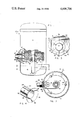
- FIG. 1 shows a cross-sectional view of the seal, visible in a cutaway view of the hermetic shell of a compressor.
- FIG. 2 is a cross-sectional view of the compressor and seal taken along section line 2--2 of FIG. 1.
- FIG. 3 is a cross-sectional view of a portion of the compressor taken along section line 3--3 of FIG. 1.
- FIG. 4 is a perspective view of the seal comprising the subject invention.
- FIG. 1 A compressor system generally denoted by reference numeral 10 is shown in FIG. 1.
- Compressor system 10 is a rotary compressor, housed in a hermetic shell 11.
- the actual compressor portion of system 10 is not shown in FIG. 1 since details regarding the compressor need not be disclosed to understand the form and function of the subject invention; however, in an actual application of the preferred embodiment of the invention, a scroll compressor is used.
- a sliding vane compressor or other rotary compressor would be equally suitable.
- Compressor system 10 is driven by an internal electric motor 12 which includes a stator 13 and rotor 14.
- a drive shaft 15 passes through rotor 14, and its lower end extends into a reservoir of oil 16.
- Centrifugal oil pump 17 is disposed at the lower distal end of drive shaft 15 and is operative to cause oil to flow upward through an internal bore 18 within the drive shaft, as it rotates. This oil is used to lubricate surfaces subject to friction within the compressor and bearings such as the lower drive shaft main bearing 19.
- Drive shaft main bearing 19 is supported by a cast framework member 20.
- Framework 20 is connected to stator 13 with three threaded bolts 21, disposed at spaced intervals around its periphery and completely underlies and encloses the lower end of motor 12.
- suction port 25 Included on the suction port is a threaded fitting 26 used to secure a suction line 27 by means of a mating threaded nut 28.
- the end of suction line 27 is drawn up against a square section teflon seal as the threaded nut 28 is tightened, thereby forming a hermetic seal.
- the end of suction line 27 also abuts against the end of seal 30, forcing it to slide inwardly within suction port 25.
- Seal 30 includes a cylindrical tubular portion 31 having a diameter slightly smaller than the diameter of suction port 25.
- a conical flange 32 is formed on the end of seal 30 that extends inside of hermetic shell 11.
- Flange 32 includes three spaced apart radially aligned slots 33 which extend radially inward from its outer circumference almost to the tubular body portion. Slots 33 serve to increase the flexibility of conical flange 32, permitting it to flatten under compression.
- seal 30 is injection molded of a relatively stiff but flexible, plastic material. The elastic characteristics of this material and provision of slots 33 contribute to the flexural compliancy of conical flange 32.
- ribs 34 are formed on the outer surface of the tubular portion 31 at spaced apart intervals. These ribs improve the ease with which seal 30 is slidingly fit within suction port 25. Any small variations in the diameter of suction port 25 is compensated for by flexure of the wall of the tubular member 31 between each of the ribs 34, thereby substantially increasing its tolerance to such dimensional variations.
- seal 30 is inserted within suction port 25 from inside shell 11 prior to the installation of motor 12, and pushed-in until flange 32 abuts against the inside of hermetic shell 11. Once seal 30 is in place, motor 12 (and attached compressor--not shown) can be positioned and fastened in place within hermetic shell 11 without any interference in fit from the seal.
- the outer wall of chamber 40 includes a port 41.
- flange 32 Prior to the installation of suction line 27, flange 32 does not contact the outer surface of framework 20, since, as explained above, when seal 30 is initially installed, it is pushed all the way into suction port 25 from the inside of hermetic shell 11. After suction line 27 is connected, seal 30 is forced inward toward the outer surface of chamber 40, and conical flange 32 contacts that surface and flattens slightly around the periphery of port 41 under the force of compression provided by the connected suction line.
- the outer surface of framework 20 is die cast to form a flat surface 42 around port 41 against which flange 32 abuts.
- the flat surface 42 improves the quality of the seal formed by conical flange 32 as it flattens under compression.
- the spacing between the inner surface of hermetic shell 11 around suction port 25 and surface 42 around port 41 is not critical, because conical flange 32 can flex (by flattening) up to one-quarter of an inch after it initially contacts surface 42.
- seal 30 also permits a substantial tolerance in axial dimension and in angular displacement of port 41 relative to suction port 25, i.e., the relative displacement between the centers of port 41 and suction port 25.
- the diameter of the outer periphery of conical flange 32 is greater than the diameter of port 41. Since flange 32 is cone shaped and the periphery of the flange initially contacts flat surface 42, the center of suction port 25 (and of seal 30) need not be perfectly aligned with the center of port 41 to provide an adequate seal.
- the fluid surrounding chamber 40 within hermetic shell 11 is substantially at compressor suction pressure and that pressure is less than 1 psi lower than the pressure of suction fluid entering suction port 25. Since there is a very small differential pressure between the fluid in chamber 40 and the fluid surrounding chamber 40 enclosed within hermetic shell 11, a very small percentage of the suction gas flowing through seal 30 leaks out through the imperfect seal caused by slots 33. The relatively small leakage that does occur, is of little significance since any fluid that leaks into the volume enclosed by shell 11 still enters the compression cycle. It is only necessary that a substantial portion of the suction fluid passing through seal 30 enter chamber 40.
- chamber 40 is generally "L" shaped in cross section, and rectangular in plan view.
- An access plug 43 is installed in a hole formed in framework 20 during assembly of compressor 10, as is a filter screen 44.
- Suction gas entering suction port 25 flows through internal seal 30 and into chamber 40 so that it can be channeled through motor 12 for cooling purposes prior to entering the compression cycle.
- the suction gas flowing out of chamber 40 passes through filter screen 44 and up through the rotor/stator annulus 45 to cool the windings on stator 13. Any oil carried with the suction gas into the area of the motor 12 flows back into reservoir 16 through an oil drain orifice 46 disposed within the bottom of framework member 20, on the side opposite chamber 40.
- Internal seal 30 provides an inexpensive means for directing suction gas from a suction port 25 to an internal chamber 40 without the use of a bulky and expensive internal connecting line.
- seal 30 improves the ease with which compressor 10 is assembled during manufacture, allows substantial tolerance in the dimensions between the ports which it seals and between which it conveys suction fluid, and is sufficiently compliant to maintain an adequate seal even during vibration of the motor 12 relative to hermetic shell 11 during operation of compressor system 10. It will be appreciated, that although internal seal 30 is a relatively simple component, it provides substantial advantages over the known prior art.
Landscapes
- Engineering & Computer Science (AREA)
- General Engineering & Computer Science (AREA)
- Mechanical Engineering (AREA)
- Compressor (AREA)
- Applications Or Details Of Rotary Compressors (AREA)
Abstract
Description
Claims (14)
Priority Applications (7)
| Application Number | Priority Date | Filing Date | Title |
|---|---|---|---|
| US06/789,891 US4606706A (en) | 1985-10-21 | 1985-10-21 | Internal compliant seal for compressor |
| CA000515406A CA1263420A (en) | 1985-10-21 | 1986-08-06 | Internal compliant seal for compressor |
| GB08620103A GB2181795B (en) | 1985-10-21 | 1986-08-19 | Compressor having internal compliant seal |
| DE19863633487 DE3633487A1 (en) | 1985-10-21 | 1986-10-02 | COMPRESSOR SYSTEM |
| JP61245602A JPH0668275B2 (en) | 1985-10-21 | 1986-10-17 | Internal follower seal for compressor |
| FR8614553A FR2588924B1 (en) | 1985-10-21 | 1986-10-20 | FLEXIBLE INNER SEAL FOR COMPRESSOR |
| HK947/92A HK94792A (en) | 1985-10-21 | 1992-11-26 | Compressor having internal compliant seal |
Applications Claiming Priority (1)
| Application Number | Priority Date | Filing Date | Title |
|---|---|---|---|
| US06/789,891 US4606706A (en) | 1985-10-21 | 1985-10-21 | Internal compliant seal for compressor |
Publications (1)
| Publication Number | Publication Date |
|---|---|
| US4606706A true US4606706A (en) | 1986-08-19 |
Family
ID=25149002
Family Applications (1)
| Application Number | Title | Priority Date | Filing Date |
|---|---|---|---|
| US06/789,891 Expired - Lifetime US4606706A (en) | 1985-10-21 | 1985-10-21 | Internal compliant seal for compressor |
Country Status (7)
| Country | Link |
|---|---|
| US (1) | US4606706A (en) |
| JP (1) | JPH0668275B2 (en) |
| CA (1) | CA1263420A (en) |
| DE (1) | DE3633487A1 (en) |
| FR (1) | FR2588924B1 (en) |
| GB (1) | GB2181795B (en) |
| HK (1) | HK94792A (en) |
Cited By (15)
| Publication number | Priority date | Publication date | Assignee | Title |
|---|---|---|---|---|
| US4793775A (en) * | 1984-10-13 | 1988-12-27 | Aspera S.R.L. | Hermetic motor-compressor unit for refrigeration circuits |
| US4844705A (en) * | 1988-01-25 | 1989-07-04 | Tecumseh Products Company | Suction line adaptor and filter for a hermetic compressor |
| EP0386320A1 (en) * | 1989-03-08 | 1990-09-12 | Tecumseh Products Company | Suction line connector for hermetic compressor |
| US5015155A (en) * | 1990-03-26 | 1991-05-14 | Copeland Corporation | Motor cover assembly and method |
| DE9409461U1 (en) * | 1994-06-10 | 1995-08-03 | Hansa Technik Gmbh | Graphic device with compressed air powered graphic tool and a compressor |
| US5562427A (en) * | 1992-10-23 | 1996-10-08 | Matsushita Refrigeration Company | Filter arrangement for a refrigerant compressor |
| US5607291A (en) * | 1993-12-21 | 1997-03-04 | Matsushita Electric Industrial Co., Ltd. | Closed compressor |
| US6162033A (en) * | 1998-07-23 | 2000-12-19 | Carrier Corporation | Compressor economizer tube assembly |
| US6254354B1 (en) * | 1998-09-02 | 2001-07-03 | American Standard Inc. | Enhanced suction gas management in a refrigeration compressor |
| US6379130B1 (en) | 2000-06-09 | 2002-04-30 | Tecumseh Products Company | Motor cover retention |
| US20080219863A1 (en) * | 2007-03-06 | 2008-09-11 | Lg Electronics Inc. | Connector for hermetic compressor and suction device of working fluid using the same |
| WO2013142419A1 (en) | 2012-03-23 | 2013-09-26 | Bitzer Kühlmaschinenbau Gmbh | Suction duct with heat-staked screen |
| US20130266459A1 (en) * | 2012-04-09 | 2013-10-10 | Panasonic Corporation | Sealed compressor |
| KR20160095818A (en) * | 2015-02-04 | 2016-08-12 | 엘지전자 주식회사 | Reciprocating compressor |
| USD943551S1 (en) * | 2019-05-23 | 2022-02-15 | Tymphany Acoustic Technology (Huizhou) Co., Ltd. | Diaphragm for loudspeaker |
Families Citing this family (2)
| Publication number | Priority date | Publication date | Assignee | Title |
|---|---|---|---|---|
| DE4411191C2 (en) * | 1994-03-30 | 1997-05-15 | Danfoss Compressors Gmbh | Refrigerant compressor arrangement |
| DE19923427A1 (en) | 1999-05-21 | 2000-11-23 | Lohmann Therapie Syst Lts | Device for improved delivery of active agents to skin, useful e.g. for administering opiates, contains agent that increases local skin temperature or blood flow |
Citations (14)
| Publication number | Priority date | Publication date | Assignee | Title |
|---|---|---|---|---|
| US739082A (en) * | 1901-11-29 | 1903-09-15 | Irad W Hills | Pump. |
| US934983A (en) * | 1908-09-03 | 1909-09-21 | Mueller Mfg Co H | Pipe connection. |
| US1755104A (en) * | 1927-10-03 | 1930-04-15 | Deierlein Edward | Coupling |
| US2153773A (en) * | 1935-10-10 | 1939-04-11 | Edison Calatroni | Compressor unit for refrigeration and other applications |
| CA780239A (en) * | 1968-03-12 | L. Nielsen Axel | Pump and tank coupling means | |
| US3840257A (en) * | 1972-04-24 | 1974-10-08 | Locking Devices Corp | Sealed connector |
| US4086032A (en) * | 1976-08-23 | 1978-04-25 | Mitsubishi Jukogyo Kabushiki Kaisha | Sealed type motor-compressor |
| US4088350A (en) * | 1974-07-05 | 1978-05-09 | The Lee Company | Plastic tubing connector |
| US4240774A (en) * | 1979-02-15 | 1980-12-23 | General Electric Company | Hermetically sealed compressor suction tube and method of assembly |
| US4252346A (en) * | 1977-12-19 | 1981-02-24 | Sundholm Goeran V | Connection for transition from a cutting ring joint or similar to a flange joint |
| JPS5756694A (en) * | 1981-07-29 | 1982-04-05 | Toshiba Corp | Rotary compressor |
| US4496293A (en) * | 1981-12-28 | 1985-01-29 | Mitsubishi Denki Kabushiki Kaisha | Compressor of the scroll type |
| US4538835A (en) * | 1981-12-07 | 1985-09-03 | Sundholm Goeran | Connection for joining a pipe having a flared end to a fixed connection piece, such as a pump |
| US4545742A (en) * | 1982-09-30 | 1985-10-08 | Dunham-Bush, Inc. | Vertical axis hermetic helical screw rotary compressor with discharge gas oil mist eliminator and dual transfer tube manifold for supplying liquid refrigerant and refrigerant vapor to the compression area |
Family Cites Families (7)
| Publication number | Priority date | Publication date | Assignee | Title |
|---|---|---|---|---|
| US3115352A (en) * | 1960-07-20 | 1963-12-24 | Gen Electric | Alignment compensating coupling |
| US3902629A (en) * | 1974-07-05 | 1975-09-02 | Gen Electric | Compressor tube connector seal |
| DE2650937C3 (en) * | 1976-11-08 | 1981-12-10 | Danfoss A/S, 6430 Nordborg | Refrigeration machine with a motor compressor that is resiliently held in a capsule |
| US4382749A (en) * | 1980-11-14 | 1983-05-10 | The Trane Company | Reciprocating compressor with integral unloader valve |
| DE3213476C1 (en) * | 1982-04-10 | 1983-06-01 | Danfoss A/S, 6430 Nordborg | Refrigeration machine with encapsulated motor compressor |
| DD237083A3 (en) * | 1984-04-16 | 1986-07-02 | Dkk Scharfenstein Veb | SUCTION GAS IN THE HERMETIC COILANT COMPRESSOR |
| IT1179810B (en) * | 1984-10-31 | 1987-09-16 | Aspera Spa | HERMETIC MOTOR-COMPRESSOR GROUP FOR REFRIGERANT CIRCUITS |
-
1985
- 1985-10-21 US US06/789,891 patent/US4606706A/en not_active Expired - Lifetime
-
1986
- 1986-08-06 CA CA000515406A patent/CA1263420A/en not_active Expired
- 1986-08-19 GB GB08620103A patent/GB2181795B/en not_active Expired
- 1986-10-02 DE DE19863633487 patent/DE3633487A1/en active Granted
- 1986-10-17 JP JP61245602A patent/JPH0668275B2/en not_active Expired - Lifetime
- 1986-10-20 FR FR8614553A patent/FR2588924B1/en not_active Expired
-
1992
- 1992-11-26 HK HK947/92A patent/HK94792A/en not_active IP Right Cessation
Patent Citations (14)
| Publication number | Priority date | Publication date | Assignee | Title |
|---|---|---|---|---|
| CA780239A (en) * | 1968-03-12 | L. Nielsen Axel | Pump and tank coupling means | |
| US739082A (en) * | 1901-11-29 | 1903-09-15 | Irad W Hills | Pump. |
| US934983A (en) * | 1908-09-03 | 1909-09-21 | Mueller Mfg Co H | Pipe connection. |
| US1755104A (en) * | 1927-10-03 | 1930-04-15 | Deierlein Edward | Coupling |
| US2153773A (en) * | 1935-10-10 | 1939-04-11 | Edison Calatroni | Compressor unit for refrigeration and other applications |
| US3840257A (en) * | 1972-04-24 | 1974-10-08 | Locking Devices Corp | Sealed connector |
| US4088350A (en) * | 1974-07-05 | 1978-05-09 | The Lee Company | Plastic tubing connector |
| US4086032A (en) * | 1976-08-23 | 1978-04-25 | Mitsubishi Jukogyo Kabushiki Kaisha | Sealed type motor-compressor |
| US4252346A (en) * | 1977-12-19 | 1981-02-24 | Sundholm Goeran V | Connection for transition from a cutting ring joint or similar to a flange joint |
| US4240774A (en) * | 1979-02-15 | 1980-12-23 | General Electric Company | Hermetically sealed compressor suction tube and method of assembly |
| JPS5756694A (en) * | 1981-07-29 | 1982-04-05 | Toshiba Corp | Rotary compressor |
| US4538835A (en) * | 1981-12-07 | 1985-09-03 | Sundholm Goeran | Connection for joining a pipe having a flared end to a fixed connection piece, such as a pump |
| US4496293A (en) * | 1981-12-28 | 1985-01-29 | Mitsubishi Denki Kabushiki Kaisha | Compressor of the scroll type |
| US4545742A (en) * | 1982-09-30 | 1985-10-08 | Dunham-Bush, Inc. | Vertical axis hermetic helical screw rotary compressor with discharge gas oil mist eliminator and dual transfer tube manifold for supplying liquid refrigerant and refrigerant vapor to the compression area |
Cited By (19)
| Publication number | Priority date | Publication date | Assignee | Title |
|---|---|---|---|---|
| US4793775A (en) * | 1984-10-13 | 1988-12-27 | Aspera S.R.L. | Hermetic motor-compressor unit for refrigeration circuits |
| US4844705A (en) * | 1988-01-25 | 1989-07-04 | Tecumseh Products Company | Suction line adaptor and filter for a hermetic compressor |
| EP0386320A1 (en) * | 1989-03-08 | 1990-09-12 | Tecumseh Products Company | Suction line connector for hermetic compressor |
| US5015155A (en) * | 1990-03-26 | 1991-05-14 | Copeland Corporation | Motor cover assembly and method |
| US5170555A (en) * | 1990-03-26 | 1992-12-15 | Copeland Corporation | Method of assembling a refrigeration compressor |
| US5562427A (en) * | 1992-10-23 | 1996-10-08 | Matsushita Refrigeration Company | Filter arrangement for a refrigerant compressor |
| US5607291A (en) * | 1993-12-21 | 1997-03-04 | Matsushita Electric Industrial Co., Ltd. | Closed compressor |
| DE9409461U1 (en) * | 1994-06-10 | 1995-08-03 | Hansa Technik Gmbh | Graphic device with compressed air powered graphic tool and a compressor |
| US6162033A (en) * | 1998-07-23 | 2000-12-19 | Carrier Corporation | Compressor economizer tube assembly |
| US6254354B1 (en) * | 1998-09-02 | 2001-07-03 | American Standard Inc. | Enhanced suction gas management in a refrigeration compressor |
| US6379130B1 (en) | 2000-06-09 | 2002-04-30 | Tecumseh Products Company | Motor cover retention |
| US6454549B2 (en) | 2000-06-09 | 2002-09-24 | Tecumseh Products Company | Motor cover retention |
| US20080219863A1 (en) * | 2007-03-06 | 2008-09-11 | Lg Electronics Inc. | Connector for hermetic compressor and suction device of working fluid using the same |
| WO2013142419A1 (en) | 2012-03-23 | 2013-09-26 | Bitzer Kühlmaschinenbau Gmbh | Suction duct with heat-staked screen |
| EP2836721A4 (en) * | 2012-03-23 | 2016-01-27 | Bitzer Kuehlmaschinenbau Gmbh | Suction duct with heat-staked screen |
| US9441631B2 (en) | 2012-03-23 | 2016-09-13 | Bitzer Kuehlmaschinenbau Gmbh | Suction duct with heat-staked screen |
| US20130266459A1 (en) * | 2012-04-09 | 2013-10-10 | Panasonic Corporation | Sealed compressor |
| KR20160095818A (en) * | 2015-02-04 | 2016-08-12 | 엘지전자 주식회사 | Reciprocating compressor |
| USD943551S1 (en) * | 2019-05-23 | 2022-02-15 | Tymphany Acoustic Technology (Huizhou) Co., Ltd. | Diaphragm for loudspeaker |
Also Published As
| Publication number | Publication date |
|---|---|
| GB8620103D0 (en) | 1986-10-01 |
| JPH0668275B2 (en) | 1994-08-31 |
| FR2588924B1 (en) | 1989-08-18 |
| JPS6299683A (en) | 1987-05-09 |
| HK94792A (en) | 1992-12-04 |
| CA1263420A (en) | 1989-11-28 |
| DE3633487A1 (en) | 1987-04-23 |
| GB2181795A (en) | 1987-04-29 |
| FR2588924A1 (en) | 1987-04-24 |
| GB2181795B (en) | 1988-10-19 |
| DE3633487C2 (en) | 1990-03-01 |
Similar Documents
| Publication | Publication Date | Title |
|---|---|---|
| US4606706A (en) | Internal compliant seal for compressor | |
| RU1771517C (en) | Rotary compressor | |
| RU2005125705A (en) | MOISTURIZING ROTARY CIRCULATION PUMP | |
| US4969804A (en) | Suction line connector for hermetic compressor | |
| US4015633A (en) | Assembly for sealing and pressure equalization of a submersible housing | |
| US7108489B2 (en) | Terminal block assembly for a hermetic compressor | |
| US4560329A (en) | Strainer device for rotary compressor | |
| RU2010108256A (en) | UNITED SEALING HEAD AND PUMP INLET ASSEMBLY FOR ELECTRIC SUBMERSIBLE PUMP | |
| US10781805B2 (en) | Small air compressor | |
| US5411383A (en) | Rotor and flexible drive shaft assembly | |
| CA2464216C (en) | Rotary compressor having two-piece separator plate | |
| CN209671276U (en) | Its water pump of a kind of pump head structure of water pump and application | |
| US2404635A (en) | Sealing means for driving motors of submersible pumps | |
| US5152672A (en) | Rotary pump with pressure switch | |
| US4277223A (en) | Case construction for multi-stage pump | |
| JPH0435634B2 (en) | ||
| JP2587712Y2 (en) | Pintle fixing structure of radial plunger pump | |
| RU2208708C2 (en) | Oil-well centrifugal electric pump | |
| US6746218B2 (en) | Compact electrohydraulic motor pump unit | |
| US20080019849A1 (en) | Pumping device | |
| CN212615341U (en) | Inner gearing cycloid gear pump | |
| CN210738804U (en) | Anti-lock screw pump capable of reducing bending deformation of screw | |
| US20230407774A1 (en) | Oil filter arrangement for filtering oil of a vehicle | |
| CN219974835U (en) | Refrigerant pump with compact structure | |
| JP3336721B2 (en) | Rotary compressor |
Legal Events
| Date | Code | Title | Description |
|---|---|---|---|
| AS | Assignment |
Owner name: AMERICAN STANDARD INC., NEW YORK, NEW YORK, A CORP Free format text: ASSIGNMENT OF ASSIGNORS INTEREST.;ASSIGNOR:UTTER, ROBERT E.;REEL/FRAME:004471/0630 Effective date: 19851017 |
|
| STCF | Information on status: patent grant |
Free format text: PATENTED CASE |
|
| AS | Assignment |
Owner name: BANKERS TRUST COMPANY Free format text: SECURITY INTEREST;ASSIGNOR:AMERICAN STANDARD INC., A DE. CORP.,;REEL/FRAME:004905/0035 Effective date: 19880624 Owner name: BANKERS TRUST COMPANY, 4 ALBANY STREET, 9TH FLOOR, Free format text: SECURITY INTEREST;ASSIGNOR:TRANE AIR CONDITIONING COMPANY, A DE CORP.;REEL/FRAME:004905/0213 Effective date: 19880624 Owner name: BANKERS TRUST COMPANY, NEW YORK Free format text: SECURITY INTEREST;ASSIGNOR:TRANE AIR CONDITIONING COMPANY, A DE CORP.;REEL/FRAME:004905/0213 Effective date: 19880624 |
|
| FPAY | Fee payment |
Year of fee payment: 4 |
|
| FEPP | Fee payment procedure |
Free format text: PAYOR NUMBER ASSIGNED (ORIGINAL EVENT CODE: ASPN); ENTITY STATUS OF PATENT OWNER: LARGE ENTITY |
|
| AS | Assignment |
Owner name: CHEMICAL BANK, AS COLLATERAL AGENT, NEW YORK Free format text: ASSIGNMENT OF SECURITY INTEREST;ASSIGNOR:BANKERS TRUST COMPANY, AS COLLATERAL TRUSTEE;REEL/FRAME:006565/0753 Effective date: 19930601 Owner name: CHEMICAL BANK, AS COLLATERAL AGENT, NEW YORK Free format text: ASSIGNMENT OF ASSIGNORS INTEREST;ASSIGNOR:AMERICAN STANDARD INC.;REEL/FRAME:006566/0170 Effective date: 19930601 |
|
| FPAY | Fee payment |
Year of fee payment: 8 |
|
| FPAY | Fee payment |
Year of fee payment: 12 |
|
| AS | Assignment |
Owner name: AMERICAN STANDARD, INC., NEW JERSEY Free format text: RELEASE OF SECURITY INTEREST (RE-RECORD TO CORRECT DUPLICATES SUBMITTED BY CUSTOMER. THE NEW SCHEDULE CHANGES THE TOTAL NUMBER OF PROPERTY NUMBERS INVOLVED FROM 1133 TO 794. THIS RELEASE OF SECURITY INTEREST WAS PREVIOUSLY RECORDED AT REEL 8869, FRAME 0001.);ASSIGNOR:CHASE MANHATTAN BANK, THE (FORMERLY KNOWN AS CHEMICAL BANK);REEL/FRAME:009123/0300 Effective date: 19970801 |
|
| AS | Assignment |
Owner name: AMERICAN STANDARD, INC., NEW JERSEY Free format text: RELEASE OF SECURITY INTEREST;ASSIGNOR:CHASE MANHATTAN BANK, THE (FORMERLY KNOWN AS CHEMICAL BANK);REEL/FRAME:008869/0001 Effective date: 19970801 |
|
| AS | Assignment |
Owner name: AMERICAN STANDARD INTERNATIONAL INC., NEW YORK Free format text: NOTICE OF ASSIGNMENT;ASSIGNOR:AMERICAN STANDARD INC., A CORPORATION OF DELAWARE;REEL/FRAME:011474/0650 Effective date: 20010104 |