US4585981A - Device for driving motor-operated closure parts - Google Patents
Device for driving motor-operated closure parts Download PDFInfo
- Publication number
- US4585981A US4585981A US06/649,293 US64929384A US4585981A US 4585981 A US4585981 A US 4585981A US 64929384 A US64929384 A US 64929384A US 4585981 A US4585981 A US 4585981A
- Authority
- US
- United States
- Prior art keywords
- signal
- closure part
- movement
- transmitting means
- speed
- Prior art date
- Legal status (The legal status is an assumption and is not a legal conclusion. Google has not performed a legal analysis and makes no representation as to the accuracy of the status listed.)
- Expired - Lifetime
Links
Images


Classifications
-
- B—PERFORMING OPERATIONS; TRANSPORTING
- B60—VEHICLES IN GENERAL
- B60J—WINDOWS, WINDSCREENS, NON-FIXED ROOFS, DOORS, OR SIMILAR DEVICES FOR VEHICLES; REMOVABLE EXTERNAL PROTECTIVE COVERINGS SPECIALLY ADAPTED FOR VEHICLES
- B60J7/00—Non-fixed roofs; Roofs with movable panels, e.g. rotary sunroofs
- B60J7/02—Non-fixed roofs; Roofs with movable panels, e.g. rotary sunroofs of sliding type, e.g. comprising guide shoes
- B60J7/04—Non-fixed roofs; Roofs with movable panels, e.g. rotary sunroofs of sliding type, e.g. comprising guide shoes with rigid plate-like element or elements, e.g. open roofs with harmonica-type folding rigid panels
- B60J7/057—Driving or actuating arrangements e.g. manually operated levers or knobs
- B60J7/0573—Driving or actuating arrangements e.g. manually operated levers or knobs power driven arrangements, e.g. electrical
-
- E—FIXED CONSTRUCTIONS
- E05—LOCKS; KEYS; WINDOW OR DOOR FITTINGS; SAFES
- E05F—DEVICES FOR MOVING WINGS INTO OPEN OR CLOSED POSITION; CHECKS FOR WINGS; WING FITTINGS NOT OTHERWISE PROVIDED FOR, CONCERNED WITH THE FUNCTIONING OF THE WING
- E05F15/00—Power-operated mechanisms for wings
- E05F15/40—Safety devices, e.g. detection of obstructions or end positions
- E05F15/41—Detection by monitoring transmitted force or torque; Safety couplings with activation dependent upon torque or force, e.g. slip couplings
-
- H—ELECTRICITY
- H02—GENERATION; CONVERSION OR DISTRIBUTION OF ELECTRIC POWER
- H02H—EMERGENCY PROTECTIVE CIRCUIT ARRANGEMENTS
- H02H7/00—Emergency protective circuit arrangements specially adapted for specific types of electric machines or apparatus or for sectionalised protection of cable or line systems, and effecting automatic switching in the event of an undesired change from normal working conditions
- H02H7/08—Emergency protective circuit arrangements specially adapted for specific types of electric machines or apparatus or for sectionalised protection of cable or line systems, and effecting automatic switching in the event of an undesired change from normal working conditions for dynamo-electric motors
- H02H7/085—Emergency protective circuit arrangements specially adapted for specific types of electric machines or apparatus or for sectionalised protection of cable or line systems, and effecting automatic switching in the event of an undesired change from normal working conditions for dynamo-electric motors against excessive load
- H02H7/0851—Emergency protective circuit arrangements specially adapted for specific types of electric machines or apparatus or for sectionalised protection of cable or line systems, and effecting automatic switching in the event of an undesired change from normal working conditions for dynamo-electric motors against excessive load for motors actuating a movable member between two end positions, e.g. detecting an end position or obstruction by overload signal
-
- E—FIXED CONSTRUCTIONS
- E05—LOCKS; KEYS; WINDOW OR DOOR FITTINGS; SAFES
- E05Y—INDEXING SCHEME RELATING TO HINGES OR OTHER SUSPENSION DEVICES FOR DOORS, WINDOWS OR WINGS AND DEVICES FOR MOVING WINGS INTO OPEN OR CLOSED POSITION, CHECKS FOR WINGS AND WING FITTINGS NOT OTHERWISE PROVIDED FOR, CONCERNED WITH THE FUNCTIONING OF THE WING
- E05Y2900/00—Application of doors, windows, wings or fittings thereof
- E05Y2900/50—Application of doors, windows, wings or fittings thereof for vehicles
- E05Y2900/53—Application of doors, windows, wings or fittings thereof for vehicles characterised by the type of wing
- E05Y2900/542—Roof panels
-
- E—FIXED CONSTRUCTIONS
- E05—LOCKS; KEYS; WINDOW OR DOOR FITTINGS; SAFES
- E05Y—INDEXING SCHEME RELATING TO HINGES OR OTHER SUSPENSION DEVICES FOR DOORS, WINDOWS OR WINGS AND DEVICES FOR MOVING WINGS INTO OPEN OR CLOSED POSITION, CHECKS FOR WINGS AND WING FITTINGS NOT OTHERWISE PROVIDED FOR, CONCERNED WITH THE FUNCTIONING OF THE WING
- E05Y2900/00—Application of doors, windows, wings or fittings thereof
- E05Y2900/50—Application of doors, windows, wings or fittings thereof for vehicles
- E05Y2900/53—Application of doors, windows, wings or fittings thereof for vehicles characterised by the type of wing
- E05Y2900/55—Windows
-
- H—ELECTRICITY
- H02—GENERATION; CONVERSION OR DISTRIBUTION OF ELECTRIC POWER
- H02H—EMERGENCY PROTECTIVE CIRCUIT ARRANGEMENTS
- H02H7/00—Emergency protective circuit arrangements specially adapted for specific types of electric machines or apparatus or for sectionalised protection of cable or line systems, and effecting automatic switching in the event of an undesired change from normal working conditions
- H02H7/08—Emergency protective circuit arrangements specially adapted for specific types of electric machines or apparatus or for sectionalised protection of cable or line systems, and effecting automatic switching in the event of an undesired change from normal working conditions for dynamo-electric motors
- H02H7/085—Emergency protective circuit arrangements specially adapted for specific types of electric machines or apparatus or for sectionalised protection of cable or line systems, and effecting automatic switching in the event of an undesired change from normal working conditions for dynamo-electric motors against excessive load
- H02H7/0854—Emergency protective circuit arrangements specially adapted for specific types of electric machines or apparatus or for sectionalised protection of cable or line systems, and effecting automatic switching in the event of an undesired change from normal working conditions for dynamo-electric motors against excessive load responsive to rate of change of current, couple or speed, e.g. anti-kickback protection
Definitions
- This invention relates to a device for driving motor-operated closure parts, especially on motor vehicles, having a protective system for interrupting the closing movement when an object is situated in the opening so as to be squeezed by the closing parts.
- the invention therefore, has a primary objective of creating a device that ensures increased safety and can be constructed with relatively simple means.
- a speed transmitting means which detects the adjusting speed of the closure part in at least one range of the movement path of the closure part that is critical with respect to the squeezing problem and by means of an evaluating stage responding to the speed signal and/or its rate of change, for producing an obstruction signal that activates the protection system.
- the invention is based on recognition of the fact that motor-driven closure parts, such as sliding roofs, motor vehicle windows and doors, apart from the initial acceleration and the final braking, are driven at an essentially constant speed.
- motor-driven closure parts such as sliding roofs, motor vehicle windows and doors, apart from the initial acceleration and the final braking, are driven at an essentially constant speed.
- the speed of a closing part will suddenly decrease when the closure part encounters an object.
- a speed signal that is proportional to the closing speed therefore, represents a reliable indicator of the danger that an obstruction has been encountered.
- an actual-value position transmitting means is provided that detects the actual position of the closure part, and a differentiating stage is connected to said actual-value position transmitting means for forming the speed signal.
- a speed signal can be obtained simply and reliably.
- the speed transmitting means is expediently provided with a differentiating stage for forming an acceleration signal that corresponds to the acceleration or deceleration of the closure part.
- the position signal and the signals derived from it are not influenced by disturbances, such as the ambient temperature, the condition of the driving mechanism and the motor current.
- the evaluating stage may advantageously also be acted upon by a driving current or a driving voltage signal coming from a transmitting means detecting the current or the driving voltage of the driving motor.
- Closure parts such as a sliding panel and windows or doors of motor vehicles, as a rule, when attaining their closed position, are pressed against a sealing means or similar means which decrease the closing speed, without the continued existence of a danger that such occurred due to an object having been encountered.
- a further aspect of the invention lies in the response sensitivity of the protection system being changed as a functional of the actual position of the closing part.
- the arrangement may, for example, be made in such a way that the protection system is deactivated in at least one predetermined range of the path of movement of the closing part.
- the evaluating stage expediently, has a logic circuit for recognizing a closing movement.
- the evaluating stage preferably has a logic circuit for differentiating between the tilt-out lifting and sliding ranges.
- the evaluating phase is advantageously provided with circuit components for suppressing insignificant signal fluctuations.
- these may be window comparators.
- the drive advantageously, in a known manner (U.S. patent application Ser. No. 530,714) is part of a control circuit provided with a desired-value position transmitting means which compares the position of the closing part selected at the desired-value position transmitting means with its actual position and adjusts the position of the closing part until the deviation has become zero.
- the arrangement can be designed so that the drive is stopped in response to an obstruction signal; however, a preferred design is to reverse the drive in response to the obstruction signal, i.e., automatically change the drive operation from a closing movement to an opening movement.
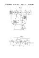
- FIG. 1 is a block diagram of a driving device designed according to the invention for a motor-driven lifting/sliding roof;
- FIG. 2 is a diagram of the differentiating stages for deriving a speed signal and an acceleration signal from a position signal;
- FIG. 3 is a diagram of the evaluating circuit provided in the arrangement according to FIG. 1;
- FIG. 4 is a diagram of a circuit for adjusting the response sensitivity of the protection circuit.
- FIG. 5 is a diagram of a circuit for deactivating the protection circuit in a predetermined range.
- a sliding/lifting roof panel 10 is displaceable by a driving motor 11 via a drive 12, for example, in the form of pressure-resistant thread cables, said thread cables engaging with a pinion driven by the motor 11.
- the motor 11 is controlled by a control device 13 that receives a desired-value position signal U s from a desired-value position transmitting means 14.
- the actual position X of the movable roof panel 10 is detected by an actual-value position transmitting means 15 which produces a corresponding actual-value position signal U i which, in the control device 13, is compared with the desired-value position value U s .
- the actual-value position signal U i is directed to a first differentiating stage 16 which, by differentiating this signal, forms a speed signal U v .
- a second differentiating stage 17 is connected to the differentiating stage 16.
- the second differentiating stage 17 differentiates the speed signal U v to derive an acceleration signal U b .
- the actual-value position signal, U i , the speed signal, U v , and the acceleration signal, U b are directed to an evaluating stage 18 which, as a function of the presence of indicated combinations of the input signals, generates an obstruction signal U k .
- the obstruction signal, U k is directed to the control device 13 which causes a reversal of the rotating direction of the driving motor 11. So that the evaluating stage 18 can differentiate between the lifting and the sliding range of the roof panel 10, a signal U n is applied to another input of the evaluating stage 18, said signal U n corresponding to the closed or neutral position of the roof panel 10.
- the differentiating stage 16 has an operational amplifier 20, the non-inverting input of which is grounded, while a resistor 21 leads back from the output to the inverting input of the operational amplifier.
- a series connection consisting of a resistor 22 and a condenser 23 is connected to the inverting input of the operational amplifier 20.
- the position signal U i is applied to the input side of the resistor 22.
- This position signal U i is differentiated into the speed signal U v at the output of the operational amplifier 20.
- the output of the operational amplifier 20, via a series connection consisting of a resistor 24 and a condenser 25, is connected with the inverting input of an operational amplifier 26 of the second differentiating stage 17.
- a resistor 27 is disposed between the output and the inverting input of the operational amplifier 26.
- the non-inverting input of the amplifier 26 is grounded. In this way, the speed signal U v is changed into the acceleration signal U b by differentiating.
- the evaluating circuit 18 has a group of operational amplifiers 30, 31, 32, 33 and 34.
- a voltage divider consisting of resistors 35, 36 and 37 is connected in series to the operational amplifiers 30, 31.
- a voltage divider with the resistors 38, 39, 40 is located in front of the operational resistors 32, 33.
- the speed signal U v is applied to the non-inverting input of the operational amplifier 30 and the inverting input of the operational amplifier 31.
- the inverting input of the operational amplifier 30 is connected to the connecting point of the resistors 35, 36, while the non-inverting input of the operational amplifier 31 is connected to the connecting point of the resistors 36, 37.
- the amplifier 30, 31 and the voltage divider 35, 36, 37 together form a window comparator in that, at the output of the operational amplifier 30, a positive signal (logic level: “high”) appears when the speed signal U v is larger than a first predetermined threshold value U gr1 .
- a positive signal (logic level: "high”) appears at the output of the operational amplifier 31 when the speed signal U v is smaller than a second predetermined threshold value U gr2 .
- the logic signal level "low” will appear at both operational amplifier outputs.
- the acceleration signal U b goes to the non-inverting input of the amplifier 32 and the inverting input of the amplifier 33.
- the inverting input of the amplifier 32 is connected to the connecting point of the resistors 38, 39, while the non-inverting input of the amplifier 33 is connected to the connecting point of the resistors 39, 40.
- the amplifiers 32, 33 and the voltage divider 38, 39, 40 together form a window comparator in that a positive signal (logic level: "high") appears at the output of the operational amplifier 32, when the acceleration signal U b is larger than a predetermined threshold value U gr3 .
- a positive signal (logic level: "high”) appears at the output of the operational amplifier 33 when the acceleration signal U b is smaller than another predetermined threshold value U gr4 .
- the logic signal level "low” appears at both operational amplifier outputs.
- the outputs of the amplifiers 30, 31 are connected with an input of an AND-circuit 42 and an AND-circuit 43, respectively.
- the output of the amplifier 32 is connected to a second input of the AND-circuit 42, while the output of the amplifier 33 is connected with a second input of the AND-circuit 43.
- the signals U n and U i are applied, respectively, to the non-inverting and the inverting inputs of the operational amplifier 34.
- a signal U p formed by a comparison of signals U n and U i , appears at the output of said operational amplifier 34 for differentiation between the lifting and the sliding range of the roof 10.
- the output of the amplifier 34 is connected to a third input of the AND-circuit 42, and via an inverter 44, is connected with a third input of the AND-circuit 43.
- an evaluating stage as shown in FIG. 4 can be connected in series with either or both of the inputs U v and U b of the circuit arrangement shown in FIG. 3. An evaluation of the velocity signal U v or the acceleration signal U b as a function of the position signal U i is obtained by means of this evaluation stage.
- U i and U v and/or U b depends upon the specific roof design and is simulated by functional networks that are in conformity with the purpose of the apparatus.
- a control voltage U st f(U i ) which is generated in that process, goes through a resistance 49 to a light emitting diode 50 of an optocoupler 51, whose output stage 52 forms a part of a voltage divider with a divider resistance 53.
- the signal U v or U b is applied to the voltage divider 52, 53.
- the evaluating signal U vA or U bA which is then delivered to the operational amplifiers 30, 31 or 32, 33 of FIG. 3, appears at the output 54 of the voltage divider 52, 53.
- the protective circuit may be deactivated in at least one predetermined range of the path of movement of roof panel, especially, the closed position (zero position), since no danger of obstruction exists.
- the operational amplifier 34 and the inverter 44 of the circuit arrangement of FIG. 3 can be replaced by the structural group represented in FIG. 5.
- the circuit arrangement of FIG. 5 has the function of deactivating the protective circuit in a range corresponding to U n ⁇ U.
- the signal U n + ⁇ U is formed by way of an adder 55 and an inverter 56, and is then compared with the position signal U i in a comparator 57.
- U p 1 holds, if U n + ⁇ U is ⁇ U i .
- the signal U n - ⁇ U is formed by an adder 58 and an inverter 59 and is compared with the position signal U i in a comparator 60.
- U p 1 holds when U n - ⁇ U is >U i .
- the signals U p or U p are only generated outside of the area U n ⁇ U by this process. In this area, the obstruction signal U k is suppressed.
- the voltages + ⁇ U and - ⁇ U can have different values.
- a broken line 46 in FIG. 1 it is also possible, in the manner indicated by a broken line 46 in FIG. 1, to also include the motor current in the evaluation.
- a signal U I1 which is indicative of or proportional to the motor current of the motor 11
- the evaluating stage 18 will be provided with an additional comparator 48 (shown connected to OR-circuit 45 by a broken line) to whose non-inverting input the signal U I1 , is led.
- a signal U Igr is fed to the inverting input of the comparator 48, and is indicative of a current boundary value.
- the described arrangement may be expanded in that, after the cessation of the obstruction signal or with a predetermined time delay thereafter, the closing process that was taking place before the occurrence of the obstruction signal is resumed automatically.
Abstract
Description
U.sub.v >U.sub.gr1 and
U.sub.b >U.sub.gr3 as well as
U.sub.i >U.sub.n or when
U.sub.v <U.sub.gr2
and U.sub.b <U.sub.gr4
as well as U.sub.i <U.sub.n.
Claims (20)
Applications Claiming Priority (2)
| Application Number | Priority Date | Filing Date | Title |
|---|---|---|---|
| DE3332877 | 1983-09-12 | ||
| DE3332877 | 1983-09-12 |
Publications (1)
| Publication Number | Publication Date |
|---|---|
| US4585981A true US4585981A (en) | 1986-04-29 |
Family
ID=6208857
Family Applications (1)
| Application Number | Title | Priority Date | Filing Date |
|---|---|---|---|
| US06/649,293 Expired - Lifetime US4585981A (en) | 1983-09-12 | 1984-09-11 | Device for driving motor-operated closure parts |
Country Status (2)
| Country | Link |
|---|---|
| US (1) | US4585981A (en) |
| JP (1) | JPH0799947B2 (en) |
Cited By (29)
| Publication number | Priority date | Publication date | Assignee | Title |
|---|---|---|---|---|
| US4675586A (en) * | 1983-10-12 | 1987-06-23 | Byrne & Davidson Industries Limited | Monitoring circuit for a door operating D.C. electric motor |
| US4686598A (en) * | 1983-12-22 | 1987-08-11 | Helmut Hund K.G. | Safety circuit for vehicle electromotive window lifts |
| US4706726A (en) * | 1985-01-10 | 1987-11-17 | V. Kann Rasmussen Industri A/S | Electric control of venetian blind |
| US4864203A (en) * | 1986-04-30 | 1989-09-05 | Mitsubishi Denki Kabushiki Kaisha | Diagnostic apparatus |
| US4965502A (en) * | 1988-05-31 | 1990-10-23 | Nikon Corporation | Drive controlling apparatus |
| US5166586A (en) * | 1989-04-28 | 1992-11-24 | Kabushiki Kaisha Riken | Automatic window/door system |
| US5218282A (en) * | 1990-03-22 | 1993-06-08 | Stanley Home Automation | Automatic door operator including electronic travel detection |
| GB2267161A (en) * | 1992-05-23 | 1993-11-24 | Koito Mfg Co Ltd | Vehicle power window safety device |
| WO1994020890A1 (en) * | 1993-03-12 | 1994-09-15 | Prospects Corporation | Automatic venting system for a vehicle |
| US5585702A (en) * | 1995-11-03 | 1996-12-17 | Itt Automotive Electrical Systems, Inc. | Auto up window with osbtacle detection system |
| US5610484A (en) * | 1995-05-04 | 1997-03-11 | Itt Automotive Electrical Systems, Inc. | Auto reverse power closure system |
| US5616997A (en) * | 1995-10-10 | 1997-04-01 | Itt Automotive Electrical Systems, Inc. | Auto up window with obstacle detection system |
| US5650698A (en) * | 1995-03-08 | 1997-07-22 | Jidosha Denki Kogyo Kabushiki Kaisha | Power window apparatus with a safety device for a motor vehicle |
| GB2312971A (en) * | 1996-05-07 | 1997-11-12 | Bosch Gmbh Robert | Anti-trapping device |
| US5701063A (en) * | 1995-04-05 | 1997-12-23 | Ford Global Technologies, Inc. | Obstruction-sensing system for a movable member |
| US5955854A (en) * | 1992-09-29 | 1999-09-21 | Prospects Corporation | Power driven venting of a vehicle |
| GB2362225A (en) * | 2000-03-27 | 2001-11-14 | Stabilus Gmbh | Actuating system with a piston and cylinder assembly and a drive device |
| EP0716214B1 (en) * | 1994-11-14 | 2003-09-10 | elero GmbH | Method and device for controlling the stopping of electric motor driven roller shutters or the like |
| US20030222614A1 (en) * | 2002-05-31 | 2003-12-04 | Whinnery Joseph P. | Motor speed-based anti-pinch control apparatus and method |
| WO2004018818A1 (en) * | 2002-08-23 | 2004-03-04 | Daimlerchrysler Ag | Motor vehicle comprising a device for controlling the shifting movement of a closure element |
| US20040065498A1 (en) * | 2002-06-28 | 2004-04-08 | Aisin Seiki Kabushiki Kaisha | Trapping detection device of opening/closing member |
| US20060208678A1 (en) * | 2005-03-18 | 2006-09-21 | Choby David A | Power closure with anti-pinch |
| US20060220604A1 (en) * | 2005-03-30 | 2006-10-05 | Asmo Co., Ltd. | Opening and closing member control system |
| WO2007019936A1 (en) * | 2005-08-13 | 2007-02-22 | Volkswagen Aktiengesellschaft | Method for operating a motor vehicle comprising an optionally openable cover for the passenger compartment |
| US20070046226A1 (en) * | 2005-08-23 | 2007-03-01 | Omron Corporation | Motor control apparatus |
| EP2060697A3 (en) * | 2007-11-13 | 2010-07-28 | Somfy SAS | Method of operating an electromechanical actuator for an awning with articulated arms. |
| FR3072334A1 (en) * | 2017-10-16 | 2019-04-19 | Innovaction Technologies | SYSTEM AND METHOD FOR CONTROLLING A MOTOR VEHICLE WITH AT LEAST ONE REMOVABLE COVER. |
| US11512505B2 (en) | 2016-03-31 | 2022-11-29 | Trimark Corporation | Motorized movable strike for a vehicle door |
| US11611297B2 (en) | 2020-09-18 | 2023-03-21 | Gentherm Inc. | Anti-pinch motor control |
Families Citing this family (1)
| Publication number | Priority date | Publication date | Assignee | Title |
|---|---|---|---|---|
| JP2854189B2 (en) * | 1992-05-23 | 1999-02-03 | 株式会社小糸製作所 | Power window safety device |
Citations (7)
| Publication number | Priority date | Publication date | Assignee | Title |
|---|---|---|---|---|
| DE1110282B (en) * | 1960-05-28 | 1961-07-06 | Bosch Gmbh Robert | Electrical switching device for electric motors for opening and closing windows, sliding roofs, doors or the like, especially on motor vehicles |
| US4139811A (en) * | 1976-10-26 | 1979-02-13 | Xerox Corporation | Method and means for increasing the stiffness of limited frequency servo systems |
| US4153865A (en) * | 1977-06-27 | 1979-05-08 | The Bendix Corporation | Dynamically compensated servo monitor |
| US4220900A (en) * | 1978-06-16 | 1980-09-02 | Sky-Top Sunroofs Ltd. | Motor control system for a linearly reciprocating load device such as automotive vehicle closure including sun roof |
| US4412162A (en) * | 1981-02-26 | 1983-10-25 | Kitamura Machinery Co., Ltd. | Protective system for automatic tool changing apparatus |
| US4438972A (en) * | 1981-04-28 | 1984-03-27 | Nissan Motor Company, Limited | Operating mechanism for operating a sliding and tilting roof-panel |
| US4453112A (en) * | 1981-03-25 | 1984-06-05 | Saint-Gobain Vitrage | Electronic safety device for controlling the drive motor attached to a sliding window |
Family Cites Families (2)
| Publication number | Priority date | Publication date | Assignee | Title |
|---|---|---|---|---|
| JPS5886893A (en) * | 1981-11-16 | 1983-05-24 | Minolta Camera Co Ltd | Motor driving controlling device |
| JPS59127583A (en) * | 1983-01-11 | 1984-07-23 | Aisin Seiki Co Ltd | Drive controller of automotive motor-driven facility |
-
1984
- 1984-08-29 JP JP59181608A patent/JPH0799947B2/en not_active Expired - Lifetime
- 1984-09-11 US US06/649,293 patent/US4585981A/en not_active Expired - Lifetime
Patent Citations (7)
| Publication number | Priority date | Publication date | Assignee | Title |
|---|---|---|---|---|
| DE1110282B (en) * | 1960-05-28 | 1961-07-06 | Bosch Gmbh Robert | Electrical switching device for electric motors for opening and closing windows, sliding roofs, doors or the like, especially on motor vehicles |
| US4139811A (en) * | 1976-10-26 | 1979-02-13 | Xerox Corporation | Method and means for increasing the stiffness of limited frequency servo systems |
| US4153865A (en) * | 1977-06-27 | 1979-05-08 | The Bendix Corporation | Dynamically compensated servo monitor |
| US4220900A (en) * | 1978-06-16 | 1980-09-02 | Sky-Top Sunroofs Ltd. | Motor control system for a linearly reciprocating load device such as automotive vehicle closure including sun roof |
| US4412162A (en) * | 1981-02-26 | 1983-10-25 | Kitamura Machinery Co., Ltd. | Protective system for automatic tool changing apparatus |
| US4453112A (en) * | 1981-03-25 | 1984-06-05 | Saint-Gobain Vitrage | Electronic safety device for controlling the drive motor attached to a sliding window |
| US4438972A (en) * | 1981-04-28 | 1984-03-27 | Nissan Motor Company, Limited | Operating mechanism for operating a sliding and tilting roof-panel |
Cited By (48)
| Publication number | Priority date | Publication date | Assignee | Title |
|---|---|---|---|---|
| US4675586A (en) * | 1983-10-12 | 1987-06-23 | Byrne & Davidson Industries Limited | Monitoring circuit for a door operating D.C. electric motor |
| US4686598A (en) * | 1983-12-22 | 1987-08-11 | Helmut Hund K.G. | Safety circuit for vehicle electromotive window lifts |
| US4706726A (en) * | 1985-01-10 | 1987-11-17 | V. Kann Rasmussen Industri A/S | Electric control of venetian blind |
| US4864203A (en) * | 1986-04-30 | 1989-09-05 | Mitsubishi Denki Kabushiki Kaisha | Diagnostic apparatus |
| US4965502A (en) * | 1988-05-31 | 1990-10-23 | Nikon Corporation | Drive controlling apparatus |
| US5166586A (en) * | 1989-04-28 | 1992-11-24 | Kabushiki Kaisha Riken | Automatic window/door system |
| US5218282A (en) * | 1990-03-22 | 1993-06-08 | Stanley Home Automation | Automatic door operator including electronic travel detection |
| GB2267161B (en) * | 1992-05-23 | 1995-09-27 | Koito Mfg Co Ltd | Safety device and method for power window |
| GB2267161A (en) * | 1992-05-23 | 1993-11-24 | Koito Mfg Co Ltd | Vehicle power window safety device |
| US5422551A (en) * | 1992-05-23 | 1995-06-06 | Koito Manufacturing Co., Ltd. | Safety device and method for power window |
| US5955854A (en) * | 1992-09-29 | 1999-09-21 | Prospects Corporation | Power driven venting of a vehicle |
| US5539290A (en) * | 1993-03-12 | 1996-07-23 | Prospects Corporation | Automatic venting system for a vehicle with obstruction detection utilizing dynamically modified thresholds |
| WO1994020890A1 (en) * | 1993-03-12 | 1994-09-15 | Prospects Corporation | Automatic venting system for a vehicle |
| US5399950A (en) * | 1993-03-12 | 1995-03-21 | Prospects Corporation | Automatic venting system for a vehicle with obstruction detection utilizing dynamically modified thresholds |
| EP0716214B1 (en) * | 1994-11-14 | 2003-09-10 | elero GmbH | Method and device for controlling the stopping of electric motor driven roller shutters or the like |
| US5650698A (en) * | 1995-03-08 | 1997-07-22 | Jidosha Denki Kogyo Kabushiki Kaisha | Power window apparatus with a safety device for a motor vehicle |
| US5701063A (en) * | 1995-04-05 | 1997-12-23 | Ford Global Technologies, Inc. | Obstruction-sensing system for a movable member |
| US5610484A (en) * | 1995-05-04 | 1997-03-11 | Itt Automotive Electrical Systems, Inc. | Auto reverse power closure system |
| US6169379B1 (en) * | 1995-05-05 | 2001-01-02 | Prospects Corporation | Power driven venting of a vehicle |
| US5616997A (en) * | 1995-10-10 | 1997-04-01 | Itt Automotive Electrical Systems, Inc. | Auto up window with obstacle detection system |
| US5585702A (en) * | 1995-11-03 | 1996-12-17 | Itt Automotive Electrical Systems, Inc. | Auto up window with osbtacle detection system |
| GB2312971B (en) * | 1996-05-07 | 1998-07-08 | Bosch Gmbh Robert | Device for the electronic monitoring of an adjusting drive |
| FR2748584A1 (en) * | 1996-05-07 | 1997-11-14 | Bosch Gmbh Robert | ELECTRONIC CONTROL DEVICE OF AN ADJUSTMENT MECHANISM |
| US6070116A (en) * | 1996-05-07 | 2000-05-30 | Robert Bosch Gmbh | Arrangement for the electronic monitoring of an adjustment drive |
| GB2312971A (en) * | 1996-05-07 | 1997-11-12 | Bosch Gmbh Robert | Anti-trapping device |
| GB2362225A (en) * | 2000-03-27 | 2001-11-14 | Stabilus Gmbh | Actuating system with a piston and cylinder assembly and a drive device |
| ES2198183A1 (en) * | 2000-03-27 | 2004-01-16 | Stabilus Gmbh | Actuating system comprising a piston-cylinder assembly together with a driving device |
| GB2362225B (en) * | 2000-03-27 | 2004-08-25 | Stabilus Gmbh | Actuating system with a piston and cylinder assembly and a drive device |
| US6600285B2 (en) | 2000-03-27 | 2003-07-29 | Stabilus Gmbh | Actuating system comprising a piston-cylinder assembly together with a driving device |
| US20030222614A1 (en) * | 2002-05-31 | 2003-12-04 | Whinnery Joseph P. | Motor speed-based anti-pinch control apparatus and method |
| US6822410B2 (en) * | 2002-05-31 | 2004-11-23 | Valeo Electrical Systems, Inc. | Motor speed-based anti-pinch control apparatus and method |
| US20040065498A1 (en) * | 2002-06-28 | 2004-04-08 | Aisin Seiki Kabushiki Kaisha | Trapping detection device of opening/closing member |
| US7038413B2 (en) * | 2002-06-28 | 2006-05-02 | Aisin Seiki Kabushiki Kaisha | Trapping detection device of opening/closing member |
| WO2004018818A1 (en) * | 2002-08-23 | 2004-03-04 | Daimlerchrysler Ag | Motor vehicle comprising a device for controlling the shifting movement of a closure element |
| US20060151231A1 (en) * | 2002-08-23 | 2006-07-13 | Thomas Bucksch | Motor vehicle comprising a device for controlling the shifting movement of a closure element |
| US7170244B2 (en) | 2005-03-18 | 2007-01-30 | Dura Global Technologies, Inc. | Power closure with anti-pinch |
| US20060208678A1 (en) * | 2005-03-18 | 2006-09-21 | Choby David A | Power closure with anti-pinch |
| US20060220604A1 (en) * | 2005-03-30 | 2006-10-05 | Asmo Co., Ltd. | Opening and closing member control system |
| US7250736B2 (en) * | 2005-03-30 | 2007-07-31 | Asmo Co., Ltd. | Opening and closing member control system |
| CN1840847B (en) * | 2005-03-30 | 2011-05-25 | 阿斯莫株式会社 | Opening and closing member control system |
| WO2007019936A1 (en) * | 2005-08-13 | 2007-02-22 | Volkswagen Aktiengesellschaft | Method for operating a motor vehicle comprising an optionally openable cover for the passenger compartment |
| US20070046226A1 (en) * | 2005-08-23 | 2007-03-01 | Omron Corporation | Motor control apparatus |
| US7250737B2 (en) * | 2005-08-23 | 2007-07-31 | Omron Corporation | Motor control apparatus |
| EP2060697A3 (en) * | 2007-11-13 | 2010-07-28 | Somfy SAS | Method of operating an electromechanical actuator for an awning with articulated arms. |
| US11512505B2 (en) | 2016-03-31 | 2022-11-29 | Trimark Corporation | Motorized movable strike for a vehicle door |
| FR3072334A1 (en) * | 2017-10-16 | 2019-04-19 | Innovaction Technologies | SYSTEM AND METHOD FOR CONTROLLING A MOTOR VEHICLE WITH AT LEAST ONE REMOVABLE COVER. |
| WO2019076641A1 (en) * | 2017-10-16 | 2019-04-25 | Innovaction Technologies | System and method for controlling a motor vehicle equipped with at least one removable covering |
| US11611297B2 (en) | 2020-09-18 | 2023-03-21 | Gentherm Inc. | Anti-pinch motor control |
Also Published As
| Publication number | Publication date |
|---|---|
| JPH0799947B2 (en) | 1995-10-25 |
| JPS60156294A (en) | 1985-08-16 |
Similar Documents
| Publication | Publication Date | Title |
|---|---|---|
| US4585981A (en) | Device for driving motor-operated closure parts | |
| US5459379A (en) | Method for operating power window apparatus having safety device | |
| US5521474A (en) | Method for monitoring movable elements | |
| US5701063A (en) | Obstruction-sensing system for a movable member | |
| US5774046A (en) | Power window apparatus with sensor failure detection | |
| US5422551A (en) | Safety device and method for power window | |
| US5729104A (en) | Power window apparatus for vehicle | |
| EP0858687B1 (en) | Auto up window with obstacle detection system | |
| US5764008A (en) | Drive device for closing parts in motor vehicles | |
| US6794837B1 (en) | Motor speed-based anti-pinch control apparatus and method with start-up transient detection and compensation | |
| US6070116A (en) | Arrangement for the electronic monitoring of an adjustment drive | |
| US6678601B2 (en) | Motor speed-based anti-pinch control apparatus and method with rough road condition detection and compensation | |
| US6822410B2 (en) | Motor speed-based anti-pinch control apparatus and method | |
| US7977902B2 (en) | Method and apparatus for pinch protection for a motor-driven closure system | |
| JP6988769B2 (en) | Open / close body control device and motor | |
| US6329779B1 (en) | Obstacle detection method for a motor-driven panel | |
| KR20010022930A (en) | Method for controlling a sunroof | |
| US5585705A (en) | Process for monitoring movement of closure devices which may be adjusted by motors | |
| US6298295B1 (en) | Window object detection with start-up compensation | |
| EP0584155B1 (en) | A motor reverse system | |
| US6308461B1 (en) | Method and system for detecting an object in the path of an automotive window utilizing a piezoelectric sensor | |
| EP1457632B1 (en) | Power window apparatus having mechanism for detecting object being caught | |
| JPH1098892A (en) | Method for monitoring and controlling opening and closing of electrically-driven unit | |
| JPH0921273A (en) | Opening/closing control device for opening/closing body | |
| JP3304581B2 (en) | Power window control device for vehicles |
Legal Events
| Date | Code | Title | Description |
|---|---|---|---|
| AS | Assignment |
Owner name: WEBASTO-WERK W. BAIER GMBH & CO., POSTFACH 80, 803 Free format text: ASSIGNMENT OF ASSIGNORS INTEREST.;ASSIGNOR:ZINTLER, ALBERT;REEL/FRAME:004316/0263 Effective date: 19840830 Owner name: WEBASTO-WERK W. BAIER GMBH & CO.,GERMANY Free format text: ASSIGNMENT OF ASSIGNORS INTEREST;ASSIGNOR:ZINTLER, ALBERT;REEL/FRAME:004316/0263 Effective date: 19840830 |
|
| STCF | Information on status: patent grant |
Free format text: PATENTED CASE |
|
| FEPP | Fee payment procedure |
Free format text: PAYER NUMBER DE-ASSIGNED (ORIGINAL EVENT CODE: RMPN); ENTITY STATUS OF PATENT OWNER: LARGE ENTITY Free format text: PAYOR NUMBER ASSIGNED (ORIGINAL EVENT CODE: ASPN); ENTITY STATUS OF PATENT OWNER: LARGE ENTITY |
|
| FPAY | Fee payment |
Year of fee payment: 4 |
|
| FPAY | Fee payment |
Year of fee payment: 8 |
|
| FPAY | Fee payment |
Year of fee payment: 12 |
|
| FEPP | Fee payment procedure |
Free format text: PAYER NUMBER DE-ASSIGNED (ORIGINAL EVENT CODE: RMPN); ENTITY STATUS OF PATENT OWNER: LARGE ENTITY Free format text: PAYOR NUMBER ASSIGNED (ORIGINAL EVENT CODE: ASPN); ENTITY STATUS OF PATENT OWNER: LARGE ENTITY |