US4571599A - Ink cartridge for an ink jet printer - Google Patents
Ink cartridge for an ink jet printer Download PDFInfo
- Publication number
- US4571599A US4571599A US06/677,426 US67742684A US4571599A US 4571599 A US4571599 A US 4571599A US 67742684 A US67742684 A US 67742684A US 4571599 A US4571599 A US 4571599A
- Authority
- US
- United States
- Prior art keywords
- cartridge
- ink
- air
- printhead
- passageway
- Prior art date
- Legal status (The legal status is an assumption and is not a legal conclusion. Google has not performed a legal analysis and makes no representation as to the accuracy of the status listed.)
- Expired - Lifetime
Links
- 238000007639 printing Methods 0.000 claims abstract description 27
- 239000012528 membrane Substances 0.000 claims abstract description 18
- 230000000694 effects Effects 0.000 claims abstract description 9
- 230000005499 meniscus Effects 0.000 claims abstract description 7
- 239000012530 fluid Substances 0.000 claims abstract description 5
- 238000009434 installation Methods 0.000 claims description 7
- 230000008859 change Effects 0.000 claims description 6
- 230000004044 response Effects 0.000 claims description 3
- 238000007789 sealing Methods 0.000 claims description 3
- 230000000149 penetrating effect Effects 0.000 claims description 2
- 230000000630 rising effect Effects 0.000 claims 1
- 239000000976 ink Substances 0.000 description 147
- 239000000758 substrate Substances 0.000 description 12
- 230000033001 locomotion Effects 0.000 description 8
- 238000007641 inkjet printing Methods 0.000 description 6
- 238000000034 method Methods 0.000 description 6
- 238000012986 modification Methods 0.000 description 5
- 230000004048 modification Effects 0.000 description 5
- 239000000463 material Substances 0.000 description 4
- 230000009471 action Effects 0.000 description 3
- 238000010276 construction Methods 0.000 description 3
- 239000002245 particle Substances 0.000 description 3
- XLYOFNOQVPJJNP-UHFFFAOYSA-N water Substances O XLYOFNOQVPJJNP-UHFFFAOYSA-N 0.000 description 3
- 238000009835 boiling Methods 0.000 description 2
- 239000000428 dust Substances 0.000 description 2
- 238000001704 evaporation Methods 0.000 description 2
- 230000008020 evaporation Effects 0.000 description 2
- 238000010304 firing Methods 0.000 description 2
- 239000007788 liquid Substances 0.000 description 2
- 230000000737 periodic effect Effects 0.000 description 2
- 230000008569 process Effects 0.000 description 2
- 230000004913 activation Effects 0.000 description 1
- 238000013459 approach Methods 0.000 description 1
- 230000015572 biosynthetic process Effects 0.000 description 1
- 239000003086 colorant Substances 0.000 description 1
- 230000002950 deficient Effects 0.000 description 1
- 238000013461 design Methods 0.000 description 1
- 238000007599 discharging Methods 0.000 description 1
- 238000001035 drying Methods 0.000 description 1
- 230000005686 electrostatic field Effects 0.000 description 1
- 230000037406 food intake Effects 0.000 description 1
- 239000007789 gas Substances 0.000 description 1
- 238000010438 heat treatment Methods 0.000 description 1
- 230000000977 initiatory effect Effects 0.000 description 1
- 238000012423 maintenance Methods 0.000 description 1
- 230000006911 nucleation Effects 0.000 description 1
- 238000010899 nucleation Methods 0.000 description 1
- 238000005192 partition Methods 0.000 description 1
- 239000004033 plastic Substances 0.000 description 1
- 239000004810 polytetrafluoroethylene Substances 0.000 description 1
- 229920001343 polytetrafluoroethylene Polymers 0.000 description 1
- 238000005086 pumping Methods 0.000 description 1
- 239000003566 sealing material Substances 0.000 description 1
- 229910052710 silicon Inorganic materials 0.000 description 1
- 239000010703 silicon Substances 0.000 description 1
- 239000012815 thermoplastic material Substances 0.000 description 1
- 230000001052 transient effect Effects 0.000 description 1
- 238000013519 translation Methods 0.000 description 1
- 238000009834 vaporization Methods 0.000 description 1
- 230000008016 vaporization Effects 0.000 description 1
- 238000013022 venting Methods 0.000 description 1
Images


Classifications
-
- B—PERFORMING OPERATIONS; TRANSPORTING
- B41—PRINTING; LINING MACHINES; TYPEWRITERS; STAMPS
- B41J—TYPEWRITERS; SELECTIVE PRINTING MECHANISMS, i.e. MECHANISMS PRINTING OTHERWISE THAN FROM A FORME; CORRECTION OF TYPOGRAPHICAL ERRORS
- B41J2/00—Typewriters or selective printing mechanisms characterised by the printing or marking process for which they are designed
- B41J2/005—Typewriters or selective printing mechanisms characterised by the printing or marking process for which they are designed characterised by bringing liquid or particles selectively into contact with a printing material
- B41J2/01—Ink jet
- B41J2/17—Ink jet characterised by ink handling
- B41J2/175—Ink supply systems ; Circuit parts therefor
- B41J2/17503—Ink cartridges
- B41J2/17513—Inner structure
Definitions
- This invention relates to ink supply cartridges for ink jet printers and more particularly to disposable ink cartridges which supply the ink to thermal ink jet printheads integrally mounted thereon.
- Ink jet printing systems are usually divided into two basic types, continuous stream and drop-on-demand.
- ink is emitted in a continuous stream under pressure through one or more orifices or nozzles.
- the stream is perturbed, so that it is broken into droplets at determined, fixed distances from the nozzles.
- the droplets are charged in accordance with varying magnitudes of voltages representative of digitized data signals.
- the charged droplets are propelled through a fixed electrostatic field which adjusts or deflects the trajectory of each droplet in order to direct it to a specific location on a recording medium, such as paper, or to a gutter for collection and recirculation.
- drop-on-demand ink jet printing systems a droplet is expelled from a nozzle directly to the recording medium along a substantially straight trajectory that is substantially perpendicular to the recording medium.
- the droplet expulsion is in response to digital information signals, and a droplet is not expelled unless it is to be placed on the recording medium.
- drop-on-demand systems require no ink recovering gutter to collect and recirculate the ink and no charging or deflection electrodes to guide the droplets to their specific pixel locations on the recording medium.
- drop-on-demand systems are much simpler than the continuous stream type.
- thermal ink jet printers sometimes referred to as bubble jet printers, are very powerful because they produce high velocity droplets and permit very close nozzle spacing for printing higher numbers of spots or pixels per inch on the recording medium.
- thermal ink jet printers printing signals representing binary digital information originate an electric current pulse of a predetermined time duration in a small resistor within each ink channel near the nozzle, causing the ink in the immediate vicinity to evaporate almost instantaneously and create a vapor bubble.
- the ink at the orifice is forced out as a propelled droplet by the bubble.
- the bubble collapses and the process is ready to start all over again as soon as hydrodynamic motion or turbulence of the ink stops.
- the turbulence in the channel generally subsides in fractions of milliseconds so that thermally expelled droplets may be generated in the kilohertz range.
- Existing thermal ink jet printers usually have a printhead mounted on a carriage which traverses back and forth across the width of a stepwise movable recordng medium.
- the printhead generally comprises a vertical array of nozzles which confronts the recording medium.
- Ink-filled channels connect to an ink supply reservoir, so that as the ink in the vicinity of the nozzles is used, it is replaced from the reservoir.
- Small resistors in the channels near the nozzles are individually addressable by current pulses representative of digitized information or video signals, so that each droplet expelled and propelled to the recording medium prints a picture element or pixel.
- Typical thermal ink jet printers encounter several problems. Constant predetermined ink pressure at the nozzles has to be maintained, while the level of ink in the supply reservoir is changing as the ink is spent. To prevent ink from contaminating the front face of the printhead, because of ink weeping from the nozzles, a slight negative pressure is required. Also, the ink in the nozzles has to be isolated from pressure transients generated in the reservoir by the carriage motion, and whenever more than one nozzle is used, crosstalk between nozzles must be prevented. By crosstalk it is meant that the activation of one nozzle to propel a droplet therefrom causes an undesired effect on a droplet expelled from an adjacent nozzle, such as a change in its size, velocity or direction. Any of these changes in droplet parameters cause defective printing or impact print quality.
- U.S. Pat. No. 4,463,362 to Thomas discloses an ink jet printing system having baffle plates in a movable reservoir accommodating a plurality of print heads. The plates prevent the printing ink from sloshing back and forth during movement of the reservoir to ensure that a supply of ink is maintained in the flexible supply tubes to the printheads.
- Japanese patent application No. 54-117503 filed Sept. 12, 1979 and published without examination on Apr. 16, 1981 discloses a thermal drop-on-demand ink jet printer having a printhead and ink reservoir combination movably mounted on a carriage.
- the reservoir is partitioned into an upper chamber adjacent the printhead and a lower chamber.
- the upper chamber is supplied from the lower chamber by a small tube by capillary force.
- Austrian patent specification No. 212,039 published Nov. 25, 1960 discloses an ink reservoir with a baffle that partitions the reservoir into two sections.
- the ink is supplied through a tube by the differences of heights of ink levels in the two sections.
- U.S. Pat. No. 4,306,245 to Kasugayama et al discloses an ink jet printing arrangement having a movable integral printhead and ink reservoir wherein the printhead is fed ink through a tube from the reservoir by capillary action.
- the ink in the reservoir is maintained at atmospheric pressure and may have a filter to pass air but not liquid.
- U.S. Pat. No. 4,342,041 to Kasugayama et al discloses an ink jet printer of the type having a printhead mounted on a carriage and adapted for reciprocation.
- the printer has two ink reservoirs.
- One small reservoir is integrally formed with the printhead and the main large reservoir is fixedly mounted at a different location.
- a flexible supply hose connects the two reservoirs and the hose is adapted to swing about a fixed point during carriage reciprocation. As a result of this swinging motion, the ink in the supply hose is subjected to a centrifugal force which produces a pumping effect that automatically supplies ink from the main reservoir to the small one.
- U.S. Pat. No. 4,383,263 to Ozawa et al discloses several embodiments of a drop-on-demand ink jet printing system.
- the printhead is integral with a sub-tank which is connected to a suction means and a main tank.
- the sub-tank is maintained at a negative pressure and a tube feeds ink to the printhead from the bottom of the sub-tank.
- U.S. Pat. No. 3,708,798 to Hildenbrand et al discloses an ink jet printer having a collapsible ink supply bag that supplies ink to a printhead at a constant pressure through a manifold with an air bubble trap.
- the manifold is capable of manual venting and is interconnected to the printhead by hoses.
- U.S. Pat. No. 4,456,916 to Kocot discloses an ink jet printer having a reciprocating printhead.
- a disposable cartridge forms part of the printhead and includes a nozzle and a multicompartment ink reservoir.
- One reservoir compartment supplies ink to the nozzle.
- a float in one compartment is periodically actuated to force ink over a wall that forms the different compartments to maintain the proper height in the one that supplies ink to the nozzle to replenish the ink used.
- one or more disposable, individually replaceable ink supply cartridges are installed on a carriage for reciprocal movement across the width of a recording medium, such as paper.
- a recording medium such as paper.
- the recording medium is stepped the distance of the printed stripe height for continued printing of the next contiguous stripe of information as the carriage moves in the other direction.
- a constant slightly negative pressure is maintained at the nozzles of the printhead by the use of hermetically sealed main chamber in the cartridge having a negative pressure and smaller secondary chamber which contains an air bubble at atmospheric pressure.
- the thermal printhead is fixedly mounted on the cartridge at a location above the secondary chamber.
- a passageway is formed in the cartridge by an internal wall which extends between the bottom of the cartridge adjacent the secondary chamber and the printhead.
- An opening in the cartridge wall that forms part of the passageway is concentric with a confronting opening in the printhead to enable ink to be fed to the printhead as the ink is used by the expulsion of droplets therefrom.
- the ink level in the second chamber is lowered to release a small air bubble and into the main chamber, thus allowing the ink level in the secondary chamber to return to its original level.
- the ink pressure at the nozzles is maintained constant by the difference in height between the printhead nozzles and the opposite end of the passageway.
- the air in the secondary chamber is maintained at atmospheric pressure via another opening in the cartridge which is sealed by a membrane which passes air but is impervious to ink and, of course, dust particles.
- a gap is formed between the bottom of the cartridge and the confronting end of the passageway internal wall. The gap has a dimensional range that enables the forming of a meniscus in case the cartridge is tilted during, for example, installation or the performance of maintenance or the like, and ink is removed from the vicinity of the gap. The meniscus thus formed at this location will hold the ink in the passageway and prevent the entrance of air from the secondary chamber.
- Alternate embodiments provide an air pocket either at the top of the ink feeding passageway or one in the printhead itself to lessen the inertial effect caused by, for example, the sudden propulsion of droplets from a large percentage of the nozzles, as in a start of printing operation, or the inertial effect caused by the sudden stoppage of printing.
- the inertial effect referred to is the sudden change in the stable state of the ink, for example, from a stable non-moving state to a moving condition or the reverse.
- Another embodiment employs a breakaway internal seal to keep the ink encapsulated until the cartridge is installed in the printer.
- One embodiment uses a tube to pass air bubbles from the secondary chamber to the main reservoir chamber and a flexible seal that closes or opens access to the tube to permit escape of the air bubble from the secondary chamber to the main reservoir chamber. Additionally, the tube end located in the main chamber is sealed by a membrane previous to air but impervious to the ink.
- FIG. 1 is a schematic perspective view of a multicolor, thermal ink jet printer showing a plurality of disposable ink cartridges with integral printheads which form the present invention mounted on a movable carriage therein.
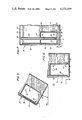
- FIG. 2 is a partially sectioned end view of a one of the disposal ink cartridge with its integral printhead as viewed from the recording medium.
- FIG. 3 is a partially sectioned, side view of the ink cartridge shown in FIG. 2 showing the secondary chamber and the passageway through which ink is fed to the printhead.
- FIG. 4 is a partially sectioned side view of an alternate embodiment of the cartridge of FIG. 3.
- FIG. 5 is a partially shown, enlarged cross-sectional view of the cartridge shown in FIG. 3 which shows the meniscus formed at the passageway entrance when the cartridge is tilted from the position as installed on the printer carriage by ⁇ degrees.
- FIG. 6 is a partially shown, cross-sectional view of another embodiment of the cartridge shown in FIG. 3.
- FIG. 7 is another partially shown side view of an alternate embodiment of the cartridge of FIG. 3.
- FIG. 8 is a further embodiment of the cartridge of FIG. 7.
- FIG. 9 is another embodiment of the cartridge of FIG. 3.
- a multicolor thermal ink jet printer 10 is shown.
- Several disposable ink supply cartridges 12, each with an integrally attached thermal printhead 11, are removably mounted on a translatable carriage.
- the carriage reciprocates back and forth on guide rails 15 as depicted by arrow 13.
- a recording medium 16, such as, for example, paper, is held stationary while the carriage is moving in one direction and, prior to the carriage moving in a reverse direction, the recording medium is stepped a distance equal to the height of the stripe of data printed on the recording medium by the thermal printheads.
- Each printhead has a linear array of nozzles which are aligned in a direction perpendicular to the reciprocating direction of the carriage.
- the nozzles confront the recording medium and is spaced therefrom a distance of between 0.01 and 0.2 inch. In the preferred embodiment this distance is about 0.02 inch.
- the nozzles center to center spacing is about 3 milli-inches (mils), so that 300 spots or pixels per inch may be printed on the recording medium.
- the thermal printhead propels ink droplets 18 toward the recording medium whenever droplets are required, during the traverse of the carriage to print information.
- the signal carrying ribbon cables attached to terminals of the printheads have been omitted for clarity.
- the required number of nozzles is a design choice based upon the desired number of traverses back and forth across the recording medium to print a full page of information. In the preferred embodiment, 40 to 64 nozzles are contemplated, so that the standard typewriter alphanumeric characters may be completely printed during one traverse of the carriage.
- Each cartridge 12 contains a different colored ink; one may be black and one to three additional cartridges may contain different selected colored inks. Such an arrangement permits black and white printing, color highlighting of basic black and white prints, or multiple colored prints. For multicolored printing, cyan, magenta and yellow colored inks would normally be used. Other combinations of cartridge colors could be used depending upon the user's needs, such as for example, two or three cartridges containing black ink and one or two cartridges containing red ink. Of course, a single cartridge 12 may be installed in the thermal ink jet printer 10, if single colored printing is desired.
- Each cartridge and printhead combination is removed and discarded after the ink supply in the cartridge has been depleted. This eliminates the need to refill the cartridge or replace printheads that have lifetimes of between 10 7 and 10 9 droplet firings per nozzle. This amounts to about 500-100 pages of data per cartridge.
- FIGS. 2 and 3 a front elevation view and a side elevation view of the cartridge 12 with an integrally attached thermal printhead 11 are shown, respectively.
- the front view is the one which confronts the recording medium when it is installed in the printer 10.
- Any plastic material such as, for example, "NOREL” a trademark for a thermoplastic material sold by the General Electric Company may be used for the cartridge material.
- the ink 17 is hermetically sealed within the cartridge 12 under a slight negative pressure in the range of 0.2 to 6 inches of water, with 1 to 4 inches being the preferred range.
- the cartridge holds between 20 and 40 cc, with 30 cc being the volume of ink in the preferred embodiment.
- An internal wall 20 forms a narrow passageway 36 for the ink to travel from the vicinity of the cartridge internal bottom 21 to an opening 22 in order to keep the printhead chamber 23 filled with ink.
- the passageway wall 20 is parallel to and spaced from the front cartridge wall 24 by the distance "b," and extends between the cartridge side walls 25, 26.
- the distance "b" is between 50-100 milli-inches (mils) in the preferred embodiment.
- the passageway wall 20 may extend to the cartridge top or stop at a location just above opening 22, as shown in the drawings.
- the bottom edge 27 of the passageway wall is parallel with the carriage internal bottom 21 and spaced therefrom a predetremined distance to form gap "a."
- the gap "a" may be between 5-100 mils, as shown in the drawing, or the gap may be substituted for a number of holes (not shown) having diameters of up to 10 mils.
- the gap or the plurality of holes may optionally be covered by a filter (not shown) to prevent particles or ink agglomerates from reaching and clogging the printhead nozzles 28.
- a secondary chamber or reservoir 29 is formed in the cartridge 12 by "L"-shaped wall 30 which is attached at one edge to passageway wall 20 and extends between the cartridge side walls 25, 26.
- the leg 31 of L-shaped wall 30 whose edge is attached to the passageway wall is parallel to the cartridge internal bottom 21.
- the edge 32 of the other leg of L-shaped wall 30 forms a gap “c" with the cartridge bottom 21.
- This gap "c” must be larger than gap "a” and preferably is in the range of 50 to 300 mils.
- the distance “d” between the L-shaped wall edge 32 and the cartridge back wall 33 must be at least 100 mils.
- the purpose of the cartridge secondary reservoir 29 is to maintain a volume of air at atmospheric pressure.
- This membrane filter allows the passage of air and gases therethrough, but is imprevious to the ink 17.
- Porous PTFE membrane or laminates thereof may be used as the membrane filter and is readily available from the companies of W. L. Gore Associates, Inc. or Garlock, Inc.
- the precise shape of the cartridge 12, passageway 36 and secondary reservoir 29 is not important, so long as the gaps "a” and “c” are maintained and the passageway 36 provides the appropriate constriction of the flow of ink to control the evaporation of the volatile components of the ink. Capillary ink feeding action by the passageway 36 is not required. Also, the minimum spacing (distance "d") between the secondary reservoir and cartridge back wall 33 must be observed to enable proper functioning of the cartridge during use as explained later. Therefore, the cartridge and integral thermal printhead may be reshaped as required to fit around components of printers of different construction during installation into carriage and translation during the printing mode or operation.
- FIG. 4 shows an alternate embodiment of the cartridge depicted in FIGS. 2 and 3.
- a pocket 38 of air having the same negative pressure as that of the main portion of the cartridge is located at the upper end of passageway 36.
- the ink 17 has a level 39 with the air pocket 38 above it.
- the level drops to that lower dashed line level 40 because of the fluid inertia of the ink and the frictional forces between the ink and the surfaces of the passageway 36.
- the reverse situation occurs when the printhead is discharging droplets then suddenly stops. The ink surges upward in the passageway to level 41, depicted in dashed line.
- the air pocket 38 may also be incorporated into the printhead chamber 23, but the pocket must never drop as low as the first nozzle 28a (see FIG. 3). Therefore, the printhead chamber should have additional height above the first nozzle, if this alternate feature of having an air pocket near the nozzles is utilized to prevent transient conditions at initiation or termination of the droplet propelling operation by the printhead.
- a breakaway seal 42 is formed to fill gap "c" as an alternate embodiment for shipment and pre-installation handling. Until the cartridge 12 with its integral printhead 11 is ready for installation, the danger of ink leaking through the printhead nozzles in case the cartridge is laid on its side 25 or 26 or stored upside down is eliminated.
- the breakaway seal 42 could be removed in a number of well known methods such as, for example, by inserting a pin (not shown) through a self-sealing material (not shown) covering an opening in a cartridge wall also not shown. The pin would break the seal 42 at the edge 32 of the L-shaped wall 30 that forms the gap "c" with the cartridge internal bottom 21.
- the seal Upon withdrawal of the pin, the seal seals itself and prevents the intake of atmospheric air into the slightly negative environment of the cartridge. Since the secondary reservoir 29 of the cartridge is destined to house an air bubble at atmospheric pressure during use, the self-sealing seal could be incorporated in the cartridge walls that forms the secondary reservoir. This would prevent risk of breach of integrity of the hermetically sealed cartridge.
- FIG. 7 Another embodiment is shown in FIG. 7.
- a small tube 44 penetrates leg 31 of the L-shaped wall 30 and extends parallel to the passageway 36 between the bottom edge 32 of the L-shaped wall 30 that forms the gap "c."
- the gaps "a" and “c" have the same dimensional distances as the embodiments of FIGS. 2 and 3.
- the secondary cartridge reservoir 29 is sealed against the ink 17 by a membrane diaphragm 50 which rests against the bottom end 45 of the tube, thus providing a seal between the air at atmospheric pressure in the secondary reservoir 29 and the air at a negative pressure at the top of the cartridge that communicates with the other end 46 of the tube 44.
- consumption of the ink in the passageway 36 by the printhead causes the diaphragm to flex downward momentarily to dashed line 51 to release a bubble of air at atmospheric pressure up the tube 44 into the negative pressure air space 43 above the ink in the main portion of the cartridge.
- the negative pressure is increased enough to enable the diaphragm to return to its normal position to seal again the tube end 45.
- FIG. 7 An optional modification to the embodiment of FIG. 7 is available by placing a temporary seal 48 over the tube end 45 which may be passively removed or broken when seated on the carriage by any well known means. The removal or breakage of the seal 48 must be done without penetrating the flexible diaphragm 50.
- FIG. 8 shows another modification of the embodiment of FIG. 7.
- the tube end in air space 43 has been modified to a bell-shaped opening 58 having annular flange 59 covered by a membrane 60 which has a material similar to that of the membrane 35 that covers cartridge aperture 34.
- Membrane 60 and diaphragm 50 eliminate the need for membrane 35, since dust or other contaminating particles cannot reach the ink.
- aperture 34 may remain open and uncovered during operation, but may be optionally sealed by a removable cover (not shown) prior to installation in printer 10.
- a tube 44 in the main embodiment of FIGS. 2 and 3, shown in FIG. 9 provides another embodiment.
- the only other modification is that the gap "c" may be closer or equal to the distance of gap "a" and that the tube end 45 be spaced from the cartridge bottom 21 a distance "e,” so that the tube end 45 is parallel to and spaced from the cartridge internal bottom 21 by between 50 to 300 mils. Therefore, the ink 17 normal closes the tube end 45, but momentary drops in the ink level in the secondary reservoir 29 permit a bubble of air to escape up the tube 44. Once the released bubble enters the space 43, the pressure in space 43, though still at a negative pressure, is increased enough to cause the ink level in the secondary reservoir 29 to rise and cover the tube end 45. The process is continually repeated as the ink is depleted during the printing mode.
- FIG. 5 shows that when the main embodiment of FIGS. 2 and 3 is rotated relative to a plane 49 parallel with that of the carriage 14 through an angle ⁇ , a meniscus 52 is formed at gap "a" which prevents air from the reservoir 29 from moving up the passageway 36 and reaching the printhead nozzles. Any air that reaches the nozzles would prevent proper operation of the printhead and could necessitate the early disposal of the cartridge and printhead even though the ink therein was not depleted.
- the thermal printhead operation and construction is similar to that of copending patent application Ser. No. 588,166 filed Mar. 9, 1984 by W. G. Hawkins and assigned to the assignee of the present invention.
- the operating sequence of the bubble jet system starts with a current pulse of predetermined duration through the resistor or resistive layer in the ink filled channel, the resistive layer being near the orifice or nozzle for that channel. Heat is transferred from the resistor to the ink.
- the ink becomes superheated (far above its normal boiling point) and for water based ink, finally reaches the critical temperature for bubble nucleation of around 280° C. Once nucleated, the bubble or water vapor thermally isolates the ink from the heater and no further heat can be applied to the ink.
- the bubble expands until all the heat stored in the ink, in excess of the normal boiling point, diffuses a way or is used to convert liquid to vapor which, of course, removes heat due to heat of vaporization.
- the expansion of the bubble forces a droplet of ink out of the nozzle.
- the bubble collapses on the resistor.
- the resistor at this point is no longer being heated because the current pulse has passed and, concurrently with the bubble collapse, the droplet is propelled at a high rate of speed in a direction towards a recording medium.
- the resistive layer encounters a severe cavitational force by the collapse of the bubble.
- the ink channel then refills by capillary action from the chamber 23.
- the entire bubble formation and collapse sequence occurs in about 10-50 microseconds.
- the channel can be refired after 50 to 500 microseconds minimum dwell time to enable the channel to be refilled and to enable the dynamic refilling factors to become somewhat dampened.
- the printhead comprises two different substrates of material, such as silicon.
- One substrate 55 has a recess with an opening 22 through the bottom thereof. Parallel grooves are formed which extend between one edge of the substrate and the recess; the grooves are about 13 mils long and have an axial spacing of approximately 3 mils.
- the other substrate 56 has a linear array of small resistors with individual electrodes and a common return patterned on one surface. The electrodes and the return extend to at least one edge of substrate 56 and terminate with terminal connectors suitable for attachment of ribbon cable 19.
- the two substrates are aligned and fixedly attached to each other, so that the surface of substrate 56 having the resistors match the exit regions of the grooves in substrate 55.
- the grooves and recess of substrate 55 form the nozzles 28, channels 37, and chamber 23 when covered by the substrate 56.
- the assembled printhead is permanently and sealingly attached to the cartridge 12 with substrate 55 contacting cartridge wall 26 and the hole opening 22 in the cartridge being aligned and axially coincident with the opening 22 of substrate 55.
- the ink in the printhead chamber 23 is replenished via the opening 22 from the cartridge passageway 36.
- the cartridges 12 with integral thermal printheads 11 are readily mounted on the printer carriage 14 and replaced with new cartridge/printheads when the ink supply therein is depleted by a user of the printer 10.
- Each cartridge may be between 0.5 and 1.5 inches thick.
- the cartridges are 0.6 inches thick and a portion of the cartridge has a thinner width at its upper portion to provide clearance for the printheads when a number of cartridges are mounted in juxtaposed position on the carriage.
- the ink supplies in each cartridge has been determined to last less than the lifetimes of the printhead resistors which deteriorate with use. When the ink in the cartridge has been depleted, the useful printhead lifetime is approached and the cartridge/printhead combination is removed from the printer and discarded.
- the carriage is optionally periodically translated to one side of the recording medium and ink droplets are expelled from all nozzles into a gutter not shown.
- the guide rails 15 must be long enough to enable the carriage to translate in each direction a distance sufficient to enable each printhead to print across the full width of the recording medium. If a gutter is desired in the printer 10 for periodic firing to maintain the nozzles free of dried ink in the unused nozzles, then the guide rails, of course, extend further to enable each printhead to propel droplets in the gutter.
- the present invention relates to a disposable ink cartridge and integral thermal printhead.
- the ink pressure in the printhead nozzles are maintained at a predetermined negative pressure, while the level of the ink in the cartridge is changing as the ink is spent.
- This predetermined negative pressure is obtained by a hermetically sealed, self-contained quantity of ink in a cartridge having an ink restricting passageway between the nozzles and the bottom of the cartridge.
- An air pocket at a location near the passageway entrance is maintained at atmospheric pressure in a small reservoir adapted to periodically leak air into the main ink supply in the cartridge to keep the desired negative pressure in the cartridge in equilibrium condition as the ink supply is depleted.
- the passageway isolates the pressure transients generated by the carriage motion and its entrance is designed to maintain a meniscus to prevent the ingestion of air if the cartridge is tilted prior to installation in the printer.
- the printhead chamber and opening between the chamber and passageway prevents crosstalk between nozzles as they are individually addressed to expel droplets.
- means are provided to prevent loss of the negative pressure at the nozzles caused by effects of fluid inertia of the ink which is present when sudden changes of printing duty cycle such as initial printing and stoppage of printing occurs.
Abstract
Description
Claims (13)
Priority Applications (4)
| Application Number | Priority Date | Filing Date | Title |
|---|---|---|---|
| US06/677,426 US4571599A (en) | 1984-12-03 | 1984-12-03 | Ink cartridge for an ink jet printer |
| JP60263971A JPH0811446B2 (en) | 1984-12-03 | 1985-11-26 | Inkjet printer ink cartridge |
| DE8585308600T DE3579298D1 (en) | 1984-12-03 | 1985-11-27 | INK CARTRIDGE FOR AN INK JET PRINTER. |
| EP85308600A EP0184376B1 (en) | 1984-12-03 | 1985-11-27 | Ink cartridge for an ink jet printer |
Applications Claiming Priority (1)
| Application Number | Priority Date | Filing Date | Title |
|---|---|---|---|
| US06/677,426 US4571599A (en) | 1984-12-03 | 1984-12-03 | Ink cartridge for an ink jet printer |
Publications (1)
| Publication Number | Publication Date |
|---|---|
| US4571599A true US4571599A (en) | 1986-02-18 |
Family
ID=24718654
Family Applications (1)
| Application Number | Title | Priority Date | Filing Date |
|---|---|---|---|
| US06/677,426 Expired - Lifetime US4571599A (en) | 1984-12-03 | 1984-12-03 | Ink cartridge for an ink jet printer |
Country Status (4)
| Country | Link |
|---|---|
| US (1) | US4571599A (en) |
| EP (1) | EP0184376B1 (en) |
| JP (1) | JPH0811446B2 (en) |
| DE (1) | DE3579298D1 (en) |
Cited By (142)
| Publication number | Priority date | Publication date | Assignee | Title |
|---|---|---|---|---|
| US4612554A (en) * | 1985-07-29 | 1986-09-16 | Xerox Corporation | High density thermal ink jet printhead |
| US4638337A (en) * | 1985-08-02 | 1987-01-20 | Xerox Corporation | Thermal ink jet printhead |
| US4639748A (en) * | 1985-09-30 | 1987-01-27 | Xerox Corporation | Ink jet printhead with integral ink filter |
| EP0243922A1 (en) * | 1986-04-28 | 1987-11-04 | W.L. Gore & Associates GmbH | Ink cartridge with a ventilation unit |
| US4709244A (en) * | 1986-12-22 | 1987-11-24 | Eastman Kodak Company | System for determining orifice interspacings of cooperative ink jet print/cartridges |
| US4709245A (en) * | 1986-12-22 | 1987-11-24 | Eastman Kodak Company | Ink jet printer for cooperatively printing with a plurality of insertable print/cartridges |
| US4709247A (en) * | 1986-12-22 | 1987-11-24 | Eastman Kodak Company | High resolution, print/cartridge ink, jet printer |
| US4709248A (en) * | 1986-12-22 | 1987-11-24 | Eastman Kodak Company | Transverse printing control system for multiple print/cartridge printer |
| US4709246A (en) * | 1986-12-22 | 1987-11-24 | Eastman Kodak Company | Adjustable print/cartridge ink jet printer |
| USRE32572E (en) * | 1985-04-03 | 1988-01-05 | Xerox Corporation | Thermal ink jet printhead and process therefor |
| US4750009A (en) * | 1985-05-09 | 1988-06-07 | Sharp Kabushiki Kaisha | Color ink jet system printer capable of high definition printing |
| WO1988004609A1 (en) * | 1986-12-22 | 1988-06-30 | Eastman Kodak Company | Multiple print/cartridge ink jet printer having accurate vertical interpositioning |
| WO1988008515A1 (en) * | 1987-04-28 | 1988-11-03 | Spectra, Inc. | Deaeration of ink in an ink jet system |
| US4786357A (en) * | 1987-11-27 | 1988-11-22 | Xerox Corporation | Thermal ink jet printhead and fabrication method therefor |
| US4797692A (en) * | 1987-09-02 | 1989-01-10 | Xerox Corporation | Thermal ink jet printer having ink nucleation control |
| US4829324A (en) * | 1987-12-23 | 1989-05-09 | Xerox Corporation | Large array thermal ink jet printhead |
| US4831390A (en) * | 1988-01-15 | 1989-05-16 | Xerox Corporation | Bubble jet printing device with improved printhead heat control |
| US4833491A (en) * | 1988-06-15 | 1989-05-23 | Xerox Corporation | Thermal ink jet printer adapted to operate in monochrome, highlight or process color modes |
| US4851371A (en) * | 1988-12-05 | 1989-07-25 | Xerox Corporation | Fabricating process for large array semiconductive devices |
| US4864329A (en) * | 1988-09-22 | 1989-09-05 | Xerox Corporation | Fluid handling device with filter and fabrication process therefor |
| US4920362A (en) * | 1988-12-16 | 1990-04-24 | Hewlett-Packard Company | Volumetrically efficient ink jet pen capable of extreme altitude and temperature excursions |
| WO1990005892A1 (en) * | 1988-11-18 | 1990-05-31 | Spectra, Inc. | Removal of dissolved gas from ink in an ink jet system |
| US4935750A (en) * | 1989-08-31 | 1990-06-19 | Xerox Corporation | Sealing means for thermal ink jet printheads |
| WO1990010845A1 (en) * | 1989-03-06 | 1990-09-20 | Spectra, Inc. | Ink supply system for an ink jet head |
| US4961076A (en) * | 1987-10-28 | 1990-10-02 | Hewlett-Packard Company | Reliability improvement for ink jet pens |
| US4992802A (en) * | 1988-12-22 | 1991-02-12 | Hewlett-Packard Company | Method and apparatus for extending the environmental operating range of an ink jet print cartridge |
| US4994824A (en) * | 1988-12-16 | 1991-02-19 | Hewlett-Packard Company | Modal ink jet printing system |
| US4995940A (en) * | 1988-11-18 | 1991-02-26 | Spectra, Inc. | Method for forming a gas removing device for an ink jet system |
| US4998120A (en) * | 1988-04-06 | 1991-03-05 | Seiko Epson Corporation | Hot melt ink jet printing apparatus |
| US5021809A (en) * | 1986-11-19 | 1991-06-04 | Canon Kabushiki Kaisha | Ink jet recording device with pressure-fluctuation absorption |
| US5036337A (en) * | 1990-06-22 | 1991-07-30 | Xerox Corporation | Thermal ink jet printhead with droplet volume control |
| US5039999A (en) * | 1990-06-26 | 1991-08-13 | Hewlett-Packard Company | Accumulator and pressure control for ink-ket pens |
| US5047790A (en) * | 1990-01-12 | 1991-09-10 | Hewlett-Packard Company | Controlled capillary ink containment for ink-jet pens |
| US5051761A (en) * | 1990-05-09 | 1991-09-24 | Xerox Corporation | Ink jet printer having a paper handling and maintenance station assembly |
| US5059989A (en) * | 1990-05-16 | 1991-10-22 | Lexmark International, Inc. | Thermal edge jet drop-on-demand ink jet print head |
| US5065170A (en) * | 1990-06-22 | 1991-11-12 | Xerox Corporation | Ink jet printer having a staggered array printhead |
| US5099256A (en) * | 1990-11-23 | 1992-03-24 | Xerox Corporation | Ink jet printer with intermediate drum |
| US5107276A (en) * | 1989-07-03 | 1992-04-21 | Xerox Corporation | Thermal ink jet printhead with constant operating temperature |
| US5138332A (en) * | 1990-10-29 | 1992-08-11 | Xerox Corporation | Ink jet printing apparatus |
| US5233369A (en) * | 1990-12-27 | 1993-08-03 | Xerox Corporation | Method and apparatus for supplying ink to an ink jet printer |
| US5245362A (en) * | 1990-02-13 | 1993-09-14 | Canon Kabushiki Kaisha | Ink jet recording apparatus with discharge recovery apparatus having varying driving force |
| US5257044A (en) * | 1992-11-12 | 1993-10-26 | Xerox Corporation | Cap actuation mechanism for capping ink jet printheads |
| EP0580433A1 (en) * | 1992-07-24 | 1994-01-26 | Canon Kabushiki Kaisha | Ink jet cartridge, ink jet head and printer |
| US5329306A (en) * | 1992-11-12 | 1994-07-12 | Xerox Corporation | Waste ink separator for ink jet printer maintenance system |
| US5339102A (en) * | 1992-11-12 | 1994-08-16 | Xerox Corporation | Capping carriage for ink jet printer maintenance station |
| US5341160A (en) * | 1991-04-17 | 1994-08-23 | Hewlett-Packard Corporation | Valve for ink-jet pen |
| US5351073A (en) * | 1991-04-25 | 1994-09-27 | Canon Kabushiki Kaisha | Ink jet cartridge with an ink tank having an ink outlet in a sloped surface |
| US5363130A (en) * | 1991-08-29 | 1994-11-08 | Hewlett-Packard Company | Method of valving and orientation sensitive valve including a liquid for controlling flow of gas into a container |
| US5382963A (en) * | 1992-09-21 | 1995-01-17 | Xerox Corporation | Ink jet printer for magnetic image character recognition printing |
| US5396271A (en) * | 1992-11-12 | 1995-03-07 | Xerox Corporation | Wiper blade cleaning system for non-coplanar nozzle faces of ink jet printheads |
| US5402156A (en) * | 1992-06-29 | 1995-03-28 | Xerox Corporation | Slow scan stitching mechanism |
| US5404158A (en) * | 1992-11-12 | 1995-04-04 | Xerox Corporation | Ink jet printer maintenance system |
| US5426459A (en) * | 1992-12-22 | 1995-06-20 | Hewlett-Packard Company | Combined filter/aircheck valve for thermal ink-jet pen |
| US5432538A (en) * | 1992-11-12 | 1995-07-11 | Xerox Corporation | Valve for an ink jet printer maintenance system |
| US5435961A (en) * | 1994-01-14 | 1995-07-25 | Xerox Corporation | Method and tool for forming a patterned gasket |
| US5451995A (en) * | 1992-12-22 | 1995-09-19 | Hewlett-Packard Company | Rigid loop case structure for thermal ink-jet pen |
| US5491502A (en) * | 1992-12-22 | 1996-02-13 | Hewlett-Packard Company | Thin pen structure for thermal ink-jet printer |
| EP0699137A1 (en) * | 1994-03-21 | 1996-03-06 | Spectra, Inc. | Simplified ink jet head |
| EP0704308A1 (en) * | 1994-09-24 | 1996-04-03 | PMS GmbH, Produktion + Recycling von Büromaschinenzubehör | Printhead for an ink jet printer and device for refilling such a printhead |
| US5509140A (en) * | 1992-07-24 | 1996-04-16 | Canon Kabushiki Kaisha | Replaceable ink cartridge |
| US5537134A (en) * | 1990-01-12 | 1996-07-16 | Hewlett-Packard Company | Refill method for ink-jet print cartridge |
| US5548310A (en) * | 1994-10-17 | 1996-08-20 | Xerox Corporation | Automatic positioning of wiper blades in an ink jet printer maintenance station |
| US5572245A (en) * | 1994-03-10 | 1996-11-05 | Hewlett-Packard Company | Protective cover apparatus for an ink-jet pen |
| US5585825A (en) * | 1994-11-25 | 1996-12-17 | Xerox Corporation | Ink jet printer having temperature sensor for replaceable printheads |
| EP0761451A1 (en) * | 1995-08-23 | 1997-03-12 | Seiko Epson Corporation | Ink tank |
| EP0780822A1 (en) | 1995-12-20 | 1997-06-25 | Philips Patentverwaltung GmbH | Method and device for contactless transmission of measured values |
| FR2743334A1 (en) * | 1996-01-10 | 1997-07-11 | Neopost Ind | INK TANK INTEGRATED WITH A MAILING POST |
| US5682184A (en) * | 1995-12-18 | 1997-10-28 | Xerox Corporation | System for sensing ink level and type of ink for an ink jet printer |
| US5686943A (en) * | 1994-11-25 | 1997-11-11 | Xerox Corporation | Ink jet printer having temperature sensor for periodic contact with printhead |
| EP0684136A3 (en) * | 1994-05-25 | 1998-02-25 | Canon Kabushiki Kaisha | An ink container |
| US5731824A (en) * | 1995-12-18 | 1998-03-24 | Xerox Corporation | Ink level sensing system for an ink jet printer |
| US5739830A (en) * | 1995-01-05 | 1998-04-14 | Xerox Corporation | Monolithic printheads for ink jet printing apparatus |
| US5742312A (en) * | 1994-11-03 | 1998-04-21 | Xerox Corporation | Printhead cartridge having a fluid valved breather |
| US5745130A (en) * | 1995-12-11 | 1998-04-28 | Xerox Corporation | System for sensing the temperature of a printhead in an ink jet printer |
| US5754204A (en) * | 1995-02-23 | 1998-05-19 | Seiko Epson Corporation | Ink jet recording head |
| US5757406A (en) * | 1992-08-12 | 1998-05-26 | Hewlett-Packard Company | Negative pressure ink delivery system |
| US5760805A (en) * | 1996-06-24 | 1998-06-02 | Xerox Corporation | Ink supply container with improved foam retention properties |
| US5786829A (en) * | 1996-07-01 | 1998-07-28 | Xerox Corporation | Apparatus and method for cleaning an ink flow path of an ink jet printhead |
| US5801727A (en) * | 1996-11-04 | 1998-09-01 | Xerox Corporation | Apparatus and method for printing device |
| EP0869658A2 (en) | 1997-03-31 | 1998-10-07 | Xerox Corporation | Ink jet printer having multiple level grayscale printing |
| US5821966A (en) * | 1996-06-17 | 1998-10-13 | Xerox Corporation | Ink jet cartridge with improved sealing between ink container and printhead |
| US5831649A (en) * | 1996-05-17 | 1998-11-03 | Xerox Corporation | Thermal ink jet printing system including printhead with electronically encoded identification |
| US5850237A (en) * | 1996-06-26 | 1998-12-15 | Xerox Corporation | Method and device for selective recording head maintenance for an ink recording apparatus |
| US5852458A (en) * | 1991-08-27 | 1998-12-22 | Hewlett-Packard Company | Inkjet print cartridge having a first inlet port for initial filling and a second inlet port for ink replenishment without removing the print cartridge from the printer |
| US5867195A (en) * | 1987-03-20 | 1999-02-02 | Canon Kabushiki Kaisha | Ink jet recording apparatus and recording head having an air chamber defining a closed space in communication with a liquid chamber |
| EP0897804A2 (en) | 1997-08-15 | 1999-02-24 | Xerox Corporation | Liquid ink printhead |
| US5883655A (en) * | 1996-09-09 | 1999-03-16 | Xerox Corporation | Copy sheet stacking apparatus with articulated exit guide ramp |
| US5881451A (en) * | 1996-06-21 | 1999-03-16 | Xerox Corporation | Sensing the temperature of a printhead in an ink jet printer |
| US5886721A (en) * | 1984-08-23 | 1999-03-23 | Fuji Xerox Co., Ltd. | Method and device for supplying ink to a print head |
| US5900898A (en) * | 1992-12-25 | 1999-05-04 | Canon Kabushiki Kaisha | Liquid jet head having a contoured and secured filter, liquid jet apparatus using same, and method of immovably securing a filter to a liquid receiving member of a liquid jet head |
| US5901425A (en) | 1996-08-27 | 1999-05-11 | Topaz Technologies Inc. | Inkjet print head apparatus |
| USD410949S (en) * | 1997-05-14 | 1999-06-15 | Intermec Printer Ab | Printer head |
| US5917523A (en) * | 1990-01-12 | 1999-06-29 | Hewlett-Packard Company | Refill method for ink-jet print cartridge |
| US5923347A (en) * | 1997-01-24 | 1999-07-13 | Xerox Corporation | Method and system for cleaning an ink jet printhead |
| NL1008040C2 (en) | 1998-01-16 | 1999-07-19 | Oce Tech Bv | Ink supply holder suitable for connection to an inkjet printhead as well as a system of such an ink supply holder and an inkjet printhead. |
| US5943071A (en) * | 1995-12-07 | 1999-08-24 | Xerox Corporation | Wiper blade cleaning system for nozzle faces of a color printhead |
| EP0947329A2 (en) | 1998-04-06 | 1999-10-06 | Xerox Corporation | Ink supply container for an ink jet printhead |
| EP0949080A2 (en) | 1998-04-06 | 1999-10-13 | Xerox Corporation | Ink container with improved sealing of ink container outlet port |
| US5967045A (en) * | 1998-10-20 | 1999-10-19 | Imation Corp. | Ink delivery pressure control |
| US5971531A (en) * | 1997-10-08 | 1999-10-26 | Xerox Corporation | Ink jet cartridge having replaceable ink supply tanks with an internal filter |
| US5992978A (en) * | 1994-04-20 | 1999-11-30 | Seiko Epson Corporation | Ink jet recording apparatus, and an ink jet head manufacturing method |
| US5997121A (en) * | 1995-12-14 | 1999-12-07 | Xerox Corporation | Sensing system for detecting presence of an ink container and level of ink therein |
| US6042225A (en) * | 1994-10-31 | 2000-03-28 | Hewlett-Packard Company | Ink-jet pen with one-piece pen body |
| US6068365A (en) * | 1991-10-21 | 2000-05-30 | Canon Kabushiki Kaisha | Color ink jet recording apparatus with recording head arranged at shifted position |
| US6069710A (en) * | 1996-12-23 | 2000-05-30 | Samsung Electronics Co., Ltd. | Circuit and method for controlling print heads of ink-jet printer |
| US6106088A (en) * | 1997-10-01 | 2000-08-22 | Xerox Corporation | Printhead assembly with integral lifetime monitoring system |
| US6130684A (en) * | 1998-12-09 | 2000-10-10 | Xerox Corporation | Maintenance station for an ink jet printhead with improved capping and wiping system |
| WO2000071348A1 (en) * | 1999-05-25 | 2000-11-30 | Silverbrook Research Pty. Ltd. | Printer consumable cartridge with air filter |
| US6158837A (en) * | 1997-09-19 | 2000-12-12 | Xerox Corporation | Printer having print mode for non-qualified marking material |
| US6196671B1 (en) | 1999-12-20 | 2001-03-06 | Xerox Corporation | Ink-jet cartridge for an ink jet printer having air ingestion control |
| US6199979B1 (en) | 1997-01-21 | 2001-03-13 | Gore Enterprise Holdings, Inc. | Ink filter element for printers |
| US6214279B1 (en) | 1999-10-02 | 2001-04-10 | Nanotek Instruments, Inc. | Apparatus and process for freeform fabrication of composite reinforcement preforms |
| US6286944B1 (en) * | 1993-05-21 | 2001-09-11 | Canon Kabushiki Kaisha | Ink jet unit with cartridge having controlled ink flow |
| US6312083B1 (en) | 1999-12-20 | 2001-11-06 | Xerox Corporation | Printhead assembly with ink monitoring system |
| US6332675B1 (en) | 1992-07-24 | 2001-12-25 | Canon Kabushiki Kaisha | Ink container, ink and ink jet recording apparatus using ink container |
| US6338544B1 (en) | 1999-06-29 | 2002-01-15 | Xerox Corporation | Reduction of stitch joint error by alternating print head firing mode |
| US6357852B1 (en) | 1998-06-16 | 2002-03-19 | Xerox Corporation | Method and apparatus for restoring an ink jet printhead |
| US6371598B1 (en) | 1994-04-20 | 2002-04-16 | Seiko Epson Corporation | Ink jet recording apparatus, and an ink jet head |
| US6402280B2 (en) | 1999-01-19 | 2002-06-11 | Xerox Corporation | Printhead with close-packed configuration of alternating sized drop ejectors and method of firing such drop ejectors |
| US6406115B2 (en) | 1999-01-19 | 2002-06-18 | Xerox Corporation | Method of printing with multiple sized drop ejectors on a single printhead |
| US6450627B1 (en) * | 1994-03-21 | 2002-09-17 | Spectra, Inc. | Simplified ink jet head |
| US6491368B1 (en) | 2001-12-03 | 2002-12-10 | Xerox Corporation | Priming system for multicolor ink jet printers |
| FR2827682A1 (en) * | 2001-07-20 | 2003-01-24 | Gemplus Card Int | Pressure regulation by transfer of a measured volume of gas, uses addition or removal of volume of gas above ink in an ink reservoir to control pressure in reservoir |
| US6520612B1 (en) | 2001-03-26 | 2003-02-18 | Xerox Corporation | Sensing system for detecting presence of an ink container |
| US6578942B1 (en) | 2002-04-10 | 2003-06-17 | Xerox Corporation | Liquid crystal sensing of thermal ink jet head temperature |
| US6595611B1 (en) | 2002-10-01 | 2003-07-22 | Xerox Corporation | Ink ejection tracking for controlling printhead nozzle maintenance |
| US6652086B1 (en) * | 1999-10-08 | 2003-11-25 | Canon Kabushiki Kaisha | Image erasing device, and image display apparatus and image recording apparatus equipped with the image erasing device |
| US20040080592A1 (en) * | 2002-10-29 | 2004-04-29 | Xerox Corporation | Conical or cylindrical laser ablated filter |
| US20040085435A1 (en) * | 2002-10-30 | 2004-05-06 | Xerox Corporation | Pleated laser ablated filter |
| US20040095407A1 (en) * | 1998-11-26 | 2004-05-20 | Seiko Epson Corporation | Printer and ink cartridge attached thereto |
| US20040165047A1 (en) * | 1997-03-28 | 2004-08-26 | Brother Kogyo Kabushiki Kaisha | Ink jet head capable of reliably removing air bubbles from ink |
| US20050073560A1 (en) * | 2003-10-06 | 2005-04-07 | Gray Trevor D. | Semipermeable membrane for an ink reservoir and method of attaching the same |
| WO2005051665A1 (en) * | 2003-11-28 | 2005-06-09 | Print-Rite Unicorn Image Products Co., Ltd. Of Zhuhai | Cartridge for inkjet printer |
| US20050151798A1 (en) * | 2004-01-08 | 2005-07-14 | Fuji Xerox Co., Ltd. | Internal venting structure for fluid tanks |
| EP1561580A2 (en) * | 2004-02-06 | 2005-08-10 | Print-Rite Unicorn Image Products Co. Ltd of Zhuhai | A device for continuously supplying ink under constant pressure |
| US20050214673A1 (en) * | 2003-05-21 | 2005-09-29 | Xerox Corporation | Formation of novel ink jet filter printhead using transferable photopatterned filter layer |
| US7029108B2 (en) * | 2002-09-12 | 2006-04-18 | Hewlett-Packard Development Company, L.P. | Inkjet cartridge with tubular entrained ink chamber |
| US20060098037A1 (en) * | 2004-11-10 | 2006-05-11 | Xerox Corporation | Method and apparatus for reducing intercolor bleed to improve print quality |
| US20060137526A1 (en) * | 2004-12-28 | 2006-06-29 | Canon Kabushiki Kaisha | Liquid housing container and liquid supply apparatus |
| US20080303862A1 (en) * | 2007-05-11 | 2008-12-11 | Masaharu Ito | Liquid droplet jetting apparatus and recording apparatus |
| US20090160915A1 (en) * | 2007-12-19 | 2009-06-25 | Canon Finetech Inc. | Ink supplying apparatus, inkjet printing apparatus, inkjet printing head, ink supplying method and inkjet printing method |
| US10265910B2 (en) | 2010-10-27 | 2019-04-23 | Rize Inc. | Process and apparatus for fabrication of three-dimensional objects |
Families Citing this family (6)
| Publication number | Priority date | Publication date | Assignee | Title |
|---|---|---|---|---|
| US4833486A (en) * | 1987-07-08 | 1989-05-23 | Dataproducts Corporation | Ink jet image transfer lithographic |
| US4791438A (en) * | 1987-10-28 | 1988-12-13 | Hewlett-Packard Company | Balanced capillary ink jet pen for ink jet printing systems |
| JP3187870B2 (en) * | 1990-08-17 | 2001-07-16 | キヤノン株式会社 | Ink tank and ink jet recording apparatus using the ink tank |
| US5113199A (en) * | 1991-03-11 | 1992-05-12 | Hewlett-Packard Company | Ink delivery system for ink jet printers |
| US5489925A (en) * | 1993-05-04 | 1996-02-06 | Markem Corporation | Ink jet printing system |
| JP5167847B2 (en) * | 2007-11-09 | 2013-03-21 | セイコーエプソン株式会社 | Liquid container and method for manufacturing the same |
Citations (13)
| Publication number | Priority date | Publication date | Assignee | Title |
|---|---|---|---|---|
| AT212039B (en) * | 1958-08-21 | 1960-11-25 | Siemens Ag | Reservoir for ink pens |
| US3708798A (en) * | 1971-12-23 | 1973-01-02 | Ibm | Ink distribution for non-impact printing recorder |
| JPS54117503A (en) * | 1978-03-03 | 1979-09-12 | Hitachi Zosen Corp | Parallel flow-type reforming furnace |
| US4306245A (en) * | 1978-09-21 | 1981-12-15 | Canon Kabushiki Kaisha | Liquid jet device with cleaning protective means |
| US4342041A (en) * | 1979-08-15 | 1982-07-27 | Canon Kabushiki Kaisha | Ink jet type recording apparatus |
| US4383263A (en) * | 1980-05-20 | 1983-05-10 | Canon Kabushiki Kaisha | Liquid ejecting apparatus having a suction mechanism |
| US4419678A (en) * | 1979-10-17 | 1983-12-06 | Canon Kabushiki Kaisha | Ink jet recording apparatus |
| US4456916A (en) * | 1982-09-28 | 1984-06-26 | Burroughs Corporation | Ink jet cartridge with hydrostatic controller |
| US4463362A (en) * | 1982-06-07 | 1984-07-31 | Ncr Corporation | Ink control baffle plates for ink jet printer |
| US4500895A (en) * | 1983-05-02 | 1985-02-19 | Hewlett-Packard Company | Disposable ink jet head |
| US4509062A (en) * | 1982-11-23 | 1985-04-02 | Hewlett-Packard Company | Ink reservoir with essentially constant negative back pressure |
| US4511906A (en) * | 1982-10-13 | 1985-04-16 | Sharp Kabushiki Kaisha | Ink liquid reservoir in an ink jet system printer |
| US4532530A (en) * | 1984-03-09 | 1985-07-30 | Xerox Corporation | Bubble jet printing device |
Family Cites Families (2)
| Publication number | Priority date | Publication date | Assignee | Title |
|---|---|---|---|---|
| JPS5542877A (en) * | 1978-09-21 | 1980-03-26 | Canon Inc | Recording head cartridge |
| JPS59129161A (en) * | 1983-01-17 | 1984-07-25 | Seiko Epson Corp | Printer |
-
1984
- 1984-12-03 US US06/677,426 patent/US4571599A/en not_active Expired - Lifetime
-
1985
- 1985-11-26 JP JP60263971A patent/JPH0811446B2/en not_active Expired - Lifetime
- 1985-11-27 DE DE8585308600T patent/DE3579298D1/en not_active Expired - Fee Related
- 1985-11-27 EP EP85308600A patent/EP0184376B1/en not_active Expired - Lifetime
Patent Citations (13)
| Publication number | Priority date | Publication date | Assignee | Title |
|---|---|---|---|---|
| AT212039B (en) * | 1958-08-21 | 1960-11-25 | Siemens Ag | Reservoir for ink pens |
| US3708798A (en) * | 1971-12-23 | 1973-01-02 | Ibm | Ink distribution for non-impact printing recorder |
| JPS54117503A (en) * | 1978-03-03 | 1979-09-12 | Hitachi Zosen Corp | Parallel flow-type reforming furnace |
| US4306245A (en) * | 1978-09-21 | 1981-12-15 | Canon Kabushiki Kaisha | Liquid jet device with cleaning protective means |
| US4342041A (en) * | 1979-08-15 | 1982-07-27 | Canon Kabushiki Kaisha | Ink jet type recording apparatus |
| US4419678A (en) * | 1979-10-17 | 1983-12-06 | Canon Kabushiki Kaisha | Ink jet recording apparatus |
| US4383263A (en) * | 1980-05-20 | 1983-05-10 | Canon Kabushiki Kaisha | Liquid ejecting apparatus having a suction mechanism |
| US4463362A (en) * | 1982-06-07 | 1984-07-31 | Ncr Corporation | Ink control baffle plates for ink jet printer |
| US4456916A (en) * | 1982-09-28 | 1984-06-26 | Burroughs Corporation | Ink jet cartridge with hydrostatic controller |
| US4511906A (en) * | 1982-10-13 | 1985-04-16 | Sharp Kabushiki Kaisha | Ink liquid reservoir in an ink jet system printer |
| US4509062A (en) * | 1982-11-23 | 1985-04-02 | Hewlett-Packard Company | Ink reservoir with essentially constant negative back pressure |
| US4500895A (en) * | 1983-05-02 | 1985-02-19 | Hewlett-Packard Company | Disposable ink jet head |
| US4532530A (en) * | 1984-03-09 | 1985-07-30 | Xerox Corporation | Bubble jet printing device |
Cited By (212)
| Publication number | Priority date | Publication date | Assignee | Title |
|---|---|---|---|---|
| US5886721A (en) * | 1984-08-23 | 1999-03-23 | Fuji Xerox Co., Ltd. | Method and device for supplying ink to a print head |
| USRE32572E (en) * | 1985-04-03 | 1988-01-05 | Xerox Corporation | Thermal ink jet printhead and process therefor |
| US4750009A (en) * | 1985-05-09 | 1988-06-07 | Sharp Kabushiki Kaisha | Color ink jet system printer capable of high definition printing |
| US4612554A (en) * | 1985-07-29 | 1986-09-16 | Xerox Corporation | High density thermal ink jet printhead |
| US4638337A (en) * | 1985-08-02 | 1987-01-20 | Xerox Corporation | Thermal ink jet printhead |
| US4639748A (en) * | 1985-09-30 | 1987-01-27 | Xerox Corporation | Ink jet printhead with integral ink filter |
| EP0243922A1 (en) * | 1986-04-28 | 1987-11-04 | W.L. Gore & Associates GmbH | Ink cartridge with a ventilation unit |
| US5021809A (en) * | 1986-11-19 | 1991-06-04 | Canon Kabushiki Kaisha | Ink jet recording device with pressure-fluctuation absorption |
| US4709248A (en) * | 1986-12-22 | 1987-11-24 | Eastman Kodak Company | Transverse printing control system for multiple print/cartridge printer |
| US4709247A (en) * | 1986-12-22 | 1987-11-24 | Eastman Kodak Company | High resolution, print/cartridge ink, jet printer |
| WO1988004609A1 (en) * | 1986-12-22 | 1988-06-30 | Eastman Kodak Company | Multiple print/cartridge ink jet printer having accurate vertical interpositioning |
| US4709246A (en) * | 1986-12-22 | 1987-11-24 | Eastman Kodak Company | Adjustable print/cartridge ink jet printer |
| US4709245A (en) * | 1986-12-22 | 1987-11-24 | Eastman Kodak Company | Ink jet printer for cooperatively printing with a plurality of insertable print/cartridges |
| US4709244A (en) * | 1986-12-22 | 1987-11-24 | Eastman Kodak Company | System for determining orifice interspacings of cooperative ink jet print/cartridges |
| US5867195A (en) * | 1987-03-20 | 1999-02-02 | Canon Kabushiki Kaisha | Ink jet recording apparatus and recording head having an air chamber defining a closed space in communication with a liquid chamber |
| US4961082A (en) * | 1987-04-28 | 1990-10-02 | Spectra, Inc. | Deaeration of ink in an ink jet system |
| WO1988008515A1 (en) * | 1987-04-28 | 1988-11-03 | Spectra, Inc. | Deaeration of ink in an ink jet system |
| US4788556A (en) * | 1987-04-28 | 1988-11-29 | Spectra, Inc. | Deaeration of ink in an ink jet system |
| US4797692A (en) * | 1987-09-02 | 1989-01-10 | Xerox Corporation | Thermal ink jet printer having ink nucleation control |
| US4961076A (en) * | 1987-10-28 | 1990-10-02 | Hewlett-Packard Company | Reliability improvement for ink jet pens |
| US4786357A (en) * | 1987-11-27 | 1988-11-22 | Xerox Corporation | Thermal ink jet printhead and fabrication method therefor |
| US4829324A (en) * | 1987-12-23 | 1989-05-09 | Xerox Corporation | Large array thermal ink jet printhead |
| US4831390A (en) * | 1988-01-15 | 1989-05-16 | Xerox Corporation | Bubble jet printing device with improved printhead heat control |
| US5105209A (en) * | 1988-04-06 | 1992-04-14 | Seiko Epson Corporation | Hot melt ink jet printing apparatus |
| US4998120A (en) * | 1988-04-06 | 1991-03-05 | Seiko Epson Corporation | Hot melt ink jet printing apparatus |
| US4833491A (en) * | 1988-06-15 | 1989-05-23 | Xerox Corporation | Thermal ink jet printer adapted to operate in monochrome, highlight or process color modes |
| US4864329A (en) * | 1988-09-22 | 1989-09-05 | Xerox Corporation | Fluid handling device with filter and fabrication process therefor |
| US4940995A (en) * | 1988-11-18 | 1990-07-10 | Spectra, Inc. | Removal of dissolved gas from ink in an ink jet system |
| WO1990005892A1 (en) * | 1988-11-18 | 1990-05-31 | Spectra, Inc. | Removal of dissolved gas from ink in an ink jet system |
| US4995940A (en) * | 1988-11-18 | 1991-02-26 | Spectra, Inc. | Method for forming a gas removing device for an ink jet system |
| US4851371A (en) * | 1988-12-05 | 1989-07-25 | Xerox Corporation | Fabricating process for large array semiconductive devices |
| US4994824A (en) * | 1988-12-16 | 1991-02-19 | Hewlett-Packard Company | Modal ink jet printing system |
| US4920362A (en) * | 1988-12-16 | 1990-04-24 | Hewlett-Packard Company | Volumetrically efficient ink jet pen capable of extreme altitude and temperature excursions |
| US4992802A (en) * | 1988-12-22 | 1991-02-12 | Hewlett-Packard Company | Method and apparatus for extending the environmental operating range of an ink jet print cartridge |
| WO1990010845A1 (en) * | 1989-03-06 | 1990-09-20 | Spectra, Inc. | Ink supply system for an ink jet head |
| US5107276A (en) * | 1989-07-03 | 1992-04-21 | Xerox Corporation | Thermal ink jet printhead with constant operating temperature |
| US4935750A (en) * | 1989-08-31 | 1990-06-19 | Xerox Corporation | Sealing means for thermal ink jet printheads |
| US5047790A (en) * | 1990-01-12 | 1991-09-10 | Hewlett-Packard Company | Controlled capillary ink containment for ink-jet pens |
| US5917523A (en) * | 1990-01-12 | 1999-06-29 | Hewlett-Packard Company | Refill method for ink-jet print cartridge |
| US5537134A (en) * | 1990-01-12 | 1996-07-16 | Hewlett-Packard Company | Refill method for ink-jet print cartridge |
| US6550888B2 (en) | 1990-02-13 | 2003-04-22 | Canon Kabushiki Kaisha | Recovery of ink jet recording apparatus using controlled suction of ink |
| EP0628414A3 (en) * | 1990-02-13 | 1995-01-04 | Canon Kk | |
| EP0628414A2 (en) * | 1990-02-13 | 1994-12-14 | Canon Kabushiki Kaisha | Ink jet recording apparatus |
| US5245362A (en) * | 1990-02-13 | 1993-09-14 | Canon Kabushiki Kaisha | Ink jet recording apparatus with discharge recovery apparatus having varying driving force |
| US6338541B1 (en) | 1990-02-13 | 2002-01-15 | Canon Kabushiki Kaisha | Ink jet recording apparatus with plural waste ink tanks |
| US5051761A (en) * | 1990-05-09 | 1991-09-24 | Xerox Corporation | Ink jet printer having a paper handling and maintenance station assembly |
| US5059989A (en) * | 1990-05-16 | 1991-10-22 | Lexmark International, Inc. | Thermal edge jet drop-on-demand ink jet print head |
| US5065170A (en) * | 1990-06-22 | 1991-11-12 | Xerox Corporation | Ink jet printer having a staggered array printhead |
| US5036337A (en) * | 1990-06-22 | 1991-07-30 | Xerox Corporation | Thermal ink jet printhead with droplet volume control |
| US5039999A (en) * | 1990-06-26 | 1991-08-13 | Hewlett-Packard Company | Accumulator and pressure control for ink-ket pens |
| US5138332A (en) * | 1990-10-29 | 1992-08-11 | Xerox Corporation | Ink jet printing apparatus |
| US5099256A (en) * | 1990-11-23 | 1992-03-24 | Xerox Corporation | Ink jet printer with intermediate drum |
| US5233369A (en) * | 1990-12-27 | 1993-08-03 | Xerox Corporation | Method and apparatus for supplying ink to an ink jet printer |
| US5341160A (en) * | 1991-04-17 | 1994-08-23 | Hewlett-Packard Corporation | Valve for ink-jet pen |
| US5351073A (en) * | 1991-04-25 | 1994-09-27 | Canon Kabushiki Kaisha | Ink jet cartridge with an ink tank having an ink outlet in a sloped surface |
| US5852458A (en) * | 1991-08-27 | 1998-12-22 | Hewlett-Packard Company | Inkjet print cartridge having a first inlet port for initial filling and a second inlet port for ink replenishment without removing the print cartridge from the printer |
| US5363130A (en) * | 1991-08-29 | 1994-11-08 | Hewlett-Packard Company | Method of valving and orientation sensitive valve including a liquid for controlling flow of gas into a container |
| US6068365A (en) * | 1991-10-21 | 2000-05-30 | Canon Kabushiki Kaisha | Color ink jet recording apparatus with recording head arranged at shifted position |
| US5402156A (en) * | 1992-06-29 | 1995-03-28 | Xerox Corporation | Slow scan stitching mechanism |
| US6394590B1 (en) | 1992-07-24 | 2002-05-28 | Canon Kabushiki Kaisha | Replaceable liquid container |
| CN1073510C (en) * | 1992-07-24 | 2001-10-24 | 佳能株式会社 | Ink jet cartridge, ink jet head and printer |
| EP0838340A3 (en) * | 1992-07-24 | 1998-07-08 | Canon Kabushiki Kaisha | Ink jet cartridge, ink jet head and printer |
| EP0580433A1 (en) * | 1992-07-24 | 1994-01-26 | Canon Kabushiki Kaisha | Ink jet cartridge, ink jet head and printer |
| US6688735B2 (en) | 1992-07-24 | 2004-02-10 | Canon Kabushiki Kaisha | Ink jet cartridge, ink jet head and printer |
| EP0838340A2 (en) * | 1992-07-24 | 1998-04-29 | Canon Kabushiki Kaisha | Ink jet cartridge, ink jet head and printer |
| US5509140A (en) * | 1992-07-24 | 1996-04-16 | Canon Kabushiki Kaisha | Replaceable ink cartridge |
| US5742311A (en) * | 1992-07-24 | 1998-04-21 | Canon Kabushiki Kaisha | Replaceable ink cartridge |
| US6474801B2 (en) | 1992-07-24 | 2002-11-05 | Canon Kabushiki Kaisha | Ink jet cartridge, ink jet head and printer |
| CN1087231C (en) * | 1992-07-24 | 2002-07-10 | 佳能株式会社 | Ink jetting tube, ink jetting head and printer |
| US6012808A (en) * | 1992-07-24 | 2000-01-11 | Canon Kabushiki Kaisha | Ink container, ink and ink jet recording apparatus using ink container |
| US6390578B1 (en) | 1992-07-24 | 2002-05-21 | Canon Kabushiki Kaisha | Ink container, ink and ink jet recording apparatus using ink container |
| US6095642A (en) * | 1992-07-24 | 2000-08-01 | Canon Kabushiki Kaisha | Ink container, ink and ink jet recording apparatus using ink container |
| US6123420A (en) * | 1992-07-24 | 2000-09-26 | Canon Kabushiki Kaisha | Container with negative pressure producing material |
| US5619238A (en) * | 1992-07-24 | 1997-04-08 | Canon Kabushiki Kaisha | Method of making replaceable ink cartridge |
| US6332675B1 (en) | 1992-07-24 | 2001-12-25 | Canon Kabushiki Kaisha | Ink container, ink and ink jet recording apparatus using ink container |
| US6332673B1 (en) | 1992-07-24 | 2001-12-25 | Canon Kabushiki Kaisha | Liquid container having reinforcing member |
| US6796643B2 (en) | 1992-07-24 | 2004-09-28 | Canon Kabushiki Kaisha | Ink jet cartridge, ink jet head and printer |
| US6299298B1 (en) | 1992-07-24 | 2001-10-09 | Canon Kabushiki Kaisha | Chambered liquid container having communication path |
| US6286945B1 (en) | 1992-07-24 | 2001-09-11 | Canon Kabushiki Kaisha | Ink jet cartridge, ink jet head and printer |
| US6231172B1 (en) | 1992-07-24 | 2001-05-15 | Canon Kabushiki Kaisha | Ink container, ink and ink jet recording apparatus using ink container |
| EP1075951A3 (en) * | 1992-07-24 | 2001-02-21 | Canon Kabushiki Kaisha | Ink jet cartridge, ink jet head and printer |
| US5757406A (en) * | 1992-08-12 | 1998-05-26 | Hewlett-Packard Company | Negative pressure ink delivery system |
| US5382963A (en) * | 1992-09-21 | 1995-01-17 | Xerox Corporation | Ink jet printer for magnetic image character recognition printing |
| US5432538A (en) * | 1992-11-12 | 1995-07-11 | Xerox Corporation | Valve for an ink jet printer maintenance system |
| US5404158A (en) * | 1992-11-12 | 1995-04-04 | Xerox Corporation | Ink jet printer maintenance system |
| US5339102A (en) * | 1992-11-12 | 1994-08-16 | Xerox Corporation | Capping carriage for ink jet printer maintenance station |
| US5396271A (en) * | 1992-11-12 | 1995-03-07 | Xerox Corporation | Wiper blade cleaning system for non-coplanar nozzle faces of ink jet printheads |
| US5329306A (en) * | 1992-11-12 | 1994-07-12 | Xerox Corporation | Waste ink separator for ink jet printer maintenance system |
| US5257044A (en) * | 1992-11-12 | 1993-10-26 | Xerox Corporation | Cap actuation mechanism for capping ink jet printheads |
| US5426459A (en) * | 1992-12-22 | 1995-06-20 | Hewlett-Packard Company | Combined filter/aircheck valve for thermal ink-jet pen |
| US5594483A (en) * | 1992-12-22 | 1997-01-14 | Hewlett-Packard Company | Ink-jet cartridge with ink filtration |
| US5491502A (en) * | 1992-12-22 | 1996-02-13 | Hewlett-Packard Company | Thin pen structure for thermal ink-jet printer |
| US5451995A (en) * | 1992-12-22 | 1995-09-19 | Hewlett-Packard Company | Rigid loop case structure for thermal ink-jet pen |
| US5870125A (en) * | 1992-12-22 | 1999-02-09 | Hewlett-Packard Company | Thin pen structure for thermal ink-jet printer |
| US5900898A (en) * | 1992-12-25 | 1999-05-04 | Canon Kabushiki Kaisha | Liquid jet head having a contoured and secured filter, liquid jet apparatus using same, and method of immovably securing a filter to a liquid receiving member of a liquid jet head |
| US6286944B1 (en) * | 1993-05-21 | 2001-09-11 | Canon Kabushiki Kaisha | Ink jet unit with cartridge having controlled ink flow |
| US5435961A (en) * | 1994-01-14 | 1995-07-25 | Xerox Corporation | Method and tool for forming a patterned gasket |
| US5572245A (en) * | 1994-03-10 | 1996-11-05 | Hewlett-Packard Company | Protective cover apparatus for an ink-jet pen |
| EP0699137A1 (en) * | 1994-03-21 | 1996-03-06 | Spectra, Inc. | Simplified ink jet head |
| US5659346A (en) * | 1994-03-21 | 1997-08-19 | Spectra, Inc. | Simplified ink jet head |
| EP0896879A3 (en) * | 1994-03-21 | 1999-06-23 | Spectra, Inc. | Simplified ink jet head |
| US5701148A (en) * | 1994-03-21 | 1997-12-23 | Spectra, Inc. | Deaerator for simplified ink jet head |
| US6450627B1 (en) * | 1994-03-21 | 2002-09-17 | Spectra, Inc. | Simplified ink jet head |
| US6682181B1 (en) | 1994-03-21 | 2004-01-27 | Spectra, Inc. | Ink jet head containing a carbon member |
| EP0699137A4 (en) * | 1994-03-21 | 1996-12-27 | Spectra Inc | Simplified ink jet head |
| US6371598B1 (en) | 1994-04-20 | 2002-04-16 | Seiko Epson Corporation | Ink jet recording apparatus, and an ink jet head |
| US5992978A (en) * | 1994-04-20 | 1999-11-30 | Seiko Epson Corporation | Ink jet recording apparatus, and an ink jet head manufacturing method |
| US6213590B1 (en) | 1994-04-20 | 2001-04-10 | Seiko Epson Corporation | Inkjet head for reducing pressure interference between ink supply passages |
| US5801737A (en) * | 1994-05-25 | 1998-09-01 | Canon Kabushiki Kaisha | Ink container with internal air pressure adjustment |
| EP0684136A3 (en) * | 1994-05-25 | 1998-02-25 | Canon Kabushiki Kaisha | An ink container |
| EP0704308A1 (en) * | 1994-09-24 | 1996-04-03 | PMS GmbH, Produktion + Recycling von Büromaschinenzubehör | Printhead for an ink jet printer and device for refilling such a printhead |
| US5548310A (en) * | 1994-10-17 | 1996-08-20 | Xerox Corporation | Automatic positioning of wiper blades in an ink jet printer maintenance station |
| US6042225A (en) * | 1994-10-31 | 2000-03-28 | Hewlett-Packard Company | Ink-jet pen with one-piece pen body |
| US5742312A (en) * | 1994-11-03 | 1998-04-21 | Xerox Corporation | Printhead cartridge having a fluid valved breather |
| US5585825A (en) * | 1994-11-25 | 1996-12-17 | Xerox Corporation | Ink jet printer having temperature sensor for replaceable printheads |
| US5686943A (en) * | 1994-11-25 | 1997-11-11 | Xerox Corporation | Ink jet printer having temperature sensor for periodic contact with printhead |
| US5739830A (en) * | 1995-01-05 | 1998-04-14 | Xerox Corporation | Monolithic printheads for ink jet printing apparatus |
| US5754204A (en) * | 1995-02-23 | 1998-05-19 | Seiko Epson Corporation | Ink jet recording head |
| EP0761451A1 (en) * | 1995-08-23 | 1997-03-12 | Seiko Epson Corporation | Ink tank |
| US5889543A (en) * | 1995-08-23 | 1999-03-30 | Seiko Epson Corporation | Ink tank |
| US5943071A (en) * | 1995-12-07 | 1999-08-24 | Xerox Corporation | Wiper blade cleaning system for nozzle faces of a color printhead |
| US5745130A (en) * | 1995-12-11 | 1998-04-28 | Xerox Corporation | System for sensing the temperature of a printhead in an ink jet printer |
| US6409302B2 (en) | 1995-12-14 | 2002-06-25 | Xerox Corporation | Sensing system for detecting presence of an ink container and level of ink therein |
| US6234603B1 (en) | 1995-12-14 | 2001-05-22 | Xerox Corporation | Sensing system for detecting presence of an ink container and level of ink therein |
| US5997121A (en) * | 1995-12-14 | 1999-12-07 | Xerox Corporation | Sensing system for detecting presence of an ink container and level of ink therein |
| US5731824A (en) * | 1995-12-18 | 1998-03-24 | Xerox Corporation | Ink level sensing system for an ink jet printer |
| US5682184A (en) * | 1995-12-18 | 1997-10-28 | Xerox Corporation | System for sensing ink level and type of ink for an ink jet printer |
| EP0780822A1 (en) | 1995-12-20 | 1997-06-25 | Philips Patentverwaltung GmbH | Method and device for contactless transmission of measured values |
| FR2743334A1 (en) * | 1996-01-10 | 1997-07-11 | Neopost Ind | INK TANK INTEGRATED WITH A MAILING POST |
| US5992989A (en) * | 1996-01-10 | 1999-11-30 | Neopost Industrie | Ink reservoir integrated in a franking head |
| EP0783972A1 (en) * | 1996-01-10 | 1997-07-16 | Neopost Industrie | Ink tank integrated with franking head |
| US5831649A (en) * | 1996-05-17 | 1998-11-03 | Xerox Corporation | Thermal ink jet printing system including printhead with electronically encoded identification |
| US5821966A (en) * | 1996-06-17 | 1998-10-13 | Xerox Corporation | Ink jet cartridge with improved sealing between ink container and printhead |
| US5881451A (en) * | 1996-06-21 | 1999-03-16 | Xerox Corporation | Sensing the temperature of a printhead in an ink jet printer |
| US5760805A (en) * | 1996-06-24 | 1998-06-02 | Xerox Corporation | Ink supply container with improved foam retention properties |
| US5850237A (en) * | 1996-06-26 | 1998-12-15 | Xerox Corporation | Method and device for selective recording head maintenance for an ink recording apparatus |
| US5786829A (en) * | 1996-07-01 | 1998-07-28 | Xerox Corporation | Apparatus and method for cleaning an ink flow path of an ink jet printhead |
| US5901425A (en) | 1996-08-27 | 1999-05-11 | Topaz Technologies Inc. | Inkjet print head apparatus |
| US5883655A (en) * | 1996-09-09 | 1999-03-16 | Xerox Corporation | Copy sheet stacking apparatus with articulated exit guide ramp |
| US5801727A (en) * | 1996-11-04 | 1998-09-01 | Xerox Corporation | Apparatus and method for printing device |
| US6069710A (en) * | 1996-12-23 | 2000-05-30 | Samsung Electronics Co., Ltd. | Circuit and method for controlling print heads of ink-jet printer |
| US6199979B1 (en) | 1997-01-21 | 2001-03-13 | Gore Enterprise Holdings, Inc. | Ink filter element for printers |
| US5923347A (en) * | 1997-01-24 | 1999-07-13 | Xerox Corporation | Method and system for cleaning an ink jet printhead |
| US20040165047A1 (en) * | 1997-03-28 | 2004-08-26 | Brother Kogyo Kabushiki Kaisha | Ink jet head capable of reliably removing air bubbles from ink |
| US6955427B2 (en) * | 1997-03-28 | 2005-10-18 | Brother Kogyo Kabushiki Kaisha | Ink jet head capable of reliably removing air bubbles from ink |
| EP0869658A2 (en) | 1997-03-31 | 1998-10-07 | Xerox Corporation | Ink jet printer having multiple level grayscale printing |
| USD410949S (en) * | 1997-05-14 | 1999-06-15 | Intermec Printer Ab | Printer head |
| EP0897804A2 (en) | 1997-08-15 | 1999-02-24 | Xerox Corporation | Liquid ink printhead |
| US6158837A (en) * | 1997-09-19 | 2000-12-12 | Xerox Corporation | Printer having print mode for non-qualified marking material |
| US6106088A (en) * | 1997-10-01 | 2000-08-22 | Xerox Corporation | Printhead assembly with integral lifetime monitoring system |
| US5971531A (en) * | 1997-10-08 | 1999-10-26 | Xerox Corporation | Ink jet cartridge having replaceable ink supply tanks with an internal filter |
| EP0931659A1 (en) | 1998-01-16 | 1999-07-28 | Océ-Technologies B.V. | Ink supply container suitable for connection to an inkjet printhead and a system of such an ink supply container and an inkjet printhead |
| NL1008040C2 (en) | 1998-01-16 | 1999-07-19 | Oce Tech Bv | Ink supply holder suitable for connection to an inkjet printhead as well as a system of such an ink supply holder and an inkjet printhead. |
| US6296352B1 (en) | 1998-01-16 | 2001-10-02 | Oce-Technologies B.V. | Ink supply container suitable for connection to an inkjet printhead |
| EP0949080A2 (en) | 1998-04-06 | 1999-10-13 | Xerox Corporation | Ink container with improved sealing of ink container outlet port |
| EP0947329A2 (en) | 1998-04-06 | 1999-10-06 | Xerox Corporation | Ink supply container for an ink jet printhead |
| US6357852B1 (en) | 1998-06-16 | 2002-03-19 | Xerox Corporation | Method and apparatus for restoring an ink jet printhead |
| US5967045A (en) * | 1998-10-20 | 1999-10-19 | Imation Corp. | Ink delivery pressure control |
| US20040095407A1 (en) * | 1998-11-26 | 2004-05-20 | Seiko Epson Corporation | Printer and ink cartridge attached thereto |
| US7267415B2 (en) | 1998-11-26 | 2007-09-11 | Seiko Epson Corporation | Printer and ink cartridge attached thereto |
| US20070188539A1 (en) * | 1998-11-26 | 2007-08-16 | Toshihisa Saruta | Printer and ink cartridge attached thereto |
| US6130684A (en) * | 1998-12-09 | 2000-10-10 | Xerox Corporation | Maintenance station for an ink jet printhead with improved capping and wiping system |
| US6406115B2 (en) | 1999-01-19 | 2002-06-18 | Xerox Corporation | Method of printing with multiple sized drop ejectors on a single printhead |
| US6402280B2 (en) | 1999-01-19 | 2002-06-11 | Xerox Corporation | Printhead with close-packed configuration of alternating sized drop ejectors and method of firing such drop ejectors |
| EP1222073A4 (en) * | 1999-05-25 | 2002-11-13 | Silverbrook Res Pty Ltd | Printer consumable cartridge with air filter |
| EP1222073A1 (en) * | 1999-05-25 | 2002-07-17 | Silverbrook Research Pty. Limited | Printer consumable cartridge with air filter |
| WO2000071348A1 (en) * | 1999-05-25 | 2000-11-30 | Silverbrook Research Pty. Ltd. | Printer consumable cartridge with air filter |
| CN1325272C (en) * | 1999-05-25 | 2007-07-11 | 西尔弗布鲁克研究股份有限公司 | Collapsible ink box for ink printer |
| US6290349B1 (en) | 1999-05-25 | 2001-09-18 | Silverbrook Research Pty Ltd | Printer consumable cartridge |
| AU762342B2 (en) * | 1999-05-25 | 2003-06-26 | Silverbrook Research Pty Ltd | Printer consumable cartridge with air filter |
| KR100770469B1 (en) * | 1999-05-25 | 2007-10-26 | 실버브룩 리서치 피티와이 리미티드 | Printer consumable cartridge with air filter |
| US6338544B1 (en) | 1999-06-29 | 2002-01-15 | Xerox Corporation | Reduction of stitch joint error by alternating print head firing mode |
| US6214279B1 (en) | 1999-10-02 | 2001-04-10 | Nanotek Instruments, Inc. | Apparatus and process for freeform fabrication of composite reinforcement preforms |
| US6652086B1 (en) * | 1999-10-08 | 2003-11-25 | Canon Kabushiki Kaisha | Image erasing device, and image display apparatus and image recording apparatus equipped with the image erasing device |
| US6312083B1 (en) | 1999-12-20 | 2001-11-06 | Xerox Corporation | Printhead assembly with ink monitoring system |
| US6196671B1 (en) | 1999-12-20 | 2001-03-06 | Xerox Corporation | Ink-jet cartridge for an ink jet printer having air ingestion control |
| US6520612B1 (en) | 2001-03-26 | 2003-02-18 | Xerox Corporation | Sensing system for detecting presence of an ink container |
| WO2003010615A3 (en) * | 2001-07-20 | 2003-11-27 | Gemplus Card Int | Pressure regulation by transfer of a calibrated gas volume |
| WO2003010615A2 (en) * | 2001-07-20 | 2003-02-06 | Gemplus | Pressure regulation by transfer of a calibrated gas volume |
| FR2827682A1 (en) * | 2001-07-20 | 2003-01-24 | Gemplus Card Int | Pressure regulation by transfer of a measured volume of gas, uses addition or removal of volume of gas above ink in an ink reservoir to control pressure in reservoir |
| US20050062773A1 (en) * | 2001-07-20 | 2005-03-24 | Gemplus | Pressure regulation by transfer of a calibrated gas volume |
| US7264327B2 (en) | 2001-07-20 | 2007-09-04 | Gemplus | Pressure regulation by transfer of a calibrated gas volume |
| US6491368B1 (en) | 2001-12-03 | 2002-12-10 | Xerox Corporation | Priming system for multicolor ink jet printers |
| US6578942B1 (en) | 2002-04-10 | 2003-06-17 | Xerox Corporation | Liquid crystal sensing of thermal ink jet head temperature |
| US7029108B2 (en) * | 2002-09-12 | 2006-04-18 | Hewlett-Packard Development Company, L.P. | Inkjet cartridge with tubular entrained ink chamber |
| US6595611B1 (en) | 2002-10-01 | 2003-07-22 | Xerox Corporation | Ink ejection tracking for controlling printhead nozzle maintenance |
| US6817708B2 (en) | 2002-10-29 | 2004-11-16 | Xerox Corporation | Conical or cylindrical laser ablated filter |
| US20040080592A1 (en) * | 2002-10-29 | 2004-04-29 | Xerox Corporation | Conical or cylindrical laser ablated filter |
| US20040085435A1 (en) * | 2002-10-30 | 2004-05-06 | Xerox Corporation | Pleated laser ablated filter |
| US6789886B2 (en) | 2002-10-30 | 2004-09-14 | Xerox Corporation | Pleated laser ablated filter |
| US7275817B2 (en) | 2003-05-21 | 2007-10-02 | Xerox Corporation | Formation of novel ink jet filter printhead using transferable photopatterned filter layer |
| US20050214673A1 (en) * | 2003-05-21 | 2005-09-29 | Xerox Corporation | Formation of novel ink jet filter printhead using transferable photopatterned filter layer |
| US20050073560A1 (en) * | 2003-10-06 | 2005-04-07 | Gray Trevor D. | Semipermeable membrane for an ink reservoir and method of attaching the same |
| US7159974B2 (en) | 2003-10-06 | 2007-01-09 | Lexmark International, Inc. | Semipermeable membrane for an ink reservoir and method of attaching the same |
| WO2005051665A1 (en) * | 2003-11-28 | 2005-06-09 | Print-Rite Unicorn Image Products Co., Ltd. Of Zhuhai | Cartridge for inkjet printer |
| US7954933B2 (en) | 2003-11-28 | 2011-06-07 | Print-Rite•Unicorn Image Products Co., Ltd. of Zhuhai | Ink cartridge |
| US20110069126A1 (en) * | 2003-11-28 | 2011-03-24 | Jinming Feng | Ink Cartridge |
| US7018032B2 (en) * | 2004-01-08 | 2006-03-28 | Fuji Xerox Co., Ltd. | Internal venting structure for fluid tanks |
| US20050151798A1 (en) * | 2004-01-08 | 2005-07-14 | Fuji Xerox Co., Ltd. | Internal venting structure for fluid tanks |
| EP1561580A3 (en) * | 2004-02-06 | 2006-03-08 | Print-Rite Unicorn Image Products Co. Ltd of Zhuhai | A device for continuously supplying ink under constant pressure |
| EP1561580A2 (en) * | 2004-02-06 | 2005-08-10 | Print-Rite Unicorn Image Products Co. Ltd of Zhuhai | A device for continuously supplying ink under constant pressure |
| US20060098037A1 (en) * | 2004-11-10 | 2006-05-11 | Xerox Corporation | Method and apparatus for reducing intercolor bleed to improve print quality |
| US7258410B2 (en) | 2004-11-10 | 2007-08-21 | Xerox Corporation | Method and apparatus for reducing intercolor bleed to improve print quality |
| US20060137526A1 (en) * | 2004-12-28 | 2006-06-29 | Canon Kabushiki Kaisha | Liquid housing container and liquid supply apparatus |
| US7473302B2 (en) * | 2004-12-28 | 2009-01-06 | Canon Kabushiki Kaisha | Liquid housing container and liquid supply apparatus |
| US8523321B2 (en) * | 2007-05-11 | 2013-09-03 | Brother Kogyo Kabushiki Kaisha | Liquid droplet jetting apparatus and recording apparatus |
| US20080303862A1 (en) * | 2007-05-11 | 2008-12-11 | Masaharu Ito | Liquid droplet jetting apparatus and recording apparatus |
| US20090160915A1 (en) * | 2007-12-19 | 2009-06-25 | Canon Finetech Inc. | Ink supplying apparatus, inkjet printing apparatus, inkjet printing head, ink supplying method and inkjet printing method |
| US8342661B2 (en) * | 2007-12-19 | 2013-01-01 | Canon Finetech Inc. | Ink supplying apparatus, inkjet printing apparatus, inkjet printing head, ink supplying method and inkjet printing method |
| US10265910B2 (en) | 2010-10-27 | 2019-04-23 | Rize Inc. | Process and apparatus for fabrication of three-dimensional objects |
| US10357918B2 (en) | 2010-10-27 | 2019-07-23 | Rize Inc. | Process and apparatus for fabrication of three dimensional objects |
| US11148354B2 (en) | 2010-10-27 | 2021-10-19 | Rize, Inc. | Process and apparatus for fabrication of three dimensional objects |
Also Published As
| Publication number | Publication date |
|---|---|
| JPH0811446B2 (en) | 1996-02-07 |
| EP0184376A3 (en) | 1986-12-30 |
| DE3579298D1 (en) | 1990-09-27 |
| JPS61139446A (en) | 1986-06-26 |
| EP0184376A2 (en) | 1986-06-11 |
| EP0184376B1 (en) | 1990-08-22 |
Similar Documents
| Publication | Publication Date | Title |
|---|---|---|
| US4571599A (en) | Ink cartridge for an ink jet printer | |
| EP0192428B1 (en) | Thermal ink jet printer with droplet ejection by bubble collapse | |
| KR100381991B1 (en) | Ink Tank Cartridges for Ink-Jet Recording Devices | |
| EP0803362B1 (en) | Liquid refilling method, liquid supplying apparatus, and liquid jet recording apparatus | |
| JP4036934B2 (en) | Ink delivery system | |
| JP3419220B2 (en) | Ink jet recording device | |
| US6644796B2 (en) | Fluid interconnect in a replaceable ink reservoir for pigmented ink | |
| JP4094709B2 (en) | Inkjet printer and inkjet printing method | |
| US5742312A (en) | Printhead cartridge having a fluid valved breather | |
| US5966156A (en) | Refilling technique for inkjet print cartridge having two ink inlet ports for initial filling and recharging | |
| US6257713B1 (en) | Device for refilling color inks in an ink-jet printer | |
| US6196671B1 (en) | Ink-jet cartridge for an ink jet printer having air ingestion control | |
| US7014306B2 (en) | Liquid reservoir apparatus | |
| KR100235283B1 (en) | Inkjet print cartridge having a first inlet port for initial filling and a second inlet port for ink replenishment without removing the print cartridge from the printer | |
| US6957882B2 (en) | Ink tank for feeding a shuttling inkjet printing head | |
| RU2284917C2 (en) | Container for ink made for set up of reliable hydraulic coupling with receiving station | |
| KR100224954B1 (en) | Method and apparatus for refilling a print cartridge having a reservoir pressure of less than ambient pressure | |
| US6739708B2 (en) | Fluid interconnect port venting for capillary reservoir fluid containers, and methods | |
| EP1366908A1 (en) | Ink tank for feeding a shuttling inkjet printing head | |
| US6840611B2 (en) | Recording head structure provided with ink reservoir section | |
| JPH0834122A (en) | Ink jet cartridge and ink jet recording device equipped therewith | |
| JPH04358844A (en) | Ink jet recorder | |
| EP0947329A2 (en) | Ink supply container for an ink jet printhead | |
| JPH11320907A (en) | Ink feed container | |
| EP0949080A2 (en) | Ink container with improved sealing of ink container outlet port |
Legal Events
| Date | Code | Title | Description |
|---|---|---|---|
| AS | Assignment |
Owner name: XEROX CORPORATION, STAMFORD, CT. A NY CORP. Free format text: ASSIGNMENT OF ASSIGNORS INTEREST.;ASSIGNOR:REZANKA, IVAN;REEL/FRAME:004341/0144 Effective date: 19841113 Owner name: XEROX CORPORATION,CONNECTICUT Free format text: ASSIGNMENT OF ASSIGNORS INTEREST;ASSIGNOR:REZANKA, IVAN;REEL/FRAME:004341/0144 Effective date: 19841113 |
|
| STCF | Information on status: patent grant |
Free format text: PATENTED CASE |
|
| FPAY | Fee payment |
Year of fee payment: 4 |
|
| FEPP | Fee payment procedure |
Free format text: PAYOR NUMBER ASSIGNED (ORIGINAL EVENT CODE: ASPN); ENTITY STATUS OF PATENT OWNER: LARGE ENTITY |
|
| FPAY | Fee payment |
Year of fee payment: 8 |
|
| FPAY | Fee payment |
Year of fee payment: 12 |
|
| AS | Assignment |
Owner name: BANK ONE, NA, AS ADMINISTRATIVE AGENT, ILLINOIS Free format text: SECURITY INTEREST;ASSIGNOR:XEROX CORPORATION;REEL/FRAME:013153/0001 Effective date: 20020621 |
|
| AS | Assignment |
Owner name: JPMORGAN CHASE BANK, AS COLLATERAL AGENT, TEXAS Free format text: SECURITY AGREEMENT;ASSIGNOR:XEROX CORPORATION;REEL/FRAME:015134/0476 Effective date: 20030625 Owner name: JPMORGAN CHASE BANK, AS COLLATERAL AGENT,TEXAS Free format text: SECURITY AGREEMENT;ASSIGNOR:XEROX CORPORATION;REEL/FRAME:015134/0476 Effective date: 20030625 |
|
| AS | Assignment |
Owner name: XEROX CORPORATION, CONNECTICUT Free format text: RELEASE BY SECURED PARTY;ASSIGNOR:JPMORGAN CHASE BANK, N.A. AS SUCCESSOR-IN-INTEREST ADMINISTRATIVE AGENT AND COLLATERAL AGENT TO JPMORGAN CHASE BANK;REEL/FRAME:066728/0193 Effective date: 20220822 |