US4543579A - Circular polarization antenna - Google Patents
Circular polarization antenna Download PDFInfo
- Publication number
- US4543579A US4543579A US06/550,120 US55012083A US4543579A US 4543579 A US4543579 A US 4543579A US 55012083 A US55012083 A US 55012083A US 4543579 A US4543579 A US 4543579A
- Authority
- US
- United States
- Prior art keywords
- antenna
- circular polarization
- antenna elements
- feed
- polarization
- Prior art date
- Legal status (The legal status is an assumption and is not a legal conclusion. Google has not performed a legal analysis and makes no representation as to the accuracy of the status listed.)
- Expired - Lifetime
Links
Images


Classifications
-
- H—ELECTRICITY
- H01—ELECTRIC ELEMENTS
- H01Q—ANTENNAS, i.e. RADIO AERIALS
- H01Q21/00—Antenna arrays or systems
- H01Q21/06—Arrays of individually energised antenna units similarly polarised and spaced apart
- H01Q21/061—Two dimensional planar arrays
- H01Q21/065—Patch antenna array
-
- H—ELECTRICITY
- H01—ELECTRIC ELEMENTS
- H01Q—ANTENNAS, i.e. RADIO AERIALS
- H01Q21/00—Antenna arrays or systems
- H01Q21/24—Combinations of antenna units polarised in different directions for transmitting or receiving circularly and elliptically polarised waves or waves linearly polarised in any direction
-
- H—ELECTRICITY
- H01—ELECTRIC ELEMENTS
- H01Q—ANTENNAS, i.e. RADIO AERIALS
- H01Q25/00—Antennas or antenna systems providing at least two radiating patterns
- H01Q25/001—Crossed polarisation dual antennas
Definitions
- This invention relates to a circular polarization antenna and, more particularly, to an orthogonal dual polarization common array antenna of high performance, wide frequency coverage and high discrimination.
- Turnstile antennas have heretofore been most extensively used as circular polarization antennas.
- this kind of antennas two half-wave dipoles are disposed orthogonally and furnished with power in a 90-degree phase shift relationship.
- the 90-degree phase difference can no longer be maintained to result in elliptical polarization even in the boresight direction.
- the circular polarization is deteriorated in the off-axis region due to the difference between the E- and H-plane radiation patterns of the dipole antenna.
- An antenna to be fed with equal amplitude and 90-degree phase shift at two points of a rectangular or circular microstrip patch antenna is based on the same principles as the turnstile antenna noted above.
- This antenna is thin in shape and light in weight.
- the frequency coverage of this antenna is generally narrower than that of a dipole antenna.
- an element antenna does not have sufficiently broad circular polarization characteristics or impedance characteristics, it is thought to construct an array antenna in such a manner as to increase the frequency coverage.
- a pair of elements constitutes a unit structure of an array (Haneishi, Yoshida, Goto, "Patch Antennas and Their Pairs", Papers of Technical Group on Antennas and Propagation, A.P 81-102, November 1981.
- two elliptically polarized antennas are disposed in a 90-degree orientation angle difference relationship and excited in 90-degree phase shift relationship.
- An object of the invention is to provide a circular polarization antenna, which has wide-band circular polarization characteristics and impedance characteristics and is effective as a wide-band circular polarization antenna or orthogonal circular polarization common antenna with high polarization discrimination.
- a circular polarization antenna comprising a plurality of antenna elements with the orientation thereof with respect to the boresight axis shifted one from another by a predetermined angle and each thereof having at least one feed point and a feed section for power-feeding or power-receiving of the individual antenna elements with the phase shift corresponding to the angular orientation relationship of the antenna elements to one another.
- N (N ⁇ 3) antenna elements individually have one or more feed points with the orientation thereof with respect to the boresight axis shifted one from another by ⁇ /N radians with respect to the feed point or points of a reference antenna element
- perfectly circular polarization in the boresight direction can be obtained by feeding power to the individual antenna elements in a ⁇ /N-radian phase shift relationship to one another corresponding to the angular orientation relationship.
- FIG. 1(a) is a view showing the elliptical polarization of electromagnetic waves radiated from a reference antenna element in the boresight direction and orthogonal vectors thereof;
- FIG. 1(b) is a view showing the elliptical polarization of electromagnetic waves radiated from an n-th antenna element in the boresight direction and an angle thereof with respect to the reference antenna element;
- FIG. 2 is a graph showing the degree of improvement of XPD (cross polarization discrimination) of an array antenna according to this invention
- FIG. 3(a) is a plan view schematically showing an array antenna as a first embodiment of this invention
- FIG. 3(b) is a schematic representation of the feed section in the first embodiment of the array antenna
- FIG. 4 is a graph showing the axial ratio versus frequency of the array antenna of the first embodiment and corresponding conventional characteristics
- FIG. 5 is a graph showing the VSWR versus frequency of the antenna as the first embodiment and corresponding prior art characteristics
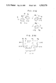
- FIG. 6(a) is a schematic perspective view showing a radiating section of a circular polarization antenna as a second embodiment of this invention
- FIG. 6(b) is a schematic representation of the circuit of a power supply section in the second embodiment
- FIG. 7 is a back view showing a circular polarization antenna as a third embodiment of the invention.
- FIG. 8(a) is a plan view showing an array antenna for dual polarization as a fourth embodiment of the invention.
- FIG. 8(b) is a schematic representation of the feed section used for the fourth embodiment of the antenna.
- FIG. 9 is a schematic view showing a feed line arrangement for a circular polarization antenna according to this invention.
- This invention relates to circular polarization antennas, which can transmit and receive excellent circular polarized waves over wide frequency band and have high polarization discrimination.
- This invention is based on the principle that perfectly circular polarized waves can be obtained by disposing a plurality of antenna elements at a constant orientation angle with respect to one another and feeding power to these antennas in a phase relationship corresponding to the orientation angle relationship.
- Electromagnetic waves radiated from each antenna element are generally elliptically polarized. If the polarization of electromagnetic waves radiated from a first antenna element as a reference antenna in the boresight direction is elliptical as shown in FIG. 1, the polarization vector E 1 can be expressed as
- n and n are at the angle ⁇ n with respect to the vectors 1 and 1 respectively.
- n and n are at the angle ⁇ n with respect to the vectors 1 and 1 respectively.
- FIG. 2 shows the degree of improvement of the cross polarization discrimination (XPD) obtained by the sequential structure over the unit element.
- f 0 represents the center frequency
- ⁇ f represents the frequency deviation from f 0 .
- FIGS. 3(a) and 3(b) show a first embodiment of the invention applied to a circular polarization antenna constructed as an N-element array antenna by disposing N (N ⁇ 3) antenna elements having the same polarization characteristics at arbitrary positions in a plane.
- each of N antenna elements 1-1, 1-2, . . . , 1-N is a patch antenna printed on the surface of a substrate, but it need not be a patch antenna.
- Each patch antenna element has a shape obtained by removing part of an ellipse. This is a measure for facilitating the recognition of the orientation of the antenna element, and this shape is by no means limitative and the antenna element may have any other desired shape such as a circular, square or elliptical shape.
- Feed points F 1 to F N of the respective antenna elements 1-1 to 1-N are disposed on a reference line R.
- the individual antenna elements 1-1 to 1-N are disposed with the orientation angle shifted by ⁇ /N (the n-th element is angled at (n-1) ⁇ /N in relation to the reference element) with respect to one another and are excited by respective phase shift of ⁇ /N with one another by corresponding feed lines 3-1, 3-2, . . . , 3-n, . . . , 3-N.
- a power divider 4 is adapted to distribute power such that a signal of a uniform amplitude is supplied to each element for excitation.
- FIGS. 4 and 5 show measurement data verifying this tendency.
- FIG. 4 shows axial ratio versus frequency
- FIG. 5 shows VSWR versus frequency.
- the sequential antenna constructed as a sample antenna is a 4-element array consisting of four back-side one-point excitation circular polarization patch antenna elements, with orientation angle and excitation phase shifted by ⁇ /4 with respect to one another.
- the figures also show comparative data on characteristics of a single antenna element and a conventional 4-element array consisting of two element-pairs. More particularly, curve I represents the characteristics of the single antenna element, curve II represents the characteristics of the conventional two-pair array antenna, and curve III represents the characteristics of the sequential array antenna according to this invention. It will be seen from FIG.
- a plurality of antenna elements are disposed in a spaced-apart positional relationship at arbitrary positions to construct a circular polarization antenna, but an equivalent circular polarization antenna can be constructed by disposing these antenna elements in one place as a unitary structure.
- FIGS. 6(a) and 6(b) show a second embodiment of the invention applied to a circular polarization antenna consisting of a plurality of antenna elements provided as a unitary structure. More specifically, a plurality of antenna elements are formed unitarily as a one-piece microstrip patch antenna 1 of a disc shape on a substrate 2. The patch antenna 1 is provided with respective distinct feed points F 1 to F 4 which are drawn out to the opposite surface of the substrate 2.
- FIG. 6(a) shows the patch antenna viewed from the side from which electromagnetic waves are radiated.
- FIG. 6(b) shows the circuit construction of a feed section for feeding power signals to the feed points.
- the feed points F 1 to F 4 are disposed such that they are symmetrical or have a definite periodicity with respect to the boresight axis. More specifically, they are disposed such that they are shifted by ⁇ /N (by ⁇ /4 rad. in this embodiment) with respect to the center O of the antenna from one another.
- the lengths of feed lines 3-1 to 3-4 are set such that the phases of excitation are shifted by ⁇ /N from one another in correspondence to the ⁇ /N rad. angularly rotational relationship to one another.
- this antenna radiates perfectly circularly polarized wave (left-hand circular polarization (LHCP) in this structure) in the boresight direction on the basis of the principles noted above irrespective of the polarization in the case of one-point feeding.
- this embodiment of the antenna is the same in construction, function and effect as the preceding embodiment, it can cover a far wider frequency range with respect to the axial ratio and impedance than the conventional one-point or two-point feeding single antenna.
- FIG. 7 shows a third embodiment of this invention, which is a modification of the foregoing first embodiment where each antenna element has a single feed point.
- This embodiment is applied to a circular polarization antenna of what is commonly termed a two-point structure with two feed points provided on seven antenna elements.
- the figure shows the feed circuit of the circular polarization array antenna viewed from the back side.
- Antenna elements 1-1 to 1-7 shown by dashed lines are formed on the flat front side of the substrate.
- Circular hybrid circuits H 1 to H 2 are provided on the back side of the substrate 2 in correspondence to the respective antenna elements 1-1 to 1-7. They have respective feed points F 1 to F 7 . Also, each of them have two connection points C spaced apart at an interval of 90 degrees.
- connection points C are connected by conductive leads through the substrate 2 to the opposite front side antenna elements 1-1 to 1-7.
- An input/output terminal 5 is connected to the feed points F 1 to F 7 of antenna elements by respective feed lines 3-1 to 3-7 which constitute a feed section.
- the wiring pattern of the feed lines 3-1 to 3-7 has no particular significance, but their length from the input/output terminal 5 to the feed point is important. More specifically, their length is progressively increased with respect to the feed line to the reference antenna element at such an interval that an input signal coupled to the input/output terminal 5 is fed to the individual antenna elements with progressively delayed phase at an interval of ⁇ /N corresponding to the frequency of the input signal.
- the width of the feed lines may be set suitably corresponding to the impedance of the feed lines.
- Reference numeral 6 in the figure designates a terminal resistor.
- a signal coupled to the input/output terminal 5 at the time of the transmission reaches the antenna elements 1-1 to 1-7 through the respective feed lines 3-1 to 3-7.
- the feed points F 1 to F 7 and connection points C of the individual antenna elements are in the angular relationship such that they are angularly spaced apart by ⁇ /N rad. with respect to those of the reference antenna element 1-1, the radiated electromagnetic wave is perfectly circularly polarized in the boresight direction.
- FIGS. 8(a) and 8(b) show a fourth embodiment of the circular polarization array antenna for the use of dual orthogonal polarizations.
- Antenna elements 1-1 to 1-N of the array antenna respectively include as integral components horn-type radiators 7-1 to 7-N, polarizers 8-1 to 8-N connected to the radiators and orthomode transducers (OMT) 9-1 to 9-N connected to the polarizers 8-1 to 8-N.
- OMT orthomode transducers
- a feed section f includes power branch circuits, i.e., power dividers in a transmitting system and power combiners in a receiving system (hereinafter referred to simply as power dividers) of right-hand circular polarization (RHCP) and left-hand circular polarization (LHCP), which have respective input/output terminals 5R and 5L, RHCP feed lines 3-1R to 3-NR leading from the RHCP power divider 4R to OMTs 9-1 to 9-N, and LHCP feed lines 3-1L to 3-NR leading from the LHCP power divider 4R to the OMTs 9-1 to 9-N.
- RHCP right-hand circular polarization
- LHCP left-hand circular polarization
- the RHCP and LHCP feed lines 3-1R to 3-NR and 3-1L to 3-NL are connected to the OMTs 9-1 to 9-N at respective feed points F-1R to F-NR and F-1L to F-NL.
- the RHCP and LHCP feed points F-nR and F-nL provided as a pair on the OMT of each antenna element are angularly shifted by 90 degrees.
- the orientation of the RHCP feed points F-1R to F-NR of the individual antenna elements (shown by line R in FIG. 8(a)) is angled at a constant angular interval ⁇ /N with respect to that of a reference antenna element.
- the RHCP feed point axis R of the antenna element 1-2 is shifted by ⁇ /N from that of the reference antenna element 1-1, and that of the n-th antenna element 1-n is shifted by (n-1) ⁇ /N from that of the reference antenna element.
- the feed lines are arranged such as to distribute power to the individual antenna elements in a phase relationship corresponding to the orientation angle relationship of their feed points as in the preceding embodiments. More specifically, the feed lines 3-1R to 3-NR from the RHCP power divider 4R are arranged such that the individual antenna elements are excited in progressively advanced phase relationship at an interval of ⁇ /N radians from the element 1-N toward the element 1-1. This means that the excitation phase is progressively advanced at an interval of ⁇ /N rad. from the side of the element 1-1. As for the feed lines from the LHCP power divider 4L, the excitation phase is progressively delayed by ⁇ /N rad. from the side of the antenna element 1-1.
- the arrangement of the feed lines as described is applicable where the orientation angle of the antenna elements is spaced apart in the clockwise direction, while the arrangement is reversed where the orientation angle is spaced apart counterclockwise.
- the feed lines must be arranged such that the feed points of the individual antenna elements are angularly spaced apart in orientation at an interval of ⁇ /N and the phase of excitation of the individual antenna elements is correspondingly shifted at an interval of ⁇ /N.
- the feed line pattern is designed by a trial-and-error method until the requirements noted above are met. This procedure, however, is quite troublesome.
- feed lines providing the relative phase shift of ⁇ n are designed such that their radius r is:
- FIG. 9 shows an embodiment of the invention applied to a 4-element sequential array structure.
- Back-side one-point feed circular polarization patch antenna elements 1-1 to 1-4 shown by dashed lines are printedly provided on the opposite side of a substrate, while the feed lines shown by solid lines are laid on the front side.
- the angular orientation of individual elements 1-1 to 1-4 is shifted at an interval of ⁇ /4 rad. with respect to the orientation of the element 1-1.
- Feed lines from an input/output terminal 5 to respective points P 1 to P 4 have an equal length, and also line segments from point Q 1 to feed point F 1 , . . . , from point Q 4 to point F 4 in the individual antenna elements also have an equal length.
Abstract
Description
E.sub.1 =a· .sub.1 +j·b· .sub.1 (1)
φ.sub.n =p(n-1)π/N(rad.) (2)
E.sub.n =(a· .sub.n +j·b· .sub.n)e.sup.j·φ n (3)
r=λg/2π (λg being the guide wavelength of the feed line)
Claims (5)
Applications Claiming Priority (2)
| Application Number | Priority Date | Filing Date | Title |
|---|---|---|---|
| JP58-51498 | 1983-03-29 | ||
| JP58051498A JPS59178002A (en) | 1983-03-29 | 1983-03-29 | Circularly polarized wave antenna |
Publications (1)
| Publication Number | Publication Date |
|---|---|
| US4543579A true US4543579A (en) | 1985-09-24 |
Family
ID=12888634
Family Applications (1)
| Application Number | Title | Priority Date | Filing Date |
|---|---|---|---|
| US06/550,120 Expired - Lifetime US4543579A (en) | 1983-03-29 | 1983-11-09 | Circular polarization antenna |
Country Status (2)
| Country | Link |
|---|---|
| US (1) | US4543579A (en) |
| JP (1) | JPS59178002A (en) |
Cited By (56)
| Publication number | Priority date | Publication date | Assignee | Title |
|---|---|---|---|---|
| US4649391A (en) * | 1984-02-01 | 1987-03-10 | Hughes Aircraft Company | Monopulse cavity-backed multipole antenna system |
| US4792810A (en) * | 1985-07-23 | 1988-12-20 | Sony Corporation | Microwave antenna |
| US4827276A (en) * | 1986-06-05 | 1989-05-02 | Sony Corporation | Microwave antenna |
| US4866451A (en) * | 1984-06-25 | 1989-09-12 | Communications Satellite Corporation | Broadband circular polarization arrangement for microstrip array antenna |
| EP0345454A1 (en) * | 1988-05-13 | 1989-12-13 | Yagi Antenna Co., Ltd. | Microstrip array antenna |
| US4973972A (en) * | 1989-09-07 | 1990-11-27 | The United States Of America As Represented By The Administrator Of The National Aeronautics And Space Adminstration | Stripline feed for a microstrip array of patch elements with teardrop shaped probes |
| US5014070A (en) * | 1987-07-10 | 1991-05-07 | Licentia Patent-Verwaltungs Gmbh | Radar camouflage material |
| EP0507307A2 (en) * | 1991-04-05 | 1992-10-07 | Ball Corporation | Broadband circular polarization satellite antenna |
| US5181042A (en) * | 1988-05-13 | 1993-01-19 | Yagi Antenna Co., Ltd. | Microstrip array antenna |
| US5398035A (en) * | 1992-11-30 | 1995-03-14 | The United States Of America As Represented By The Administrator Of The National Aeronautics And Space Administration | Satellite-tracking millimeter-wave reflector antenna system for mobile satellite-tracking |
| US5453752A (en) * | 1991-05-03 | 1995-09-26 | Georgia Tech Research Corporation | Compact broadband microstrip antenna |
| GB2308504A (en) * | 1995-12-20 | 1997-06-25 | Oceonics Group Plc | Phase compensation in a patch antenna |
| US5661494A (en) * | 1995-03-24 | 1997-08-26 | The United States Of America As Represented By The Administrator Of The National Aeronautics And Space Administration | High performance circularly polarized microstrip antenna |
| US5760741A (en) * | 1996-04-09 | 1998-06-02 | Trw Inc. | Beam forming network for multiple-beam-feed sharing antenna system |
| US6078287A (en) * | 1999-08-13 | 2000-06-20 | Hughes Electronics Corporation | Beam forming network incorporating phase compensation |
| US6288677B1 (en) | 1999-11-23 | 2001-09-11 | The United States Of America As Represented By The Administrator Of The National Aeronautics And Space Administration | Microstrip patch antenna and method |
| US6292133B1 (en) | 1999-07-26 | 2001-09-18 | Harris Corporation | Array antenna with selectable scan angles |
| EP1168492A1 (en) * | 2000-06-27 | 2002-01-02 | Toko, Inc. | A plane antenna |
| US6388621B1 (en) | 2000-06-20 | 2002-05-14 | Harris Corporation | Optically transparent phase array antenna |
| US20050099358A1 (en) * | 2002-11-08 | 2005-05-12 | Kvh Industries, Inc. | Feed network and method for an offset stacked patch antenna array |
| US20060170596A1 (en) * | 2004-03-15 | 2006-08-03 | Elta Systems Ltd. | High gain antenna for microwave frequencies |
| US20070273531A1 (en) * | 2006-05-23 | 2007-11-29 | Koji Ando | Communication antenna and pole with built-in antenna |
| WO2008060674A2 (en) * | 2006-06-19 | 2008-05-22 | General Electric Company | Radio detection and ranging intrusion detection system |
| US20090046026A1 (en) * | 2006-02-14 | 2009-02-19 | Hisamatsu Nakano | Circularly polarized antenna |
| EP2148390A1 (en) * | 2007-05-17 | 2010-01-27 | Omron Corporation | Array antenna |
| US20110025573A1 (en) * | 2009-08-03 | 2011-02-03 | William Ernest Payne | Cross-dipole antenna |
| US20110025569A1 (en) * | 2009-08-03 | 2011-02-03 | Venti Group, LLC | Cross-dipole antenna combination |
| US20110068992A1 (en) * | 2009-08-03 | 2011-03-24 | Venti Group, LLC | Cross-dipole antenna configurations |
| US8624791B2 (en) | 2012-03-22 | 2014-01-07 | Venti Group, LLC | Chokes for electrical cables |
| US8803755B2 (en) | 2013-01-10 | 2014-08-12 | Venti Group, LLC | Low passive intermodulation chokes for electrical cables |
| US20150002335A1 (en) * | 2013-06-28 | 2015-01-01 | Mimosa Networks, Inc. | Ellipticity reduction in circularly polarized array antennas |
| US9391375B1 (en) | 2013-09-27 | 2016-07-12 | The United States Of America As Represented By The Secretary Of The Navy | Wideband planar reconfigurable polarization antenna array |
| GB2540800A (en) * | 2015-07-28 | 2017-02-01 | Guidance Marine Ltd | Antenna Array |
| US9693388B2 (en) | 2013-05-30 | 2017-06-27 | Mimosa Networks, Inc. | Wireless access points providing hybrid 802.11 and scheduled priority access communications |
| US9780892B2 (en) | 2014-03-05 | 2017-10-03 | Mimosa Networks, Inc. | System and method for aligning a radio using an automated audio guide |
| US9843940B2 (en) | 2013-03-08 | 2017-12-12 | Mimosa Networks, Inc. | System and method for dual-band backhaul radio |
| US9871302B2 (en) | 2013-03-06 | 2018-01-16 | Mimosa Networks, Inc. | Enclosure for radio, parabolic dish antenna, and side lobe shields |
| US9888485B2 (en) | 2014-01-24 | 2018-02-06 | Mimosa Networks, Inc. | Channel optimization in half duplex communications systems |
| US9930592B2 (en) | 2013-02-19 | 2018-03-27 | Mimosa Networks, Inc. | Systems and methods for directing mobile device connectivity |
| US9985363B2 (en) | 2013-10-18 | 2018-05-29 | Venti Group, LLC | Electrical connectors with low passive intermodulation |
| US9986565B2 (en) | 2013-02-19 | 2018-05-29 | Mimosa Networks, Inc. | WiFi management interface for microwave radio and reset to factory defaults |
| US9998246B2 (en) | 2014-03-13 | 2018-06-12 | Mimosa Networks, Inc. | Simultaneous transmission on shared channel |
| US10096933B2 (en) | 2013-03-06 | 2018-10-09 | Mimosa Networks, Inc. | Waterproof apparatus for cables and cable interfaces |
| US10511074B2 (en) | 2018-01-05 | 2019-12-17 | Mimosa Networks, Inc. | Higher signal isolation solutions for printed circuit board mounted antenna and waveguide interface |
| US10742275B2 (en) | 2013-03-07 | 2020-08-11 | Mimosa Networks, Inc. | Quad-sector antenna using circular polarization |
| US10749263B2 (en) | 2016-01-11 | 2020-08-18 | Mimosa Networks, Inc. | Printed circuit board mounted antenna and waveguide interface |
| RU2738350C1 (en) * | 2019-11-22 | 2020-12-11 | Федеральное государственное бюджетное образовательное учреждение высшего образования "Московский автомобильно-дорожный государственный технический университет (МАДИ) | Digital information wireless transmission method |
| US10958332B2 (en) | 2014-09-08 | 2021-03-23 | Mimosa Networks, Inc. | Wi-Fi hotspot repeater |
| US11069986B2 (en) | 2018-03-02 | 2021-07-20 | Airspan Ip Holdco Llc | Omni-directional orthogonally-polarized antenna system for MIMO applications |
| US11233340B2 (en) | 2019-09-02 | 2022-01-25 | Nokia Solutions And Networks Oy | Polarized antenna array |
| US20220034961A1 (en) * | 2020-07-29 | 2022-02-03 | Rohde & Schwarz Gmbh & Co. Kg | Antenna assembly, test system and method of establishing a test system |
| US11251539B2 (en) | 2016-07-29 | 2022-02-15 | Airspan Ip Holdco Llc | Multi-band access point antenna array |
| US11264732B2 (en) * | 2017-04-26 | 2022-03-01 | Murata Manufacturing Co., Ltd. | Antenna module and communication apparatus |
| WO2022055544A1 (en) * | 2020-09-08 | 2022-03-17 | Raytheon Company | Multi-beam passively-switched patch antenna array |
| US11289821B2 (en) | 2018-09-11 | 2022-03-29 | Air Span Ip Holdco Llc | Sector antenna systems and methods for providing high gain and high side-lobe rejection |
| US11695218B2 (en) | 2020-05-11 | 2023-07-04 | Nokia Solutions And Networks Oy | Antenna arrangement |
Families Citing this family (4)
| Publication number | Priority date | Publication date | Assignee | Title |
|---|---|---|---|---|
| JPH0770904B2 (en) * | 1984-12-26 | 1995-07-31 | 株式会社東芝 | Circularly polarized array antenna |
| JPH0625051Y2 (en) * | 1987-03-09 | 1994-06-29 | 株式会社東芝 | Microwave antenna device |
| JPH04207602A (en) * | 1990-11-30 | 1992-07-29 | Dx Antenna Co Ltd | Circularly/linearly polarized wave converter |
| JPH06169219A (en) * | 1991-05-27 | 1994-06-14 | Yuseisho Tsushin Sogo Kenkyusho | Multi-point feeding circularly polarized wave antenna |
Citations (4)
| Publication number | Priority date | Publication date | Assignee | Title |
|---|---|---|---|---|
| JPS56160103A (en) * | 1980-05-14 | 1981-12-09 | Toshiba Corp | Microstrip-type antenna |
| US4318107A (en) * | 1978-11-24 | 1982-03-02 | Thomson-Csf | Printed monopulse primary source for airport radar antenna and antenna comprising such a source |
| US4345255A (en) * | 1978-12-25 | 1982-08-17 | Kokusai Denshin Denwa Co., Ltd. | Antenna feed system |
| JPS5859606A (en) * | 1981-10-05 | 1983-04-08 | Toshiba Corp | Microstrip antenna |
Family Cites Families (2)
| Publication number | Priority date | Publication date | Assignee | Title |
|---|---|---|---|---|
| JPS5839401B2 (en) * | 1976-07-13 | 1983-08-30 | 三菱電機株式会社 | circular array antenna |
| JPS55107305A (en) * | 1979-02-13 | 1980-08-18 | Mitsubishi Electric Corp | Microstrip antenna |
-
1983
- 1983-03-29 JP JP58051498A patent/JPS59178002A/en active Pending
- 1983-11-09 US US06/550,120 patent/US4543579A/en not_active Expired - Lifetime
Patent Citations (4)
| Publication number | Priority date | Publication date | Assignee | Title |
|---|---|---|---|---|
| US4318107A (en) * | 1978-11-24 | 1982-03-02 | Thomson-Csf | Printed monopulse primary source for airport radar antenna and antenna comprising such a source |
| US4345255A (en) * | 1978-12-25 | 1982-08-17 | Kokusai Denshin Denwa Co., Ltd. | Antenna feed system |
| JPS56160103A (en) * | 1980-05-14 | 1981-12-09 | Toshiba Corp | Microstrip-type antenna |
| JPS5859606A (en) * | 1981-10-05 | 1983-04-08 | Toshiba Corp | Microstrip antenna |
Cited By (94)
| Publication number | Priority date | Publication date | Assignee | Title |
|---|---|---|---|---|
| US4649391A (en) * | 1984-02-01 | 1987-03-10 | Hughes Aircraft Company | Monopulse cavity-backed multipole antenna system |
| US4866451A (en) * | 1984-06-25 | 1989-09-12 | Communications Satellite Corporation | Broadband circular polarization arrangement for microstrip array antenna |
| US4792810A (en) * | 1985-07-23 | 1988-12-20 | Sony Corporation | Microwave antenna |
| US4827276A (en) * | 1986-06-05 | 1989-05-02 | Sony Corporation | Microwave antenna |
| US5014070A (en) * | 1987-07-10 | 1991-05-07 | Licentia Patent-Verwaltungs Gmbh | Radar camouflage material |
| US5181042A (en) * | 1988-05-13 | 1993-01-19 | Yagi Antenna Co., Ltd. | Microstrip array antenna |
| EP0345454A1 (en) * | 1988-05-13 | 1989-12-13 | Yagi Antenna Co., Ltd. | Microstrip array antenna |
| US4973972A (en) * | 1989-09-07 | 1990-11-27 | The United States Of America As Represented By The Administrator Of The National Aeronautics And Space Adminstration | Stripline feed for a microstrip array of patch elements with teardrop shaped probes |
| EP0507307A2 (en) * | 1991-04-05 | 1992-10-07 | Ball Corporation | Broadband circular polarization satellite antenna |
| US5231406A (en) * | 1991-04-05 | 1993-07-27 | Ball Corporation | Broadband circular polarization satellite antenna |
| EP0507307A3 (en) * | 1991-04-05 | 1994-09-28 | Ball Corp | Broadband circular polarization satellite antenna |
| US5453752A (en) * | 1991-05-03 | 1995-09-26 | Georgia Tech Research Corporation | Compact broadband microstrip antenna |
| USRE37218E1 (en) | 1992-11-30 | 2001-06-12 | The United States Of America As Represented By The Administrator Of The National Aeronautics And Space Administration | Satellite-tracking millimeter-wave reflector antenna system for mobile satellite-tracking |
| US5398035A (en) * | 1992-11-30 | 1995-03-14 | The United States Of America As Represented By The Administrator Of The National Aeronautics And Space Administration | Satellite-tracking millimeter-wave reflector antenna system for mobile satellite-tracking |
| US5661494A (en) * | 1995-03-24 | 1997-08-26 | The United States Of America As Represented By The Administrator Of The National Aeronautics And Space Administration | High performance circularly polarized microstrip antenna |
| GB2308504A (en) * | 1995-12-20 | 1997-06-25 | Oceonics Group Plc | Phase compensation in a patch antenna |
| US5760741A (en) * | 1996-04-09 | 1998-06-02 | Trw Inc. | Beam forming network for multiple-beam-feed sharing antenna system |
| US6292133B1 (en) | 1999-07-26 | 2001-09-18 | Harris Corporation | Array antenna with selectable scan angles |
| US6078287A (en) * | 1999-08-13 | 2000-06-20 | Hughes Electronics Corporation | Beam forming network incorporating phase compensation |
| US6288677B1 (en) | 1999-11-23 | 2001-09-11 | The United States Of America As Represented By The Administrator Of The National Aeronautics And Space Administration | Microstrip patch antenna and method |
| US6388621B1 (en) | 2000-06-20 | 2002-05-14 | Harris Corporation | Optically transparent phase array antenna |
| EP1168492A1 (en) * | 2000-06-27 | 2002-01-02 | Toko, Inc. | A plane antenna |
| US6407707B2 (en) | 2000-06-27 | 2002-06-18 | Toko, Inc. | Plane antenna |
| US20050099358A1 (en) * | 2002-11-08 | 2005-05-12 | Kvh Industries, Inc. | Feed network and method for an offset stacked patch antenna array |
| US20060170596A1 (en) * | 2004-03-15 | 2006-08-03 | Elta Systems Ltd. | High gain antenna for microwave frequencies |
| US8228235B2 (en) * | 2004-03-15 | 2012-07-24 | Elta Systems Ltd. | High gain antenna for microwave frequencies |
| US20090046026A1 (en) * | 2006-02-14 | 2009-02-19 | Hisamatsu Nakano | Circularly polarized antenna |
| US20070273531A1 (en) * | 2006-05-23 | 2007-11-29 | Koji Ando | Communication antenna and pole with built-in antenna |
| WO2008060674A2 (en) * | 2006-06-19 | 2008-05-22 | General Electric Company | Radio detection and ranging intrusion detection system |
| WO2008060674A3 (en) * | 2006-06-19 | 2008-07-24 | Gen Electric | Radio detection and ranging intrusion detection system |
| US20100171665A1 (en) * | 2007-05-17 | 2010-07-08 | Omron Corporation | Array antenna |
| EP2148390A1 (en) * | 2007-05-17 | 2010-01-27 | Omron Corporation | Array antenna |
| EP2148390A4 (en) * | 2007-05-17 | 2014-01-08 | Omron Tateisi Electronics Co | Array antenna |
| US8289214B2 (en) * | 2007-05-17 | 2012-10-16 | Omron Corporation | Array antenna |
| US20110025573A1 (en) * | 2009-08-03 | 2011-02-03 | William Ernest Payne | Cross-dipole antenna |
| US20110068992A1 (en) * | 2009-08-03 | 2011-03-24 | Venti Group, LLC | Cross-dipole antenna configurations |
| US8289218B2 (en) | 2009-08-03 | 2012-10-16 | Venti Group, LLC | Cross-dipole antenna combination |
| US8325101B2 (en) | 2009-08-03 | 2012-12-04 | Venti Group, LLC | Cross-dipole antenna configurations |
| US8427385B2 (en) | 2009-08-03 | 2013-04-23 | Venti Group, LLC | Cross-dipole antenna |
| US20110025569A1 (en) * | 2009-08-03 | 2011-02-03 | Venti Group, LLC | Cross-dipole antenna combination |
| US8638270B2 (en) | 2009-08-03 | 2014-01-28 | Venti Group, LLC | Cross-dipole antenna configurations |
| US9710576B2 (en) | 2009-08-03 | 2017-07-18 | Venti Group, LLC | Cross-dipole antenna configurations |
| US8624791B2 (en) | 2012-03-22 | 2014-01-07 | Venti Group, LLC | Chokes for electrical cables |
| US8803755B2 (en) | 2013-01-10 | 2014-08-12 | Venti Group, LLC | Low passive intermodulation chokes for electrical cables |
| US9930592B2 (en) | 2013-02-19 | 2018-03-27 | Mimosa Networks, Inc. | Systems and methods for directing mobile device connectivity |
| US10425944B2 (en) | 2013-02-19 | 2019-09-24 | Mimosa Networks, Inc. | WiFi management interface for microwave radio and reset to factory defaults |
| US10200925B2 (en) | 2013-02-19 | 2019-02-05 | Mimosa Networks, Inc. | Systems and methods for directing mobile device connectivity |
| US10863507B2 (en) | 2013-02-19 | 2020-12-08 | Mimosa Networks, Inc. | WiFi management interface for microwave radio and reset to factory defaults |
| US9986565B2 (en) | 2013-02-19 | 2018-05-29 | Mimosa Networks, Inc. | WiFi management interface for microwave radio and reset to factory defaults |
| US10595253B2 (en) | 2013-02-19 | 2020-03-17 | Mimosa Networks, Inc. | Systems and methods for directing mobile device connectivity |
| US9871302B2 (en) | 2013-03-06 | 2018-01-16 | Mimosa Networks, Inc. | Enclosure for radio, parabolic dish antenna, and side lobe shields |
| US10186786B2 (en) | 2013-03-06 | 2019-01-22 | Mimosa Networks, Inc. | Enclosure for radio, parabolic dish antenna, and side lobe shields |
| US10790613B2 (en) | 2013-03-06 | 2020-09-29 | Mimosa Networks, Inc. | Waterproof apparatus for pre-terminated cables |
| US10096933B2 (en) | 2013-03-06 | 2018-10-09 | Mimosa Networks, Inc. | Waterproof apparatus for cables and cable interfaces |
| US10742275B2 (en) | 2013-03-07 | 2020-08-11 | Mimosa Networks, Inc. | Quad-sector antenna using circular polarization |
| US9843940B2 (en) | 2013-03-08 | 2017-12-12 | Mimosa Networks, Inc. | System and method for dual-band backhaul radio |
| US9949147B2 (en) | 2013-03-08 | 2018-04-17 | Mimosa Networks, Inc. | System and method for dual-band backhaul radio |
| US10257722B2 (en) | 2013-03-08 | 2019-04-09 | Mimosa Networks, Inc. | System and method for dual-band backhaul radio |
| US10812994B2 (en) | 2013-03-08 | 2020-10-20 | Mimosa Networks, Inc. | System and method for dual-band backhaul radio |
| US10117114B2 (en) | 2013-03-08 | 2018-10-30 | Mimosa Networks, Inc. | System and method for dual-band backhaul radio |
| US9693388B2 (en) | 2013-05-30 | 2017-06-27 | Mimosa Networks, Inc. | Wireless access points providing hybrid 802.11 and scheduled priority access communications |
| US10785608B2 (en) | 2013-05-30 | 2020-09-22 | Mimosa Networks, Inc. | Wireless access points providing hybrid 802.11 and scheduled priority access communications |
| US20150002335A1 (en) * | 2013-06-28 | 2015-01-01 | Mimosa Networks, Inc. | Ellipticity reduction in circularly polarized array antennas |
| US11482789B2 (en) | 2013-06-28 | 2022-10-25 | Airspan Ip Holdco Llc | Ellipticity reduction in circularly polarized array antennas |
| US10938110B2 (en) * | 2013-06-28 | 2021-03-02 | Mimosa Networks, Inc. | Ellipticity reduction in circularly polarized array antennas |
| US9391375B1 (en) | 2013-09-27 | 2016-07-12 | The United States Of America As Represented By The Secretary Of The Navy | Wideband planar reconfigurable polarization antenna array |
| US9985363B2 (en) | 2013-10-18 | 2018-05-29 | Venti Group, LLC | Electrical connectors with low passive intermodulation |
| US9888485B2 (en) | 2014-01-24 | 2018-02-06 | Mimosa Networks, Inc. | Channel optimization in half duplex communications systems |
| US10616903B2 (en) | 2014-01-24 | 2020-04-07 | Mimosa Networks, Inc. | Channel optimization in half duplex communications systems |
| US10090943B2 (en) | 2014-03-05 | 2018-10-02 | Mimosa Networks, Inc. | System and method for aligning a radio using an automated audio guide |
| US9780892B2 (en) | 2014-03-05 | 2017-10-03 | Mimosa Networks, Inc. | System and method for aligning a radio using an automated audio guide |
| US11888589B2 (en) | 2014-03-13 | 2024-01-30 | Mimosa Networks, Inc. | Synchronized transmission on shared channel |
| US10447417B2 (en) | 2014-03-13 | 2019-10-15 | Mimosa Networks, Inc. | Synchronized transmission on shared channel |
| US9998246B2 (en) | 2014-03-13 | 2018-06-12 | Mimosa Networks, Inc. | Simultaneous transmission on shared channel |
| US11626921B2 (en) | 2014-09-08 | 2023-04-11 | Airspan Ip Holdco Llc | Systems and methods of a Wi-Fi repeater device |
| US10958332B2 (en) | 2014-09-08 | 2021-03-23 | Mimosa Networks, Inc. | Wi-Fi hotspot repeater |
| GB2540800A (en) * | 2015-07-28 | 2017-02-01 | Guidance Marine Ltd | Antenna Array |
| GB2540800B (en) * | 2015-07-28 | 2019-09-11 | Guidance Marine Ltd | Antenna Array for Producing Beam Patterns Requiring a Large Phase Shift |
| US10749263B2 (en) | 2016-01-11 | 2020-08-18 | Mimosa Networks, Inc. | Printed circuit board mounted antenna and waveguide interface |
| US11251539B2 (en) | 2016-07-29 | 2022-02-15 | Airspan Ip Holdco Llc | Multi-band access point antenna array |
| US11264732B2 (en) * | 2017-04-26 | 2022-03-01 | Murata Manufacturing Co., Ltd. | Antenna module and communication apparatus |
| US10714805B2 (en) | 2018-01-05 | 2020-07-14 | Milmosa Networks, Inc. | Higher signal isolation solutions for printed circuit board mounted antenna and waveguide interface |
| US10511074B2 (en) | 2018-01-05 | 2019-12-17 | Mimosa Networks, Inc. | Higher signal isolation solutions for printed circuit board mounted antenna and waveguide interface |
| US11404796B2 (en) | 2018-03-02 | 2022-08-02 | Airspan Ip Holdco Llc | Omni-directional orthogonally-polarized antenna system for MIMO applications |
| US11069986B2 (en) | 2018-03-02 | 2021-07-20 | Airspan Ip Holdco Llc | Omni-directional orthogonally-polarized antenna system for MIMO applications |
| US11637384B2 (en) | 2018-03-02 | 2023-04-25 | Airspan Ip Holdco Llc | Omni-directional antenna system and device for MIMO applications |
| US11289821B2 (en) | 2018-09-11 | 2022-03-29 | Air Span Ip Holdco Llc | Sector antenna systems and methods for providing high gain and high side-lobe rejection |
| US11233340B2 (en) | 2019-09-02 | 2022-01-25 | Nokia Solutions And Networks Oy | Polarized antenna array |
| RU2738350C1 (en) * | 2019-11-22 | 2020-12-11 | Федеральное государственное бюджетное образовательное учреждение высшего образования "Московский автомобильно-дорожный государственный технический университет (МАДИ) | Digital information wireless transmission method |
| US11695218B2 (en) | 2020-05-11 | 2023-07-04 | Nokia Solutions And Networks Oy | Antenna arrangement |
| US20220034961A1 (en) * | 2020-07-29 | 2022-02-03 | Rohde & Schwarz Gmbh & Co. Kg | Antenna assembly, test system and method of establishing a test system |
| US11789068B2 (en) * | 2020-07-29 | 2023-10-17 | Rohde & Schwarz Gmbh & Co. Kg | Antenna assembly, test system and method of establishing a test system |
| WO2022055544A1 (en) * | 2020-09-08 | 2022-03-17 | Raytheon Company | Multi-beam passively-switched patch antenna array |
| US11929556B2 (en) | 2020-09-08 | 2024-03-12 | Raytheon Company | Multi-beam passively-switched patch antenna array |
Also Published As
| Publication number | Publication date |
|---|---|
| JPS59178002A (en) | 1984-10-09 |
Similar Documents
| Publication | Publication Date | Title |
|---|---|---|
| US4543579A (en) | Circular polarization antenna | |
| US5675345A (en) | Compact antenna with folded substrate | |
| US4208660A (en) | Radio frequency ring-shaped slot antenna | |
| Huang et al. | A Ka-band microstrip reflectarray with elements having variable rotation angles | |
| US6147648A (en) | Dual polarization antenna array with very low cross polarization and low side lobes | |
| Kaiser | The Archimedean two-wire spiral antenna | |
| US5359338A (en) | Linear conformal antenna array for scanning near end-fire in one direction | |
| US7990327B2 (en) | Cellular reflectarray antenna and method of making same | |
| US7209080B2 (en) | Multiple-port patch antenna | |
| US5786793A (en) | Compact antenna for circular polarization | |
| US4320402A (en) | Multiple ring microstrip antenna | |
| US6288677B1 (en) | Microstrip patch antenna and method | |
| US6466177B1 (en) | Controlled radiation pattern array antenna using spiral slot array elements | |
| EP0001883B1 (en) | Apparatus for improving r.f. isolation between adjacent microstrip antenna arrays | |
| US6087988A (en) | In-line CP patch radiator | |
| GB2251340A (en) | Antenna | |
| Cao et al. | A pillbox based dual circularly-polarized millimeter-wave multi-beam antenna for future vehicular radar applications | |
| US20020018018A1 (en) | Planar polarizer feed network for a dual circular polarized antenna array | |
| US3977006A (en) | Compensated traveling wave slotted waveguide feed for cophasal arrays | |
| JP2578711B2 (en) | Low sidelobe antenna device | |
| US10931024B2 (en) | Linear-to-CP polarizer with enhanced performance in VICTS antennas | |
| US4584582A (en) | Multi-mode direction finding antenna | |
| JPH046125B2 (en) | ||
| US11539146B2 (en) | Circular polarized phased array with wideband axial ratio bandwidth using sequential rotation and dynamic phase recovery | |
| JP3468044B2 (en) | Planar antenna |
Legal Events
| Date | Code | Title | Description |
|---|---|---|---|
| AS | Assignment |
Owner name: RADIO RESEARCH LABORATORIES, MINISTRY OF POSTS AND Free format text: ASSIGNMENT OF ASSIGNORS INTEREST.;ASSIGNOR:TESHIROGI, TASUKU;REEL/FRAME:004419/0441 Effective date: 19831101 Owner name: RADIO RESEARCH LABORATORIES, MINISTRY OF POSTS AND Free format text: ASSIGNMENT OF ASSIGNORS INTEREST;ASSIGNOR:TESHIROGI, TASUKU;REEL/FRAME:004419/0441 Effective date: 19831101 |
|
| STCF | Information on status: patent grant |
Free format text: PATENTED CASE |
|
| FEPP | Fee payment procedure |
Free format text: PAYOR NUMBER ASSIGNED (ORIGINAL EVENT CODE: ASPN); ENTITY STATUS OF PATENT OWNER: LARGE ENTITY |
|
| FPAY | Fee payment |
Year of fee payment: 4 |
|
| FPAY | Fee payment |
Year of fee payment: 8 |
|
| FPAY | Fee payment |
Year of fee payment: 12 |
|
| AS | Assignment |
Owner name: COMMUNICATIONS RESEARCH LABORATORY, INDEPENDENT AD Free format text: RESTRUCTURING OF GOVERNMENTAL AGENCIES OF JAPAN;ASSIGNOR:COMMUNICATIONS RESEARCH LABORATORY, MINISTRY OF POSTS AND TELECOMMUNICATIONS;REEL/FRAME:012475/0704 Effective date: 20010106 Owner name: COMMUNICATIONS RESEARCH LABORATORY, INDEPENDENT AD Free format text: ESTABLISHMENT OF INDEPENDENT ADMINISTRATIVE INSTITUTION BY JAPANESE GOVERNMENT SUCCESSIVE TO GOVERNMENTAL AGENCY.;ASSIGNOR:COMMUNICATIONS RESEARCH LABORATORY, INDEPENDENT ADMINISTRATIVE INSTITUTION;REEL/FRAME:012495/0056 Effective date: 20010401 |