US4535929A - Reusable shipping box with cam tabs for release of closure interlock - Google Patents
Reusable shipping box with cam tabs for release of closure interlock Download PDFInfo
- Publication number
- US4535929A US4535929A US06/533,434 US53343483A US4535929A US 4535929 A US4535929 A US 4535929A US 53343483 A US53343483 A US 53343483A US 4535929 A US4535929 A US 4535929A
- Authority
- US
- United States
- Prior art keywords
- panel
- locking
- flap
- locking slot
- secured
- Prior art date
- Legal status (The legal status is an assumption and is not a legal conclusion. Google has not performed a legal analysis and makes no representation as to the accuracy of the status listed.)
- Expired - Fee Related
Links
Images

Classifications
-
- B—PERFORMING OPERATIONS; TRANSPORTING
- B65—CONVEYING; PACKING; STORING; HANDLING THIN OR FILAMENTARY MATERIAL
- B65D—CONTAINERS FOR STORAGE OR TRANSPORT OF ARTICLES OR MATERIALS, e.g. BAGS, BARRELS, BOTTLES, BOXES, CANS, CARTONS, CRATES, DRUMS, JARS, TANKS, HOPPERS, FORWARDING CONTAINERS; ACCESSORIES, CLOSURES, OR FITTINGS THEREFOR; PACKAGING ELEMENTS; PACKAGES
- B65D5/00—Rigid or semi-rigid containers of polygonal cross-section, e.g. boxes, cartons or trays, formed by folding or erecting one or more blanks made of paper
- B65D5/02—Rigid or semi-rigid containers of polygonal cross-section, e.g. boxes, cartons or trays, formed by folding or erecting one or more blanks made of paper by folding or erecting a single blank to form a tubular body with or without subsequent folding operations, or the addition of separate elements, to close the ends of the body
- B65D5/10—Rigid or semi-rigid containers of polygonal cross-section, e.g. boxes, cartons or trays, formed by folding or erecting one or more blanks made of paper by folding or erecting a single blank to form a tubular body with or without subsequent folding operations, or the addition of separate elements, to close the ends of the body with end closures formed by inward-folding of self-locking flaps hinged to tubular body
- B65D5/103—Rigid or semi-rigid containers of polygonal cross-section, e.g. boxes, cartons or trays, formed by folding or erecting one or more blanks made of paper by folding or erecting a single blank to form a tubular body with or without subsequent folding operations, or the addition of separate elements, to close the ends of the body with end closures formed by inward-folding of self-locking flaps hinged to tubular body one of the self-locking flaps having a tongue engaging into an opening of an opposite flap
-
- Y—GENERAL TAGGING OF NEW TECHNOLOGICAL DEVELOPMENTS; GENERAL TAGGING OF CROSS-SECTIONAL TECHNOLOGIES SPANNING OVER SEVERAL SECTIONS OF THE IPC; TECHNICAL SUBJECTS COVERED BY FORMER USPC CROSS-REFERENCE ART COLLECTIONS [XRACs] AND DIGESTS
- Y02—TECHNOLOGIES OR APPLICATIONS FOR MITIGATION OR ADAPTATION AGAINST CLIMATE CHANGE
- Y02W—CLIMATE CHANGE MITIGATION TECHNOLOGIES RELATED TO WASTEWATER TREATMENT OR WASTE MANAGEMENT
- Y02W30/00—Technologies for solid waste management
- Y02W30/50—Reuse, recycling or recovery technologies
- Y02W30/80—Packaging reuse or recycling, e.g. of multilayer packaging
-
- Y—GENERAL TAGGING OF NEW TECHNOLOGICAL DEVELOPMENTS; GENERAL TAGGING OF CROSS-SECTIONAL TECHNOLOGIES SPANNING OVER SEVERAL SECTIONS OF THE IPC; TECHNICAL SUBJECTS COVERED BY FORMER USPC CROSS-REFERENCE ART COLLECTIONS [XRACs] AND DIGESTS
- Y10—TECHNICAL SUBJECTS COVERED BY FORMER USPC
- Y10S—TECHNICAL SUBJECTS COVERED BY FORMER USPC CROSS-REFERENCE ART COLLECTIONS [XRACs] AND DIGESTS
- Y10S206/00—Special receptacle or package
- Y10S206/807—Tamper proof
-
- Y—GENERAL TAGGING OF NEW TECHNOLOGICAL DEVELOPMENTS; GENERAL TAGGING OF CROSS-SECTIONAL TECHNOLOGIES SPANNING OVER SEVERAL SECTIONS OF THE IPC; TECHNICAL SUBJECTS COVERED BY FORMER USPC CROSS-REFERENCE ART COLLECTIONS [XRACs] AND DIGESTS
- Y10—TECHNICAL SUBJECTS COVERED BY FORMER USPC
- Y10S—TECHNICAL SUBJECTS COVERED BY FORMER USPC CROSS-REFERENCE ART COLLECTIONS [XRACs] AND DIGESTS
- Y10S206/00—Special receptacle or package
- Y10S206/815—Finger opening
-
- Y—GENERAL TAGGING OF NEW TECHNOLOGICAL DEVELOPMENTS; GENERAL TAGGING OF CROSS-SECTIONAL TECHNOLOGIES SPANNING OVER SEVERAL SECTIONS OF THE IPC; TECHNICAL SUBJECTS COVERED BY FORMER USPC CROSS-REFERENCE ART COLLECTIONS [XRACs] AND DIGESTS
- Y10—TECHNICAL SUBJECTS COVERED BY FORMER USPC
- Y10S—TECHNICAL SUBJECTS COVERED BY FORMER USPC CROSS-REFERENCE ART COLLECTIONS [XRACs] AND DIGESTS
- Y10S229/00—Envelopes, wrappers, and paperboard boxes
- Y10S229/921—Envelopes, wrappers, and paperboard boxes with mailing indicia
Definitions
- This invention relates to boxes, and, more particularly, to boxes preferably made of corrugated type material and which may be reusable for two-way shipping purposes.
- Containers for two-way shipping purposes have generally been made of corrugated cardboard or other types of relatively sturdy material.
- prior art containers have only a single top or lid flap.
- Such top or lid flap requires a new shipping label each time the container is shipped to a separate destination.
- some appropriate type of fastener such as staples, adhesives, or tape, is required to secure the top flap to the container for shipping purposes.
- the prior art containers usually include some type of fastening element for fastening the side panels or side flaps together.
- fastening elements may include staples, adhesives, or tape or the like.
- interlocking flaps At the bottom of containers, particularly containers made of corrugated or fluted type material, interlocking flaps have been used for a number of years. Such interconnecting and interlocking flaps do not require tape or other fastening elements. However, such is not the case with the securing of the sides together. As indicated above, tape, staples, or adhesives, or other elements are generally required to secure the sides together.
- a container has been developed with dual top flaps for two-way shipment.
- a co-inventor hereof is also co-inventor of the dual top flap apparatus, and such is employed herein.
- An advantage of the use of dual flaps is that the flaps may be pre-printed so that one flap indicates the destination for one direction and the other flap indicates the destination for shipment in the opposite or return direction.
- the pre-printed flaps are alternately used and thus the requirement of separate shipping labels is obviated.
- the invention described and claimed herein comprises a box made of a single blank of material.
- the blank includes a plurality of sides, flaps, tabs, and slots which are interlocking and which cooperate to define, when assembled, a box or container that is unitary in that no extra elements, such as staples, adhesive, or tape, are required to secure the box together since the interlocking tabs and angled slots cooperate to lock the various sides and flaps of the box together.
- the slots and tabs include cam elements which allow tabs to be aligned with the slots for the easy release of locking wing tabs to allow the top flaps to be unlocked. The unlocking of the top flaps allows the box apparatus to be opened for loading and unloading, or opening and closing, purposes.
- cam tabs for aligning locking wing tabs with slots for the release of flap elements.
- FIG. 1 is a plan view of the blank from which box apparatus of the present invention is formed.
- FIG. 2 is a perspective view of assembled box apparatus of the present invention.
- FIG. 3 is a perspective view of the apparatus of FIG. 2 with top flaps folded differently.
- FIG. 4 is a perspective view illustrating the unlocking of top flaps of the apparatus of the present invention.
- FIG. 5 is a perspective view of the blank of FIG. 1 illustrating the folding of the blank to assemble the box apparatus illustrated in FIGS. 2, 3, and 4.
- FIG. 6 is a perspective view of the blank of FIG. 1, illustrating an assembly step for the box apparatus of the present invention.
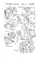
- FIG. 7 is a perspective view illustrating another assembly step for the fabrication of the box apparatus of the present invention.
- FIG. 8 is a perspective view illustrating another assembly step sequentially following the step shown in FIG. 7.
- FIG. 9 is a perspective view illustrating another assembly step sequentially following the step illustrated in FIG. 8.
- FIG. 10 is a perspective view showing another assembly step for the box apparatus of the present invention.
- FIG. 11 is a perspective view showing another assembly step for the box apparatus of the present invention, sequentially following the step illustrated in FIG. 10.
- FIG. 12 is a perspective view showing another assembly step for the box apparatus of the present invention, sequentially following the step illustrated in FIG. 11.
- Box apparatus 10 of the present invention is made from a blank 12.
- the blank 12 is shown in FIG. 1.
- FIG. 1 comprises a plan view of the blank 12 from which the box apparatus 10 is made.
- FIG. 2 comprises a perspective view of the assembled box apparatus 10.
- FIG. 3 is a perspective view of a portion of the box apparatus 10, showing an alternate folding of a portion of the box, namely the top portion or top flap.
- the box apparatus 10 includes two top flaps, namely a top flap 120 and a top flap 140, which may alternately be used. With the top flaps 120 and 140 pre-addressed, the box apparatus 10 may be used for two-way shipment of goods. That is, one top flap may be pre-addressed for shipment from a first location to a second location, and the second top flap may be pre-addressed for shipment from the second location back to the first location.
- FIG. 4 is a perspective view illustrating the unlocking of the top flap 140, shown in FIG. 1, to allow the box apparatus 10 to be opened.
- FIGS. 5-12 are views illustrating sequentially the assembly of the box apparatus 10.
- FIGS. 5, 6, 7, 8, and 9 illustrate the basic assembly of the box apparatus 10 from the blank 12, including the assembly of the sides and the bottom flaps.
- FIGS. 10, 11, and 12 illustrate the folding and closing of the top flaps of the box apparatus 10.
- FIGS. 1 and 5-12 General discussion will of course, include FIGS. 2, 3, and 4, in addition to FIGS. 1 and 5-12.
- the blank 12 includes a plurality of panels, tabs, and slots, together with fold or score lines which comprise lines on which the various panels which make up the blank are folded relative to each other and which, when assembled, all together define a container 10.
- the container or box 10 is, as illustrated, rectangular in configuration. However, the same principles as discussed herein may be applied to a square (cube) box or a generally rectangular box having different ratios between the various sides, etc. For purposes of illustration and discussion herein, the box 10 defines a generally rectangular container, and the various sides or panels accordingly reflect the general rectangular configuration.
- the material out of which the blank 12 is formed is preferably corrugated or fluted material to provide strength and durability and, to a certain extent, resiliency or a cushion effect for the various sides of the container or box.
- the blank 12 may be made of corrugated paper, if desired.
- a plastic or polymer material such as a polypropylene or polyethylene material, and corrugated or fluted, is preferable.
- a plastic corrugated or fluted material has several advantages over corrugated cardboard. For example, plastic has advantages in durability and in imperviousness to liquids such as water. Moreover, some plastics have a characteristic which is particularly advantageous in the apparatus of the present invention.
- That characteristic is a "memory" such that when a tab is bent, for locking purposes, the tab will return to its original, aligned or planar state or configuration when the bending force is released.
- the deformation or bend along a fold line does not result in a permanent fold. Rather, the material springs back or returns to its original configuration. The return allows or provides for the locking features which will be discussed below.
- the blank 12 is preferably die cut to the configuration shown in FIG. 1.
- the blank 12 includes a generally rectangular front panel 20.
- the front pahel 20 includes a pair of tabs 22 and 26, and the tabs 22 and 26 are generally aligned with each other and are virtually mirror images of each other.
- the tabs each include a fold line.
- the tab 22 includes a fold line 24, and the tab 26 includes a fold line 28.
- the fold lines 22 and 28 are aligned with each other.
- the tabs 22 and 26 are of a generally rectangular configuration with a diagonal cut across the top or upper inner corner of each tab.
- the term "inner" refers to the tab portions that face each other.
- the fold lines 24 and 26 are on the bottoms of the tabs, remote from the diagonally cut edges.
- the fold lines 24 and 28 allow the tabs 22 and 26 to be bent or moved inwardly to the interior of the container 10 to cooperate with locking tabs.
- the tabs 22 and 26 define cam elements to cam portions of the locking tabs into alignment for unlocking or releasing purposes. This will be discussed in detail below.
- the front panel 20 also includes four outer fold lines which comprise the four edges of the panel 20.
- the fold lines include a fold line 30, which is a bottom fold line, a fold line 32, which is a top fold line, and a pair of side fold lines 34 and 36.
- the fold lines 30, 32, 34, and 36 may be scored or in some other way, such as by pressure, may be specifically delineated in the blank 12.
- the blank 12 also includes a back panel 40.
- the primary front panel 20 and the back panel 40 are aligned generally parallel to each other. This is best shown in FIG. 6.
- the back panel 40 is substantially identical to the front panel 20. It includes a pair of cam tabs 42 and 46, and the tabs 42 and 46 include a pair of fold lines 44 and 48, respectively. The fold lines 44 and 48 are aligned with each other.
- the tabs 42 also include diagonally cut lower edges, which face each other, all as discussed above in conjunction with the description of the cam tabs 22 and 26 of front panel 20.
- Defining the outer periphery of the panel 40 are four fold or score lines, including a bottom line 50, a top line 52, and a pair of side lines 54 and 56.
- the end panel 60 Between the panels 20 and 40 is a rectangular end panel 60.
- the outer sides or edges of the end panel 60 are defined by the fold or score lines 36 and 56 of the panels 20 and 40, respectively.
- the bottom and top edges of the end panel 40 are defined by a pair of fold or score lines 62 and 64, respectively.
- the end panel 70 is, like the end panel 60, generally rectangular in configuration. It is defined at one end by the fold or score line 54 of the back panel 40, a bottom fold or score line 72, a top or upper fold or score line 74, and by a pair of locking tabs 80 and 86, which extend outwardly from the end panel 70.
- a pair of score or fold lines 76 and 78, respectively, define the juncture of the locking tabs and the end panel 70.
- the tab 80 is a lower locking tab and the tab 86 is an upper locking tab.
- the locking tabs 80 and 86 both include a pair of outer wings which are folded at an angle to the base or center portion of the tabs for insertion into locking slots, as will be discussed below.
- the tab 86 includes a pair of wing elements 82 and 84, and the tab 86 includes a pair of wing elements 88 and 90. Fold or score lines delineate the wing portions from the base portions of the tabs.
- the locking tabs 80 and 86 cooperate with a relatively short end flap 100 which extends outwardly from the primary front panel 20.
- the fold or score line 34 defines the boundary or juncture between the end flap 100 and the panel 20.
- the end flap 100 includes a pair of slots 102 and 104.
- the slots 102 and 104 are spaced apart from each other. They both include center base portions which are aligned with each other and which are disposed along the fold line 34.
- the slots 102 and 104 each include a pair of outwardly diverging angular portions such that the slots 102 and 104 each look like a generally rectangular horseshoe with outwardly extending legs, or like a block "U” with the arms or legs of the "U” extending angularly outwardly or away from each other.
- the wings of the locking tabs 80 and 86 are bent or are folded so that the three portions of the tabs are appropriately aligned with the three portions of the respective locking slots. After alignment, the tabs are inserted into and through the slots.
- the wing elements of the locking tabs After insertion, the wing elements of the locking tabs return or unbend, due to the "memory" characteristic discussed above, to their aligned or planar configuration. This locks the panels 70 and 100 together. The wings accordingly prevent the withdrawal of the tabs from the slots except when they are specifically bent for alignment with the slots for either insertion or withdrawal, as desired.
- the end flap 100 is bent until it is generally perpendicular to the panel 20, and thus generally parallel to and against the end panel 70.
- the bend occurs along the fold or score line 34.
- the tabs 80 and 86 are also folded or bent substantially perpendicularly to the end panel 70 along their respective fold or score lines 76 and 78, so that they are disposed generally parallel to and against the panel 20. This may be visualized with reference to FIG. 5, and may also be understood from reference to FIGS. 2, 4, and 6-12.
- a pair of top flaps 120 and 140 extend outwardly from the panels 20 and 40, respectively.
- the top flap or panel 120 extends away from the panel 20 from the fold or score line 32.
- the flap or panel 120 includes a locking slot 122, which is of generally the same configuration, only larger, as the locking slots 102 and 104 in the end flap 100.
- the locking slot 122 includes a pair of angled portions 124 and 126, which extend generally away from the center or base portion of the slot 122 remote from each other at opposite ends of the base portion.
- the slot 122, with its angled portions 124 and 126 thus looks like an open horseshoe or a block "U" with the arms or legs extending outwardly from the bottom portion.
- the bottom of the slot 122 which is the base or central portion, is aligned with the fold line 32.
- the locking tab 130 Extending outwardly from the flap or panel 120, and remote from the locking slot 122, is a locking tab 130.
- the locking tab 130 is connected to the flap or panel 120 at a fold or score line 128.
- the tab 130 includes a pair of wing elements 132 and 136.
- the wing elements 132 and 136 extend outwardly from the locking tab 130 from a pair of fold lines 134 and 138, respectively.
- the top flap or panel 140 is substantially identical to the flap or panel 120.
- the flap or panel 140 includes a locking slot 142 with a pair of outwardly extending angled portions 144 and 146.
- the base or center portion of the slot 142 is aligned with the fold or score line 52.
- the fold line 52 defines the upper portion of the panel 40 and separates the panel 40 from the panel or flap 140.
- the locking tab 150 includes a pair of wing elements 152 and 156.
- the wing elements 152 and 156 extend outwardly from the center or base portion of the locking tab 150.
- the wings 152 and 156 are separated from the center or base portion of the tab 150 by a pair of fold or score lines 154 and 158, respectively.
- a fold or score line 148 which is generally parallel to the fold or score line 152, defines the separation or boundary line between the locking tab 150 and the panel 140.
- top or upper end wing 160 Extending upwardly from the end panel 60, and separated therefrom by the fold or score line 64, is a top or upper end wing 160.
- a second and generally parallel top or upper end wing 170 extends upwardly from the end panel 70.
- the fold or score line 74 defines the boundary between the end panel 70 and the end wing 170.
- a bottom main panel 180 extends downwardly or outwardly from the panel 40.
- the fold or score line 50 defines the boundary between the main bottom panel 180 and the panel 40.
- the bottom panel 180 includes a notch 182.
- the notch 182 is generally of a rectangular configuration.
- a bottom end panel 190 extends outwardly from the end panel 70.
- the fold or score line 72 defines the boundary between the end panel 70 and the bottom end panel 190.
- the bottom end panel 190 includes an angled edge 192 which extends at an angle from the juncture of the fold or score lines 50 and 54 of the panel 40 and the fold or score line 72 of the panel 70.
- the edge 192 terminates at a fixed tab portion 194. The purpose of the fixed tab portion 194 will be discussed below.
- a second bottom end panel 200 extends outwardly from the end panel 60.
- the fold lines 62 defines the boundary between the end panel 60 and the bottom end panel 200.
- the bottom end panel includes an angled edge 202 which extends outwardly from the juncture of the fold lines 50 and 56 of the panel 40 and the fold or score line 62 of the end panel 60.
- the angled edge 202 terminates at a fixed tab portion 204.
- the tab portions 204 and 194 of the end panels 200 and 190, respectively, extend generally towards each other, as best shown in FIG. 1, and are used in conjunction with the securing together of the bottom of the container apparatus 10. This will be discussed in detail below.
- a bottom locking panel 210 is secured to the front panel 20 at its fold or score line 30.
- the bottom locking panel 210 includes a fixed locking tab 212 which extends outwardly from the panel 210, remote from the fold line 30.
- the edges of the locking panel 210 extend generally inwardly or towards each other from the juncture of the fold lines 30 and 34 and the fold lines 30 and 36, at opposite sides or ends of the panel 20.
- the inwardly extending edges terminate at the fixed locking tab 212.
- the locking tab 212 is generally rectangular in configuration, and it cooperates with the notch 182 of the main bottom panel 180 to secure the four bottom panels together.
- the four bottom panels include the main bottom panel 180, the two bottom end panels 190 and 200, and the locking panel 210. This will be discussed in detail below.
- the blank 12 is folded along the primary fold or score lines which delineate or define the various panels, as discussed above.
- the first step in assembling the box 10 is to put the general rectangular sides or side panels together, thus defining the basic rectangular configuration for the box or container 10. This first step is best shown in FIG. 5. Sequentially, the steps of assembling the box 10 from the blank 12 is shown in FIGS. 5, 6, 7, 8, and 9. For the following discussion concerning the assembly of the box apparatus 10, reference will primarily be made to FIGS. 1 and 5-9.
- the first step in assembling the box apparatus from the blank 12 is to assemble the four sides, including the front panel 20, the back panel 40, and the end panels 60 and 70. This is accomplished by folding the blank 12 along the fold lines 36, 56, and 54, and also along the fold line 34 of the locking end flap 100 and the fold lines 76 and 78 for the locking tabs 80 and 86. With the blank 12 thus folded, as shown in FIG. 5, the basic rectangular configuration is obtained.
- the locking tabs 80 and 86 are locked in place in the slots 102 and 104, respectively, of the end flap 100.
- the engaging of the locking tabs 80 and 86 with the slots 102 and 104, respectively, is accomplished by bending the wing elements of the locking tabs to fit into the appropriate portions of the locking slots 102 and 104.
- the wings 82 and 84 of the locking tab 80 are bent along their fold lines until they will extend through the portions of the slot 102.
- the wings 88 and 90 of the locking tab 80 are bent or folded until they will extend through the slot 104 of the end flap 100.
- the wings of the locking tabs return or unbend to their normally flat, or open configuration, as shown in FIGS. 1 and 5.
- the wings are thus no longer aligned with the slots 102 and 104 and accordingly the locking tabs 80 and 88 are locked in the end flap 100.
- the basic rectangular configuration of the box apparatus 10 is accomplished and locked in place without the need for exterior locking elements, such as tape, adhesive, or staples, or the like.
- the basic configuration is shown in FIG. 6.
- the four bottom panels may be secured together by interlocking the four panels. This is accomplished by first folding the main bottom panel 180 along the fold line 50 of the panel 40. The main bottom panel 180 is thus folded to bring it substantially perpendicular to the rear panel 40. The bottom end panels 190 and 200 are then folded along their respective fold lines 72 and 62, respectively. The angled edges 192 and 202 of the panels 190 and 200, respectively, are disposed on top of the bottom panel 180, with the fixed tabs 184 and 204 overlying the notch 182. This is sequentially shown in FIGS. 7 and 8.
- the bottom locking panel 210 is then folded along its fold line 30.
- the bottom locking panel 210 including its fixed locking tab 212, is initially folded the ninety degrees necessary to cause the panel 210 and its tab 212 to overlie the other three bottom panels.
- the bottom locking panel 210 is then pivoted or moved past the ninety degree angular orientation, with respect to the front panel 20. This movement may actually be considered as a continuous movement from the original open position, as shown in FIG. 8 of the locking panel 210. That is, the folding or pivoting movemeht of the locking panel 210 is preferably a continuous pivoting or folded movement which is greater than ninety degrees.
- the movement of the panel 210 after it contacts the other three bottom panels, results in, or causes, an inwardly pivoting movement of the other three panels, also, from their original perpendicular or folded orientation as shown in FIG. 8.
- the inward movement of the locking panel 210 continues until its fixed locking tab 212 extends through the notch 182 of the main bottom panel 180.
- the tab 212 extends into the notch 182
- the bottom of the box 10 is secured together.
- the fixed tab portions 194 and 204 of the bottom end panels 190 and 200, respectively also extend into the notch 182. This effectively locks the end panels 190 and 200 to the main bottom panel 180.
- the movement of the fixed locking tab 212 into the notch 182 then also locks the panel 210 to the panel 180.
- the movement of the locking tab 212 on top of the end panels 190 and 200 causes the fixed tabs 194 and 204 to extend into the notch 182, along with the tab 212.
- the locking tab 212 is thus disposed between the fixed tabs 194 and 204 and the bottom panel 180.
- the bottom locking panel 210, and its fixed locking tab 212 must first be withdrawn from the interlocking relationship before the box may be taken apart, if such is ever desired.
- the box or container apparatus 10 With the four bottom panels locked into position, as shown in FIG. 9, the box or container apparatus 10 is generally assembled.
- the arrangement of the top panels allows the top panels or flaps to each be pre-addressed with a predetermined addressee on one flap and a return address on the other flap. Accordingly, the box may be used for two-way transportation or shipment, with the folding order of the top panels determining the particular addressee.
- top flaps or panels 120 and 140 also lock in place so that the entire container 10 is appropriately sealed without the need for external sealing elements.
- the top end flaps or wing flaps 160 and 170 are first folded downwardly along their fold lines 64 and 74, respectively.
- the top flap or panel 120 is first folded along its fold or score line 32.
- the locking tab 130 is folded along the fold or score line 128 and it is thus disposed generally parallel to, and against the inside of the panel 40.
- the locking slot 122 With the panel 120 folded downwardly, and defining an inner top flap for the container or box apparatus 10, the locking slot 122, the base portion of which is along the fold line 32, is ready to receive the locking tab 150 of the top flap 140.
- the top flap 140 is folded along its fold or score line 52, and the locking tab 150 is folded along its fold or score line 148.
- the wing elements 152 and 156 of the locking tab 50 are folded along their respective fold lines 154 and 158 so as to be aligned with the angular slot portions 124 and 126, respectively, of the locking slot 122.
- the locking tab 150 After the locking tab 150 is extended into the locking slot 122, and downwardly therethrough, the memory of the material out of which the blank 12 is made allows the wings 152 and 156 to return or unbend to their original, generally flat position, shown in FIGS. 10 and 11. In their flat or planar orientation, they are disposed along the front panel 20, and away from any alignment with the angular portions 124 and 126 of the locking slot 122. The locking tab 150 thus locks in place the top flap or panel 140.
- the box apparatus 110 is now completely assembled, ready for shipment, assuming that desired material had been inserted into the container 10 prior to the folding of the top flaps 120 and 140.
- FIGS. 2, 3, and 4 The folded and completely assembled box or container apparatus 10 is shown in FIGS. 2, 3, and 4. With the flap or panel 140 showing, or defining the top or outer flap of the container 10, the container 10 is being sent by or from ABC Company to XYZ Company. This is shown best in FIGS. 2 and 4. In FIG. 3, the flap 120 is shown as the outer flap for return shipment from XYZ Company to ABC Company. The difference, of course, between the box apparatus 10 of FIGS. 2 and 4 and the box apparatus 10 of FIG. 3 is that the top panels or flaps 120 and 140 are reversed.
- the assembly of the apparatus 10 is substantially identical to that discussed above in conjunction with FIGS. 10, 11, and 12, except that the flap 140 is folded inwardly first, and then the flap 120 is folded last.
- the same assembling or folding procedures or steps for the top flaps are used because the top flaps are substantially identical to the other.
- the panels 20 and 40 each include a pair of cam tabs.
- the front panel 20 includes a pair of cam tabs 22 and 26, and the panel 40 includes a pair of cam tabs 42 and 46.
- the tabs 22, 26, and 42, 46 define pivoting cam tabs.
- the tabs 22, 26 or 42, 46 are pivoted inwardly along their fold or score lines, as illustrated in FIG. 4, the tabs contact the wing elements of the locking tabs for the purpose of bending or folding the wings to align the wings with the angled portions of the locking slots.
- a top flap may be moved upwardly as shown in FIG. 4 to open the container apparatus 10.
- a corner or edge of the tabs 22 and 26 is cut off.
- the angle of the cut-off corner is substantially the same as the angle of the angled portions of the locking slots, namely the angled portions 124 and 126 of the locking slot 122, and the angled portions 144 and 146 of the locking slot 142.
- the cut-off corner of the cam tabs is substantially parallel to the angled portions of the locking slots.
- FIG. 4 a thumb 2 and a forefinger 4 of a user's hand are shown applying pressure or force on the cam tabs 22 and 26 in the front panel 20.
- the cam tab 22 is shown pivoting inwardly and downwardly on its fold or score line 24, and the tab 26 is similarly moving inwardly and downwardly as it pivots on its fold or score line 28 (see FIG. 1).
- the cam tabs 22 and 26 in their camming positions, as shown in FIG. 4, make appropriate contact with the wing elements 152 and 156, respectively, of the locking tab 150 of the top flap 140.
- the movement of the wings 152 and 156 as cammed by the tabs 22 and 26 causes the wings 152 and 156 to align themselves appropriately with the angled portions 124 and 126 of the locking slot 122.
- the top panel 140 may pivot upwardly. This is accomplished by the movement of the thumb 6 of the user's other hand, together with the movement of the other hand, as shown in FIG. 4.
- the same thumb and forefinger pressure is used on the tabs 42 and 46, as shown in FIG. 3. This results in the appropriate movement of the wings 132 and 136 to align them with the angled portions 144 and 146 of the locking slot 142.
- the top 120 may be lifted in a manner substantially identical to that discussed in conjunction with FIG. 4, above.
Abstract
Description
Claims (18)
Priority Applications (1)
| Application Number | Priority Date | Filing Date | Title |
|---|---|---|---|
| US06/533,434 US4535929A (en) | 1983-09-19 | 1983-09-19 | Reusable shipping box with cam tabs for release of closure interlock |
Applications Claiming Priority (1)
| Application Number | Priority Date | Filing Date | Title |
|---|---|---|---|
| US06/533,434 US4535929A (en) | 1983-09-19 | 1983-09-19 | Reusable shipping box with cam tabs for release of closure interlock |
Publications (1)
| Publication Number | Publication Date |
|---|---|
| US4535929A true US4535929A (en) | 1985-08-20 |
Family
ID=24125950
Family Applications (1)
| Application Number | Title | Priority Date | Filing Date |
|---|---|---|---|
| US06/533,434 Expired - Fee Related US4535929A (en) | 1983-09-19 | 1983-09-19 | Reusable shipping box with cam tabs for release of closure interlock |
Country Status (1)
| Country | Link |
|---|---|
| US (1) | US4535929A (en) |
Cited By (60)
| Publication number | Priority date | Publication date | Assignee | Title |
|---|---|---|---|---|
| GB2174781A (en) * | 1985-03-25 | 1986-11-12 | Erhard Christensen | Interlocking joint for materials in sheet form |
| US4762270A (en) * | 1987-04-24 | 1988-08-09 | Liberty Diversified Industries | Snap open tote container assembly |
| US4830270A (en) * | 1988-05-19 | 1989-05-16 | Professional Packaging Limited | Mailing and shipping carton |
| FR2627462A1 (en) * | 1988-02-22 | 1989-08-25 | Rapinat Ets | Cardboard box for bottles - has one piece pre-cut and pre-scored cardboard sheet which folds to provide additional support for centre bottle |
| US4890789A (en) * | 1987-11-27 | 1990-01-02 | Gl.Bl.Effe. S.R.L | Box structure with increased resistance to base opening |
| WO1991006477A1 (en) * | 1989-10-26 | 1991-05-16 | United Foam Plastics Corporation | Recycle shipping assembly |
| US5020674A (en) * | 1990-01-26 | 1991-06-04 | Liberty Diversified Industries | Collapsible container and pallet assembly |
| US5131212A (en) * | 1989-10-26 | 1992-07-21 | Resource America, Inc. | Recycle shipping assembly |
| US5146732A (en) * | 1989-10-26 | 1992-09-15 | Resource America, Inc. | Recycle shipping assembly |
| US5232149A (en) * | 1987-06-22 | 1993-08-03 | Liberty Diversified Industries | Tote container made from a blank having diagonally biased corrugations and method for constructing same |
| US5236122A (en) * | 1992-09-23 | 1993-08-17 | Greif Bros. Corporation | Pilfer proof container |
| US5247747A (en) * | 1989-10-26 | 1993-09-28 | Resource America, Inc. | Recycle shipping container |
| US5325602A (en) * | 1992-04-10 | 1994-07-05 | Protext, Inc. | Collapsible corrugated box |
| US5364021A (en) * | 1993-08-23 | 1994-11-15 | Amdurables, Inc. | Mailing pack |
| US5492270A (en) * | 1994-07-19 | 1996-02-20 | Georgia-Pacific Corporation | Shipping container |
| US5507428A (en) * | 1995-01-27 | 1996-04-16 | Why Wrap? Incorporated | Self-locking box |
| US5597111A (en) * | 1992-07-16 | 1997-01-28 | Korpak Limited | Corrugated thermoplastic blank for a container |
| US5662265A (en) * | 1996-03-22 | 1997-09-02 | International Paper Company | Paperboard container with indicia tabs |
| EP0818392A1 (en) * | 1996-07-09 | 1998-01-14 | Manfred Dr. Baumgärtner | Transformable box |
| US5878948A (en) * | 1996-09-12 | 1999-03-09 | Beiersdorf Ag | Manual assembly folding box with tamperproof closure |
| US6189330B1 (en) | 1998-01-06 | 2001-02-20 | Campbell Soup Company | Container, system and process for shipping and storing food products and method for recycling shipping and storage containers |
| US6296175B1 (en) * | 2000-03-17 | 2001-10-02 | Mpc Packaging Corporation | Tamper resistant container |
| US6296179B1 (en) | 2000-10-23 | 2001-10-02 | Elizabeth Wortman | Inside out two-way shipping envelope |
| WO2003053794A1 (en) * | 2001-12-13 | 2003-07-03 | Rondo Ag | Packaging, especially a collapsible box consisting of cardboard or laminated cardboard |
| US6685085B2 (en) | 2002-02-08 | 2004-02-03 | Arvco Container Corporation | Tamper-resistant food container |
| US20040033416A1 (en) * | 2002-06-29 | 2004-02-19 | Sang-Bum Kim | Pouch type secondary battery |
| US20060124717A1 (en) * | 2002-11-12 | 2006-06-15 | Lintell Daniel Thomas D S | Mailing package |
| JP2006176149A (en) * | 2004-12-22 | 2006-07-06 | The Pack Corp | Packaging box with resealable function |
| US20060196921A1 (en) * | 2005-03-01 | 2006-09-07 | England James V | Butterfly closure for plastic container |
| US7208209B1 (en) | 2002-04-08 | 2007-04-24 | Meadwestvaco Corporation | Tear resistant container |
| US20070151891A1 (en) * | 2005-10-11 | 2007-07-05 | Miguel Angel Rioja Calvo | Metallic Storage Box |
| WO2008043108A1 (en) * | 2006-10-06 | 2008-04-10 | Fellowes, Inc | Record storage box and mailer |
| US20090272792A1 (en) * | 2008-05-02 | 2009-11-05 | Nventec Corporation | Cover and packing box structure using the same |
| US20100179041A1 (en) * | 2009-01-15 | 2010-07-15 | Philip Morris Usa Inc. | Latching blank, sleeve and package |
| US20110073502A1 (en) * | 2009-09-30 | 2011-03-31 | Nike, Inc. | Flexible Packaging |
| GB2477144A (en) * | 2010-01-25 | 2011-07-27 | Augustus Martin Ltd | Locking tabs for selvedge of hanging display material |
| US20140209667A1 (en) * | 2013-01-30 | 2014-07-31 | Minnesota Diversified Industries | Corrugated box |
| JP2015123999A (en) * | 2013-12-27 | 2015-07-06 | 京セラドキュメントソリューションズ株式会社 | Packaging material |
| US20160214760A1 (en) * | 2015-01-28 | 2016-07-28 | Kyocera Document Solutions Inc. | Packing box |
| CN109051163A (en) * | 2018-07-27 | 2018-12-21 | 福建奕龙包装制品有限公司 | A kind of self-clinching encapsulation packing carton |
| CN109051164A (en) * | 2018-07-27 | 2018-12-21 | 福建奕龙包装制品有限公司 | A kind of self-clinching self-sealing wrapping boxes double up and down |
| CN109279133A (en) * | 2018-11-01 | 2019-01-29 | 王长光 | Self-enclosing packing case |
| US20190061993A1 (en) * | 2017-08-31 | 2019-02-28 | Kyocera Document Solutions Inc. | Packing case |
| US20190270542A1 (en) * | 2011-10-13 | 2019-09-05 | Orbis Corporation | Plastic corrugated container with sealed edges |
| US10414622B2 (en) * | 2016-05-03 | 2019-09-17 | Commscope, Inc. Of North Carolina | Fiber reel-in-box cable packaging arrangement |
| EP3566964A1 (en) * | 2018-05-08 | 2019-11-13 | Kamiloglu, Huseyin Hayri | Lockable box and blank for forming the same |
| WO2019216857A1 (en) * | 2018-05-08 | 2019-11-14 | KAMILOGLU, Huseyin Hayri | Lockable box and blank for forming the same |
| US10829264B2 (en) | 2013-12-24 | 2020-11-10 | Orbis Corporation | Process for forming plastic corrugated container with ultrasonically formed score lines |
| US10829265B2 (en) | 2013-12-24 | 2020-11-10 | Orbis Corporation | Straight consistent body scores on plastic corrugated boxes and a process for making same |
| US10961038B2 (en) | 2013-12-24 | 2021-03-30 | Orbis Corporation | Plastic corrugated container with soft score line |
| GB2590734A (en) * | 2019-12-23 | 2021-07-07 | Toothbrush Club Ltd | A method for recycling consumable items |
| US11072140B2 (en) | 2017-06-20 | 2021-07-27 | Orbis Corporation | Balanced process for extrusion of plastic corrugated sheet and subsequent converting into plastic boxes |
| US11220382B2 (en) * | 2018-07-24 | 2022-01-11 | I.G.B. S.r.l | Tamper-evident and child-proof coupling system, container comprising such a coupling system, process of making said coupling system and said container |
| WO2022047525A1 (en) * | 2020-09-02 | 2022-03-10 | First Pack Pty Ltd | Tamper evident pizza box |
| US11325740B2 (en) | 2013-12-24 | 2022-05-10 | Orbis Corporation | Straight consistent body scores on plastic corrugated boxes and a process for making same |
| WO2022108541A1 (en) * | 2020-11-20 | 2022-05-27 | Tosun Hasan | A pizza box |
| US11352198B1 (en) * | 2020-12-14 | 2022-06-07 | Joe Patrick Denton | Assemblies for protecting automobile parts |
| US11365034B2 (en) | 2019-04-19 | 2022-06-21 | I.G.B. S.r.l | Childproof container and process for making the same |
| US11548679B2 (en) | 2019-04-19 | 2023-01-10 | I.G.B. S.R.L. | Childproof container and process of making the same |
| US11643242B2 (en) | 2013-12-24 | 2023-05-09 | Orbis Corporation | Air vent for welded portion in plastic corrugated material, and process for forming welded portion |
Citations (9)
| Publication number | Priority date | Publication date | Assignee | Title |
|---|---|---|---|---|
| US2011703A (en) * | 1932-05-28 | 1935-08-20 | Eugene V Myers | Wrapper or container |
| US2190433A (en) * | 1937-09-22 | 1940-02-13 | Cranston Spray | Container |
| CH362971A (en) * | 1958-09-15 | 1962-06-30 | Graphische Anstalt Schueler Ag | Folding box with tongue lock |
| US3126140A (en) * | 1964-03-24 | Combined carton and seat | ||
| US3233818A (en) * | 1964-07-15 | 1966-02-08 | Diamond Int Corp | Reclosable carton and blank |
| US3357630A (en) * | 1966-11-29 | 1967-12-12 | John Krauss Inc | Container |
| US3451535A (en) * | 1967-08-29 | 1969-06-24 | Nysco Lab Inc | Tamperproof display receptacle |
| US4046311A (en) * | 1976-07-16 | 1977-09-06 | Westvaco Corporation | Return mail container |
| US4163492A (en) * | 1977-10-21 | 1979-08-07 | A. Rela S/A Industria E Comercio | Safety package of toothpick holder |
-
1983
- 1983-09-19 US US06/533,434 patent/US4535929A/en not_active Expired - Fee Related
Patent Citations (9)
| Publication number | Priority date | Publication date | Assignee | Title |
|---|---|---|---|---|
| US3126140A (en) * | 1964-03-24 | Combined carton and seat | ||
| US2011703A (en) * | 1932-05-28 | 1935-08-20 | Eugene V Myers | Wrapper or container |
| US2190433A (en) * | 1937-09-22 | 1940-02-13 | Cranston Spray | Container |
| CH362971A (en) * | 1958-09-15 | 1962-06-30 | Graphische Anstalt Schueler Ag | Folding box with tongue lock |
| US3233818A (en) * | 1964-07-15 | 1966-02-08 | Diamond Int Corp | Reclosable carton and blank |
| US3357630A (en) * | 1966-11-29 | 1967-12-12 | John Krauss Inc | Container |
| US3451535A (en) * | 1967-08-29 | 1969-06-24 | Nysco Lab Inc | Tamperproof display receptacle |
| US4046311A (en) * | 1976-07-16 | 1977-09-06 | Westvaco Corporation | Return mail container |
| US4163492A (en) * | 1977-10-21 | 1979-08-07 | A. Rela S/A Industria E Comercio | Safety package of toothpick holder |
Cited By (83)
| Publication number | Priority date | Publication date | Assignee | Title |
|---|---|---|---|---|
| GB2174781A (en) * | 1985-03-25 | 1986-11-12 | Erhard Christensen | Interlocking joint for materials in sheet form |
| US4762270A (en) * | 1987-04-24 | 1988-08-09 | Liberty Diversified Industries | Snap open tote container assembly |
| US5232149A (en) * | 1987-06-22 | 1993-08-03 | Liberty Diversified Industries | Tote container made from a blank having diagonally biased corrugations and method for constructing same |
| US4890789A (en) * | 1987-11-27 | 1990-01-02 | Gl.Bl.Effe. S.R.L | Box structure with increased resistance to base opening |
| FR2627462A1 (en) * | 1988-02-22 | 1989-08-25 | Rapinat Ets | Cardboard box for bottles - has one piece pre-cut and pre-scored cardboard sheet which folds to provide additional support for centre bottle |
| US4830270A (en) * | 1988-05-19 | 1989-05-16 | Professional Packaging Limited | Mailing and shipping carton |
| US5146732A (en) * | 1989-10-26 | 1992-09-15 | Resource America, Inc. | Recycle shipping assembly |
| US5131212A (en) * | 1989-10-26 | 1992-07-21 | Resource America, Inc. | Recycle shipping assembly |
| US5542237A (en) * | 1989-10-26 | 1996-08-06 | Resource America, Inc. | Recycle shipping assembly |
| WO1991006477A1 (en) * | 1989-10-26 | 1991-05-16 | United Foam Plastics Corporation | Recycle shipping assembly |
| US5247747A (en) * | 1989-10-26 | 1993-09-28 | Resource America, Inc. | Recycle shipping container |
| US6131376A (en) * | 1989-10-26 | 2000-10-17 | Re-Source America Ip | Recycle shipping assembly |
| US5456061A (en) * | 1989-10-26 | 1995-10-10 | Resource America, Inc. | Recycle shipping assembly |
| US5469691A (en) * | 1989-10-26 | 1995-11-28 | Resource America, Inc. | Process for recycling a shipping container |
| US5794414A (en) * | 1989-10-26 | 1998-08-18 | Re-Source America I.P., Inc. | Recycle shipping assembly |
| US5020674A (en) * | 1990-01-26 | 1991-06-04 | Liberty Diversified Industries | Collapsible container and pallet assembly |
| US5325602A (en) * | 1992-04-10 | 1994-07-05 | Protext, Inc. | Collapsible corrugated box |
| US5597111A (en) * | 1992-07-16 | 1997-01-28 | Korpak Limited | Corrugated thermoplastic blank for a container |
| US5236122A (en) * | 1992-09-23 | 1993-08-17 | Greif Bros. Corporation | Pilfer proof container |
| US5364021A (en) * | 1993-08-23 | 1994-11-15 | Amdurables, Inc. | Mailing pack |
| US5492270A (en) * | 1994-07-19 | 1996-02-20 | Georgia-Pacific Corporation | Shipping container |
| WO1996022920A1 (en) * | 1995-01-27 | 1996-08-01 | Why Wrap? Incorporated | Improvements is self-locking box |
| US5507428A (en) * | 1995-01-27 | 1996-04-16 | Why Wrap? Incorporated | Self-locking box |
| AU691731B2 (en) * | 1995-01-27 | 1998-05-21 | Why Wrap? Incorporated | Improvements in self-locking box |
| US5662265A (en) * | 1996-03-22 | 1997-09-02 | International Paper Company | Paperboard container with indicia tabs |
| US5690273A (en) * | 1996-03-22 | 1997-11-25 | International Paper Company | Paperboard container with indicia tabs |
| EP0818392A1 (en) * | 1996-07-09 | 1998-01-14 | Manfred Dr. Baumgärtner | Transformable box |
| US5934549A (en) * | 1996-07-09 | 1999-08-10 | Baumgaertner; Manfred | Convertible folding box |
| US5878948A (en) * | 1996-09-12 | 1999-03-09 | Beiersdorf Ag | Manual assembly folding box with tamperproof closure |
| US6189330B1 (en) | 1998-01-06 | 2001-02-20 | Campbell Soup Company | Container, system and process for shipping and storing food products and method for recycling shipping and storage containers |
| US6296175B1 (en) * | 2000-03-17 | 2001-10-02 | Mpc Packaging Corporation | Tamper resistant container |
| US6296179B1 (en) | 2000-10-23 | 2001-10-02 | Elizabeth Wortman | Inside out two-way shipping envelope |
| WO2003053794A1 (en) * | 2001-12-13 | 2003-07-03 | Rondo Ag | Packaging, especially a collapsible box consisting of cardboard or laminated cardboard |
| US20050173291A1 (en) * | 2001-12-13 | 2005-08-11 | Erich Specker | Packaging, especially a collapsible box consisting of cardboard or laminated cardboard |
| US6685085B2 (en) | 2002-02-08 | 2004-02-03 | Arvco Container Corporation | Tamper-resistant food container |
| US7208209B1 (en) | 2002-04-08 | 2007-04-24 | Meadwestvaco Corporation | Tear resistant container |
| US20040033416A1 (en) * | 2002-06-29 | 2004-02-19 | Sang-Bum Kim | Pouch type secondary battery |
| US20060124717A1 (en) * | 2002-11-12 | 2006-06-15 | Lintell Daniel Thomas D S | Mailing package |
| JP2006176149A (en) * | 2004-12-22 | 2006-07-06 | The Pack Corp | Packaging box with resealable function |
| US20060196921A1 (en) * | 2005-03-01 | 2006-09-07 | England James V | Butterfly closure for plastic container |
| US20070151891A1 (en) * | 2005-10-11 | 2007-07-05 | Miguel Angel Rioja Calvo | Metallic Storage Box |
| WO2008043108A1 (en) * | 2006-10-06 | 2008-04-10 | Fellowes, Inc | Record storage box and mailer |
| US20090272792A1 (en) * | 2008-05-02 | 2009-11-05 | Nventec Corporation | Cover and packing box structure using the same |
| US20100179041A1 (en) * | 2009-01-15 | 2010-07-15 | Philip Morris Usa Inc. | Latching blank, sleeve and package |
| US8118165B2 (en) * | 2009-01-15 | 2012-02-21 | Philip Morris Usa Inc. | Latching blank, sleeve and package |
| US20110073502A1 (en) * | 2009-09-30 | 2011-03-31 | Nike, Inc. | Flexible Packaging |
| US8668082B2 (en) * | 2009-09-30 | 2014-03-11 | Nike, Inc. | Flexible packaging |
| GB2477144A (en) * | 2010-01-25 | 2011-07-27 | Augustus Martin Ltd | Locking tabs for selvedge of hanging display material |
| GB2477144B (en) * | 2010-01-25 | 2012-02-29 | Augustus Martin Ltd | Hanging display material |
| US11702241B2 (en) * | 2011-10-13 | 2023-07-18 | Orbis Corporation | Plastic corrugated container with sealed edges |
| US20190270542A1 (en) * | 2011-10-13 | 2019-09-05 | Orbis Corporation | Plastic corrugated container with sealed edges |
| US20140209667A1 (en) * | 2013-01-30 | 2014-07-31 | Minnesota Diversified Industries | Corrugated box |
| US11760530B2 (en) | 2013-12-24 | 2023-09-19 | Orbis Corporation | Process for forming plastic corrugated container with ultrasonically formed score lines |
| US11325740B2 (en) | 2013-12-24 | 2022-05-10 | Orbis Corporation | Straight consistent body scores on plastic corrugated boxes and a process for making same |
| US10961038B2 (en) | 2013-12-24 | 2021-03-30 | Orbis Corporation | Plastic corrugated container with soft score line |
| US11643242B2 (en) | 2013-12-24 | 2023-05-09 | Orbis Corporation | Air vent for welded portion in plastic corrugated material, and process for forming welded portion |
| US11643241B2 (en) | 2013-12-24 | 2023-05-09 | Orbis Corporation | Process for forming plastic corrugated container and intermediary blank |
| US10829265B2 (en) | 2013-12-24 | 2020-11-10 | Orbis Corporation | Straight consistent body scores on plastic corrugated boxes and a process for making same |
| US10829264B2 (en) | 2013-12-24 | 2020-11-10 | Orbis Corporation | Process for forming plastic corrugated container with ultrasonically formed score lines |
| US11072455B2 (en) | 2013-12-24 | 2021-07-27 | Orbis Corporation | Process for forming plastic corrugated container and intermediary blank |
| US11319132B2 (en) | 2013-12-24 | 2022-05-03 | Orbis Corporation | Plastic corrugated container with soft score line |
| JP2015123999A (en) * | 2013-12-27 | 2015-07-06 | 京セラドキュメントソリューションズ株式会社 | Packaging material |
| US20160214760A1 (en) * | 2015-01-28 | 2016-07-28 | Kyocera Document Solutions Inc. | Packing box |
| US9789994B2 (en) * | 2015-01-28 | 2017-10-17 | Kyocera Document Solutions Inc. | Packing box |
| US10414622B2 (en) * | 2016-05-03 | 2019-09-17 | Commscope, Inc. Of North Carolina | Fiber reel-in-box cable packaging arrangement |
| US11072140B2 (en) | 2017-06-20 | 2021-07-27 | Orbis Corporation | Balanced process for extrusion of plastic corrugated sheet and subsequent converting into plastic boxes |
| US10683130B2 (en) * | 2017-08-31 | 2020-06-16 | Kyocera Document Solutions Inc. | Packing case |
| US20190061993A1 (en) * | 2017-08-31 | 2019-02-28 | Kyocera Document Solutions Inc. | Packing case |
| WO2019216857A1 (en) * | 2018-05-08 | 2019-11-14 | KAMILOGLU, Huseyin Hayri | Lockable box and blank for forming the same |
| EP3566964A1 (en) * | 2018-05-08 | 2019-11-13 | Kamiloglu, Huseyin Hayri | Lockable box and blank for forming the same |
| US11220382B2 (en) * | 2018-07-24 | 2022-01-11 | I.G.B. S.r.l | Tamper-evident and child-proof coupling system, container comprising such a coupling system, process of making said coupling system and said container |
| CN109051164B (en) * | 2018-07-27 | 2023-11-28 | 福建奕龙新材料科技有限公司 | Self-locking and self-sealing packing box with upper and lower double self-locking |
| CN109051163A (en) * | 2018-07-27 | 2018-12-21 | 福建奕龙包装制品有限公司 | A kind of self-clinching encapsulation packing carton |
| CN109051164A (en) * | 2018-07-27 | 2018-12-21 | 福建奕龙包装制品有限公司 | A kind of self-clinching self-sealing wrapping boxes double up and down |
| CN109279133A (en) * | 2018-11-01 | 2019-01-29 | 王长光 | Self-enclosing packing case |
| JP2022520687A (en) * | 2018-11-01 | 2022-04-01 | 王長光 | Self-sealing packing box |
| CN113260575A (en) * | 2018-11-01 | 2021-08-13 | 王长光 | Self-sealing packing box |
| US11365034B2 (en) | 2019-04-19 | 2022-06-21 | I.G.B. S.r.l | Childproof container and process for making the same |
| US11548679B2 (en) | 2019-04-19 | 2023-01-10 | I.G.B. S.R.L. | Childproof container and process of making the same |
| GB2590734A (en) * | 2019-12-23 | 2021-07-07 | Toothbrush Club Ltd | A method for recycling consumable items |
| WO2022047525A1 (en) * | 2020-09-02 | 2022-03-10 | First Pack Pty Ltd | Tamper evident pizza box |
| WO2022108541A1 (en) * | 2020-11-20 | 2022-05-27 | Tosun Hasan | A pizza box |
| US11352198B1 (en) * | 2020-12-14 | 2022-06-07 | Joe Patrick Denton | Assemblies for protecting automobile parts |
Similar Documents
| Publication | Publication Date | Title |
|---|---|---|
| US4535929A (en) | Reusable shipping box with cam tabs for release of closure interlock | |
| US4793546A (en) | Box | |
| US8006893B2 (en) | Container having tab identifiers and method for constructing the same | |
| US4830270A (en) | Mailing and shipping carton | |
| US4389013A (en) | Container having a self-locking lid | |
| US8056799B2 (en) | Container having tab identifiers and method for constructing the same | |
| US5518168A (en) | Tamper resistant collapsible container | |
| US4291827A (en) | Carton with self-locking end closure and blank for forming same | |
| US6688514B2 (en) | Bulk box with a quick lock bottom and smooth interior bottom surface | |
| US4497408A (en) | Stackable container with locking lid | |
| US2731191A (en) | Fibreboard shipping container | |
| US4607786A (en) | Double insert lock carton and blank therefor | |
| US4266716A (en) | Carton with pyramid-shaped bottom and blank for forming same | |
| US11738918B2 (en) | Child resistant container | |
| CA2026295A1 (en) | Tamper-resistant leakproof container | |
| CA2086274C (en) | Food carton | |
| US4257550A (en) | Pilfer-proof container | |
| US20030057121A1 (en) | Carton for holding and displaying balls | |
| US4373660A (en) | Container | |
| US5573175A (en) | Octagonal container with lock bottom | |
| US6364200B1 (en) | Bulk box with quick-lock bottom and set-up feature | |
| US5236122A (en) | Pilfer proof container | |
| US4129247A (en) | Die-cut carton with built-in fillers | |
| US5390790A (en) | Octagonal container with smooth inner bottom surface | |
| US4214695A (en) | One-piece reinforced container |
Legal Events
| Date | Code | Title | Description |
|---|---|---|---|
| AS | Assignment |
Owner name: E-Z P.A.C., INC., A CORP. OF AZ Free format text: CONDITIONAL ASSIGNMENT;ASSIGNORS:SHERMAN, RALPH R. II;WATSON, CALVIN R.;REEL/FRAME:004175/0878 Effective date: 19830914 Owner name: E-Z P.A.C., INC., A CORP. OF AZ, STATELESS Free format text: CONDITIONAL ASSIGNMENT;ASSIGNORS:SHERMAN, RALPH R. II;WATSON, CALVIN R.;REEL/FRAME:004175/0878 Effective date: 19830914 |
|
| AS | Assignment |
Owner name: WATSON, CALVIN, MESA, ARIZONA Free format text: ASSIGNMENT OF ASSIGNORS INTEREST.;ASSIGNOR:E-Z P.A.C., INC., A CORP. OF AZ.;REEL/FRAME:004411/0191 Effective date: 19850423 |
|
| FEPP | Fee payment procedure |
Free format text: PAYOR NUMBER ASSIGNED (ORIGINAL EVENT CODE: ASPN); ENTITY STATUS OF PATENT OWNER: SMALL ENTITY |
|
| FPAY | Fee payment |
Year of fee payment: 4 |
|
| LAPS | Lapse for failure to pay maintenance fees | ||
| FP | Lapsed due to failure to pay maintenance fee |
Effective date: 19930822 |
|
| STCH | Information on status: patent discontinuation |
Free format text: PATENT EXPIRED DUE TO NONPAYMENT OF MAINTENANCE FEES UNDER 37 CFR 1.362 |