US4516770A - Ball identification for a table ball game - Google Patents
Ball identification for a table ball game Download PDFInfo
- Publication number
- US4516770A US4516770A US06/452,729 US45272982A US4516770A US 4516770 A US4516770 A US 4516770A US 45272982 A US45272982 A US 45272982A US 4516770 A US4516770 A US 4516770A
- Authority
- US
- United States
- Prior art keywords
- ball
- balls
- detection means
- identification
- traps
- Prior art date
- Legal status (The legal status is an assumption and is not a legal conclusion. Google has not performed a legal analysis and makes no representation as to the accuracy of the status listed.)
- Expired - Fee Related
Links
Images


Classifications
-
- A—HUMAN NECESSITIES
- A63—SPORTS; GAMES; AMUSEMENTS
- A63D—BOWLING GAMES, e.g. SKITTLES, BOCCE OR BOWLS; INSTALLATIONS THEREFOR; BAGATELLE OR SIMILAR GAMES; BILLIARDS
- A63D15/00—Billiards, e.g. carom billiards or pocket billiards; Billiard tables
- A63D15/20—Scoring or registering devices
-
- A—HUMAN NECESSITIES
- A63—SPORTS; GAMES; AMUSEMENTS
- A63B—APPARATUS FOR PHYSICAL TRAINING, GYMNASTICS, SWIMMING, CLIMBING, OR FENCING; BALL GAMES; TRAINING EQUIPMENT
- A63B2225/00—Miscellaneous features of sport apparatus, devices or equipment
- A63B2225/15—Miscellaneous features of sport apparatus, devices or equipment with identification means that can be read by electronic means
-
- A—HUMAN NECESSITIES
- A63—SPORTS; GAMES; AMUSEMENTS
- A63B—APPARATUS FOR PHYSICAL TRAINING, GYMNASTICS, SWIMMING, CLIMBING, OR FENCING; BALL GAMES; TRAINING EQUIPMENT
- A63B43/00—Balls with special arrangements
Definitions
- This invention relates to table ball games, such as pool, snooker, billiards, or the like, in which balls are moved on a playing surface and may pass into ball traps such as pockets around the periphery of the playing surface.
- the invention provides a table ball game having a playing surface and ball traps, electronic detection means associated with one or more of the ball traps, a plurality of balls having identification means associated therewith and capable of being detected by said electronic detection means, wherein said electronic detection means is coupled to scoring means to record the entry of balls into said ball traps.
- each ball it is possible to individually identify each ball as it passes a detector.
- a single detector is mounted beneath the playing surface of the table ball game, and each ball trap or pocket has an associated chute or ducting so arranged as to pass the balls past the central detector. It will be generally convenient to provide two elements within each ball to facilitate the identification of each ball and to minimize identity errors that might occur if two balls pass the detector about the same time.
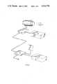
- FIG. 1 is a schematic illustration of the components of this invention.
- FIG. 2 illustrates a flow chart for the control of the detection circuitry.
- FIG. 3 is a schematic illustration of a micro processor used in controlling the detection circuit.
- FIGS. 4A-4C show the circuit diagram of the detection circuit which is connected to the micro processor of FIG. 3.
- FIG. 5 illustrates the ball identification capsule.
- FIG. 6 is a circuit diagram of a ball identification capsule.
- FIG. 7 shows the general arrangement of ball chutes and detector.
- a table ball game has a ball playing surface, and a plurality of pockets for the reception of balls, each pocket having ducting associated therewith leading to a Detector Assembly 10, and a ball holding area beyond the detector.
- the detector is controlled by Detector Electronics 11, which can be coupled to other table related functions 12 and a game scoring and display electronics module 13 which is in turn connected to a display 14 and other game related functions 15.
- the table related functions 12 could include a conventional coin mechanism and means for allowing access to balls to allow the game to be played.
- the other game related functions could include connection to a master score board controlling several tables, means for connection to additional similar systems for championship play-off at remote locations, means for storing the highest score played, and displaying this on the display, and means for providing audio or visual messages during the course of play.
- Each ball 16 has an identification capsule embedded within the ball at the time of manufacture.
- the capsule contains a code with more than one element so that error checking is possible.
- the capsule provides impact protection for the code element.
- the code elements consist of an inductance and capacitance connected together, with each code element tuned to a selected frequency. Multiple elements in each ball are each tuned to a different selected frequency and enough combinations of elements and frequencies are chosen to allow the required number of balls to be identified.
- Balls pocketed during a game are ducted to pass through the Detector Assembly 10 which preferably consists of multiple coils arranged with multiple magnetic axes so that the ball orientation is unimportant.
- the detector has multiple attempts to read each ball.
- the coils are tuned by a voltage controlled variable capacitance diode and the detector electronics control the voltage supplied to the diode in a manner that causes the detector coil to search for the frequency assigned to the code elements in the ball.
- the detector electronics also monitor the level of voltage in the detector coils, as the coil voltage will be at certain levels with no balls present and at different levels for selected frequencies when the code element of a selected frequency is inside the detector coil. Means are provided to sense the altered level to this to decide that a selected frequency is present.
- the detector electronics looks at the selected frequencies found and recognizes them as an identification number which is distinctive for a particular ball. This information is then transmitted to the display electronics for games scoring and display purposes. Invalid combinations of frequencies are ignored.
- the code elements have frequencies chosen from a series of n frequencies and where two or more code elements are provided in each ball, it is preferred that the frequencies assigned to each code element in the ball are different and are not adjacent to one another. For example, to be able to detect 21 different balls, 8 frequencies are selected and each ball is assigned two code elements of different frequencies. To improve frequency discrimination, adjacent selected frequencies are not used, yielding 21 possible code combinations. In the circuit illustrated in FIG. 4, the detector operates at 8 frequencies between 3.5 MHz and 6.5 MHz.
- the ball identification capsule is shown in FIG. 5 and its circuit is shown in FIG. 6.
- Each capsule preferably consists of a pair of resonant circuits having an inductance L1 or L2 and conveniently, each inductance is identical and wound on a ferrite drum core, connected to fixed capacities C1 and C4 and adjustable ceramic trimmer capacitor C2 and C3 enabling each circuit to be tuned for maximum effect at its selected frequency. Once tuned, the capsule can then be sealed and encapsulated within a ball.
- the detector assembly may consist of several coils, or may consist of a single coil with taps in a complex pattern to provide sensitivity at three orthogonal cartesian axes.
- the micro processor of FIG. 3 presents a parallel digital word to the Digital to Analog Convertor (DAC), (X6) and operates the Strobe line to input the digital word into the DAC.
- the analog output from the DAC is buffered by Amplifier X5a.
- Resistors R16,R30,R27 provide a minimum analog voltage to the DAC, while Amplifier X5b provides a maximum analog voltage to the DAC.
- the output from Amplifier X5a is defined within these voltages as a function of the digital word.
- the voltage difference between Amplifier X5a and Variable Resistance VR2 is fed to Amplifier X4a. Voltage and other values given in this circuit are given by way of example only to facilitate illustration of the operation of the circuit.
- a proportion of the output from Amplifier X4a is fed back to the DAC via resistors R33, R32, VR3 and the buffer amplifier X5b, to cause a multiplying action on the relationship of the output from the Amplifier X4a to the digital word.
- the output from Amplifier X4a also provides the tuning diode D12 with a bias voltage that controls the tuning diode capacitance.
- Detector Coil L1, and Tuning Diode D12 form a tuned resonant circuit with oscillation maintained by coupling capacitors C1, C3 and transistors X1c, X1d.
- DC bias conditions for the transistors X1c, X1d are controlled by resistors R2, R4, R5, R6, R10, VR1 and Voltage Divider Chain R7, R11, R12. Resistors R4, R5 cause current sharing at low current levels whilst Variable Resistors VR1 sets the oscillator activity level.
- Transistors X1a and X1b are connected in common base configuration to reduce transistor loading effects on the coil L1.
- Amplifier X2 monitors the oscillation level of the detector coil and provides amplification to drive Detector D1, TR1.
- the detector output is developed across Resistor R23 (at Test Point TP1) and is smoothed by Capacitor C21, and part of it is fed via Resistors R3, R2, VR1 to control the oscillator maximum level.
- the amplifier gain is controlled by the network R20, R39, L2, which also provides limited frequency emphasis, and via R3 provides a leveling effect at the detector as the frequency is varied.
- Resistors R8, R9 isolate amplifier input loading effects from the detector coil.
- Amplifier X2 has two complementary outputs, one being used to drive the detector while the other drives an output suitable for connecting to a counter (at TP2) to show the detector coil frequency during set up procedures.
- Amplifier X4b is used as a comparator, with its output going high when its inverting input, connected to the detector output (at TP1), goes lower than the voltage input at the junction of R15, R18.
- the comparator output is divided down by R19, R26 and fed to Darlington transistor TR2 which provides enough current to light LED D3 for visible indication of detection, and to provide the output signal to the microprocessor via R25.
- Resistor R38 is connected across the transistor output to insure a low level when TR2 is off.
- the microprocessor provides 15 volts DC to the detector and three other voltages can be generated in the power supply section of the electronics. 5 volts is generated by an integrated circuit linear regulator X7. 10 volts is generated by a Zener diode shunt regulator D2 and used to supply amplifier X2.
- the 34 volt bias voltage for the tuning diode is generated by a voltage multiplier connected to the output of a CMOS Schmitt trigger integrated circuit, with one section as an oscillator and three sections paralleled as a driver.
- the operation of the microprocessor is shown by the flow chart in FIG. 2 and shows how the digital words are generated and fed in series to the digital to analog converter which generates a voltage which is applied to the tuning diode which causes the oscillator frequency to move to the selected frequencies under control of the value of the digital word.
- This action tests for each of the selected eight frequencies in rapid and cyclic succession. While each frequency is being output, the detector is checked for response and if two valid frequencies are found, the ball is recognized and its identification is then passed to the game scoring electronics.
- FIG. 7 shows the general arrangement of chutes 21 from the pockets 22. These chutes lie beneath the playing surface 23 and are inclined so as to allow balls 16 to travel towards the detector 10 and then to a ball holding area 24 which may be coupled to a coin release mechanism enabling balls to be released at the commencement of a game.
- This game is the standard game, as played universally.
- Balls There are 16 balls associated with the game, including the cue ball. Balls fall into two groups, commonly unders and overs (under 8 or over 8) and are numbered, or otherwise identified to separate groups.
- the ball numbers will be displayed on the panel in two groups, unders and overs.
- Each team takes turns to selectively pocket balls, in such a way that they are assisted to gain a Poker hand, or their opponents are prevented from doing so.
- the Joker is a wild ball, and is the last ball to be pocketed.
- the cue ball is returned when pocketed, and does not have any effect on the score.
- a corresponding indicator panel on the wall display unit is lit, in the group of indicators associated with each player or team.
- Each group of indicators is laid out in suits, with graphical display of the corresponding card in front.
- a preferred indicator panel involves the use of electronically controlled flip cards, each card being provided with the appropriate graphics to represent a designated card corresponding to the balls, so that when that particular ball is pocketed, the ball will be recognized by the detector electronics which will then cause the appropriate flip card to flip over presenting the appropriate graphics indicating that that ball has been scored.
- circuit of this invention has been described with particular reference to the scoring of balls in different types of pool games, it will be appreciated that the invention can be used in any table ball game in which the passage of balls into ball traps is to be scored.
- the preferred arrangement utilizes passive resonant circuits embedded within the ball, other identification means could be used including active circuits, optical characteristics, magnetic identify capsules, or any other identification means which could be read by detection means and provide an output to scoring means.
Abstract
Description
______________________________________
            Identification
______________________________________
Hearts
10            1
J             2
Q             3
K             4
A             5
Diamonds
10            6
J             7
Q             8
K             9
A             10
Clubs
10            11
J             12
Q             13
K             14
A             15
Spades
10            16
J             17
Q             18
K             19
A             20
Joker         21
Cue Ball      None
______________________________________
______________________________________ e.g.:SPADE 10J Q K A CLUB 10J Q K A DIAMOND 10J Q K A HEART 10 J Q K A J ______________________________________
Claims (7)
Priority Applications (16)
| Application Number | Priority Date | Filing Date | Title |
|---|---|---|---|
| US06/452,729 US4516770A (en) | 1982-12-23 | 1982-12-23 | Ball identification for a table ball game |
| NZ203945A NZ203945A (en) | 1982-12-23 | 1983-04-20 | Table ball game:resonant circuits embedded within balls |
| NZ21118083A NZ211180A (en) | 1982-12-23 | 1983-04-20 | Poker pool:electronic identification and detection of balls |
| AU14135/83A AU558438B2 (en) | 1982-12-23 | 1983-05-02 | Table ball game |
| DE8383307602T DE3381398D1 (en) | 1982-12-23 | 1983-12-14 | TABLE GAME WITH BALLS. |
| AT83307602T ATE51534T1 (en) | 1982-12-23 | 1983-12-14 | TABLE GAME WITH BALLS. |
| EP83307602A EP0112686B1 (en) | 1982-12-23 | 1983-12-14 | Table ball games |
| DE8585200775T DE3381490D1 (en) | 1982-12-23 | 1983-12-14 | GAME AND PLAYING DEVICE. |
| AT85200775T ATE52194T1 (en) | 1982-12-23 | 1983-12-14 | GAME AND GAMES. |
| EP85200775A EP0159763B1 (en) | 1982-12-23 | 1983-12-14 | Game and apparatus |
| CA000443554A CA1206174A (en) | 1982-12-23 | 1983-12-16 | Table ball games |
| JP58243620A JPS59151975A (en) | 1982-12-23 | 1983-12-23 | Table ball game machine |
| US06/664,365 US4878664A (en) | 1982-12-23 | 1984-10-24 | Poker pool game |
| AU38459/85A AU557998B2 (en) | 1982-12-23 | 1985-02-05 | Table ball game |
| JP60074168A JPS60253470A (en) | 1982-12-23 | 1985-04-08 | Table ball game machine |
| CA000487181A CA1256134A (en) | 1981-12-23 | 1985-07-19 | Table ball game |
Applications Claiming Priority (1)
| Application Number | Priority Date | Filing Date | Title |
|---|---|---|---|
| US06/452,729 US4516770A (en) | 1982-12-23 | 1982-12-23 | Ball identification for a table ball game |
Related Child Applications (1)
| Application Number | Title | Priority Date | Filing Date |
|---|---|---|---|
| US06/664,365 Continuation-In-Part US4878664A (en) | 1982-12-23 | 1984-10-24 | Poker pool game |
Publications (1)
| Publication Number | Publication Date |
|---|---|
| US4516770A true US4516770A (en) | 1985-05-14 |
Family
ID=23797682
Family Applications (1)
| Application Number | Title | Priority Date | Filing Date |
|---|---|---|---|
| US06/452,729 Expired - Fee Related US4516770A (en) | 1981-12-23 | 1982-12-23 | Ball identification for a table ball game |
Country Status (8)
| Country | Link |
|---|---|
| US (1) | US4516770A (en) |
| EP (2) | EP0159763B1 (en) |
| JP (2) | JPS59151975A (en) |
| AT (2) | ATE52194T1 (en) |
| AU (2) | AU558438B2 (en) |
| CA (1) | CA1206174A (en) |
| DE (2) | DE3381490D1 (en) |
| NZ (1) | NZ203945A (en) |
Cited By (25)
| Publication number | Priority date | Publication date | Assignee | Title |
|---|---|---|---|---|
| US4840376A (en) * | 1986-11-21 | 1989-06-20 | Cardball International Limited | Poker and pool apparatus |
| US4878664A (en) * | 1982-12-23 | 1989-11-07 | Development Finance Corporation | Poker pool game |
| US4948128A (en) * | 1989-01-13 | 1990-08-14 | Emery Ii George B | Poker pool table |
| US5026053A (en) * | 1989-12-28 | 1991-06-25 | Entertainment International, Inc. 1987 | Billiard table multiple electronics game device and method |
| US5066008A (en) * | 1990-04-05 | 1991-11-19 | Rivera Roberto S | Electronic voice and control system for billiards |
| US5083113A (en) * | 1990-01-31 | 1992-01-21 | Texas Instruments Incorporated | Inductive coupled object identification system and method |
| US5738591A (en) * | 1993-05-04 | 1998-04-14 | Opsal; David R. | Queuing system |
| US5743815A (en) * | 1996-07-18 | 1998-04-28 | Helderman; Michael D. | Golf ball and indentification system |
| US6607123B1 (en) | 1998-03-19 | 2003-08-19 | S World Golf Systems Ltd. | Identifying golf balls |
| US20040127283A1 (en) * | 2002-12-17 | 2004-07-01 | Martin John R. | Parlor game |
| US7307411B1 (en) * | 2005-06-03 | 2007-12-11 | Sensor Platforms, Inc. | Method for signal extraction in a universal sensor IC |
| US20080182675A1 (en) * | 2007-01-25 | 2008-07-31 | Amal Flores | Methods and apparatuses for time-constrained games of billiards, pool and the like |
| US20090131186A1 (en) * | 2007-11-15 | 2009-05-21 | Arachnid Inc. | Parlor game |
| US20090170602A1 (en) * | 2007-12-27 | 2009-07-02 | Arachnid Inc. | System and method for controlling the operation of an entertainment unit |
| US20090233697A1 (en) * | 2008-02-04 | 2009-09-17 | Aristocrat Technologies Australia Pty Limited | Method of gaming, a gaming system, and a gaming apparatus |
| US8052538B1 (en) * | 2006-09-15 | 2011-11-08 | Emery Iii George B | Poker billiard table and game |
| US9152249B2 (en) | 2008-10-20 | 2015-10-06 | Sensor Platforms, Inc. | System and method for determining an attitude of a device undergoing dynamic acceleration |
| US9228842B2 (en) | 2012-03-25 | 2016-01-05 | Sensor Platforms, Inc. | System and method for determining a uniform external magnetic field |
| US9248368B2 (en) | 2012-09-04 | 2016-02-02 | Toccata Gaming International, Llc | Automated remote play cue sport system |
| US9316513B2 (en) | 2012-01-08 | 2016-04-19 | Sensor Platforms, Inc. | System and method for calibrating sensors for different operating environments |
| US9459276B2 (en) | 2012-01-06 | 2016-10-04 | Sensor Platforms, Inc. | System and method for device self-calibration |
| US9795865B2 (en) | 2012-09-04 | 2017-10-24 | Toccata Gaming International, Llc | Automated remote play cue sport system |
| US10055941B2 (en) | 2010-08-18 | 2018-08-21 | Edge Technology, Llc. | High integrity golf wagering system |
| US10300339B2 (en) | 2010-08-18 | 2019-05-28 | Edge Technology | Golf ball with RFID inlay between a split core |
| US11724172B2 (en) | 2015-07-09 | 2023-08-15 | World Golf Systems Limited | Ball game apparatus |
Families Citing this family (12)
| Publication number | Priority date | Publication date | Assignee | Title |
|---|---|---|---|---|
| GB2207359B (en) * | 1987-06-11 | 1991-05-01 | William Joseph Duggan | Improvements in relating to a game |
| US5062635A (en) * | 1989-07-25 | 1991-11-05 | Tse Kam Y | Number generating device with magnetic biasing means |
| JPH069656U (en) * | 1991-11-26 | 1994-02-08 | 株式会社ダイケン | Fire extinguisher pole |
| JPH069655U (en) * | 1991-11-26 | 1994-02-08 | 株式会社ダイケン | Fire extinguisher pole |
| JPH069657U (en) * | 1991-12-13 | 1994-02-08 | 株式会社ダイケン | Fire extinguisher pole |
| JPH0619752U (en) * | 1992-01-29 | 1994-03-15 | 株式会社ダイケン | Fire extinguisher pole |
| BE1005848A3 (en) * | 1992-06-05 | 1994-02-15 | Wielemans Eric | Installation for a ball game, in particular using golf clubs and balls |
| DE4418761A1 (en) * | 1994-05-28 | 1996-03-21 | Nsm Ag | Device for recording goal hits in ball games |
| GB2313556B (en) * | 1996-05-27 | 1999-06-23 | Thomas Clinton Kilpatrick | A board game of skill |
| JP3035174U (en) * | 1996-08-28 | 1997-03-11 | モリタ工業株式会社 | Fire extinguisher prank prevention device |
| DE10114235A1 (en) * | 2001-03-22 | 2002-09-26 | Form Orange Produktentwicklung | Spherical object identification method e.g. for pool balls, uses electronic identification chip and cooperating sensors |
| JP4747479B2 (en) * | 2001-09-27 | 2011-08-17 | 株式会社カクダイ | Water faucet with article mounting base plate, water faucet with article hanging hook, article mounting base plate and water faucet with article hanging hook |
Citations (12)
| Publication number | Priority date | Publication date | Assignee | Title |
|---|---|---|---|---|
| US2825565A (en) * | 1956-09-17 | 1958-03-04 | Raymond T Moloney | Color-selective ball game register |
| US3760404A (en) * | 1972-07-07 | 1973-09-18 | G Sergeevich | Chess game progress demonstration device |
| US3843132A (en) * | 1973-04-19 | 1974-10-22 | D Ferguson | Board game move recording system |
| US4015845A (en) * | 1976-02-17 | 1977-04-05 | Sines Randy D | Automatic cue ball separating and return assembly for billiard tables |
| SU566594A1 (en) * | 1973-12-18 | 1977-07-30 | Пермский ордена Трудового Красного Знамени государственный университет им. А.М.Горького | Chess play demonstrating apparatus |
| US4116435A (en) * | 1977-03-18 | 1978-09-26 | Randy D. Sines | Automatic cue ball separating device for billiard tables |
| DE3001924A1 (en) * | 1980-01-19 | 1981-07-30 | Nsm-Apparatebau Gmbh & Co Kg, 6530 Bingen | ENTERTAINMENT PLAYER |
| SU878324A1 (en) * | 1980-02-19 | 1981-11-07 | Artsybashev Viktor K | Device for demonstration of chess play |
| US4327920A (en) * | 1980-03-17 | 1982-05-04 | Ideal Toy Corporation | Electromechanical decision making board game |
| US4355802A (en) * | 1979-05-14 | 1982-10-26 | Montana Billiard Supply | Billiard table |
| US4375289A (en) * | 1977-07-19 | 1983-03-01 | PRECITEC Gesellschaft fur Prazisionstechnik und Elektronik mbH & Co. Entwicklungs und Vertriebs-KG | Apparatus for monitoring a boundary line |
| US4391447A (en) * | 1980-11-20 | 1983-07-05 | Raymond Dudley | Electronic chess game |
Family Cites Families (11)
| Publication number | Priority date | Publication date | Assignee | Title |
|---|---|---|---|---|
| US580253A (en) * | 1897-04-06 | Richard g | ||
| US666333A (en) * | 1894-04-12 | 1901-01-22 | George H Stevens | Pool or billiard ball. |
| US1578005A (en) * | 1923-01-25 | 1926-03-23 | Max L Brooks | Game apparatus |
| US2237746A (en) * | 1939-03-16 | 1941-04-08 | Perks Gertrude Elsie Ruby | Automatic game device |
| US3680859A (en) * | 1970-06-29 | 1972-08-01 | John R English | Combined billiard balls rack and indicator for placing the balls |
| JPS4988866U (en) * | 1972-11-06 | 1974-08-01 | ||
| JPS5020781U (en) * | 1973-06-21 | 1975-03-08 | ||
| US4002339A (en) * | 1974-11-20 | 1977-01-11 | Reiner Lawrence L | Poker pool game |
| JPS5629509Y2 (en) * | 1976-09-24 | 1981-07-14 | ||
| GB2005552A (en) * | 1977-06-30 | 1979-04-25 | Burton G | Automatically scoring billiards-type games |
| DE3135846A1 (en) * | 1981-09-10 | 1983-04-28 | Horst 2741 Kutenholz Erzmoneit | BILLIARDS |
-
1982
- 1982-12-23 US US06/452,729 patent/US4516770A/en not_active Expired - Fee Related
-
1983
- 1983-04-20 NZ NZ203945A patent/NZ203945A/en unknown
- 1983-05-02 AU AU14135/83A patent/AU558438B2/en not_active Ceased
- 1983-12-14 EP EP85200775A patent/EP0159763B1/en not_active Expired - Lifetime
- 1983-12-14 EP EP83307602A patent/EP0112686B1/en not_active Expired - Lifetime
- 1983-12-14 DE DE8585200775T patent/DE3381490D1/en not_active Expired - Lifetime
- 1983-12-14 DE DE8383307602T patent/DE3381398D1/en not_active Expired - Lifetime
- 1983-12-14 AT AT85200775T patent/ATE52194T1/en active
- 1983-12-14 AT AT83307602T patent/ATE51534T1/en not_active IP Right Cessation
- 1983-12-16 CA CA000443554A patent/CA1206174A/en not_active Expired
- 1983-12-23 JP JP58243620A patent/JPS59151975A/en active Granted
-
1985
- 1985-02-05 AU AU38459/85A patent/AU557998B2/en not_active Ceased
- 1985-04-08 JP JP60074168A patent/JPS60253470A/en active Pending
Patent Citations (12)
| Publication number | Priority date | Publication date | Assignee | Title |
|---|---|---|---|---|
| US2825565A (en) * | 1956-09-17 | 1958-03-04 | Raymond T Moloney | Color-selective ball game register |
| US3760404A (en) * | 1972-07-07 | 1973-09-18 | G Sergeevich | Chess game progress demonstration device |
| US3843132A (en) * | 1973-04-19 | 1974-10-22 | D Ferguson | Board game move recording system |
| SU566594A1 (en) * | 1973-12-18 | 1977-07-30 | Пермский ордена Трудового Красного Знамени государственный университет им. А.М.Горького | Chess play demonstrating apparatus |
| US4015845A (en) * | 1976-02-17 | 1977-04-05 | Sines Randy D | Automatic cue ball separating and return assembly for billiard tables |
| US4116435A (en) * | 1977-03-18 | 1978-09-26 | Randy D. Sines | Automatic cue ball separating device for billiard tables |
| US4375289A (en) * | 1977-07-19 | 1983-03-01 | PRECITEC Gesellschaft fur Prazisionstechnik und Elektronik mbH & Co. Entwicklungs und Vertriebs-KG | Apparatus for monitoring a boundary line |
| US4355802A (en) * | 1979-05-14 | 1982-10-26 | Montana Billiard Supply | Billiard table |
| DE3001924A1 (en) * | 1980-01-19 | 1981-07-30 | Nsm-Apparatebau Gmbh & Co Kg, 6530 Bingen | ENTERTAINMENT PLAYER |
| SU878324A1 (en) * | 1980-02-19 | 1981-11-07 | Artsybashev Viktor K | Device for demonstration of chess play |
| US4327920A (en) * | 1980-03-17 | 1982-05-04 | Ideal Toy Corporation | Electromechanical decision making board game |
| US4391447A (en) * | 1980-11-20 | 1983-07-05 | Raymond Dudley | Electronic chess game |
Cited By (29)
| Publication number | Priority date | Publication date | Assignee | Title |
|---|---|---|---|---|
| US4878664A (en) * | 1982-12-23 | 1989-11-07 | Development Finance Corporation | Poker pool game |
| US4840376A (en) * | 1986-11-21 | 1989-06-20 | Cardball International Limited | Poker and pool apparatus |
| US4948128A (en) * | 1989-01-13 | 1990-08-14 | Emery Ii George B | Poker pool table |
| US5026053A (en) * | 1989-12-28 | 1991-06-25 | Entertainment International, Inc. 1987 | Billiard table multiple electronics game device and method |
| US5083113A (en) * | 1990-01-31 | 1992-01-21 | Texas Instruments Incorporated | Inductive coupled object identification system and method |
| US5066008A (en) * | 1990-04-05 | 1991-11-19 | Rivera Roberto S | Electronic voice and control system for billiards |
| US5738591A (en) * | 1993-05-04 | 1998-04-14 | Opsal; David R. | Queuing system |
| US5743815A (en) * | 1996-07-18 | 1998-04-28 | Helderman; Michael D. | Golf ball and indentification system |
| US6607123B1 (en) | 1998-03-19 | 2003-08-19 | S World Golf Systems Ltd. | Identifying golf balls |
| US20040127283A1 (en) * | 2002-12-17 | 2004-07-01 | Martin John R. | Parlor game |
| US7384341B2 (en) * | 2002-12-17 | 2008-06-10 | Arachnid Inc. | Parlor game |
| US7307411B1 (en) * | 2005-06-03 | 2007-12-11 | Sensor Platforms, Inc. | Method for signal extraction in a universal sensor IC |
| US8052538B1 (en) * | 2006-09-15 | 2011-11-08 | Emery Iii George B | Poker billiard table and game |
| US20080182675A1 (en) * | 2007-01-25 | 2008-07-31 | Amal Flores | Methods and apparatuses for time-constrained games of billiards, pool and the like |
| US20090131186A1 (en) * | 2007-11-15 | 2009-05-21 | Arachnid Inc. | Parlor game |
| US8016687B2 (en) | 2007-11-15 | 2011-09-13 | Arachnid Inc. | Parlor game |
| US20090170602A1 (en) * | 2007-12-27 | 2009-07-02 | Arachnid Inc. | System and method for controlling the operation of an entertainment unit |
| US20090233697A1 (en) * | 2008-02-04 | 2009-09-17 | Aristocrat Technologies Australia Pty Limited | Method of gaming, a gaming system, and a gaming apparatus |
| US8241136B2 (en) | 2008-02-04 | 2012-08-14 | Aristocrat Technologies Australia Pty Limited | Method of gaming, a gaming system, and a gaming apparatus |
| US9089764B2 (en) | 2008-02-04 | 2015-07-28 | Aristocrat Technologies Australia Pty Limited | Method of gaming, a gaming system and a gaming apparatus |
| US9152249B2 (en) | 2008-10-20 | 2015-10-06 | Sensor Platforms, Inc. | System and method for determining an attitude of a device undergoing dynamic acceleration |
| US10055941B2 (en) | 2010-08-18 | 2018-08-21 | Edge Technology, Llc. | High integrity golf wagering system |
| US10300339B2 (en) | 2010-08-18 | 2019-05-28 | Edge Technology | Golf ball with RFID inlay between a split core |
| US9459276B2 (en) | 2012-01-06 | 2016-10-04 | Sensor Platforms, Inc. | System and method for device self-calibration |
| US9316513B2 (en) | 2012-01-08 | 2016-04-19 | Sensor Platforms, Inc. | System and method for calibrating sensors for different operating environments |
| US9228842B2 (en) | 2012-03-25 | 2016-01-05 | Sensor Platforms, Inc. | System and method for determining a uniform external magnetic field |
| US9248368B2 (en) | 2012-09-04 | 2016-02-02 | Toccata Gaming International, Llc | Automated remote play cue sport system |
| US9795865B2 (en) | 2012-09-04 | 2017-10-24 | Toccata Gaming International, Llc | Automated remote play cue sport system |
| US11724172B2 (en) | 2015-07-09 | 2023-08-15 | World Golf Systems Limited | Ball game apparatus |
Also Published As
| Publication number | Publication date |
|---|---|
| EP0159763B1 (en) | 1990-04-25 |
| JPS6329552B2 (en) | 1988-06-14 |
| NZ203945A (en) | 1987-01-23 |
| DE3381398D1 (en) | 1990-05-10 |
| EP0112686B1 (en) | 1990-04-04 |
| AU557998B2 (en) | 1987-01-15 |
| ATE51534T1 (en) | 1990-04-15 |
| AU3845985A (en) | 1985-06-06 |
| EP0112686A3 (en) | 1986-02-19 |
| CA1206174A (en) | 1986-06-17 |
| JPS59151975A (en) | 1984-08-30 |
| EP0159763A2 (en) | 1985-10-30 |
| AU1413583A (en) | 1984-06-28 |
| DE3381490D1 (en) | 1990-05-31 |
| JPS60253470A (en) | 1985-12-14 |
| EP0159763A3 (en) | 1986-02-12 |
| ATE52194T1 (en) | 1990-05-15 |
| EP0112686A2 (en) | 1984-07-04 |
| AU558438B2 (en) | 1987-01-29 |
Similar Documents
| Publication | Publication Date | Title |
|---|---|---|
| US4516770A (en) | Ball identification for a table ball game | |
| US4380334A (en) | Electronic card game simulator | |
| US6645072B1 (en) | Portable electronic bingo device | |
| US3796433A (en) | Electronic gaming device simulating the game of blackjack | |
| US6869074B2 (en) | Gaming devices and methods of playing card games with indicator of cards played from previous hands | |
| US6299534B1 (en) | Gaming apparatus with proximity switch | |
| US6176781B1 (en) | Electronic amusement device and method for operating same | |
| US5031914A (en) | Electronic dice game | |
| US7520510B2 (en) | Playing cards | |
| US5669817A (en) | Casino card table with video display | |
| US5019973A (en) | Poker game method | |
| US20020103017A1 (en) | Electronic card game and method | |
| US5637844A (en) | Process and system for automated running of sports contests | |
| RU2004106786A (en) | MONITORING / TRACKING SYSTEM CASINO SCOREBOARD | |
| CA2195329A1 (en) | Gaming Equipment for Professional Use of Table Games with Playing Cards and Gaming Chips, in Particular for the Game of "Black Jack" | |
| US4878664A (en) | Poker pool game | |
| GB2382034A (en) | Betting game scoring and monitoring | |
| GB2369303A (en) | A golf driving range games system and method | |
| US4314336A (en) | Electronic card game simulator | |
| US7118477B1 (en) | Portable electronic bingo device | |
| US4017085A (en) | Golf game | |
| US4569529A (en) | Game board with slides and cards | |
| CA1256134A (en) | Table ball game | |
| US4968030A (en) | Electronic cribbage board and game scoring device | |
| US2355927A (en) | Game |
Legal Events
| Date | Code | Title | Description |
|---|---|---|---|
| AS | Assignment |
Owner name: BROOKES,DAVID LESLIE Free format text: ASSIGNMENT OF ASSIGNORS INTEREST.;ASSIGNORS:BROOKES, DAVID L.;WEATHERLY, JOHN D.;DILLICAR, COLIN R.;REEL/FRAME:004081/0805 Effective date: 19821123 Owner name: SEDON,HERBERT BRUCE Free format text: ASSIGNMENT OF ASSIGNORS INTEREST.;ASSIGNORS:BROOKES, DAVID L.;WEATHERLY, JOHN D.;DILLICAR, COLIN R.;REEL/FRAME:004081/0805 Effective date: 19821123 Owner name: BROOKES,DAVID LESLIE, VIRGINIA Free format text: ASSIGNMENT OF ASSIGNORS INTEREST;ASSIGNORS:BROOKES, DAVID L.;WEATHERLY, JOHN D.;DILLICAR, COLIN R.;REEL/FRAME:004081/0805 Effective date: 19821123 Owner name: SEDON,HERBERT BRUCE, VIRGINIA Free format text: ASSIGNMENT OF ASSIGNORS INTEREST;ASSIGNORS:BROOKES, DAVID L.;WEATHERLY, JOHN D.;DILLICAR, COLIN R.;REEL/FRAME:004081/0805 Effective date: 19821123 |
|
| AS | Assignment |
Owner name: RON PARKER LIMITED 1978 GREAT NORTH RD AVONDALE AU Free format text: ASSIGNMENT OF ASSIGNORS INTEREST.;ASSIGNORS:SEDON HERBERT B.;BROOKES, DAVID L.;REEL/FRAME:004154/0541 Effective date: 19830712 |
|
| AS | Assignment |
Owner name: DELELOPMENT FINANCE CORPORATION OF NEW ZEALAND 350 Free format text: ASSIGNMENT OF ASSIGNORS INTEREST.;ASSIGNOR:RON PARKER LTD LIMITED;REEL/FRAME:004217/0929 Effective date: 19831201 |
|
| FEPP | Fee payment procedure |
Free format text: PAYOR NUMBER ASSIGNED (ORIGINAL EVENT CODE: ASPN); ENTITY STATUS OF PATENT OWNER: SMALL ENTITY |
|
| FPAY | Fee payment |
Year of fee payment: 4 |
|
| LAPS | Lapse for failure to pay maintenance fees | ||
| FP | Lapsed due to failure to pay maintenance fee |
Effective date: 19930516 |
|
| STCH | Information on status: patent discontinuation |
Free format text: PATENT EXPIRED DUE TO NONPAYMENT OF MAINTENANCE FEES UNDER 37 CFR 1.362 |