US4510559A - Lamp and filter mounting assembly - Google Patents
Lamp and filter mounting assembly Download PDFInfo
- Publication number
- US4510559A US4510559A US06/521,037 US52103783A US4510559A US 4510559 A US4510559 A US 4510559A US 52103783 A US52103783 A US 52103783A US 4510559 A US4510559 A US 4510559A
- Authority
- US
- United States
- Prior art keywords
- lamp
- mounting
- assembly
- aperture
- filter
- Prior art date
- Legal status (The legal status is an assumption and is not a legal conclusion. Google has not performed a legal analysis and makes no representation as to the accuracy of the status listed.)
- Expired - Fee Related
Links
Images

Classifications
-
- F—MECHANICAL ENGINEERING; LIGHTING; HEATING; WEAPONS; BLASTING
- F21—LIGHTING
- F21V—FUNCTIONAL FEATURES OR DETAILS OF LIGHTING DEVICES OR SYSTEMS THEREOF; STRUCTURAL COMBINATIONS OF LIGHTING DEVICES WITH OTHER ARTICLES, NOT OTHERWISE PROVIDED FOR
- F21V21/00—Supporting, suspending, or attaching arrangements for lighting devices; Hand grips
- F21V21/14—Adjustable mountings
- F21V21/30—Pivoted housings or frames
-
- F—MECHANICAL ENGINEERING; LIGHTING; HEATING; WEAPONS; BLASTING
- F21—LIGHTING
- F21V—FUNCTIONAL FEATURES OR DETAILS OF LIGHTING DEVICES OR SYSTEMS THEREOF; STRUCTURAL COMBINATIONS OF LIGHTING DEVICES WITH OTHER ARTICLES, NOT OTHERWISE PROVIDED FOR
- F21V17/00—Fastening of component parts of lighting devices, e.g. shades, globes, refractors, reflectors, filters, screens, grids or protective cages
- F21V17/10—Fastening of component parts of lighting devices, e.g. shades, globes, refractors, reflectors, filters, screens, grids or protective cages characterised by specific fastening means or way of fastening
- F21V17/104—Fastening of component parts of lighting devices, e.g. shades, globes, refractors, reflectors, filters, screens, grids or protective cages characterised by specific fastening means or way of fastening using feather joints, e.g. tongues and grooves, with or without friction
-
- F—MECHANICAL ENGINEERING; LIGHTING; HEATING; WEAPONS; BLASTING
- F21—LIGHTING
- F21V—FUNCTIONAL FEATURES OR DETAILS OF LIGHTING DEVICES OR SYSTEMS THEREOF; STRUCTURAL COMBINATIONS OF LIGHTING DEVICES WITH OTHER ARTICLES, NOT OTHERWISE PROVIDED FOR
- F21V17/00—Fastening of component parts of lighting devices, e.g. shades, globes, refractors, reflectors, filters, screens, grids or protective cages
- F21V17/10—Fastening of component parts of lighting devices, e.g. shades, globes, refractors, reflectors, filters, screens, grids or protective cages characterised by specific fastening means or way of fastening
- F21V17/16—Fastening of component parts of lighting devices, e.g. shades, globes, refractors, reflectors, filters, screens, grids or protective cages characterised by specific fastening means or way of fastening by deformation of parts; Snap action mounting
- F21V17/164—Fastening of component parts of lighting devices, e.g. shades, globes, refractors, reflectors, filters, screens, grids or protective cages characterised by specific fastening means or way of fastening by deformation of parts; Snap action mounting the parts being subjected to bending, e.g. snap joints
-
- F—MECHANICAL ENGINEERING; LIGHTING; HEATING; WEAPONS; BLASTING
- F21—LIGHTING
- F21V—FUNCTIONAL FEATURES OR DETAILS OF LIGHTING DEVICES OR SYSTEMS THEREOF; STRUCTURAL COMBINATIONS OF LIGHTING DEVICES WITH OTHER ARTICLES, NOT OTHERWISE PROVIDED FOR
- F21V19/00—Fastening of light sources or lamp holders
- F21V19/04—Fastening of light sources or lamp holders with provision for changing light source, e.g. turret
-
- F—MECHANICAL ENGINEERING; LIGHTING; HEATING; WEAPONS; BLASTING
- F21—LIGHTING
- F21W—INDEXING SCHEME ASSOCIATED WITH SUBCLASSES F21K, F21L, F21S and F21V, RELATING TO USES OR APPLICATIONS OF LIGHTING DEVICES OR SYSTEMS
- F21W2131/00—Use or application of lighting devices or systems not provided for in codes F21W2102/00-F21W2121/00
- F21W2131/40—Lighting for industrial, commercial, recreational or military use
Definitions
- the present invention relates to a new and improved lamp and filter mounting assembly and more particularly, to a lamp and filter mounting assembly that can be easily rotated to position a lamp in a selected angular position.
- a spot light or flood beam to illuminate objects or areas.
- One example of such lighting is a ceiling recess mounted spot light that is used to wash a wall with light or to highlight a painting hung on a wall.
- the utility of these lights is substantially enhanced if the angular position of the lamp may be varied allowing it to be adaptable to direct light on a wall, a floor or other location without the necessity of moving the light fixture. Since these lights are positioned within a recess in a ceiling or wall, it is also desirable that the lamp can be changed without the necessity of complete disassembly.
- One solution to these requirements is to provide a light that is not recessed in the ceiling. Such a light is disclosed in U.S. Pat. No. 4,310,870.
- the light disclosed in this patent takes up room space and may be subjected to damage due to exposure outside the ceiling or wall.
- Partially recessed lights have also been proposed as illustrated, for example, in U.S. Pat. Nos. 2,554,258; 2,922,030 and 3,300,634. These partially recessed lights also suffer from the disadvantage of being exposed and in some circumstances, from being unsightly and subject to damage.
- Another alternative has been to position the light within a recess and angularly position a reflecting shade to direct light as desired.
- Such a light is illustrated in U.S. Pat. No. 2,434,108.
- This lighting unit although recessed, includes a shade or reflector that must be pulled downwardly out of the recess resulting in the same disadvantages suffered by the lights disclosed in the other patents.
- a totally recessed light is illustrated in U.S. Pat. No. 2,465,248, but this light cannot be directed to light particular areas.
- An object of the present invention is to provide a new and improved lamp and filter mounting assembly.
- Another object of the present invention is to provide a new and improved lamp and filter mounting assembly that includes a self-contained filter.
- a further object of the present invention is to provide a new and improved lamp and filter mounting assembly that is easily adjustable.
- a still further object of the present invention is to provide a new and improved lamp and filter mounting assembly in which the lamp mounted in the assembly is easily replaced.
- Another object of the present invention is to provide a new and improved lamp and filter mounting assembly that can be used in a variety of applications.
- the present invention is directed to a new and improved lamp and filter mounting assembly for small, reflector type projector lamps.
- the assembly includes a bracket to which a lamp holder is pivotally secured.
- the lamp holder includes a lamp mounting plate on which the lamp is positioned.
- a back wall is secured to the lamp mounting plate and is pivotally mounted onto the bracket.
- An inclined adjustment stop is defined on the back wall and engages the mounting bracket upon rotation of the lamp holder through a predetermined angle.
- a filter holder which defines a planar surface on which a filter is mounted may also be included on the assembly.
- Side rails and a backstop on the holder hold the filter in position.
- the side rails include inwardly turned extensions allowing sliding attachment of the filter holder to the lamp holder.
- a latch mechanism is provided to latch the filter holder to the lamp holder.
- the bracket is secured to an aperture pan that is rotatably mounted on a trim assembly.
- a light shield surrounds the aperture panel and the entire assembly may be removably positioned within a recessed can in a ceiling or similar structure.
- FIG. 1 is a perspective view of a light assembly including a lamp and filter mounting assembly constructed in accordance with the principles of the present invention
- FIG. 2 is an enlarged view taken along line 2--2 of FIG. 1;
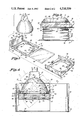
- FIG. 3 is a partial, exploded view of the lamp and filter mounting assembly
- FIG. 4 is a view taken along line 4--4 of FIG. 2 illustrating two angular positions of the lamp and filter mounting assembly
- FIG. 5 is a view similar to FIG. 2 illustrating an alternative embodiment.
- Light assembly 10 may be mounted in a can positioned within a recess in a ceiling, wall or similar structure (not shown).
- the light assembly 10 includes a lamp 12 which may be a flood light or a spot light.
- Lamp 12 includes terminals 14 which are to be connected to an electrical plug.
- Assembly 10 is intended to allow directional focusing of lamp 12 in different locations such as a portion of wall adjacent the assembly or a plant or table located beneath the light assembly.
- Lamp holder 16 As best seen in FIG. 3 includes a bottom wall 18 with parallel side walls 20 and 22. Bottom wall 18 defines a lamp mounting plate 24 on which lamp 12 rests. A central aperture 26 is defined in lamp mounting plate 24 beneath lamp 12. Spacer tabs 28 are fabricated in the rim of aperture 26 and are bent downwardly from lamp mounting plate 24.
- Lamp holder 16 includes a rear or back wall 30 with an aperture 32 and rivet holes 34.
- Back wall 30 may be rigidly secured to a bracket 36 by rivets in rivet holes 34 and through bracket 36. In this fixed position, the lamp 12 and lamp holder 16 may be used as a spot light as in a projector.
- a preferred procedure is to mount back wall 30 to bracket 36 in such a way as to allow angular rotation or movement of lamp holder 16. This is accomplished with an eyelet 38 secured within aperture 32 and a concentric aperture 39 formed in bracket 36 as best seen in FIG. 2.
- a spring washer 37 is positioned between the backwall 30 and bracket 36 to provide a tight yet rotatable connection.
- Stop 40 includes a first edge 42 and a second edge 44. In the substantially horizontal position of lamp mounting plate 24, the first edge 42 abuts the top end of bracket 36. From this position lamp holder 16 may be rotated counter-clockwise, as viewed from the lamp side (see FIG. 4), substantially through a 45° arc until the second edge 44 and the underside of adjustment stop 40 engages the top end of bracket 36. This rotation about the axis extending through the centers of apertures 32 and 39 allows directional focusing of light emanating from lamp 12.
- filter or lens 46 which may have transparent, translucent or colored, heat resistant glass.
- Filter 46 as illustrated in the preferred embodiment is square or rectangular, but it is to be understood that filter 46 may be of any desired shape.
- Filter 46 is held by a filter holder generally designated by the reference numeral 48 that includes a bottom wall 50 defining a filter mounting plate 52.
- the filter 46 is positioned slightly above the filter mounting plane 52 and held in part by a filter stop 54.
- a central recess 56 is defined in filter mounting plane 52 and is intended to be aligned with the aperture 26.
- a plurality of filter tensioning tabs 58 are fabricated in the rim of the aperture 56 and are bent upwardly from plane 52. Additional holding support of filter 46 is provided by side rails 60 which include inwardly and downwardly turned ends 62. Side rails 60 and downwardly turned ends 62 also function to provide sliding attachment of filger holder 48 to lamp holder 16. To join lamp holder 16 and filter holder 48, the inwardly turned ends 62 slide over sidewalls 20 and 22 of lamp holder 16.
- spacer tabs 28 engage the upper surface of filter 46 providing a space between the bottom wall 18 of lamp mounting plate 24 and filter 46.
- Filter 46 is biased upwardly against spacer tabs 28 by the tension tabs 58 to thereby provide a space between filter 46 and bottom wall 52.
- the spaces above and below filter 46 allow air circulation to disipate heat and also provide compensation for variances in the thickness of the glass of filter 46 and for heat expansion of filter 46.
- filter holder 48 is locked to the lamp holder 16 by a latch 64 and a latch tab 66.
- latch 64 extends over and locks onto tab 66.
- Rim 70 is engaged by the downward extending ends 62 of side rails 60 which also serve to captivate lamp 12, thereby holding it onto the lamp mounting plate 24.
- Lamp holder 16, filter holder 48 and bracket 36 are secured to an aperture pan 72 by spot welding or attaching by other means a leg 74 of bracket 36 to pan 72.
- Aperture pan 72 includes an elongated elliptical aperture 76. As best illustrated in FIG. 1, one end of the aperture 76 is directly below lamp 12 when the lamp mounting plate 24 is in a parallel horizontal position. The opposite end of aperture 76 is located to allow the passage of light emanating from lamp 12 in its most inclined position with end 44 of adjustment stop 40 engaging the top of bracket 36.
- Aperture pan 72 is loosely positioned within a trim member 78 which may be of a circular, dish shape with a central aperture 80 of a diameter slightly smaller than the outside diameter of aperture pan 72.
- Aperture pan 72 includes a flange 79 which is positioned to rest upon an upstanding rim 81 of trim member 78 along aperture 80. Flange 79 is held onto rim 81 by one or more clips 83. This positioning of aperture pan 72 on trim member 78 allows aperture pan 72 and attached lamp holder 16, filter holder 48 and lamp 12 to be rotated relative to trim member 78 to thereby provide additional directional aiming.
- Aperture pan 72 is encircled by a light shield 82 that is slideably positioned within an upstanding wall 85 defined on aperture pan 72 below flange 79.
- Light shield 82 may be dark in color to provide a pleasing appearance if one were to look through aperture 76.
- Light shield 82 is removable allowing ready access to lamp 12 for replacement, and if necessary, to latch 64 to release filter holder 48 from lamp holder 16.
- Upstanding wall 84 includes ears 86 to which torsion springs (not shown) or similar devices may be secured for attachment of the light assembly 10 to a can mounted in a recess in a ceiling or similar structure.
- baffle 88 may be desirable to provide a pin hole spot light using the light assembly 10. This may be accomplished by positioning a baffle 88 between filter holder 48 and aperture pan 72 (FIG. 5). Baffle 88 is removably held by a tight fit within a holder 89 which is spot welded or otherwise attached to aperture pan 72. Baffle 88 provides a spot light effect while also providing a aesthetic appearance upon viewing of light assembly 10 through aperture 76.
Abstract
Description
Claims (26)
Priority Applications (1)
| Application Number | Priority Date | Filing Date | Title |
|---|---|---|---|
| US06/521,037 US4510559A (en) | 1983-08-08 | 1983-08-08 | Lamp and filter mounting assembly |
Applications Claiming Priority (1)
| Application Number | Priority Date | Filing Date | Title |
|---|---|---|---|
| US06/521,037 US4510559A (en) | 1983-08-08 | 1983-08-08 | Lamp and filter mounting assembly |
Publications (1)
| Publication Number | Publication Date |
|---|---|
| US4510559A true US4510559A (en) | 1985-04-09 |
Family
ID=24075073
Family Applications (1)
| Application Number | Title | Priority Date | Filing Date |
|---|---|---|---|
| US06/521,037 Expired - Fee Related US4510559A (en) | 1983-08-08 | 1983-08-08 | Lamp and filter mounting assembly |
Country Status (1)
| Country | Link |
|---|---|
| US (1) | US4510559A (en) |
Cited By (32)
| Publication number | Priority date | Publication date | Assignee | Title |
|---|---|---|---|---|
| US4577266A (en) * | 1985-02-11 | 1986-03-18 | Lightolier Incorporated | Ceiling mounted lighting fixture with thermal protector |
| US4703406A (en) * | 1986-09-24 | 1987-10-27 | Capri Lighting | One piece lamp mounting for recessed light fixtures |
| US4910650A (en) * | 1989-08-17 | 1990-03-20 | International Lighting Manufacturing Co. | Drop down diffuser frame for a ceiling light fixture |
| FR2638815A1 (en) * | 1988-11-04 | 1990-05-11 | Megalit | Lighting apparatus with removable lamp-holder reflector |
| US5025353A (en) * | 1990-03-12 | 1991-06-18 | Menaged David L | Adjustable reading stand and light assembly |
| US5130914A (en) * | 1990-12-28 | 1992-07-14 | Edison Price Lighting | Light fixture assembly |
| US5816677A (en) * | 1905-03-01 | 1998-10-06 | Canon Kabushiki Kaisha | Backlight device for display apparatus |
| US5951151A (en) * | 1997-02-06 | 1999-09-14 | Cooper Technologies Company | Lamp assembly for a recessed ceiling fixture |
| US6416205B2 (en) * | 1999-03-24 | 2002-07-09 | Japan Servo Co., Ltd. | Lamp protecting device |
| US20030161142A1 (en) * | 2002-02-22 | 2003-08-28 | Irwin Kotovsky | Method and apparatus for lighting made from different materials |
| WO2005015081A1 (en) * | 2003-08-07 | 2005-02-17 | Arnold & Richter Cine Technik Gmbh & Co._Betriebs Kg | Headlight |
| US20050229510A1 (en) * | 2002-05-11 | 2005-10-20 | Tsang Michael M | Fitting protector |
| WO2006027150A1 (en) * | 2004-09-03 | 2006-03-16 | Engel Hartmut S | Radiator |
| US7036953B2 (en) * | 2001-11-02 | 2006-05-02 | Irwin Kotovsky | Method and apparatus for lighting with a one-piece panel having a plurality of holes |
| US20080112171A1 (en) * | 2006-11-14 | 2008-05-15 | Focal Point, L.L.C. | Recessed Luminaire |
| US20080180961A1 (en) * | 2006-11-13 | 2008-07-31 | Cooper Technologies Company | Housing for a Recessed Light Fixture |
| US20080296458A1 (en) * | 2006-11-13 | 2008-12-04 | Cooper Technologies Company | Retention spring for recessed lighting fixture |
| US7484866B1 (en) | 2006-05-09 | 2009-02-03 | Genlyte Thomas Group Llc | Adjustable lighting fixture for sloped ceiling |
| US7530705B2 (en) | 2005-07-22 | 2009-05-12 | Genlyte Thomas Group Llc | Rotatable lamp with braking mechanism |
| US7549780B2 (en) | 2006-02-17 | 2009-06-23 | Canlyte, Inc. | Recessed lighting fixture |
| US7559677B1 (en) | 2007-09-30 | 2009-07-14 | Genlyte Thomas Group Llc | Recessed luminaire adjustment mechanism |
| US7625105B1 (en) | 2007-09-18 | 2009-12-01 | Genlyte Thomas Group, Llc | Relamping cartridge assembly |
| US20090316419A1 (en) * | 2008-06-23 | 2009-12-24 | Scott Godfrey | Lamp retaining system for traffic signals |
| US7673842B2 (en) | 2006-07-31 | 2010-03-09 | Koninklijke Philips Electronics, N.V | Captive retaining spring |
| US7784754B2 (en) | 2005-12-08 | 2010-08-31 | Genlyte Thomas Group Llc | Adjustable hanger bar assembly with bendable portion |
| US20110013405A1 (en) * | 2009-07-16 | 2011-01-20 | Koninklijke Philips Electronics N.V. | Recessed light fixture having integrally formed mounting tracks |
| US7874708B1 (en) | 2007-06-26 | 2011-01-25 | Genlyte Thomas Group, Llc | T-bar mounting system |
| WO2011037656A1 (en) * | 2009-09-24 | 2011-03-31 | Molex Incorporated | Light module |
| EP2458270A3 (en) * | 2010-11-25 | 2013-05-01 | ELPRO Lichttechnik GmbH | Electric luminaire |
| US8944648B1 (en) * | 2005-02-25 | 2015-02-03 | Genlyte Thomas Group Llc | Fixture accessory retaining assembly |
| US8974080B2 (en) | 2009-10-12 | 2015-03-10 | Molex Incorporated | Light module |
| US10914457B1 (en) * | 2020-01-30 | 2021-02-09 | The Boeing Company | Bracket for mounting a cover in a lighting unit |
Citations (1)
| Publication number | Priority date | Publication date | Assignee | Title |
|---|---|---|---|---|
| US2654830A (en) * | 1947-11-13 | 1953-10-06 | Miller Co | Direct lighting equipment |
-
1983
- 1983-08-08 US US06/521,037 patent/US4510559A/en not_active Expired - Fee Related
Patent Citations (1)
| Publication number | Priority date | Publication date | Assignee | Title |
|---|---|---|---|---|
| US2654830A (en) * | 1947-11-13 | 1953-10-06 | Miller Co | Direct lighting equipment |
Cited By (49)
| Publication number | Priority date | Publication date | Assignee | Title |
|---|---|---|---|---|
| US5816677A (en) * | 1905-03-01 | 1998-10-06 | Canon Kabushiki Kaisha | Backlight device for display apparatus |
| US4577266A (en) * | 1985-02-11 | 1986-03-18 | Lightolier Incorporated | Ceiling mounted lighting fixture with thermal protector |
| US4703406A (en) * | 1986-09-24 | 1987-10-27 | Capri Lighting | One piece lamp mounting for recessed light fixtures |
| FR2638815A1 (en) * | 1988-11-04 | 1990-05-11 | Megalit | Lighting apparatus with removable lamp-holder reflector |
| US4910650A (en) * | 1989-08-17 | 1990-03-20 | International Lighting Manufacturing Co. | Drop down diffuser frame for a ceiling light fixture |
| US5025353A (en) * | 1990-03-12 | 1991-06-18 | Menaged David L | Adjustable reading stand and light assembly |
| US5130914A (en) * | 1990-12-28 | 1992-07-14 | Edison Price Lighting | Light fixture assembly |
| US5951151A (en) * | 1997-02-06 | 1999-09-14 | Cooper Technologies Company | Lamp assembly for a recessed ceiling fixture |
| US6416205B2 (en) * | 1999-03-24 | 2002-07-09 | Japan Servo Co., Ltd. | Lamp protecting device |
| US7036953B2 (en) * | 2001-11-02 | 2006-05-02 | Irwin Kotovsky | Method and apparatus for lighting with a one-piece panel having a plurality of holes |
| US20030161142A1 (en) * | 2002-02-22 | 2003-08-28 | Irwin Kotovsky | Method and apparatus for lighting made from different materials |
| US20050229510A1 (en) * | 2002-05-11 | 2005-10-20 | Tsang Michael M | Fitting protector |
| WO2005015081A1 (en) * | 2003-08-07 | 2005-02-17 | Arnold & Richter Cine Technik Gmbh & Co._Betriebs Kg | Headlight |
| CN100520162C (en) * | 2003-08-07 | 2009-07-29 | 阿诺尔德和里希特奇纳技术有限公司及企业两合公司 | Headlight |
| WO2006027150A1 (en) * | 2004-09-03 | 2006-03-16 | Engel Hartmut S | Radiator |
| US20070230193A1 (en) * | 2004-09-03 | 2007-10-04 | Engel Hartmut S | Recessed Light |
| US7635207B2 (en) | 2004-09-03 | 2009-12-22 | Hartmut S. Engel | Recessed light |
| CN100543364C (en) * | 2004-09-03 | 2009-09-23 | 哈特姆特·S·英格尔 | Spotlight |
| US8944648B1 (en) * | 2005-02-25 | 2015-02-03 | Genlyte Thomas Group Llc | Fixture accessory retaining assembly |
| US8066413B2 (en) | 2005-07-22 | 2011-11-29 | Genlyte Thomas Group Llc | Recessed fixture with hinged doors and rotatable lamp |
| US7658517B2 (en) | 2005-07-22 | 2010-02-09 | Genlyte Thomas Group, Llc | Hinged doors for recessed light fixture |
| US7530705B2 (en) | 2005-07-22 | 2009-05-12 | Genlyte Thomas Group Llc | Rotatable lamp with braking mechanism |
| US20100085766A1 (en) * | 2005-07-22 | 2010-04-08 | Genlyte Thomas Group Llc | Recessed Fixture with Hinged Doors and Rotatable Lamp |
| US7654705B2 (en) | 2005-07-22 | 2010-02-02 | Genlyte Thomas Group Llc | Recessed fixture with hinged doors and rotatable lamp |
| US7784754B2 (en) | 2005-12-08 | 2010-08-31 | Genlyte Thomas Group Llc | Adjustable hanger bar assembly with bendable portion |
| US7549780B2 (en) | 2006-02-17 | 2009-06-23 | Canlyte, Inc. | Recessed lighting fixture |
| US7484866B1 (en) | 2006-05-09 | 2009-02-03 | Genlyte Thomas Group Llc | Adjustable lighting fixture for sloped ceiling |
| US7673842B2 (en) | 2006-07-31 | 2010-03-09 | Koninklijke Philips Electronics, N.V | Captive retaining spring |
| US20080296458A1 (en) * | 2006-11-13 | 2008-12-04 | Cooper Technologies Company | Retention spring for recessed lighting fixture |
| US20080180961A1 (en) * | 2006-11-13 | 2008-07-31 | Cooper Technologies Company | Housing for a Recessed Light Fixture |
| US7824080B2 (en) * | 2006-11-13 | 2010-11-02 | Cooper Technologies Company | Housing for a recessed light fixture |
| US20080112171A1 (en) * | 2006-11-14 | 2008-05-15 | Focal Point, L.L.C. | Recessed Luminaire |
| US7748868B2 (en) * | 2006-11-14 | 2010-07-06 | Focal Point, L.L.C. | Recessed luminaire |
| US7874708B1 (en) | 2007-06-26 | 2011-01-25 | Genlyte Thomas Group, Llc | T-bar mounting system |
| US8475014B2 (en) | 2007-06-26 | 2013-07-02 | Genlyte Thomas Group, Llc | T-bar mounting system |
| US20110080750A1 (en) * | 2007-06-26 | 2011-04-07 | Genlyte Thomas Group, Llc | T-bar mounting system |
| US7625105B1 (en) | 2007-09-18 | 2009-12-01 | Genlyte Thomas Group, Llc | Relamping cartridge assembly |
| US7559677B1 (en) | 2007-09-30 | 2009-07-14 | Genlyte Thomas Group Llc | Recessed luminaire adjustment mechanism |
| US7794122B2 (en) | 2008-06-23 | 2010-09-14 | Scott Godfrey | Lamp retaining system for traffic signals |
| US20090316419A1 (en) * | 2008-06-23 | 2009-12-24 | Scott Godfrey | Lamp retaining system for traffic signals |
| US8297804B2 (en) | 2009-07-16 | 2012-10-30 | Koninklijke Philips Electronics N.V. | Recessed light fixture having integrally formed mounting tracks |
| US20110013405A1 (en) * | 2009-07-16 | 2011-01-20 | Koninklijke Philips Electronics N.V. | Recessed light fixture having integrally formed mounting tracks |
| WO2011037656A1 (en) * | 2009-09-24 | 2011-03-31 | Molex Incorporated | Light module |
| US9097405B2 (en) | 2009-09-24 | 2015-08-04 | Molex Incorporated | Light module system |
| US9163811B2 (en) | 2009-09-24 | 2015-10-20 | Molex, Llc | Light module |
| US9759415B2 (en) | 2009-09-24 | 2017-09-12 | Molex, Llc | Light module |
| US8974080B2 (en) | 2009-10-12 | 2015-03-10 | Molex Incorporated | Light module |
| EP2458270A3 (en) * | 2010-11-25 | 2013-05-01 | ELPRO Lichttechnik GmbH | Electric luminaire |
| US10914457B1 (en) * | 2020-01-30 | 2021-02-09 | The Boeing Company | Bracket for mounting a cover in a lighting unit |
Similar Documents
| Publication | Publication Date | Title |
|---|---|---|
| US4510559A (en) | Lamp and filter mounting assembly | |
| US6234643B1 (en) | Lay-in/recessed lighting fixture having direct/indirect reflectors | |
| US4475147A (en) | Adjustable wall wash reflector assembly for a recess mounted lighting fixture | |
| US3883732A (en) | Ceiling luminaire | |
| US4164009A (en) | Light fixture | |
| EP0290162A2 (en) | Lighting fixture with rotatable glareshield | |
| US4703406A (en) | One piece lamp mounting for recessed light fixtures | |
| CA2655346A1 (en) | Lighting device and lens assembly | |
| US2826684A (en) | Ceiling recessed light assembly | |
| US5093767A (en) | Space lighting fitting | |
| US20130120997A1 (en) | Apparatus and method for diffusing light by retrofiting pre-existing light fixtures | |
| US2170377A (en) | Picture illumination | |
| US4626969A (en) | Wall wash track lighting fixture | |
| US2316546A (en) | Lighting apparatus | |
| US3381125A (en) | Light fixture | |
| JPS5822841B2 (en) | lighting equipment | |
| US2369778A (en) | Lamp | |
| US4041305A (en) | Luminaire using one-way mirror as exterior lens | |
| JP6824054B2 (en) | lighting equipment | |
| US2534182A (en) | Electric fixture for tubular fluorescent lamps | |
| JP6080041B2 (en) | LED lighting fixtures | |
| US3714418A (en) | Lamp assembly | |
| JPS5943607Y2 (en) | lighting equipment | |
| US3746856A (en) | Reflector for incandescent lamp | |
| CN216591386U (en) | Lighting lamp |
Legal Events
| Date | Code | Title | Description |
|---|---|---|---|
| AS | Assignment |
Owner name: MCGRAW-EDISON COMPANY, ROLLING MEADOWS, ILL. A DE Free format text: ASSIGNMENT OF ASSIGNORS INTEREST.;ASSIGNOR:KRISTOFEK, PAUL J.;REEL/FRAME:004162/0726 Effective date: 19830721 |
|
| AS | Assignment |
Owner name: COOPER INDUSTRIES, INC., 1001 FANNIN, HOUSTON, TEX Free format text: ASSIGNMENT OF ASSIGNORS INTEREST.;ASSIGNOR:MCGRAW-EDISON COMPANY, A DE. CORP.;REEL/FRAME:004435/0319 Effective date: 19850712 |
|
| REMI | Maintenance fee reminder mailed | ||
| LAPS | Lapse for failure to pay maintenance fees | ||
| STCH | Information on status: patent discontinuation |
Free format text: PATENT EXPIRED DUE TO NONPAYMENT OF MAINTENANCE FEES UNDER 37 CFR 1.362 |
|
| FP | Lapsed due to failure to pay maintenance fee |
Effective date: 19890409 |