US4488024A - Wall switch cover and actuator - Google Patents
Wall switch cover and actuator Download PDFInfo
- Publication number
- US4488024A US4488024A US06/504,896 US50489683A US4488024A US 4488024 A US4488024 A US 4488024A US 50489683 A US50489683 A US 50489683A US 4488024 A US4488024 A US 4488024A
- Authority
- US
- United States
- Prior art keywords
- switch
- actuator
- cover
- actuator means
- toggle
- Prior art date
- Legal status (The legal status is an assumption and is not a legal conclusion. Google has not performed a legal analysis and makes no representation as to the accuracy of the status listed.)
- Expired - Fee Related
Links
Images

Classifications
-
- H—ELECTRICITY
- H01—ELECTRIC ELEMENTS
- H01H—ELECTRIC SWITCHES; RELAYS; SELECTORS; EMERGENCY PROTECTIVE DEVICES
- H01H23/00—Tumbler or rocker switches, i.e. switches characterised by being operated by rocking an operating member in the form of a rocker button
- H01H23/02—Details
- H01H23/12—Movable parts; Contacts mounted thereon
- H01H23/14—Tumblers
-
- H—ELECTRICITY
- H01—ELECTRIC ELEMENTS
- H01H—ELECTRIC SWITCHES; RELAYS; SELECTORS; EMERGENCY PROTECTIVE DEVICES
- H01H3/00—Mechanisms for operating contacts
- H01H3/32—Driving mechanisms, i.e. for transmitting driving force to the contacts
- H01H3/46—Driving mechanisms, i.e. for transmitting driving force to the contacts using rod or lever linkage, e.g. toggle
- H01H2003/463—Driving mechanisms, i.e. for transmitting driving force to the contacts using rod or lever linkage, e.g. toggle using a blade spring lever for perpendicular force transmission
-
- H—ELECTRICITY
- H01—ELECTRIC ELEMENTS
- H01H—ELECTRIC SWITCHES; RELAYS; SELECTORS; EMERGENCY PROTECTIVE DEVICES
- H01H9/00—Details of switching devices, not covered by groups H01H1/00 - H01H7/00
- H01H9/18—Distinguishing marks on switches, e.g. for indicating switch location in the dark; Adaptation of switches to receive distinguishing marks
Definitions
- the present invention relates to a wall switch cover and actuator intended for use in combination with a standard wall toggle switch.
- the cover and actuator of this invention is characterized by the fact that it may be attached to a standard wall switch very simply, and such installation does not require any electrical connections.
- the invention is further characterized by its simplicity of operation, its uncluttered appearance when installed, and the ease with which it adapts to suit the user individual decorating taste.
- the present invention is used in combination with a toggle switch. Furthermore, unlike state-of-the-art push-type switches, the switch cover and actuator of this invention requires no electrical connection of any sort.
- the following U.S. patents all relate to various constructions of auxilliary devices used in combination with standard wall switches either for altering their mode of operation, or for enhancing their aesthetic appearance:
- the wall switch cover and actuator of this invention is primarily intended for use in combination with a standard wall toggle switch for the purpose of converting such a standard switch to a touch-type operation and for the further purpose of presenting an exterior appearance which may be easily incorporated into the user's interior design scheme.
- the cover and actuator of this invention is perhaps most noteworthy for its relatively simple construction and the ease with which it may be operatively attached to the standard wall switch, requiring no electrical connections.
- the cover and actuator first comprises a frame member defined by a base plate having an aperture formed therein. The size of this aperture is slightly less than the perimeter of the switch's cover plate, so that the frame member is held in operative position over the switch by simply removing the switch cover plate, positioning the frame member against the wall, and replacing the switch cover plate in normal fashion.
- the frame member further comprises opposed first and second frame side walls extending transversely from the base plate and opposed top and bottom frame lips also extending from the base plate in transverse relation between the first and second side walls.
- a switch actuator means is removably mounted within the frame member and is held therein by engaging corresponding top and bottom portions of the switch actuator means with the top and bottom frame lips.
- the switch actuator means is formed from a flexible material and further comprises first and second toggle fingers formed thereon, with each of those fingers being dimensioned and configured to engage a corresponding first and second surface of the toggle arm used to operate the wall switch.
- this cover and actuator requires a cover sheet which is removably mounted onto the frame member and held therein by the top and bottom frame lips.
- This cover sheet is also formed from a flexible material and, when properly installed, lies over the switch actuator means.
- the flexible cover sheet may be formed from a decorative material which corresponds to the interior design of the space in which the cover and actuator is being installed.
- the cover sheet may be formed from a transparent material, and a decorative insert may be interposed between the cover sheet and the actuator means.
- This construction, utilizing a transparent cover sheet and a separate decorative insert would permit rapid and virtually unlimited changing of the invention's outward appearance.
- actual use of the cover and actuator of this invention indicates that it may be desirable to provide a reinforcing insert either between the cover sheet and the actuator means, or between the decorative insert and the actuator means.
- both the decorative insert and the reinforcing insert are formed from a flexible material and are held within the frame member just as are the actuator means and the cover sheet. That is to say, end portions of the decorative insert and/or the reinforcing insert are held by the top and bottom frame lips formed on the frame member.
- the switch actuator means is formed from a strip of resilient material removably mounted within the frame member as above.
- a toggle aperture is formed through the strip, and the toggle arm extends therethrough.
- the first and second toggle fingers of this second embodiment are defined by opposed semicircles of the toggle aperture.
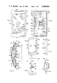
- FIG. 1 is a front elevational view showing an operative installation of the cover and actuator of this invention, partially in section to illustrate interior detail.
- FIG. 2 is a front elevational view of the device shown in FIG. 1 illustrating further interior details.
- FIG. 3 is a sectional view taken along line 3--3 of FIG. 1.
- FIG. 4 is a plan view of the frame member.
- FIG. 5 is a sectional view taken along line 5--5 of FIG. 4.
- FIG. 6 is a plan view of the switch actuator means.
- FIG. 7 is sectional view taken along line 7--7 of FIG. 6.
- FIG. 8 is a perspective view of a second embodiment of the switch actuator means.
- FIG. 9 is a perspective view, partially in section, similar to the view of FIG. 1.
- the wall switch cover actuator of this invention is generally indicated as 10 and is shown in the view of FIGS. 1, 2, and a in its normal, operative installation in combination with a standard wall toggle switch, generally indicated as 12.
- a standard wall toggle switch generally indicated as 12.
- the cover and actuator 12 is mounted in substantially surrounding, enclosing relation to wall switch 12, which is, in turn, mounted in switch aperture 14 formed through wall 16.
- wall toggle switch 12 is of standard construction and includes a switch box 18, a toggle arm 20, and a switch cover plate 22 held in position as by screws 24.
- cover and actuator 10 comprises a frame member defined by a base plate 26 having an aperture 28 formed therein.
- first and second frame side walls 30 and 32, respectively, extend transversely from base plate 26 and each define corresponding first and second arcuate top edges 34 and 36, respectively.
- the frame member further comprises opposed top and bottom frame lips 38 and 40 extending from base plate 26 in transverse relation between first side wall 30 and second side wall 32.
- top frame lip 38 and bottom frame lip 40 are substantially congruent with their corresponding segments of top edges 34 and 36. It is by virtue of this construction of the frame member that the cover and actuator 10 may be operatively installed simply by first removing screws 24 and switch cover plate 22. The frame member is then put into position and switch cover plate 22 is attached normally with its screws 24. Since the perimeter of switch cover plate 22 is larger than aperture 28 formed through base plate 26, the frame member is held securely against wall 16 and wall switch 12.
- Wall switch cover and actuator 10 further comprises the switch actuator means generally indicated as 42 in the views of FIGS. 6 and 7.
- Switch actuator means 42 is formed from flexible sheet material and comprises a main body 44 dimensioned and configured to fit within top frame lip 38 and bottom frame lip 40 to define an arcuate top surface corresponding substantially to the curved surface defined by first and second top edges 34 and 36.
- the switch actuator means 42 further comprises a first toggle finger 46 and a second toggle finger 48 defined by a pair of substantially parallel longitudinal slits 50 formed through main body 44 and a substantially bisecting transverse slit intersecting the pair of longitudinal slits 50.
- first toggle finger 46 and a corresponding segment 54 of second toggle finger 48 are each deformed downwardly with respect to the arcuate top surface of main body 44 in the direction of toggle arm 20.
- distal end 56 of first finger 46 is turned back upon itself to define a first shoulder 60.
- distal end 58 of second finger 48 is turned back upon itself to define a second shoulder 62.
- first shoulder 60 and second shoulder 62 actually define corresponding first and second cam surfaces with respect to first surface 64 and second surface 66 of toggle arm 20.
- cover sheet 68 which is removably held within the frame member by top frame lip 38 and bottom frame lip 40. It is, of course, the purpose of cover sheet 68 to enclose the front of wall switch cover and actuator 10 so as to present a finished, attractive appearance. Accordingly, cover sheet 68 may be formed from a flexible decorative material in accord with the user's desires. Alternatively, and as is illustrated in the preferred construction shown in the drawing figures, cover and actuator 10 utilizes a cover sheet 68 formed from a flexible, transparent material. Placed immediately behind cover sheet 68 is a decorative insert 70 which would therefore be visible through cover sheet 68.
- the preferred cover and actuator 10 also comprises a reinforcing insert 72 similarly mounted within the frame member and interposed between decorative insert 70 and main body 44 of the switch actuator means 42.
- a reinforcing insert 72 similarly mounted within the frame member and interposed between decorative insert 70 and main body 44 of the switch actuator means 42.
- segment 52 of first toggle finger 46 and corresponding segment 54 of second toggle finger 48 are permanently deformed as illustrated in FIGS. 3, 6 and 7, their flexibility and bias are retained. Thus, segments 52 and 54 actually respond much like "springs" to pressure applied against the face of cover sheet 68.
- a second embodiment for the switch actuator means of this invention is generally indicated as 74 in the view of FIG. 8.
- the width of the switch actuator means second embodiment 74 is substantially less than that of the preferred embodiment; however, its installation and operation is substantially equivalent.
- Second embodiment 74 of the switch actuator means is formed from flexible material having "memory" characteristics, and defines a first end 76 and a second end 78. Installation of second embodiment 74 is accomplished by inserting first end 76 within top frame lip 38 and inserting second end 78 within bottom frame lip 40.
- a toggle aperture 80 is formed substantially through the midpoint of second switch actuator means 74 such that toggle arm 20 may extend therethrough.
- first operating surface is defined by first semicircle 82
- second operating surface is defined by second semicircular segment 84. It is to be understood that first semicircular segment 82 is equivalent in function to first shoulder 60 and that second semicircular segment 84 is equivalent in function to second shoulder 62 of the preferred embodiment.
- second embodiment 74 of the switch actuator means further comprises a first fold 86 in spaced apart relation to first end 76 and a second fold 88 intermediate first fold 86 and first semicircular segment 82.
- second embodiment 74 further comprises a third fold 90 in spaced apart relation to second end 78 and a fourth fold 92 interposed between third fold 90 and second semicircular segment 84.
- switch actuator means 42 Because of the "memory" characteristics of the flexible material from which second embodiment 74 is formed, it may be substituted for switch actuator means 42 as, for example, in the operative installation depicted in the views of FIGS. 3 and 9.
- the angles defined at first fold 86 and third fold 90 are preferably greater than 90 so as to permit proper operation of the invention and to eliminate substantially the likelihood of second embodiment 74 collapsing upon itself.
Abstract
Description
______________________________________
       2,285,561
              2,382,738
       2,712,582
              3,004,128
       3,028,467
              3,188,438
       3,839,615
              3,892,935
       4,105,884
              4,234,774
______________________________________
Claims (11)
Priority Applications (1)
| Application Number | Priority Date | Filing Date | Title |
|---|---|---|---|
| US06/504,896 US4488024A (en) | 1983-06-16 | 1983-06-16 | Wall switch cover and actuator |
Applications Claiming Priority (1)
| Application Number | Priority Date | Filing Date | Title |
|---|---|---|---|
| US06/504,896 US4488024A (en) | 1983-06-16 | 1983-06-16 | Wall switch cover and actuator |
Publications (1)
| Publication Number | Publication Date |
|---|---|
| US4488024A true US4488024A (en) | 1984-12-11 |
Family
ID=24008166
Family Applications (1)
| Application Number | Title | Priority Date | Filing Date |
|---|---|---|---|
| US06/504,896 Expired - Fee Related US4488024A (en) | 1983-06-16 | 1983-06-16 | Wall switch cover and actuator |
Country Status (1)
| Country | Link |
|---|---|
| US (1) | US4488024A (en) |
Cited By (12)
| Publication number | Priority date | Publication date | Assignee | Title |
|---|---|---|---|---|
| US5446252A (en) * | 1994-01-21 | 1995-08-29 | Burger; Philip M. | Flat spring actuating mechanism for plunger-type switch |
| US5806665A (en) * | 1997-08-06 | 1998-09-15 | American Tack & Hardware Co., Inc. | Arcuate switch actuator |
| US5811729A (en) * | 1996-05-02 | 1998-09-22 | Rintz; William J. | Light switch cover |
| US5835980A (en) * | 1997-08-06 | 1998-11-10 | American Tack & Hardware Co, Inc. | Receptacle plate |
| US5874693A (en) * | 1996-05-02 | 1999-02-23 | Rintz; William J. | Light switch cover |
| US5883570A (en) * | 1997-05-06 | 1999-03-16 | Ed Ventions, Inc. | Decorative door bell actuator |
| US6046416A (en) * | 1996-12-13 | 2000-04-04 | King Of Fans, Inc. | Cover for ceiling fan reversing switch |
| US6051787A (en) * | 1996-05-02 | 2000-04-18 | Rintz; William J. | Light switch cover |
| US6982392B1 (en) | 2005-05-06 | 2006-01-03 | Burger & Brown Engineering, Inc. | Water resistant actuating mechanism for plunger type switches |
| US20080197009A1 (en) * | 2007-02-21 | 2008-08-21 | Burger & Brown Engineering, Inc. | Low-profile switch with flat spring actuating mechanism |
| US20110083948A1 (en) * | 2009-10-13 | 2011-04-14 | Michael Mahle | Switch conversion apparatus |
| USD775089S1 (en) * | 2015-02-14 | 2016-12-27 | iaconic Design Inc. | Wall-mounted lighting control |
Citations (4)
| Publication number | Priority date | Publication date | Assignee | Title |
|---|---|---|---|---|
| US1989393A (en) * | 1932-02-25 | 1935-01-29 | Appleton Electric Co | Switch enclosing box or housing |
| US3217112A (en) * | 1963-10-24 | 1965-11-09 | Stackpole Carbon Co | Rocker-actuated electric slide switch |
| US3668938A (en) * | 1971-03-01 | 1972-06-13 | Apm Corp | Hermetically sealing boot with actuator for thumb wheel type switches |
| US3932721A (en) * | 1975-02-03 | 1976-01-13 | Motorola, Inc. | Sealed switch actuator |
-
1983
- 1983-06-16 US US06/504,896 patent/US4488024A/en not_active Expired - Fee Related
Patent Citations (4)
| Publication number | Priority date | Publication date | Assignee | Title |
|---|---|---|---|---|
| US1989393A (en) * | 1932-02-25 | 1935-01-29 | Appleton Electric Co | Switch enclosing box or housing |
| US3217112A (en) * | 1963-10-24 | 1965-11-09 | Stackpole Carbon Co | Rocker-actuated electric slide switch |
| US3668938A (en) * | 1971-03-01 | 1972-06-13 | Apm Corp | Hermetically sealing boot with actuator for thumb wheel type switches |
| US3932721A (en) * | 1975-02-03 | 1976-01-13 | Motorola, Inc. | Sealed switch actuator |
Cited By (15)
| Publication number | Priority date | Publication date | Assignee | Title |
|---|---|---|---|---|
| US5446252A (en) * | 1994-01-21 | 1995-08-29 | Burger; Philip M. | Flat spring actuating mechanism for plunger-type switch |
| US6051787A (en) * | 1996-05-02 | 2000-04-18 | Rintz; William J. | Light switch cover |
| US5811729A (en) * | 1996-05-02 | 1998-09-22 | Rintz; William J. | Light switch cover |
| US5874693A (en) * | 1996-05-02 | 1999-02-23 | Rintz; William J. | Light switch cover |
| US6046416A (en) * | 1996-12-13 | 2000-04-04 | King Of Fans, Inc. | Cover for ceiling fan reversing switch |
| US5883570A (en) * | 1997-05-06 | 1999-03-16 | Ed Ventions, Inc. | Decorative door bell actuator |
| US5835980A (en) * | 1997-08-06 | 1998-11-10 | American Tack & Hardware Co, Inc. | Receptacle plate |
| US5806665A (en) * | 1997-08-06 | 1998-09-15 | American Tack & Hardware Co., Inc. | Arcuate switch actuator |
| US6982392B1 (en) | 2005-05-06 | 2006-01-03 | Burger & Brown Engineering, Inc. | Water resistant actuating mechanism for plunger type switches |
| US20080197009A1 (en) * | 2007-02-21 | 2008-08-21 | Burger & Brown Engineering, Inc. | Low-profile switch with flat spring actuating mechanism |
| US7569783B2 (en) | 2007-02-21 | 2009-08-04 | Burger & Brown Engineering, Inc. | Low-profile switch with flat spring actuating mechanism |
| US20110083948A1 (en) * | 2009-10-13 | 2011-04-14 | Michael Mahle | Switch conversion apparatus |
| US8796567B2 (en) | 2009-10-13 | 2014-08-05 | Michael Mahle | Switch conversion apparatus |
| US10121610B2 (en) | 2009-10-13 | 2018-11-06 | Effortless Systems, Llc | Switch conversion apparatus |
| USD775089S1 (en) * | 2015-02-14 | 2016-12-27 | iaconic Design Inc. | Wall-mounted lighting control |
Similar Documents
| Publication | Publication Date | Title |
|---|---|---|
| US4488024A (en) | Wall switch cover and actuator | |
| USD426292S (en) | Air conditioner | |
| US4628572A (en) | Clip structure | |
| KR20010096495A (en) | Ring binder having actuating lever with cushion member | |
| DK0761563T3 (en) | tablet dispenser | |
| CA2152732A1 (en) | Garment hanger assembly kit | |
| USD418368S (en) | Cup | |
| USD378552S (en) | Tote | |
| USD392175S (en) | Spring hinge | |
| CA1333272C (en) | Key ring | |
| US4427864A (en) | Electrical outlet switch | |
| USD359310S (en) | File folder | |
| US4991269A (en) | Clip | |
| US4880404A (en) | Puppet having sliding face panels defining a mouth opening | |
| US3066680A (en) | Ring binder | |
| GB2048665A (en) | Picture frame having integral latch means | |
| USD448523S1 (en) | Nail clipper | |
| US5596998A (en) | Hair clip | |
| USD450823S1 (en) | Air conditioner | |
| USD377208S (en) | Toilet seat assembly | |
| USD454188S1 (en) | Air conditioner | |
| USD449095S1 (en) | Air conditioner | |
| USD413924S (en) | Snap binder | |
| USD448799S1 (en) | Folder | |
| PT1608518E (en) | Clip for clipping sheets together |
Legal Events
| Date | Code | Title | Description |
|---|---|---|---|
| AS | Assignment |
Owner name: BUTLER, FREDERICK M., JR. 1315 NW 40TH TERRACE, GA Free format text: ASSIGNMENT OF ASSIGNORS INTEREST.;ASSIGNOR:COLGATE, SAMUEL O.;REEL/FRAME:004162/0213 Effective date: 19830607 Owner name: BUTLER, FREDERICK M., JR.,FLORIDA Free format text: ASSIGNMENT OF ASSIGNORS INTEREST;ASSIGNOR:COLGATE, SAMUEL O.;REEL/FRAME:004162/0213 Effective date: 19830607 |
|
| AS | Assignment |
Owner name: BUTLER, JOSEPHINE D., EXECUTRIX Free format text: LETTERS OF TESTAMENTARY;ASSIGNOR:COLGATE, SAMUEL O.;REEL/FRAME:004903/0940 Effective date: 19730309 |
|
| REMI | Maintenance fee reminder mailed | ||
| REIN | Reinstatement after maintenance fee payment confirmed | ||
| FP | Lapsed due to failure to pay maintenance fee |
Effective date: 19881211 |
|
| REMI | Maintenance fee reminder mailed | ||
| LAPS | Lapse for failure to pay maintenance fees | ||
| FP | Lapsed due to failure to pay maintenance fee |
Effective date: 19921213 |
|
| STCH | Information on status: patent discontinuation |
Free format text: PATENT EXPIRED DUE TO NONPAYMENT OF MAINTENANCE FEES UNDER 37 CFR 1.362 |