US4461974A - Dual light source - Google Patents
Dual light source Download PDFInfo
- Publication number
- US4461974A US4461974A US06/386,736 US38673682A US4461974A US 4461974 A US4461974 A US 4461974A US 38673682 A US38673682 A US 38673682A US 4461974 A US4461974 A US 4461974A
- Authority
- US
- United States
- Prior art keywords
- lamp
- light
- circuit
- light guide
- switch
- Prior art date
- Legal status (The legal status is an assumption and is not a legal conclusion. Google has not performed a legal analysis and makes no representation as to the accuracy of the status listed.)
- Expired - Fee Related
Links
Images
Classifications
-
- H—ELECTRICITY
- H05—ELECTRIC TECHNIQUES NOT OTHERWISE PROVIDED FOR
- H05B—ELECTRIC HEATING; ELECTRIC LIGHT SOURCES NOT OTHERWISE PROVIDED FOR; CIRCUIT ARRANGEMENTS FOR ELECTRIC LIGHT SOURCES, IN GENERAL
- H05B47/00—Circuit arrangements for operating light sources in general, i.e. where the type of light source is not relevant
- H05B47/20—Responsive to malfunctions or to light source life; for protection
- H05B47/29—Circuits providing for substitution of the light source in case of its failure
Definitions
- This invention relates to a dual light source, and more particularly to a system for automatically switching lamps in a fiber optic delivery system when the lamp being used fails in service.
- Fiber optic systems for the delivery of light from a source into otherwise inaccessible locations have won widespread acceptance in a variety of situations, including their application to medical technology.
- the problems and drawbacks of existing systems for switching light bulbs in fiber optic light delivery systems are overcome by providing a simple system of optically combining two light sources into one fiber optic bundle, one of which is standby while the other is operating. In the event of failure of the primary source, automatic switching takes place so that there is no significant interruption in light.
- a fiber optic light guide with an entrance for light, a pair of lamps directing the light into the entrance of the guide, both within the angle of acceptance of the guide, and an electrical circuit for delivering current to the lamps to effect this operation.
- both lamps are identical, one is the main lamp, and the other is a standby lamp which becomes energized upon the failure of the main lamp. This is accomplished by connecting the lamps in parallel within said electrical circuit.
- a solenoid is provided in which the coil is located within the main lamp part of the circuit, while the solenoid actuated switch is in the standby lamp part of the circuit.
- the switch is biased into its closed position and held open by energization of the solenoid coil.
- the solenoid is deenergized, the switch closes, and the standby lamp becomes energized and begins to direct light into the entrance to the light guide. This switchover is accomplished rapidly with barely any detectable interruption of light.
- a further object of this invention is to provide a dual lamp illuminating system for use with a fiber optic light guide capable of switching from one lamp to another efficiently and reliably in the event of failure of the operating lamp.
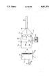
- FIGURE illustrates schematically a preferred embodiment of this invention.
- a light guide 12 which has an entrance 14 for light.
- guide 12 would be a fiber optic cable consisting of a bundle of glass filaments as is currently well known in the art.
- a fiber optic cable has an angle of acceptance in which it can accept the light for transmittal efficiently and effectively.
- a typical such angle of acceptance is 60 degrees.
- a pair of lamps L1 and L2, main and standby, respectively, are mounted as illustrated to focus and direct their light at entrance 14 of cable 12 within the angle of acceptance of the cable entrance.
- Lamps L1 and L2 illustrated are filament type but, of course, any other variety of electrically powered lamps may be employed.
- a source of electrical energy of energize lamps L1 and L2 is provided by way of a connector plug 15, electrical conductors 16 and 18, and a transformer T.
- a transformer T In the primary circuit of the latter are provided an on-off switch S1 and a fuse or circuit breaker F1.
- a tap from transformer T by conductor 22 and conductor 18 deliver the electric supply to lamps L1 and L2 which are connected in parallel. It will be seen that main lamp L1 is supplied by conductors 24 and 26 while standby lamp L2 is supplied by conductors 18 and 28.
- a solenoid 30 consisting of an inductor or coil I, and a switch S2 rendered operative by coil I is provided with coil I in conductor 24 to lamp L1 and switch S2 in conductor 28 to lamp L2.
- Switch S2 is biased in its closed position but is held open by coil I when the latter is energized.
- An indicator 32 which could be a lamp or a buzzer, is connected across conductors 18 and 28.
- conductor 24 is also provided a fuse or circuit breaker F2.
- switch S2 will also cause indicator 28 to operate, and the signal it emits, such as a lighted lamp or a buzz, will indicate that main lamp L1 has failed.
- a feature of this invention is that failed lamp L1 can be changed without interrupting light delivered to cable 12, at the same time returning lamp L2 to its standby service.
- Another advantage of this invention results from angling the light into the entrance of the fiber optic cable. If light from a conventional quartz halogen lamp is fed on axis, a dark shadow appears at the output of the cable. This is caused by the image of the filament. By angling the light, the filament image is diffused and does not appear at the cable output.
- An important feature of this invention is that failure of the main lamp, regardless whether due to an open filament or a short circuit, will automatically bring the standby lamp into operation.
Abstract
Description
Claims (5)
Priority Applications (1)
| Application Number | Priority Date | Filing Date | Title |
|---|---|---|---|
| US06/386,736 US4461974A (en) | 1982-06-09 | 1982-06-09 | Dual light source |
Applications Claiming Priority (1)
| Application Number | Priority Date | Filing Date | Title |
|---|---|---|---|
| US06/386,736 US4461974A (en) | 1982-06-09 | 1982-06-09 | Dual light source |
Publications (1)
| Publication Number | Publication Date |
|---|---|
| US4461974A true US4461974A (en) | 1984-07-24 |
Family
ID=23526843
Family Applications (1)
| Application Number | Title | Priority Date | Filing Date |
|---|---|---|---|
| US06/386,736 Expired - Fee Related US4461974A (en) | 1982-06-09 | 1982-06-09 | Dual light source |
Country Status (1)
| Country | Link |
|---|---|
| US (1) | US4461974A (en) |
Cited By (24)
| Publication number | Priority date | Publication date | Assignee | Title |
|---|---|---|---|---|
| US4539625A (en) * | 1984-07-31 | 1985-09-03 | Dhr, Incorporated | Lighting system combining daylight concentrators and an artificial source |
| US4631649A (en) * | 1985-10-16 | 1986-12-23 | Chloride Systems, a division of Chloride Power Electronics, Incorporated | Plug-in emergency light fixture |
| US4708223A (en) * | 1986-09-29 | 1987-11-24 | Westinghouse Electric Corp. | Emergency lighting for elevator cab |
| US4712051A (en) * | 1986-06-02 | 1987-12-08 | Ultima Electronics Ltd. | Adapter for switching from primary to standby device upon failure of primary device |
| US4734625A (en) * | 1984-10-18 | 1988-03-29 | American Sterilizer Company | Control circuit for system for controlling the operation of electric lights |
| US4767968A (en) * | 1984-10-18 | 1988-08-30 | American Sterilizer Company | System for controlling the operation of electrically powered apparatus |
| US4768133A (en) * | 1986-02-13 | 1988-08-30 | Thorn Emi Plc | Lighting device |
| US4782429A (en) * | 1987-04-10 | 1988-11-01 | Walton John F | Long-life luminaires |
| US4961028A (en) * | 1987-12-07 | 1990-10-02 | Hayashi Tokei Kogyo Kabushiki Kaisha | Lighting equipment |
| EP0394099A1 (en) * | 1989-04-20 | 1990-10-24 | SOCIETE D'ETUDES POUR LE DEVELOPPEMENT DES PRODUCTIONS ELECTRONIQUES société anonyme | Lighting device for an optical fibre bundle |
| US5012157A (en) * | 1987-04-10 | 1991-04-30 | Walton John F | Long-life luminaires |
| US5022613A (en) * | 1990-04-26 | 1991-06-11 | Safetran Systems Corporation | AC and battery backup supply for a railroad crossing gate |
| US5025349A (en) * | 1988-09-08 | 1991-06-18 | Gow Thomas W | Emergency lighting fixture |
| US5404002A (en) * | 1993-05-17 | 1995-04-04 | At&T Global Information Solutions Company | Backup method for multiple source optical scanner |
| US5552590A (en) * | 1992-09-08 | 1996-09-03 | Nippondenso Co., Ltd. | Optical information reading apparatus having means for judging laser deterioration |
| US5682131A (en) * | 1996-04-04 | 1997-10-28 | Gow; Thomas W. | Retractable tamper resistant annunciator |
| US5833350A (en) * | 1997-04-25 | 1998-11-10 | Electro Static Solutions, Llc | Switch cover plate providing automatic emergency lighting |
| WO2000050810A1 (en) | 1999-02-26 | 2000-08-31 | Moreland Gregory B | Switch cover plate providing automatic emergency lighting |
| US20020025114A1 (en) * | 2000-04-17 | 2002-02-28 | Vertical Computer Systems, Inc. | Apparatus and method for transmitting images over a single-filament fiber optic cable |
| US6494899B1 (en) | 1999-01-22 | 2002-12-17 | Respironics, Inc. | Phototherapy system and method |
| US7083315B2 (en) | 2001-03-26 | 2006-08-01 | Siemens Airfield Solutions | Elevated airfield runway and taxiway edge-lights utilizing light emitting diodes |
| US20070133227A1 (en) * | 2005-12-12 | 2007-06-14 | Au Optronics Corporation | Backlight module |
| US20080297053A1 (en) * | 2007-05-28 | 2008-12-04 | Young Optics Inc. | Method for controlling dual lamp module |
| US10483706B2 (en) | 2017-01-20 | 2019-11-19 | Automatic Switch Company | Solenoid coil with replaceable status indicator light |
Citations (5)
| Publication number | Priority date | Publication date | Assignee | Title |
|---|---|---|---|---|
| US2735928A (en) * | 1956-02-21 | Emergency lamp | ||
| US3327162A (en) * | 1962-07-05 | 1967-06-20 | Ass Elect Ind | Optical projection systems |
| US3541341A (en) * | 1968-02-21 | 1970-11-17 | Gen Electric | Redundant fiber-optic light guide construction |
| US4048486A (en) * | 1974-11-22 | 1977-09-13 | Jenaer Glaswerk, Schott & Gen. | Lighting device for fiber-optic systems |
| US4399358A (en) * | 1979-11-02 | 1983-08-16 | Dr. Johannes Heidenhain Gmbh | Photoelectric digital measuring instrument having multiple light sources |
-
1982
- 1982-06-09 US US06/386,736 patent/US4461974A/en not_active Expired - Fee Related
Patent Citations (5)
| Publication number | Priority date | Publication date | Assignee | Title |
|---|---|---|---|---|
| US2735928A (en) * | 1956-02-21 | Emergency lamp | ||
| US3327162A (en) * | 1962-07-05 | 1967-06-20 | Ass Elect Ind | Optical projection systems |
| US3541341A (en) * | 1968-02-21 | 1970-11-17 | Gen Electric | Redundant fiber-optic light guide construction |
| US4048486A (en) * | 1974-11-22 | 1977-09-13 | Jenaer Glaswerk, Schott & Gen. | Lighting device for fiber-optic systems |
| US4399358A (en) * | 1979-11-02 | 1983-08-16 | Dr. Johannes Heidenhain Gmbh | Photoelectric digital measuring instrument having multiple light sources |
Non-Patent Citations (4)
| Title |
|---|
| "Coupling Light-Sources to Fibers," by Mark L. Dakss, Laser Focus, Dec. 1975, pp. 31-34. |
| "Speroid Lens at Fiber End" by O. R. Gupta, IBM Tech. Disc. Bull., vol. 24, No. 2, Jul. 1981, pp. 1161, 1162. |
| Coupling Light Sources to Fibers, by Mark L. Dakss, Laser Focus, Dec. 1975, pp. 31 34. * |
| Speroid Lens at Fiber End by O. R. Gupta, IBM Tech. Disc. Bull., vol. 24, No. 2, Jul. 1981, pp. 1161, 1162. * |
Cited By (34)
| Publication number | Priority date | Publication date | Assignee | Title |
|---|---|---|---|---|
| US4539625A (en) * | 1984-07-31 | 1985-09-03 | Dhr, Incorporated | Lighting system combining daylight concentrators and an artificial source |
| US4767968A (en) * | 1984-10-18 | 1988-08-30 | American Sterilizer Company | System for controlling the operation of electrically powered apparatus |
| US4734625A (en) * | 1984-10-18 | 1988-03-29 | American Sterilizer Company | Control circuit for system for controlling the operation of electric lights |
| US4631649A (en) * | 1985-10-16 | 1986-12-23 | Chloride Systems, a division of Chloride Power Electronics, Incorporated | Plug-in emergency light fixture |
| US4768133A (en) * | 1986-02-13 | 1988-08-30 | Thorn Emi Plc | Lighting device |
| US4712051A (en) * | 1986-06-02 | 1987-12-08 | Ultima Electronics Ltd. | Adapter for switching from primary to standby device upon failure of primary device |
| US4708223A (en) * | 1986-09-29 | 1987-11-24 | Westinghouse Electric Corp. | Emergency lighting for elevator cab |
| US4782429A (en) * | 1987-04-10 | 1988-11-01 | Walton John F | Long-life luminaires |
| US5012157A (en) * | 1987-04-10 | 1991-04-30 | Walton John F | Long-life luminaires |
| US4961028A (en) * | 1987-12-07 | 1990-10-02 | Hayashi Tokei Kogyo Kabushiki Kaisha | Lighting equipment |
| US5025349A (en) * | 1988-09-08 | 1991-06-18 | Gow Thomas W | Emergency lighting fixture |
| EP0394099A1 (en) * | 1989-04-20 | 1990-10-24 | SOCIETE D'ETUDES POUR LE DEVELOPPEMENT DES PRODUCTIONS ELECTRONIQUES société anonyme | Lighting device for an optical fibre bundle |
| FR2646227A1 (en) * | 1989-04-20 | 1990-10-26 | Soc Et Dev Prod Electron | ILLUMINATION DEVICE FOR A BEAM OF OPTICAL FIBERS |
| US5053929A (en) * | 1989-04-20 | 1991-10-01 | Societe D'etudes Pour Le Developpement Des Productions Electroniques | Device for illuminating a bundle of optical fibers |
| US5022613A (en) * | 1990-04-26 | 1991-06-11 | Safetran Systems Corporation | AC and battery backup supply for a railroad crossing gate |
| US5552590A (en) * | 1992-09-08 | 1996-09-03 | Nippondenso Co., Ltd. | Optical information reading apparatus having means for judging laser deterioration |
| US5404002A (en) * | 1993-05-17 | 1995-04-04 | At&T Global Information Solutions Company | Backup method for multiple source optical scanner |
| US5682131A (en) * | 1996-04-04 | 1997-10-28 | Gow; Thomas W. | Retractable tamper resistant annunciator |
| US5833350A (en) * | 1997-04-25 | 1998-11-10 | Electro Static Solutions, Llc | Switch cover plate providing automatic emergency lighting |
| US6000807A (en) * | 1997-04-25 | 1999-12-14 | Moreland; Gregory B. | Switch cover plate providing automatic emergency lighting |
| US6494899B1 (en) | 1999-01-22 | 2002-12-17 | Respironics, Inc. | Phototherapy system and method |
| WO2000050810A1 (en) | 1999-02-26 | 2000-08-31 | Moreland Gregory B | Switch cover plate providing automatic emergency lighting |
| US20040190843A1 (en) * | 2000-04-17 | 2004-09-30 | Cruz Aluizio M. | Apparatus and method for transmitting images over a single-filament fiber optic cable |
| US20020025114A1 (en) * | 2000-04-17 | 2002-02-28 | Vertical Computer Systems, Inc. | Apparatus and method for transmitting images over a single-filament fiber optic cable |
| US6718103B2 (en) | 2000-04-17 | 2004-04-06 | Vertical Computer Systems, Inc. | Apparatus and method for transmitting images over a single-filament fiber optic cable |
| US7083315B2 (en) | 2001-03-26 | 2006-08-01 | Siemens Airfield Solutions | Elevated airfield runway and taxiway edge-lights utilizing light emitting diodes |
| WO2002103410A3 (en) * | 2001-06-18 | 2004-01-22 | Vertical Comp Systems Inc | Apparatus and method for transmitting images over a single-filament fiber optic cable |
| WO2002103410A2 (en) * | 2001-06-18 | 2002-12-27 | Vertical Computer Systems, Inc. | Apparatus and method for transmitting images over a single-filament fiber optic cable |
| US20070133227A1 (en) * | 2005-12-12 | 2007-06-14 | Au Optronics Corporation | Backlight module |
| US8002453B2 (en) * | 2005-12-12 | 2011-08-23 | Au Optronics Corporation | Light-emitting diode backlight module and liquid crystal display using the same |
| US20080297053A1 (en) * | 2007-05-28 | 2008-12-04 | Young Optics Inc. | Method for controlling dual lamp module |
| US7824038B2 (en) | 2007-05-28 | 2010-11-02 | Young Optics Inc. | Method for controlling dual lamp module |
| US10483706B2 (en) | 2017-01-20 | 2019-11-19 | Automatic Switch Company | Solenoid coil with replaceable status indicator light |
| US11437769B2 (en) | 2017-01-20 | 2022-09-06 | Automatic Switch Company | Solenoid coil with replaceable status indicator light |
Similar Documents
| Publication | Publication Date | Title |
|---|---|---|
| US4461974A (en) | Dual light source | |
| US4356534A (en) | Light supply device for an endoscope | |
| US4433675A (en) | Light supply apparatus for endoscope | |
| US4144462A (en) | Emergency lighting fluorescent pack | |
| US5323116A (en) | Test device for testing compact fluorescent lights and ballasts | |
| US5053929A (en) | Device for illuminating a bundle of optical fibers | |
| US2883652A (en) | Combination pushbutton control and multiple indicator | |
| US4579419A (en) | Fiber optic connector and apparatus and method employing same | |
| JPS6153050B2 (en) | ||
| US5406461A (en) | Illumination system for optical equipment with separate illuminating beam paths | |
| US4286196A (en) | Automatic dimmer cutout for arc lamp of fiber optic light source | |
| US1918480A (en) | Light signal | |
| SU951760A1 (en) | Device for incandescent lamp power supply | |
| EP0302737A2 (en) | Multi-bulb light source | |
| JPH0266892A (en) | Lamp failure sensor circuit and lamp changeover device | |
| US2132097A (en) | Flashing light signal | |
| JPH0266891A (en) | Lamp blowoff sensor circuit | |
| CS58482A2 (en) | Elektricka osvetlovaci jednotka | |
| JPH01284822A (en) | Light source unit for endoscope | |
| JPH0327882B2 (en) | ||
| US2864005A (en) | Standby electrical system | |
| JPS5830094A (en) | Core breakage detecting and fail-safe device wick | |
| JPS6345569B2 (en) | ||
| US2187018A (en) | Automatic light-selector system | |
| JPH06203976A (en) | Discharge lamp lighting device and lighting system |
Legal Events
| Date | Code | Title | Description |
|---|---|---|---|
| FEPP | Fee payment procedure |
Free format text: PAYOR NUMBER ASSIGNED (ORIGINAL EVENT CODE: ASPN); ENTITY STATUS OF PATENT OWNER: SMALL ENTITY |
|
| FEPP | Fee payment procedure |
Free format text: PAYOR NUMBER ASSIGNED (ORIGINAL EVENT CODE: ASPN); ENTITY STATUS OF PATENT OWNER: SMALL ENTITY Free format text: PAYER NUMBER DE-ASSIGNED (ORIGINAL EVENT CODE: RMPN); ENTITY STATUS OF PATENT OWNER: SMALL ENTITY |
|
| FPAY | Fee payment |
Year of fee payment: 4 |
|
| FPAY | Fee payment |
Year of fee payment: 8 |
|
| REMI | Maintenance fee reminder mailed | ||
| LAPS | Lapse for failure to pay maintenance fees | ||
| FP | Lapsed due to failure to pay maintenance fee |
Effective date: 19960724 |
|
| STCH | Information on status: patent discontinuation |
Free format text: PATENT EXPIRED DUE TO NONPAYMENT OF MAINTENANCE FEES UNDER 37 CFR 1.362 |