US4450472A - Method and means for improved heat removal in compact semiconductor integrated circuits and similar devices utilizing coolant chambers and microscopic channels - Google Patents
Method and means for improved heat removal in compact semiconductor integrated circuits and similar devices utilizing coolant chambers and microscopic channels Download PDFInfo
- Publication number
- US4450472A US4450472A US06/239,407 US23940781A US4450472A US 4450472 A US4450472 A US 4450472A US 23940781 A US23940781 A US 23940781A US 4450472 A US4450472 A US 4450472A
- Authority
- US
- United States
- Prior art keywords
- coolant
- channels
- fins
- integrated circuit
- semiconductor integrated
- Prior art date
- Legal status (The legal status is an assumption and is not a legal conclusion. Google has not performed a legal analysis and makes no representation as to the accuracy of the status listed.)
- Expired - Fee Related
Links
Images


Classifications
-
- F—MECHANICAL ENGINEERING; LIGHTING; HEATING; WEAPONS; BLASTING
- F28—HEAT EXCHANGE IN GENERAL
- F28D—HEAT-EXCHANGE APPARATUS, NOT PROVIDED FOR IN ANOTHER SUBCLASS, IN WHICH THE HEAT-EXCHANGE MEDIA DO NOT COME INTO DIRECT CONTACT
- F28D15/00—Heat-exchange apparatus with the intermediate heat-transfer medium in closed tubes passing into or through the conduit walls ; Heat-exchange apparatus employing intermediate heat-transfer medium or bodies
- F28D15/02—Heat-exchange apparatus with the intermediate heat-transfer medium in closed tubes passing into or through the conduit walls ; Heat-exchange apparatus employing intermediate heat-transfer medium or bodies in which the medium condenses and evaporates, e.g. heat pipes
- F28D15/04—Heat-exchange apparatus with the intermediate heat-transfer medium in closed tubes passing into or through the conduit walls ; Heat-exchange apparatus employing intermediate heat-transfer medium or bodies in which the medium condenses and evaporates, e.g. heat pipes with tubes having a capillary structure
- F28D15/046—Heat-exchange apparatus with the intermediate heat-transfer medium in closed tubes passing into or through the conduit walls ; Heat-exchange apparatus employing intermediate heat-transfer medium or bodies in which the medium condenses and evaporates, e.g. heat pipes with tubes having a capillary structure characterised by the material or the construction of the capillary structure
-
- H—ELECTRICITY
- H01—ELECTRIC ELEMENTS
- H01L—SEMICONDUCTOR DEVICES NOT COVERED BY CLASS H10
- H01L23/00—Details of semiconductor or other solid state devices
- H01L23/34—Arrangements for cooling, heating, ventilating or temperature compensation ; Temperature sensing arrangements
- H01L23/46—Arrangements for cooling, heating, ventilating or temperature compensation ; Temperature sensing arrangements involving the transfer of heat by flowing fluids
- H01L23/473—Arrangements for cooling, heating, ventilating or temperature compensation ; Temperature sensing arrangements involving the transfer of heat by flowing fluids by flowing liquids
-
- H—ELECTRICITY
- H01—ELECTRIC ELEMENTS
- H01L—SEMICONDUCTOR DEVICES NOT COVERED BY CLASS H10
- H01L24/00—Arrangements for connecting or disconnecting semiconductor or solid-state bodies; Methods or apparatus related thereto
- H01L24/01—Means for bonding being attached to, or being formed on, the surface to be connected, e.g. chip-to-package, die-attach, "first-level" interconnects; Manufacturing methods related thereto
- H01L24/26—Layer connectors, e.g. plate connectors, solder or adhesive layers; Manufacturing methods related thereto
- H01L24/31—Structure, shape, material or disposition of the layer connectors after the connecting process
- H01L24/32—Structure, shape, material or disposition of the layer connectors after the connecting process of an individual layer connector
-
- H—ELECTRICITY
- H01—ELECTRIC ELEMENTS
- H01L—SEMICONDUCTOR DEVICES NOT COVERED BY CLASS H10
- H01L2224/00—Indexing scheme for arrangements for connecting or disconnecting semiconductor or solid-state bodies and methods related thereto as covered by H01L24/00
- H01L2224/01—Means for bonding being attached to, or being formed on, the surface to be connected, e.g. chip-to-package, die-attach, "first-level" interconnects; Manufacturing methods related thereto
- H01L2224/42—Wire connectors; Manufacturing methods related thereto
- H01L2224/47—Structure, shape, material or disposition of the wire connectors after the connecting process
- H01L2224/48—Structure, shape, material or disposition of the wire connectors after the connecting process of an individual wire connector
- H01L2224/4805—Shape
- H01L2224/4809—Loop shape
- H01L2224/48091—Arched
-
- H—ELECTRICITY
- H01—ELECTRIC ELEMENTS
- H01L—SEMICONDUCTOR DEVICES NOT COVERED BY CLASS H10
- H01L2224/00—Indexing scheme for arrangements for connecting or disconnecting semiconductor or solid-state bodies and methods related thereto as covered by H01L24/00
- H01L2224/01—Means for bonding being attached to, or being formed on, the surface to be connected, e.g. chip-to-package, die-attach, "first-level" interconnects; Manufacturing methods related thereto
- H01L2224/42—Wire connectors; Manufacturing methods related thereto
- H01L2224/47—Structure, shape, material or disposition of the wire connectors after the connecting process
- H01L2224/48—Structure, shape, material or disposition of the wire connectors after the connecting process of an individual wire connector
- H01L2224/481—Disposition
- H01L2224/48151—Connecting between a semiconductor or solid-state body and an item not being a semiconductor or solid-state body, e.g. chip-to-substrate, chip-to-passive
- H01L2224/48221—Connecting between a semiconductor or solid-state body and an item not being a semiconductor or solid-state body, e.g. chip-to-substrate, chip-to-passive the body and the item being stacked
- H01L2224/48225—Connecting between a semiconductor or solid-state body and an item not being a semiconductor or solid-state body, e.g. chip-to-substrate, chip-to-passive the body and the item being stacked the item being non-metallic, e.g. insulating substrate with or without metallisation
- H01L2224/48227—Connecting between a semiconductor or solid-state body and an item not being a semiconductor or solid-state body, e.g. chip-to-substrate, chip-to-passive the body and the item being stacked the item being non-metallic, e.g. insulating substrate with or without metallisation connecting the wire to a bond pad of the item
-
- H—ELECTRICITY
- H01—ELECTRIC ELEMENTS
- H01L—SEMICONDUCTOR DEVICES NOT COVERED BY CLASS H10
- H01L2224/00—Indexing scheme for arrangements for connecting or disconnecting semiconductor or solid-state bodies and methods related thereto as covered by H01L24/00
- H01L2224/01—Means for bonding being attached to, or being formed on, the surface to be connected, e.g. chip-to-package, die-attach, "first-level" interconnects; Manufacturing methods related thereto
- H01L2224/42—Wire connectors; Manufacturing methods related thereto
- H01L2224/47—Structure, shape, material or disposition of the wire connectors after the connecting process
- H01L2224/49—Structure, shape, material or disposition of the wire connectors after the connecting process of a plurality of wire connectors
- H01L2224/491—Disposition
- H01L2224/4912—Layout
- H01L2224/49171—Fan-out arrangements
-
- H—ELECTRICITY
- H01—ELECTRIC ELEMENTS
- H01L—SEMICONDUCTOR DEVICES NOT COVERED BY CLASS H10
- H01L2224/00—Indexing scheme for arrangements for connecting or disconnecting semiconductor or solid-state bodies and methods related thereto as covered by H01L24/00
- H01L2224/73—Means for bonding being of different types provided for in two or more of groups H01L2224/10, H01L2224/18, H01L2224/26, H01L2224/34, H01L2224/42, H01L2224/50, H01L2224/63, H01L2224/71
- H01L2224/732—Location after the connecting process
- H01L2224/73251—Location after the connecting process on different surfaces
- H01L2224/73265—Layer and wire connectors
-
- H—ELECTRICITY
- H01—ELECTRIC ELEMENTS
- H01L—SEMICONDUCTOR DEVICES NOT COVERED BY CLASS H10
- H01L24/00—Arrangements for connecting or disconnecting semiconductor or solid-state bodies; Methods or apparatus related thereto
- H01L24/01—Means for bonding being attached to, or being formed on, the surface to be connected, e.g. chip-to-package, die-attach, "first-level" interconnects; Manufacturing methods related thereto
- H01L24/42—Wire connectors; Manufacturing methods related thereto
- H01L24/47—Structure, shape, material or disposition of the wire connectors after the connecting process
- H01L24/48—Structure, shape, material or disposition of the wire connectors after the connecting process of an individual wire connector
-
- H—ELECTRICITY
- H01—ELECTRIC ELEMENTS
- H01L—SEMICONDUCTOR DEVICES NOT COVERED BY CLASS H10
- H01L24/00—Arrangements for connecting or disconnecting semiconductor or solid-state bodies; Methods or apparatus related thereto
- H01L24/01—Means for bonding being attached to, or being formed on, the surface to be connected, e.g. chip-to-package, die-attach, "first-level" interconnects; Manufacturing methods related thereto
- H01L24/42—Wire connectors; Manufacturing methods related thereto
- H01L24/47—Structure, shape, material or disposition of the wire connectors after the connecting process
- H01L24/49—Structure, shape, material or disposition of the wire connectors after the connecting process of a plurality of wire connectors
-
- H—ELECTRICITY
- H01—ELECTRIC ELEMENTS
- H01L—SEMICONDUCTOR DEVICES NOT COVERED BY CLASS H10
- H01L2924/00—Indexing scheme for arrangements or methods for connecting or disconnecting semiconductor or solid-state bodies as covered by H01L24/00
- H01L2924/0001—Technical content checked by a classifier
- H01L2924/00014—Technical content checked by a classifier the subject-matter covered by the group, the symbol of which is combined with the symbol of this group, being disclosed without further technical details
-
- H—ELECTRICITY
- H01—ELECTRIC ELEMENTS
- H01L—SEMICONDUCTOR DEVICES NOT COVERED BY CLASS H10
- H01L2924/00—Indexing scheme for arrangements or methods for connecting or disconnecting semiconductor or solid-state bodies as covered by H01L24/00
- H01L2924/01—Chemical elements
- H01L2924/01014—Silicon [Si]
-
- H—ELECTRICITY
- H01—ELECTRIC ELEMENTS
- H01L—SEMICONDUCTOR DEVICES NOT COVERED BY CLASS H10
- H01L2924/00—Indexing scheme for arrangements or methods for connecting or disconnecting semiconductor or solid-state bodies as covered by H01L24/00
- H01L2924/01—Chemical elements
- H01L2924/01019—Potassium [K]
-
- H—ELECTRICITY
- H01—ELECTRIC ELEMENTS
- H01L—SEMICONDUCTOR DEVICES NOT COVERED BY CLASS H10
- H01L2924/00—Indexing scheme for arrangements or methods for connecting or disconnecting semiconductor or solid-state bodies as covered by H01L24/00
- H01L2924/10—Details of semiconductor or other solid state devices to be connected
- H01L2924/1015—Shape
- H01L2924/10155—Shape being other than a cuboid
- H01L2924/10158—Shape being other than a cuboid at the passive surface
-
- H—ELECTRICITY
- H01—ELECTRIC ELEMENTS
- H01L—SEMICONDUCTOR DEVICES NOT COVERED BY CLASS H10
- H01L2924/00—Indexing scheme for arrangements or methods for connecting or disconnecting semiconductor or solid-state bodies as covered by H01L24/00
- H01L2924/10—Details of semiconductor or other solid state devices to be connected
- H01L2924/11—Device type
- H01L2924/12—Passive devices, e.g. 2 terminal devices
- H01L2924/1204—Optical Diode
- H01L2924/12041—LED
-
- H—ELECTRICITY
- H01—ELECTRIC ELEMENTS
- H01L—SEMICONDUCTOR DEVICES NOT COVERED BY CLASS H10
- H01L2924/00—Indexing scheme for arrangements or methods for connecting or disconnecting semiconductor or solid-state bodies as covered by H01L24/00
- H01L2924/10—Details of semiconductor or other solid state devices to be connected
- H01L2924/11—Device type
- H01L2924/12—Passive devices, e.g. 2 terminal devices
- H01L2924/1204—Optical Diode
- H01L2924/12042—LASER
-
- H—ELECTRICITY
- H01—ELECTRIC ELEMENTS
- H01L—SEMICONDUCTOR DEVICES NOT COVERED BY CLASS H10
- H01L2924/00—Indexing scheme for arrangements or methods for connecting or disconnecting semiconductor or solid-state bodies as covered by H01L24/00
- H01L2924/10—Details of semiconductor or other solid state devices to be connected
- H01L2924/11—Device type
- H01L2924/14—Integrated circuits
-
- H—ELECTRICITY
- H01—ELECTRIC ELEMENTS
- H01L—SEMICONDUCTOR DEVICES NOT COVERED BY CLASS H10
- H01L2924/00—Indexing scheme for arrangements or methods for connecting or disconnecting semiconductor or solid-state bodies as covered by H01L24/00
- H01L2924/15—Details of package parts other than the semiconductor or other solid state devices to be connected
- H01L2924/161—Cap
- H01L2924/1615—Shape
- H01L2924/16195—Flat cap [not enclosing an internal cavity]
Definitions
- This invention relates generally to heat generating devices, and more particularly the invention relates to compact devices such as semiconductor integrated circuits and a method and means for removal of heat from such devices.
- VLSI very large scale integrated circuit arrays
- heat conducting pedestals have been mounted on semiconductor chips and packages for heat removal to an air or fluid coolant.
- Proposals have been suggested for engaging the semiconductor chips directly with the coolant.
- An object of the present invention is an improved method of removing heat from a heat generating device.
- Another object of the invention is a compact heat dissipating structure having low thermal resistance.
- Another object of the invention is a semiconductor integrated circuit having improved power dissipation capability.
- Yet another object of the invention is a compact heat dissipation assembly.
- Still another object of the invention is a semiconductor integrated circuit and package which incorporates heat removal structure with electrical power busses.
- a feature of the invention is the use of microscopic heat conducting fins in intimate contact with a semiconductor chip for defining constricted channels.
- Another feature of the invention is the use of laminar coolant flow for removing heat from a semiconductor chip.
- microscopic heat fins are provided in integral contact with a heat generating device such as a chip and a coolant engages the fins in laminar flow for heat removal.
- a heat generating device such as a chip
- a coolant engages the fins in laminar flow for heat removal.
- the physical dimensions of the fins and channels are optimized for the particular material and coolant employed.
- the back surface of a semiconductor chip includes a recessed portion with heat conducting fins rising from the recessed portion.
- a planar member engages the back surface and the tops of the fins to define a coolant chamber.
- a coolant input line and a coolant output line communicate the coolant to and from the chamber whereby the coolant flows laminarly in constricted channels between the fins.
- the back surface of a semiconductor chip includes heat conducting fins which extend across the chip.
- the chip is mounted in a package having coolant input and output tubes whereby coolant flows in constricted channels within the back surface of the chip.
- the input and output tubes can function as power busses to the chip.
- FIG. 1 is a rear view of a semiconductor integrated circuit chip in accordance with one embodiment of the invention.
- FIG. 2 is a sectional view of the chip of FIG. 1 taken along the line 2--2.
- FIG. 3 is an enlarged perspective view of a portion of a semiconductor integrated circuit chip of FIG. 1.
- FIG. 4 is a perspective view of a semiconductor integrated circuit chip in accordance with another embodiment of the invention.
- FIG. 5 is a front view of a semiconductor integrated circuit chip and package in accordance wlith another embodiment of the invention.
- FIG. 6 is a sectional view of the chip and package of FIG. 5 taken along the lines 6--6 in FIG. 5.
- FIG. 7 is a front view of a semiconductor integrated circuit chip and package in accordance with another embodiment of the invention.
- FIG. 8 is a sectional view of the chip and package of FIG. 7 taken along the line 8--8 in FIG. 7.
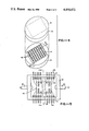
- FIG. 1 is a rear view of a semiconductor integrated circuit chip in accordance with one embodiment of the invention as seen through a transparent cover.
- the circuit is formed in a front surface of a semiconductor chip 10.
- the rear surface of the chip includes a recessed portion 12 and a plurality of parallel, microscopic heat conducting fins 14 rising from the recessed portion 12.
- "microscopic" means on the order of a fourth of a millimeter or less.
- the recessed portion 12 and fins 14 can be fabricated in the semiconductor chip 10 by conventional photoresist masking and chemical etching techniques or other conventional techniques.
- the transparent cover engages the surface of chip 10 and the tops of the fins 14 thereby defining a chamber for the flow of a coolant through input and output ports 16 and 18 in the transparent cover and in heat conducting contact with fins 14.
- the cover 20 is affixed to the major surface of chip 10 and to the tops of the heat conducting fins 14 thereby defining a chamber through which the coolant flows in heat conducting contact with the fins 14.
- Cover 20 can be made of the same semiconductor material as chip 10 or other compatible material such as glass.
- the cover may be anodically bonded to the chip or otherwise affixed thereto to define the liquid tight chamber.
- the fins 14 are positioned above the circuit shown generally at 22 in the front surface.
- FIG. 3 is a perspective view of an enlarged portion of the semiconductor chip of FIG. 1 with the width of each fin designated W w , the width of each channel designated W c , the length of each fin designated L, and the depth of each fin designated d.
- W c , W w can be determined for various liquids and fin materials provided that the heat conductivity of the liquid is much less than that of the fin material.
- ⁇ C volumetric heat capacity of coolant (J K -1 cm -3 )
- Nu is the Nusselt number which for long channels typically takes values from 3 to 9 depending on the ratio of channel depth d to channel width w c .
- the value of the aspect ratio d/(W c +W w ) should be preferably [k fin /(2k l Nu)] 1/2 because the thermal resistance of the assembly, i.e., the circuit temperature rise per unit of power dissipated, rapidly decreases as the aspect ratio increases to that value but only decreases slowly as the aspect ratio increases beyond that value.
- the channel width, W c for a channel not having a rectangular cross-section, is defined as twice the maximum value of the least distance from any point in the channel to a confining side wall.
- this preferably aspect ratio is approximately 4:1.
- the ratio of channel depth to width is about 8:1.
- the back surface of a silicon integrated circuit chip was anisotropically etched to give vertical walled fins of high aspect ratio.
- a Pyrex plate was bonded to the back of the substrate to confine the fluid to the channels.
- the fins were 300 microns high, 50 microns wide, with 50 micron channels between fins.
- a flow of room temperature water at approximately 9 milliliters per second at 31 psi pressure was above to remove 790 Watts over a square centimeter with a 71° C. maximum rise in device temperature.
- FIG. 4 is a perspective view of an alternative embodiment of the invention in which a first semiconductor chip 30 having an integrated circuit 31 defined in one major surface has a second heat conductive planar member 32 mounted on the opposite major surface for heat removal.
- the top surface of the planar member 32 has a recessed portion 34 defined therein with the plurality of rows of fins 36 being discontinuous.
- each row of fins comprises a plurality of posts.
- the heat conducting fins 36 and the member 32 are in intimate thermal contact with the integrated circuit chip 30 by means of suitable adhesive such as solder or epoxy. Coolant is provided to the chamber 34 through the input and output lines 37 and 38.
- FIGS. 5 and 6 are respectively front and end sectional views of another very compact embodiment of the invention.
- the semiconductor chip 40 includes the microscopic channels which run from one end to the other and a cover plate 43 is bonded to the back surface so as to enclose the channels.
- the assembly of chip 40 and cover plate 43 is mounted in a recessed portion 42 of a support shown generally as 44.
- the support 44 may be the conventional dual-in-line package (DIP) in which a plurality of conducting leads 46 extend from either side of the package and are interconnected with bonding pads 47 within the recessed portion 42. Wire connections are made from the circuit to the bonding pads 47.
- Lid 49 (not shown in FIG. 5) encloses the chip 40 in the support 44.
- a barrier, 48, of epoxy adhesive material serves to divide the recessed portion 42 into two chambers which are connected only by the channels in the chip 40.
- the adhesive material should cover the entire circuit surface.
- FIG. 7 is a front view of another embodiment of a semiconductor integrated circuit 60 which is mounted in a recessed portion 62 of a support shown generally at 64
- FIG. 8 is a sectional view taken along the line 8--8 of FIG. 7.
- the support 64 may again be the conventional dual-in-line package (DIP) in which a plurality of conductive leads 66 extend from either side of the package and are interconnected with bonding pads within the recessed portion 62.
- DIP dual-in-line package
- bonding pads of chip 60 are mounted on the pads 65 at the support 64 whereby the integrated circuit is interconnected with the leads 66.
- a suitable epoxy 68 is positioned about opposite sides of the chip 60 whereby the recessed portion 62 defines a coolant chamber when a cover 69 is mounted to the package 64 and abutts fins 61 of chip 60.
- a first tube 70 integral with the package provides a coolant to the chamber with the coolant laminarly flowing through the channels defined by the fins 61 of the semiconductor chip 60 to a second tube 72 for removal of the coolant.
- tubes 70 and 72 can be made of electrically conductive material and function as power busses to the integrated circuit chip 60.
- the invention has proved to offer a significant increase in heat removal capacity for integrated circuit arrays. While the invention has been described with reference to specific embodiments, the descriptions are illustrative of the invention and are not to be construed as limiting the invention.
- the flow of the coolant through the channels between the microscopic fins can be provided by gravity flow by mounting the semiconductor chips vertically.
- the channels can be formed by techniques other than chemical etching such as by laser scribing, reactive ion etching, electroplating, and ultrafine sawing. Phosphosilicate-glass reflow can be used in attaching the cover to the chip. Accordingly, various modifications and adaptations may occur to those skilled in the art without departing from the true spirit and scope of the invention as defined by the appended claims.
Abstract
Description
Claims (17)
[k.sub.fin /(2k.sub.l Nu)].sup.1/2
[k.sub.fin /(2k.sub.l Nu)].sup.1/2
[k.sub.fin /(2k.sub.l Nu)].sup.1/2
Priority Applications (2)
| Application Number | Priority Date | Filing Date | Title |
|---|---|---|---|
| US06/239,407 US4450472A (en) | 1981-03-02 | 1981-03-02 | Method and means for improved heat removal in compact semiconductor integrated circuits and similar devices utilizing coolant chambers and microscopic channels |
| US06/587,018 US4573067A (en) | 1981-03-02 | 1984-03-07 | Method and means for improved heat removal in compact semiconductor integrated circuits |
Applications Claiming Priority (1)
| Application Number | Priority Date | Filing Date | Title |
|---|---|---|---|
| US06/239,407 US4450472A (en) | 1981-03-02 | 1981-03-02 | Method and means for improved heat removal in compact semiconductor integrated circuits and similar devices utilizing coolant chambers and microscopic channels |
Related Child Applications (1)
| Application Number | Title | Priority Date | Filing Date |
|---|---|---|---|
| US06/587,018 Continuation US4573067A (en) | 1981-03-02 | 1984-03-07 | Method and means for improved heat removal in compact semiconductor integrated circuits |
Publications (1)
| Publication Number | Publication Date |
|---|---|
| US4450472A true US4450472A (en) | 1984-05-22 |
Family
ID=22902004
Family Applications (1)
| Application Number | Title | Priority Date | Filing Date |
|---|---|---|---|
| US06/239,407 Expired - Fee Related US4450472A (en) | 1981-03-02 | 1981-03-02 | Method and means for improved heat removal in compact semiconductor integrated circuits and similar devices utilizing coolant chambers and microscopic channels |
Country Status (1)
| Country | Link |
|---|---|
| US (1) | US4450472A (en) |
Cited By (122)
| Publication number | Priority date | Publication date | Assignee | Title |
|---|---|---|---|---|
| US4567505A (en) * | 1983-10-27 | 1986-01-28 | The Board Of Trustees Of The Leland Stanford Junior University | Heat sink and method of attaching heat sink to a semiconductor integrated circuit and the like |
| US4573067A (en) * | 1981-03-02 | 1986-02-25 | The Board Of Trustees Of The Leland Stanford Junior University | Method and means for improved heat removal in compact semiconductor integrated circuits |
| US4672421A (en) * | 1984-04-02 | 1987-06-09 | Motorola, Inc. | Semiconductor packaging and method |
| US4680673A (en) * | 1984-05-11 | 1987-07-14 | Societe Xeram | Encapsulated housing for dissipating heat produced by electrical circuits |
| US4868712A (en) * | 1987-02-04 | 1989-09-19 | Woodman John K | Three dimensional integrated circuit package |
| US4894709A (en) * | 1988-03-09 | 1990-01-16 | Massachusetts Institute Of Technology | Forced-convection, liquid-cooled, microchannel heat sinks |
| EP0353437A1 (en) * | 1988-07-14 | 1990-02-07 | Microelectronics and Computer Technology Corporation | An end fed liquid heat exchanger for an electronic component |
| GB2241112A (en) * | 1990-02-09 | 1991-08-21 | Asea Brown Boveri | Fluid cooled high-power semiconductor device |
| US5070040A (en) * | 1990-03-09 | 1991-12-03 | University Of Colorado Foundation, Inc. | Method and apparatus for semiconductor circuit chip cooling |
| US5083194A (en) * | 1990-01-16 | 1992-01-21 | Cray Research, Inc. | Air jet impingement on miniature pin-fin heat sinks for cooling electronic components |
| US5099311A (en) * | 1991-01-17 | 1992-03-24 | The United States Of America As Represented By The United States Department Of Energy | Microchannel heat sink assembly |
| US5125451A (en) * | 1991-04-02 | 1992-06-30 | Microunity Systems Engineering, Inc. | Heat exchanger for solid-state electronic devices |
| US5146314A (en) * | 1990-03-09 | 1992-09-08 | The University Of Colorado Foundation, Inc. | Apparatus for semiconductor circuit chip cooling using a diamond layer |
| US5166775A (en) * | 1990-01-16 | 1992-11-24 | Cray Research, Inc. | Air manifold for cooling electronic devices |
| US5179043A (en) * | 1989-07-14 | 1993-01-12 | The Texas A&M University System | Vapor deposited micro heat pipes |
| US5200248A (en) * | 1990-02-20 | 1993-04-06 | The Procter & Gamble Company | Open capillary channel structures, improved process for making capillary channel structures, and extrusion die for use therein |
| US5218515A (en) * | 1992-03-13 | 1993-06-08 | The United States Of America As Represented By The United States Department Of Energy | Microchannel cooling of face down bonded chips |
| US5230564A (en) * | 1992-03-20 | 1993-07-27 | Cray Research, Inc. | Temperature monitoring system for air-cooled electric components |
| US5241450A (en) * | 1992-03-13 | 1993-08-31 | The United States Of America As Represented By The United States Department Of Energy | Three dimensional, multi-chip module |
| US5242644A (en) * | 1990-02-20 | 1993-09-07 | The Procter & Gamble Company | Process for making capillary channel structures and extrusion die for use therein |
| US5249358A (en) * | 1992-04-28 | 1993-10-05 | Minnesota Mining And Manufacturing Company | Jet impingment plate and method of making |
| US5317805A (en) * | 1992-04-28 | 1994-06-07 | Minnesota Mining And Manufacturing Company | Method of making microchanneled heat exchangers utilizing sacrificial cores |
| US5321581A (en) * | 1992-03-20 | 1994-06-14 | Cray Research, Inc. | Air distribution system and manifold for cooling electronic components |
| US5427174A (en) * | 1993-04-30 | 1995-06-27 | Heat Transfer Devices, Inc. | Method and apparatus for a self contained heat exchanger |
| US5514906A (en) * | 1993-11-10 | 1996-05-07 | Fujitsu Limited | Apparatus for cooling semiconductor chips in multichip modules |
| WO1998003996A1 (en) * | 1996-07-22 | 1998-01-29 | Northrop Grumman Corporation | Microchannel cooling of high power semiconductor devices |
| US6039114A (en) * | 1996-01-04 | 2000-03-21 | Daimler - Benz Aktiengesellschaft | Cooling body having lugs |
| US20010050162A1 (en) * | 2000-06-08 | 2001-12-13 | Mikros Manufacturing, Inc. | Normal-flow heat exchanger |
| US6389582B1 (en) * | 1995-12-21 | 2002-05-14 | John Valainis | Thermal driven placement |
| US6400012B1 (en) | 1997-09-17 | 2002-06-04 | Advanced Energy Voorhees, Inc. | Heat sink for use in cooling an integrated circuit |
| US6422307B1 (en) * | 2001-07-18 | 2002-07-23 | Delphi Technologies, Inc. | Ultra high fin density heat sink for electronics cooling |
| US20030066634A1 (en) * | 2001-10-09 | 2003-04-10 | Mikros Manufacturing, Inc. | Heat exchanger |
| US20030085024A1 (en) * | 2001-09-28 | 2003-05-08 | Santiago Juan G | Control of electrolysis gases in electroosmotic pump systems |
| US6606251B1 (en) | 2002-02-07 | 2003-08-12 | Cooligy Inc. | Power conditioning module |
| US20030161104A1 (en) * | 2002-02-22 | 2003-08-28 | Hartzell Dennis E. | Finned-tube heat exchangers and cold plates, self-cooling electronic component systems using same, and methods for cooling electronic components using same |
| US6629425B2 (en) | 2000-07-24 | 2003-10-07 | Micron Technology, Inc. | MEMS heat pumps for integrated circuit heat dissipation |
| US20040080913A1 (en) * | 2002-02-12 | 2004-04-29 | Roy Zeighami | Method of cooling semiconductor die using microchannel thermosyphon |
| US20040089442A1 (en) * | 2001-09-28 | 2004-05-13 | The Board Of Trustees Of The Leland Stanford Junior University | Electroosmotic microchannel cooling system |
| WO2004042302A2 (en) * | 2002-11-01 | 2004-05-21 | Cooligy, Inc. | Channeled flat plate fin heat exchange system, device and method |
| US20040101421A1 (en) * | 2002-09-23 | 2004-05-27 | Kenny Thomas W. | Micro-fabricated electrokinetic pump with on-frit electrode |
| US20040104022A1 (en) * | 2002-11-01 | 2004-06-03 | Cooligy, Inc. | Method and apparatus for flexible fluid delivery for cooling desired hot spots in a heat producing device |
| US20040104012A1 (en) * | 2002-10-22 | 2004-06-03 | Cooligy, Inc. | Vapor escape microchannel heat exchanger |
| US20040112585A1 (en) * | 2002-11-01 | 2004-06-17 | Cooligy Inc. | Method and apparatus for achieving temperature uniformity and hot spot cooling in a heat producing device |
| US20040148959A1 (en) * | 2003-01-31 | 2004-08-05 | Cooligy, Inc. | Remedies to prevent cracking in a liquid system |
| US20040182551A1 (en) * | 2003-03-17 | 2004-09-23 | Cooligy, Inc. | Boiling temperature design in pumped microchannel cooling loops |
| US20040182548A1 (en) * | 2003-03-17 | 2004-09-23 | Cooligy, Inc. | Multi-level microchannel heat exchangers |
| US20040182560A1 (en) * | 2003-03-17 | 2004-09-23 | Cooligy Inc. | Apparatus and method of forming channels in a heat-exchanging device |
| US20040188065A1 (en) * | 2003-01-31 | 2004-09-30 | Cooligy, Inc. | Decoupled spring-loaded mounting apparatus and method of manufacturing thereof |
| US20040194492A1 (en) * | 2002-09-27 | 2004-10-07 | Isothermal Systems Research | Hotspot coldplate spray cooling system |
| US20040206477A1 (en) * | 2002-11-01 | 2004-10-21 | Cooligy, Inc. | Method and apparatus for efficient vertical fluid delivery for cooling a heat producing device |
| US20040244950A1 (en) * | 2003-01-31 | 2004-12-09 | Cooligy, Inc. | Optimized multiple heat pipe blocks for electronics cooling |
| US20050110145A1 (en) * | 2003-11-20 | 2005-05-26 | Kai-Erik Elers | Multilayer metallization |
| US20050128702A1 (en) * | 2003-12-12 | 2005-06-16 | Mongia Rajiv K. | Heat exchanger with cooling channels having varying geometry |
| US20050151244A1 (en) * | 2003-12-29 | 2005-07-14 | Intel Corporation | Integrated micro channels and manifold/plenum using separate silicon or low-cost polycrystalline silicon |
| US20050168079A1 (en) * | 2004-01-30 | 2005-08-04 | Isothermal Systems Research | Spindle-motor driven pump system |
| US20050185378A1 (en) * | 2004-02-24 | 2005-08-25 | Isothermal Systems Research | Etched open microchannel spray cooling |
| US20050183844A1 (en) * | 2004-02-24 | 2005-08-25 | Isothermal Systems Research | Hotspot spray cooling |
| US20050211417A1 (en) * | 2002-11-01 | 2005-09-29 | Cooligy,Inc. | Interwoven manifolds for pressure drop reduction in microchannel heat exchangers |
| US20050211427A1 (en) * | 2002-11-01 | 2005-09-29 | Cooligy, Inc. | Method and apparatus for flexible fluid delivery for cooling desired hot spots in a heat producing device |
| US20050217982A1 (en) * | 2004-02-18 | 2005-10-06 | Jung-Fa Chen | Power switching device to enable power switching between single phase power and three phase power |
| US20050268626A1 (en) * | 2004-06-04 | 2005-12-08 | Cooligy, Inc. | Method and apparatus for controlling freezing nucleation and propagation |
| US20050269061A1 (en) * | 2004-06-04 | 2005-12-08 | Cooligy, Inc. | Apparatus and method of efficient fluid delivery for cooling a heat producing device |
| US6986382B2 (en) | 2002-11-01 | 2006-01-17 | Cooligy Inc. | Interwoven manifolds for pressure drop reduction in microchannel heat exchangers |
| US20060042785A1 (en) * | 2004-08-27 | 2006-03-02 | Cooligy, Inc. | Pumped fluid cooling system and method |
| US20060171116A1 (en) * | 2003-07-08 | 2006-08-03 | Volker Lehmann | Integrated coolant circuit arrangement, operating method and production method |
| US20070000644A1 (en) * | 2005-06-29 | 2007-01-04 | Microvection, Inc. | Microchannel cooling device for small heat sources |
| US20070017662A1 (en) * | 2000-06-08 | 2007-01-25 | Mikros Manufacturing, Inc. | Normal-flow heat exchanger |
| EP1750303A2 (en) * | 2005-08-05 | 2007-02-07 | Delphi Technologies, Inc. | Method for the mitigation of hot spots in integrated circuits chip |
| US20070034356A1 (en) * | 2002-11-01 | 2007-02-15 | Cooligy, Inc. | Cooling systems incorporating heat exchangers and thermoelectric layers |
| US20070114010A1 (en) * | 2005-11-09 | 2007-05-24 | Girish Upadhya | Liquid cooling for backlit displays |
| EP1796165A2 (en) * | 2005-12-09 | 2007-06-13 | General Electric Company | Method of making an electronic device cooling system |
| US20070166878A1 (en) * | 2006-01-16 | 2007-07-19 | Chiu-Feng Li | Package structure and method for fabricating the same |
| US20070193642A1 (en) * | 2006-01-30 | 2007-08-23 | Douglas Werner | Tape-wrapped multilayer tubing and methods for making the same |
| US20070201210A1 (en) * | 2006-02-16 | 2007-08-30 | Norman Chow | Liquid cooling loops for server applications |
| US7265976B1 (en) | 2004-04-19 | 2007-09-04 | Isothermal Systems Research, Inc. | Microchannel thermal management system |
| US7277284B2 (en) | 2004-03-30 | 2007-10-02 | Purdue Research Foundation | Microchannel heat sink |
| US20070227698A1 (en) * | 2006-03-30 | 2007-10-04 | Conway Bruce R | Integrated fluid pump and radiator reservoir |
| US20070235167A1 (en) * | 2006-04-11 | 2007-10-11 | Cooligy, Inc. | Methodology of cooling multiple heat sources in a personal computer through the use of multiple fluid-based heat exchanging loops coupled via modular bus-type heat exchangers |
| US20080006396A1 (en) * | 2006-06-30 | 2008-01-10 | Girish Upadhya | Multi-stage staggered radiator for high performance liquid cooling applications |
| US20080041560A1 (en) * | 2002-04-02 | 2008-02-21 | Paradis Leo R | Diamond heat sink |
| US20080047694A1 (en) * | 2006-08-27 | 2008-02-28 | Delano Andrew D | Heat transfer apparatus and methods |
| US20080073062A1 (en) * | 2006-09-26 | 2008-03-27 | Onscreen Technologies, Inc. | Sealed self-contained fluidic cooling device |
| US20080087456A1 (en) * | 2006-10-13 | 2008-04-17 | Onscreen Technologies, Inc. | Circuit board assemblies with combined fluid-containing heatspreader-ground plane and methods therefor |
| US20080097143A1 (en) * | 2004-06-08 | 2008-04-24 | Eurica Califorrniaa | Side-vented microcradle for prenidial incubator |
| US20080115916A1 (en) * | 2006-11-16 | 2008-05-22 | Onscreen Technologies, Inc. | Cooling device for an electronic component |
| US20080190586A1 (en) * | 2007-02-08 | 2008-08-14 | Onscreen Technologies, Inc. | Carbon-based waterblock with attached heat exchanger for cooling of electronic devices |
| US20080210405A1 (en) * | 2002-11-01 | 2008-09-04 | Madhav Datta | Fabrication of high surface to volume ratio structures and their integration in microheat exchangers for liquid cooling systems |
| US20090046430A1 (en) * | 2007-08-07 | 2009-02-19 | Richard Grant Brewer | Method and apparatus for providing supplemental cooling to server racks |
| US20090225515A1 (en) * | 2008-03-10 | 2009-09-10 | James Hom | Thermal bus or junction for the removal of heat from electronic components |
| US20090229794A1 (en) * | 2007-12-28 | 2009-09-17 | Schon Steven G | Heat pipes incorporating microchannel heat exchangers |
| US20090242048A1 (en) * | 2008-03-26 | 2009-10-01 | 3M Innovative Properties Company | Structured polydiorganosiloxane polyamide containing devices and methods |
| US7616444B2 (en) | 2004-06-04 | 2009-11-10 | Cooligy Inc. | Gimballed attachment for multiple heat exchangers |
| US20100184248A1 (en) * | 2008-02-05 | 2010-07-22 | Twin Creeks Technologies, Inc. | Creation and Translation of Low-Relieff Texture for a Photovoltaic Cell |
| US20110073292A1 (en) * | 2009-09-30 | 2011-03-31 | Madhav Datta | Fabrication of high surface area, high aspect ratio mini-channels and their application in liquid cooling systems |
| US20110100603A1 (en) * | 2005-06-29 | 2011-05-05 | Science Research Laboratory, Inc. | Microchannel cooling device for small heat sources |
| US20110226445A1 (en) * | 2010-03-22 | 2011-09-22 | Brand Joseph H | Heat exchanger |
| US20110237013A1 (en) * | 2010-03-23 | 2011-09-29 | Twin Creeks Technologies, Inc. | Creation of Low-Relief Texture for a Photovoltaic Cell |
| WO2012005706A1 (en) | 2010-07-07 | 2012-01-12 | Haluk Kulah | Cmos compatible microchannel heat sink for electronic cooling and its fabrication |
| US8157001B2 (en) | 2006-03-30 | 2012-04-17 | Cooligy Inc. | Integrated liquid to air conduction module |
| US20120111553A1 (en) * | 2009-05-18 | 2012-05-10 | Vadim Tsoi | Heat spreading device and method therefore |
| US20120135602A1 (en) * | 2010-07-26 | 2012-05-31 | Hamamatsu Photonics K.K. | Method for manufacturing semiconductor device |
| US8254422B2 (en) | 2008-08-05 | 2012-08-28 | Cooligy Inc. | Microheat exchanger for laser diode cooling |
| DE112010004672T5 (en) | 2009-12-02 | 2013-04-18 | National University Of Singapore | An improved heat sink |
| US20130148305A1 (en) * | 2011-12-08 | 2013-06-13 | Oracle International Corporation | Design of a heat dissipation structure for an integrated circuit (ic) chip |
| US9012278B2 (en) | 2013-10-03 | 2015-04-21 | Asm Ip Holding B.V. | Method of making a wire-based semiconductor device |
| US9041193B2 (en) | 2013-09-17 | 2015-05-26 | Hamilton Sundstrand Corporation | Semiconductor substrate including a cooling channel and method of forming a semiconductor substrate including a cooling channel |
| JP5757086B2 (en) * | 2008-10-29 | 2015-07-29 | 日本電気株式会社 | COOLING STRUCTURE, ELECTRONIC DEVICE, AND COOLING METHOD |
| US9297571B1 (en) | 2008-03-10 | 2016-03-29 | Liebert Corporation | Device and methodology for the removal of heat from an equipment rack by means of heat exchangers mounted to a door |
| US9603284B2 (en) | 2007-08-09 | 2017-03-21 | Coolit Systems, Inc. | Fluid heat exchanger configured to provide a split flow |
| EP2599112A4 (en) * | 2010-07-30 | 2017-07-26 | MonolithIC 3D S.A. | Semiconductor device and structure |
| US20170245394A1 (en) * | 2016-02-18 | 2017-08-24 | Ironside Engineering Inc. | High Efficiency Heat Dissipation Methods And Systems For Electronic Circuits And Systems |
| US10274266B2 (en) | 2007-08-09 | 2019-04-30 | CoolIT Systems, Inc | Fluid heat exchange sytems |
| US10365667B2 (en) | 2011-08-11 | 2019-07-30 | Coolit Systems, Inc. | Flow-path controllers and related systems |
| US10364809B2 (en) | 2013-03-15 | 2019-07-30 | Coolit Systems, Inc. | Sensors, multiplexed communication techniques, and related systems |
| US10415597B2 (en) | 2014-10-27 | 2019-09-17 | Coolit Systems, Inc. | Fluid heat exchange systems |
| WO2021121560A1 (en) | 2019-12-17 | 2021-06-24 | Ecole Polytechnique Federale De Lausanne (Epfl) | Integrated electronic device with embedded microchannels and a method for producing thereof |
| US11081424B2 (en) | 2019-06-18 | 2021-08-03 | International Business Machines Corporation | Micro-fluidic channels having various critical dimensions |
| US11395443B2 (en) | 2020-05-11 | 2022-07-19 | Coolit Systems, Inc. | Liquid pumping units, and related systems and methods |
| US11473860B2 (en) | 2019-04-25 | 2022-10-18 | Coolit Systems, Inc. | Cooling module with leak detector and related systems |
| US11662037B2 (en) | 2019-01-18 | 2023-05-30 | Coolit Systems, Inc. | Fluid flow control valve for fluid flow systems, and methods |
| US11725886B2 (en) | 2021-05-20 | 2023-08-15 | Coolit Systems, Inc. | Modular fluid heat exchange systems |
| US11962129B2 (en) | 2021-04-09 | 2024-04-16 | Lawrence Livermore National Security, Llc | Systems and methods for laser diode array having integrated microchannel cooling |
-
1981
- 1981-03-02 US US06/239,407 patent/US4450472A/en not_active Expired - Fee Related
Non-Patent Citations (10)
| Title |
|---|
| "Grooved Substrate Boosts IC Cooling", Electronics, Aug. 25, 1982, p. 46. |
| "Heat Exchange Element for Semiconductor Device Cooling" H. D. Edmonds and G. Markovits IBM Technical Disclosure Bulletin, vol. 23, No. 3, Aug. 1980, p. 1057. |
| "Heat Transfer from Silicon Chips and Wafers" R. W. Noth IBM Technical Disclosure Bulletin, vol. 17, No. 12, May 1975, p. 3544. |
| "Integrally Grooved Semiconductor Chip and Heat Sink" A. H. Johnson IBM Technical Disclosure Bulletin, vol. 14, No. 5, Oct.1971, p. 1425. |
| "Liquid Cooling of Integrated Circuit Chips" W. Anacker IBM Technical Disclosure Bulletin, vol. 20, No. 9, Feb. 1978, pp. 3742-3743. |
| Grooved Substrate Boosts IC Cooling , Electronics, Aug. 25, 1982, p. 46. * |
| Heat Exchange Element for Semiconductor Device Cooling H. D. Edmonds and G. Markovits IBM Technical Disclosure Bulletin, vol. 23, No. 3, Aug. 1980, p. 1057. * |
| Heat Transfer from Silicon Chips and Wafers R. W. Noth IBM Technical Disclosure Bulletin, vol. 17, No. 12, May 1975, p. 3544. * |
| Integrally Grooved Semiconductor Chip and Heat Sink A. H. Johnson IBM Technical Disclosure Bulletin, vol. 14, No. 5, Oct.1971, p. 1425. * |
| Liquid Cooling of Integrated Circuit Chips W. Anacker IBM Technical Disclosure Bulletin, vol. 20, No. 9, Feb. 1978, pp. 3742 3743. * |
Cited By (222)
| Publication number | Priority date | Publication date | Assignee | Title |
|---|---|---|---|---|
| US4573067A (en) * | 1981-03-02 | 1986-02-25 | The Board Of Trustees Of The Leland Stanford Junior University | Method and means for improved heat removal in compact semiconductor integrated circuits |
| US4567505A (en) * | 1983-10-27 | 1986-01-28 | The Board Of Trustees Of The Leland Stanford Junior University | Heat sink and method of attaching heat sink to a semiconductor integrated circuit and the like |
| US4672421A (en) * | 1984-04-02 | 1987-06-09 | Motorola, Inc. | Semiconductor packaging and method |
| US4680673A (en) * | 1984-05-11 | 1987-07-14 | Societe Xeram | Encapsulated housing for dissipating heat produced by electrical circuits |
| US4868712A (en) * | 1987-02-04 | 1989-09-19 | Woodman John K | Three dimensional integrated circuit package |
| US4894709A (en) * | 1988-03-09 | 1990-01-16 | Massachusetts Institute Of Technology | Forced-convection, liquid-cooled, microchannel heat sinks |
| EP0353437A1 (en) * | 1988-07-14 | 1990-02-07 | Microelectronics and Computer Technology Corporation | An end fed liquid heat exchanger for an electronic component |
| US5179043A (en) * | 1989-07-14 | 1993-01-12 | The Texas A&M University System | Vapor deposited micro heat pipes |
| US5166775A (en) * | 1990-01-16 | 1992-11-24 | Cray Research, Inc. | Air manifold for cooling electronic devices |
| US5083194A (en) * | 1990-01-16 | 1992-01-21 | Cray Research, Inc. | Air jet impingement on miniature pin-fin heat sinks for cooling electronic components |
| GB2241112A (en) * | 1990-02-09 | 1991-08-21 | Asea Brown Boveri | Fluid cooled high-power semiconductor device |
| US5242644A (en) * | 1990-02-20 | 1993-09-07 | The Procter & Gamble Company | Process for making capillary channel structures and extrusion die for use therein |
| US5200248A (en) * | 1990-02-20 | 1993-04-06 | The Procter & Gamble Company | Open capillary channel structures, improved process for making capillary channel structures, and extrusion die for use therein |
| US5146314A (en) * | 1990-03-09 | 1992-09-08 | The University Of Colorado Foundation, Inc. | Apparatus for semiconductor circuit chip cooling using a diamond layer |
| US5070040A (en) * | 1990-03-09 | 1991-12-03 | University Of Colorado Foundation, Inc. | Method and apparatus for semiconductor circuit chip cooling |
| US5099311A (en) * | 1991-01-17 | 1992-03-24 | The United States Of America As Represented By The United States Department Of Energy | Microchannel heat sink assembly |
| US5125451A (en) * | 1991-04-02 | 1992-06-30 | Microunity Systems Engineering, Inc. | Heat exchanger for solid-state electronic devices |
| US5274920A (en) * | 1991-04-02 | 1994-01-04 | Microunity Systems Engineering | Method of fabricating a heat exchanger for solid-state electronic devices |
| US5218515A (en) * | 1992-03-13 | 1993-06-08 | The United States Of America As Represented By The United States Department Of Energy | Microchannel cooling of face down bonded chips |
| US5241450A (en) * | 1992-03-13 | 1993-08-31 | The United States Of America As Represented By The United States Department Of Energy | Three dimensional, multi-chip module |
| US5230564A (en) * | 1992-03-20 | 1993-07-27 | Cray Research, Inc. | Temperature monitoring system for air-cooled electric components |
| US5281026A (en) * | 1992-03-20 | 1994-01-25 | Cray Research, Inc. | Printed circuit board with cooling monitoring system |
| US5321581A (en) * | 1992-03-20 | 1994-06-14 | Cray Research, Inc. | Air distribution system and manifold for cooling electronic components |
| US5317805A (en) * | 1992-04-28 | 1994-06-07 | Minnesota Mining And Manufacturing Company | Method of making microchanneled heat exchangers utilizing sacrificial cores |
| US5249358A (en) * | 1992-04-28 | 1993-10-05 | Minnesota Mining And Manufacturing Company | Jet impingment plate and method of making |
| US5427174A (en) * | 1993-04-30 | 1995-06-27 | Heat Transfer Devices, Inc. | Method and apparatus for a self contained heat exchanger |
| US5514906A (en) * | 1993-11-10 | 1996-05-07 | Fujitsu Limited | Apparatus for cooling semiconductor chips in multichip modules |
| US6389582B1 (en) * | 1995-12-21 | 2002-05-14 | John Valainis | Thermal driven placement |
| US6039114A (en) * | 1996-01-04 | 2000-03-21 | Daimler - Benz Aktiengesellschaft | Cooling body having lugs |
| US5801442A (en) * | 1996-07-22 | 1998-09-01 | Northrop Grumman Corporation | Microchannel cooling of high power semiconductor devices |
| US5998240A (en) * | 1996-07-22 | 1999-12-07 | Northrop Grumman Corporation | Method of extracting heat from a semiconductor body and forming microchannels therein |
| WO1998003996A1 (en) * | 1996-07-22 | 1998-01-29 | Northrop Grumman Corporation | Microchannel cooling of high power semiconductor devices |
| US6400012B1 (en) | 1997-09-17 | 2002-06-04 | Advanced Energy Voorhees, Inc. | Heat sink for use in cooling an integrated circuit |
| US20010050162A1 (en) * | 2000-06-08 | 2001-12-13 | Mikros Manufacturing, Inc. | Normal-flow heat exchanger |
| US20070017662A1 (en) * | 2000-06-08 | 2007-01-25 | Mikros Manufacturing, Inc. | Normal-flow heat exchanger |
| US7302998B2 (en) | 2000-06-08 | 2007-12-04 | Mikros Manufacturing, Inc. | Normal-flow heat exchanger |
| US20080066894A1 (en) * | 2000-06-08 | 2008-03-20 | Mikros Manufacturing, Inc. | Normal-flow heat exchanger |
| US6935411B2 (en) | 2000-06-08 | 2005-08-30 | Mikros Manufacturing, Inc. | Normal-flow heat exchanger |
| US7836943B2 (en) | 2000-06-08 | 2010-11-23 | Mikros Manufacturing, Inc. | Normal-flow heat exchanger |
| US7084004B2 (en) | 2000-07-24 | 2006-08-01 | Micron Technology, Inc. | MEMS heat pumps for integrated circuit heat dissipation |
| US7107777B2 (en) | 2000-07-24 | 2006-09-19 | Micro Technology, Inc. | MEMS heat pumps for integrated circuit heat dissipation |
| US20060236710A1 (en) * | 2000-07-24 | 2006-10-26 | Venkateshwaran Vaiyapuri | MEMS heat pumps for integrated circuit heat dissipation |
| US20040031594A1 (en) * | 2000-07-24 | 2004-02-19 | Venkateshwaran Vaiyapuri | MEMS heat pumps for integrated circuit heat dissipation |
| US20040031281A1 (en) * | 2000-07-24 | 2004-02-19 | Venkateshwaran Vaiyapuri | MEMS heat pumps for integrated circuit heat dissipation |
| US6629425B2 (en) | 2000-07-24 | 2003-10-07 | Micron Technology, Inc. | MEMS heat pumps for integrated circuit heat dissipation |
| US20060236711A1 (en) * | 2000-07-24 | 2006-10-26 | Venkateshwaran Vaiyapuri | MEMS heat pumps for integrated circuit heat dissipation |
| US20060189022A1 (en) * | 2000-07-24 | 2006-08-24 | Venkateshwaran Vaiyapuri | MEMS heat pumps for integrated circuit heat dissipation |
| US6422307B1 (en) * | 2001-07-18 | 2002-07-23 | Delphi Technologies, Inc. | Ultra high fin density heat sink for electronics cooling |
| US6942018B2 (en) | 2001-09-28 | 2005-09-13 | The Board Of Trustees Of The Leland Stanford Junior University | Electroosmotic microchannel cooling system |
| US20030085024A1 (en) * | 2001-09-28 | 2003-05-08 | Santiago Juan G | Control of electrolysis gases in electroosmotic pump systems |
| US7334630B2 (en) | 2001-09-28 | 2008-02-26 | The Board Of Trustees Of The Leland Stanford Junior University | Closed-loop microchannel cooling system |
| US20050205241A1 (en) * | 2001-09-28 | 2005-09-22 | The Board Of Trustees Of The Leland Stanford Junior University | Closed-loop microchannel cooling system |
| US20040089442A1 (en) * | 2001-09-28 | 2004-05-13 | The Board Of Trustees Of The Leland Stanford Junior University | Electroosmotic microchannel cooling system |
| US7131486B2 (en) | 2001-09-28 | 2006-11-07 | The Board Of Trustees Of The Leland Stanford Junior Universty | Electroosmotic microchannel cooling system |
| US6991024B2 (en) | 2001-09-28 | 2006-01-31 | The Board Of Trustees Of The Leland Stanford Junior University | Electroosmotic microchannel cooling system |
| US7134486B2 (en) | 2001-09-28 | 2006-11-14 | The Board Of Trustees Of The Leeland Stanford Junior University | Control of electrolysis gases in electroosmotic pump systems |
| US20030066634A1 (en) * | 2001-10-09 | 2003-04-10 | Mikros Manufacturing, Inc. | Heat exchanger |
| US7278474B2 (en) | 2001-10-09 | 2007-10-09 | Mikros Manufacturing, Inc. | Heat exchanger |
| US20030173942A1 (en) * | 2002-02-07 | 2003-09-18 | Cooligy, Inc. | Apparatus for conditioning power and managing thermal energy in an electronic device |
| US7050308B2 (en) | 2002-02-07 | 2006-05-23 | Cooligy, Inc. | Power conditioning module |
| US6606251B1 (en) | 2002-02-07 | 2003-08-12 | Cooligy Inc. | Power conditioning module |
| US20040240245A1 (en) * | 2002-02-07 | 2004-12-02 | Cooligy, Inc. | Power conditioning module |
| US6678168B2 (en) | 2002-02-07 | 2004-01-13 | Cooligy, Inc. | System including power conditioning modules |
| US20040252535A1 (en) * | 2002-02-07 | 2004-12-16 | Cooligy, Inc. | Apparatus for conditioning power and managing thermal energy in an electronic device |
| US20050094374A1 (en) * | 2002-02-07 | 2005-05-05 | Cooligy, Inc. | Power conditioning module |
| US7061104B2 (en) | 2002-02-07 | 2006-06-13 | Cooligy, Inc. | Apparatus for conditioning power and managing thermal energy in an electronic device |
| US20040080913A1 (en) * | 2002-02-12 | 2004-04-29 | Roy Zeighami | Method of cooling semiconductor die using microchannel thermosyphon |
| US7002801B2 (en) * | 2002-02-12 | 2006-02-21 | Hewlett-Packard Development Company, L.P. | Method of cooling semiconductor die using microchannel thermosyphon |
| US20030161104A1 (en) * | 2002-02-22 | 2003-08-28 | Hartzell Dennis E. | Finned-tube heat exchangers and cold plates, self-cooling electronic component systems using same, and methods for cooling electronic components using same |
| US6819561B2 (en) | 2002-02-22 | 2004-11-16 | Satcon Technology Corporation | Finned-tube heat exchangers and cold plates, self-cooling electronic component systems using same, and methods for cooling electronic components using same |
| US20080041560A1 (en) * | 2002-04-02 | 2008-02-21 | Paradis Leo R | Diamond heat sink |
| US20040101421A1 (en) * | 2002-09-23 | 2004-05-27 | Kenny Thomas W. | Micro-fabricated electrokinetic pump with on-frit electrode |
| US7086839B2 (en) | 2002-09-23 | 2006-08-08 | Cooligy, Inc. | Micro-fabricated electrokinetic pump with on-frit electrode |
| US20040194492A1 (en) * | 2002-09-27 | 2004-10-07 | Isothermal Systems Research | Hotspot coldplate spray cooling system |
| US7159414B2 (en) | 2002-09-27 | 2007-01-09 | Isothermal Systems Research Inc. | Hotspot coldplate spray cooling system |
| US20040104012A1 (en) * | 2002-10-22 | 2004-06-03 | Cooligy, Inc. | Vapor escape microchannel heat exchanger |
| US6994151B2 (en) | 2002-10-22 | 2006-02-07 | Cooligy, Inc. | Vapor escape microchannel heat exchanger |
| US7806168B2 (en) | 2002-11-01 | 2010-10-05 | Cooligy Inc | Optimal spreader system, device and method for fluid cooled micro-scaled heat exchange |
| US20040112585A1 (en) * | 2002-11-01 | 2004-06-17 | Cooligy Inc. | Method and apparatus for achieving temperature uniformity and hot spot cooling in a heat producing device |
| US20050211417A1 (en) * | 2002-11-01 | 2005-09-29 | Cooligy,Inc. | Interwoven manifolds for pressure drop reduction in microchannel heat exchangers |
| US20050211427A1 (en) * | 2002-11-01 | 2005-09-29 | Cooligy, Inc. | Method and apparatus for flexible fluid delivery for cooling desired hot spots in a heat producing device |
| US20070034356A1 (en) * | 2002-11-01 | 2007-02-15 | Cooligy, Inc. | Cooling systems incorporating heat exchangers and thermoelectric layers |
| US8464781B2 (en) | 2002-11-01 | 2013-06-18 | Cooligy Inc. | Cooling systems incorporating heat exchangers and thermoelectric layers |
| US20040188064A1 (en) * | 2002-11-01 | 2004-09-30 | Cooligy Inc. | Channeled flat plate fin heat exchange system, device and method |
| US7836597B2 (en) | 2002-11-01 | 2010-11-23 | Cooligy Inc. | Method of fabricating high surface to volume ratio structures and their integration in microheat exchangers for liquid cooling system |
| WO2004042302A2 (en) * | 2002-11-01 | 2004-05-21 | Cooligy, Inc. | Channeled flat plate fin heat exchange system, device and method |
| US20040104022A1 (en) * | 2002-11-01 | 2004-06-03 | Cooligy, Inc. | Method and apparatus for flexible fluid delivery for cooling desired hot spots in a heat producing device |
| US6986382B2 (en) | 2002-11-01 | 2006-01-17 | Cooligy Inc. | Interwoven manifolds for pressure drop reduction in microchannel heat exchangers |
| US6988535B2 (en) * | 2002-11-01 | 2006-01-24 | Cooligy, Inc. | Channeled flat plate fin heat exchange system, device and method |
| US6988534B2 (en) | 2002-11-01 | 2006-01-24 | Cooligy, Inc. | Method and apparatus for flexible fluid delivery for cooling desired hot spots in a heat producing device |
| US20040188066A1 (en) * | 2002-11-01 | 2004-09-30 | Cooligy, Inc. | Optimal spreader system, device and method for fluid cooled micro-scaled heat exchange |
| US20040206477A1 (en) * | 2002-11-01 | 2004-10-21 | Cooligy, Inc. | Method and apparatus for efficient vertical fluid delivery for cooling a heat producing device |
| US20080210405A1 (en) * | 2002-11-01 | 2008-09-04 | Madhav Datta | Fabrication of high surface to volume ratio structures and their integration in microheat exchangers for liquid cooling systems |
| US7000684B2 (en) | 2002-11-01 | 2006-02-21 | Cooligy, Inc. | Method and apparatus for efficient vertical fluid delivery for cooling a heat producing device |
| WO2004042302A3 (en) * | 2002-11-01 | 2005-05-12 | Cooligy Inc | Channeled flat plate fin heat exchange system, device and method |
| US7104312B2 (en) | 2002-11-01 | 2006-09-12 | Cooligy, Inc. | Method and apparatus for achieving temperature uniformity and hot spot cooling in a heat producing device |
| US7344363B2 (en) | 2003-01-31 | 2008-03-18 | Cooligy Inc. | Remedies to prevent cracking in a liquid system |
| US20050210913A1 (en) * | 2003-01-31 | 2005-09-29 | Mark Munch | Remedies to prevent cracking in a liquid system |
| US7201214B2 (en) | 2003-01-31 | 2007-04-10 | Cooligy, Inc. | Remedies to prevent cracking in a liquid system |
| US7044196B2 (en) | 2003-01-31 | 2006-05-16 | Cooligy,Inc | Decoupled spring-loaded mounting apparatus and method of manufacturing thereof |
| US7201012B2 (en) | 2003-01-31 | 2007-04-10 | Cooligy, Inc. | Remedies to prevent cracking in a liquid system |
| US20050183444A1 (en) * | 2003-01-31 | 2005-08-25 | Mark Munch | Remedies to prevent cracking in a liquid system |
| US20040148959A1 (en) * | 2003-01-31 | 2004-08-05 | Cooligy, Inc. | Remedies to prevent cracking in a liquid system |
| US20050183845A1 (en) * | 2003-01-31 | 2005-08-25 | Mark Munch | Remedies to prevent cracking in a liquid system |
| US7278549B2 (en) | 2003-01-31 | 2007-10-09 | Cooligy Inc. | Remedies to prevent cracking in a liquid system |
| US7090001B2 (en) | 2003-01-31 | 2006-08-15 | Cooligy, Inc. | Optimized multiple heat pipe blocks for electronics cooling |
| US20040188065A1 (en) * | 2003-01-31 | 2004-09-30 | Cooligy, Inc. | Decoupled spring-loaded mounting apparatus and method of manufacturing thereof |
| US7402029B2 (en) | 2003-01-31 | 2008-07-22 | Cooligy Inc. | Remedies to prevent cracking in a liquid system |
| US20050183445A1 (en) * | 2003-01-31 | 2005-08-25 | Mark Munch | Remedies to prevent cracking in a liquid system |
| US20050183443A1 (en) * | 2003-01-31 | 2005-08-25 | Mark Munch | Remedies to prevent cracking in a liquid system |
| US20040244950A1 (en) * | 2003-01-31 | 2004-12-09 | Cooligy, Inc. | Optimized multiple heat pipe blocks for electronics cooling |
| US20040182560A1 (en) * | 2003-03-17 | 2004-09-23 | Cooligy Inc. | Apparatus and method of forming channels in a heat-exchanging device |
| US20040182548A1 (en) * | 2003-03-17 | 2004-09-23 | Cooligy, Inc. | Multi-level microchannel heat exchangers |
| US7156159B2 (en) | 2003-03-17 | 2007-01-02 | Cooligy, Inc. | Multi-level microchannel heat exchangers |
| US20040182551A1 (en) * | 2003-03-17 | 2004-09-23 | Cooligy, Inc. | Boiling temperature design in pumped microchannel cooling loops |
| US7017654B2 (en) | 2003-03-17 | 2006-03-28 | Cooligy, Inc. | Apparatus and method of forming channels in a heat-exchanging device |
| US7872349B2 (en) * | 2003-07-08 | 2011-01-18 | Infineon Technologies Ag | Integrated coolant circuit arrangement, operating method and production method |
| US20060171116A1 (en) * | 2003-07-08 | 2006-08-03 | Volker Lehmann | Integrated coolant circuit arrangement, operating method and production method |
| US20050110145A1 (en) * | 2003-11-20 | 2005-05-26 | Kai-Erik Elers | Multilayer metallization |
| US7018917B2 (en) | 2003-11-20 | 2006-03-28 | Asm International N.V. | Multilayer metallization |
| US20050128702A1 (en) * | 2003-12-12 | 2005-06-16 | Mongia Rajiv K. | Heat exchanger with cooling channels having varying geometry |
| US7203064B2 (en) * | 2003-12-12 | 2007-04-10 | Intel Corporation | Heat exchanger with cooling channels having varying geometry |
| US7435623B2 (en) | 2003-12-29 | 2008-10-14 | Intel Corporation | Integrated micro channels and manifold/plenum using separate silicon or low-cost polycrystalline silicon |
| US6992382B2 (en) | 2003-12-29 | 2006-01-31 | Intel Corporation | Integrated micro channels and manifold/plenum using separate silicon or low-cost polycrystalline silicon |
| US20060071326A1 (en) * | 2003-12-29 | 2006-04-06 | Intel Corporation | Integrated micro channels and manifold/plenum using separate silicon or low-cost polycrystalline silicon |
| US20050151244A1 (en) * | 2003-12-29 | 2005-07-14 | Intel Corporation | Integrated micro channels and manifold/plenum using separate silicon or low-cost polycrystalline silicon |
| US7131825B2 (en) | 2004-01-30 | 2006-11-07 | Isothermal Systems Research, Inc. | Spindle-motor driven pump system |
| US20050168079A1 (en) * | 2004-01-30 | 2005-08-04 | Isothermal Systems Research | Spindle-motor driven pump system |
| US6977350B2 (en) * | 2004-02-18 | 2005-12-20 | Acbel Polytech Inc. | Power switching device to enable power switching between single phase power and three phase power |
| US20050217982A1 (en) * | 2004-02-18 | 2005-10-06 | Jung-Fa Chen | Power switching device to enable power switching between single phase power and three phase power |
| US20050183844A1 (en) * | 2004-02-24 | 2005-08-25 | Isothermal Systems Research | Hotspot spray cooling |
| US6952346B2 (en) | 2004-02-24 | 2005-10-04 | Isothermal Systems Research, Inc | Etched open microchannel spray cooling |
| US20050185378A1 (en) * | 2004-02-24 | 2005-08-25 | Isothermal Systems Research | Etched open microchannel spray cooling |
| US7277284B2 (en) | 2004-03-30 | 2007-10-02 | Purdue Research Foundation | Microchannel heat sink |
| US7265976B1 (en) | 2004-04-19 | 2007-09-04 | Isothermal Systems Research, Inc. | Microchannel thermal management system |
| US20050269061A1 (en) * | 2004-06-04 | 2005-12-08 | Cooligy, Inc. | Apparatus and method of efficient fluid delivery for cooling a heat producing device |
| US7293423B2 (en) | 2004-06-04 | 2007-11-13 | Cooligy Inc. | Method and apparatus for controlling freezing nucleation and propagation |
| US7188662B2 (en) | 2004-06-04 | 2007-03-13 | Cooligy, Inc. | Apparatus and method of efficient fluid delivery for cooling a heat producing device |
| US7616444B2 (en) | 2004-06-04 | 2009-11-10 | Cooligy Inc. | Gimballed attachment for multiple heat exchangers |
| US20050268626A1 (en) * | 2004-06-04 | 2005-12-08 | Cooligy, Inc. | Method and apparatus for controlling freezing nucleation and propagation |
| US20080097143A1 (en) * | 2004-06-08 | 2008-04-24 | Eurica Califorrniaa | Side-vented microcradle for prenidial incubator |
| US8292798B2 (en) | 2004-06-08 | 2012-10-23 | Eurica Califorrniaa | Incubator for babies before implantation |
| US20060042785A1 (en) * | 2004-08-27 | 2006-03-02 | Cooligy, Inc. | Pumped fluid cooling system and method |
| US7836940B2 (en) | 2005-06-29 | 2010-11-23 | Microvection, Inc. | Microchannel cooling device for small heat sources |
| US20110100603A1 (en) * | 2005-06-29 | 2011-05-05 | Science Research Laboratory, Inc. | Microchannel cooling device for small heat sources |
| US20070000644A1 (en) * | 2005-06-29 | 2007-01-04 | Microvection, Inc. | Microchannel cooling device for small heat sources |
| EP1750303A3 (en) * | 2005-08-05 | 2010-03-10 | Delphi Technologies, Inc. | Method for the mitigation of hot spots in integrated circuits chip |
| EP1750303A2 (en) * | 2005-08-05 | 2007-02-07 | Delphi Technologies, Inc. | Method for the mitigation of hot spots in integrated circuits chip |
| US20070114010A1 (en) * | 2005-11-09 | 2007-05-24 | Girish Upadhya | Liquid cooling for backlit displays |
| US20070131659A1 (en) * | 2005-12-09 | 2007-06-14 | Durocher Kevin M | Method of making an electronic device cooling system |
| EP1796165A2 (en) * | 2005-12-09 | 2007-06-13 | General Electric Company | Method of making an electronic device cooling system |
| EP1796165A3 (en) * | 2005-12-09 | 2010-03-24 | General Electric Company | Method of making an electronic device cooling system |
| US20070166878A1 (en) * | 2006-01-16 | 2007-07-19 | Chiu-Feng Li | Package structure and method for fabricating the same |
| US7913719B2 (en) * | 2006-01-30 | 2011-03-29 | Cooligy Inc. | Tape-wrapped multilayer tubing and methods for making the same |
| US20070193642A1 (en) * | 2006-01-30 | 2007-08-23 | Douglas Werner | Tape-wrapped multilayer tubing and methods for making the same |
| US7599184B2 (en) | 2006-02-16 | 2009-10-06 | Cooligy Inc. | Liquid cooling loops for server applications |
| US20070201210A1 (en) * | 2006-02-16 | 2007-08-30 | Norman Chow | Liquid cooling loops for server applications |
| US7539020B2 (en) | 2006-02-16 | 2009-05-26 | Cooligy Inc. | Liquid cooling loops for server applications |
| US8157001B2 (en) | 2006-03-30 | 2012-04-17 | Cooligy Inc. | Integrated liquid to air conduction module |
| US20070227698A1 (en) * | 2006-03-30 | 2007-10-04 | Conway Bruce R | Integrated fluid pump and radiator reservoir |
| US7715194B2 (en) | 2006-04-11 | 2010-05-11 | Cooligy Inc. | Methodology of cooling multiple heat sources in a personal computer through the use of multiple fluid-based heat exchanging loops coupled via modular bus-type heat exchangers |
| US20070235167A1 (en) * | 2006-04-11 | 2007-10-11 | Cooligy, Inc. | Methodology of cooling multiple heat sources in a personal computer through the use of multiple fluid-based heat exchanging loops coupled via modular bus-type heat exchangers |
| US20080006396A1 (en) * | 2006-06-30 | 2008-01-10 | Girish Upadhya | Multi-stage staggered radiator for high performance liquid cooling applications |
| US20080047694A1 (en) * | 2006-08-27 | 2008-02-28 | Delano Andrew D | Heat transfer apparatus and methods |
| US8561673B2 (en) | 2006-09-26 | 2013-10-22 | Olantra Fund X L.L.C. | Sealed self-contained fluidic cooling device |
| US20080073062A1 (en) * | 2006-09-26 | 2008-03-27 | Onscreen Technologies, Inc. | Sealed self-contained fluidic cooling device |
| US20080087456A1 (en) * | 2006-10-13 | 2008-04-17 | Onscreen Technologies, Inc. | Circuit board assemblies with combined fluid-containing heatspreader-ground plane and methods therefor |
| US8037927B2 (en) | 2006-11-16 | 2011-10-18 | CUI Global, Inc. | Cooling device for an electronic component |
| US20080115916A1 (en) * | 2006-11-16 | 2008-05-22 | Onscreen Technologies, Inc. | Cooling device for an electronic component |
| US8528628B2 (en) | 2007-02-08 | 2013-09-10 | Olantra Fund X L.L.C. | Carbon-based apparatus for cooling of electronic devices |
| US20080190586A1 (en) * | 2007-02-08 | 2008-08-14 | Onscreen Technologies, Inc. | Carbon-based waterblock with attached heat exchanger for cooling of electronic devices |
| US20090046423A1 (en) * | 2007-08-07 | 2009-02-19 | James Hom | Internal access mechanism for a server rack |
| US7746634B2 (en) | 2007-08-07 | 2010-06-29 | Cooligy Inc. | Internal access mechanism for a server rack |
| US20090046430A1 (en) * | 2007-08-07 | 2009-02-19 | Richard Grant Brewer | Method and apparatus for providing supplemental cooling to server racks |
| US9603284B2 (en) | 2007-08-09 | 2017-03-21 | Coolit Systems, Inc. | Fluid heat exchanger configured to provide a split flow |
| US10274266B2 (en) | 2007-08-09 | 2019-04-30 | CoolIT Systems, Inc | Fluid heat exchange sytems |
| US20090229794A1 (en) * | 2007-12-28 | 2009-09-17 | Schon Steven G | Heat pipes incorporating microchannel heat exchangers |
| US9157687B2 (en) * | 2007-12-28 | 2015-10-13 | Qcip Holdings, Llc | Heat pipes incorporating microchannel heat exchangers |
| US8563352B2 (en) | 2008-02-05 | 2013-10-22 | Gtat Corporation | Creation and translation of low-relief texture for a photovoltaic cell |
| US20100184248A1 (en) * | 2008-02-05 | 2010-07-22 | Twin Creeks Technologies, Inc. | Creation and Translation of Low-Relieff Texture for a Photovoltaic Cell |
| US20090225515A1 (en) * | 2008-03-10 | 2009-09-10 | James Hom | Thermal bus or junction for the removal of heat from electronic components |
| US8250877B2 (en) | 2008-03-10 | 2012-08-28 | Cooligy Inc. | Device and methodology for the removal of heat from an equipment rack by means of heat exchangers mounted to a door |
| US9297571B1 (en) | 2008-03-10 | 2016-03-29 | Liebert Corporation | Device and methodology for the removal of heat from an equipment rack by means of heat exchangers mounted to a door |
| US20090242048A1 (en) * | 2008-03-26 | 2009-10-01 | 3M Innovative Properties Company | Structured polydiorganosiloxane polyamide containing devices and methods |
| US9714442B2 (en) | 2008-03-26 | 2017-07-25 | 3M Innovative Properties Company | Structured polydiorganosiloxane polyamide containing devices and methods |
| US8431671B2 (en) * | 2008-03-26 | 2013-04-30 | 3M Innovative Properties Company | Structured polydiorganosiloxane polyamide containing devices and methods |
| US8254422B2 (en) | 2008-08-05 | 2012-08-28 | Cooligy Inc. | Microheat exchanger for laser diode cooling |
| US8299604B2 (en) | 2008-08-05 | 2012-10-30 | Cooligy Inc. | Bonded metal and ceramic plates for thermal management of optical and electronic devices |
| JP5757086B2 (en) * | 2008-10-29 | 2015-07-29 | 日本電気株式会社 | COOLING STRUCTURE, ELECTRONIC DEVICE, AND COOLING METHOD |
| US9557117B2 (en) | 2008-10-29 | 2017-01-31 | Nec Corporation | Cooling structure, electronic device using same, and cooling method |
| US9423192B2 (en) * | 2009-05-18 | 2016-08-23 | Huawei Technologies Co., Ltd. | Heat spreading device and method with sectioning forming multiple chambers |
| US20120111553A1 (en) * | 2009-05-18 | 2012-05-10 | Vadim Tsoi | Heat spreading device and method therefore |
| US20110073292A1 (en) * | 2009-09-30 | 2011-03-31 | Madhav Datta | Fabrication of high surface area, high aspect ratio mini-channels and their application in liquid cooling systems |
| DE112010004672T5 (en) | 2009-12-02 | 2013-04-18 | National University Of Singapore | An improved heat sink |
| US9596785B2 (en) * | 2010-03-22 | 2017-03-14 | Pratt & Whitney Canada Corp. | Heat exchanger |
| US20110226445A1 (en) * | 2010-03-22 | 2011-09-22 | Brand Joseph H | Heat exchanger |
| US8349626B2 (en) | 2010-03-23 | 2013-01-08 | Gtat Corporation | Creation of low-relief texture for a photovoltaic cell |
| US20110237013A1 (en) * | 2010-03-23 | 2011-09-29 | Twin Creeks Technologies, Inc. | Creation of Low-Relief Texture for a Photovoltaic Cell |
| WO2012005706A1 (en) | 2010-07-07 | 2012-01-12 | Haluk Kulah | Cmos compatible microchannel heat sink for electronic cooling and its fabrication |
| US8828873B2 (en) * | 2010-07-26 | 2014-09-09 | Hamamatsu Photonics K.K. | Method for manufacturing semiconductor device |
| US20120135602A1 (en) * | 2010-07-26 | 2012-05-31 | Hamamatsu Photonics K.K. | Method for manufacturing semiconductor device |
| EP2599112A4 (en) * | 2010-07-30 | 2017-07-26 | MonolithIC 3D S.A. | Semiconductor device and structure |
| US10365667B2 (en) | 2011-08-11 | 2019-07-30 | Coolit Systems, Inc. | Flow-path controllers and related systems |
| US11714432B2 (en) | 2011-08-11 | 2023-08-01 | Coolit Systems, Inc. | Flow-path controllers and related systems |
| US9184108B2 (en) * | 2011-12-08 | 2015-11-10 | Oracle International Corporation | Heat dissipation structure for an integrated circuit (IC) chip |
| US20130148305A1 (en) * | 2011-12-08 | 2013-06-13 | Oracle International Corporation | Design of a heat dissipation structure for an integrated circuit (ic) chip |
| US11661936B2 (en) | 2013-03-15 | 2023-05-30 | Coolit Systems, Inc. | Sensors, multiplexed communication techniques, and related systems |
| US10364809B2 (en) | 2013-03-15 | 2019-07-30 | Coolit Systems, Inc. | Sensors, multiplexed communication techniques, and related systems |
| US9312202B2 (en) | 2013-09-17 | 2016-04-12 | Hamilton Sundstrand Corporation | Method of forming a semiconductor substrate including a cooling channel |
| US9041193B2 (en) | 2013-09-17 | 2015-05-26 | Hamilton Sundstrand Corporation | Semiconductor substrate including a cooling channel and method of forming a semiconductor substrate including a cooling channel |
| US9012278B2 (en) | 2013-10-03 | 2015-04-21 | Asm Ip Holding B.V. | Method of making a wire-based semiconductor device |
| US9553148B2 (en) | 2013-10-03 | 2017-01-24 | Asm Ip Holding B.V. | Method of making a wire-based semiconductor device |
| US10415597B2 (en) | 2014-10-27 | 2019-09-17 | Coolit Systems, Inc. | Fluid heat exchange systems |
| US20170245394A1 (en) * | 2016-02-18 | 2017-08-24 | Ironside Engineering Inc. | High Efficiency Heat Dissipation Methods And Systems For Electronic Circuits And Systems |
| US11662037B2 (en) | 2019-01-18 | 2023-05-30 | Coolit Systems, Inc. | Fluid flow control valve for fluid flow systems, and methods |
| US11473860B2 (en) | 2019-04-25 | 2022-10-18 | Coolit Systems, Inc. | Cooling module with leak detector and related systems |
| US11725890B2 (en) | 2019-04-25 | 2023-08-15 | Coolit Systems, Inc. | Cooling module with leak detector and related systems |
| US11081424B2 (en) | 2019-06-18 | 2021-08-03 | International Business Machines Corporation | Micro-fluidic channels having various critical dimensions |
| WO2021121560A1 (en) | 2019-12-17 | 2021-06-24 | Ecole Polytechnique Federale De Lausanne (Epfl) | Integrated electronic device with embedded microchannels and a method for producing thereof |
| US11395443B2 (en) | 2020-05-11 | 2022-07-19 | Coolit Systems, Inc. | Liquid pumping units, and related systems and methods |
| US11962129B2 (en) | 2021-04-09 | 2024-04-16 | Lawrence Livermore National Security, Llc | Systems and methods for laser diode array having integrated microchannel cooling |
| US11725886B2 (en) | 2021-05-20 | 2023-08-15 | Coolit Systems, Inc. | Modular fluid heat exchange systems |
Similar Documents
| Publication | Publication Date | Title |
|---|---|---|
| US4450472A (en) | Method and means for improved heat removal in compact semiconductor integrated circuits and similar devices utilizing coolant chambers and microscopic channels | |
| US4573067A (en) | Method and means for improved heat removal in compact semiconductor integrated circuits | |
| US4138692A (en) | Gas encapsulated cooling module | |
| US5514906A (en) | Apparatus for cooling semiconductor chips in multichip modules | |
| KR900002214B1 (en) | Printed circuit board assembly | |
| EP0552538B1 (en) | Narrow channel finned heat sinking for cooling high power electronic components | |
| US4729060A (en) | Cooling system for electronic circuit device | |
| US5448108A (en) | Cooling of semiconductor power modules by flushing with dielectric liquid | |
| US4619316A (en) | Heat transfer apparatus | |
| US5998240A (en) | Method of extracting heat from a semiconductor body and forming microchannels therein | |
| US5021924A (en) | Semiconductor cooling device | |
| US6988535B2 (en) | Channeled flat plate fin heat exchange system, device and method | |
| US7672129B1 (en) | Intelligent microchannel cooling | |
| US5719444A (en) | Packaging and cooling system for power semi-conductor | |
| US5263251A (en) | Method of fabricating a heat exchanger for solid-state electronic devices | |
| EP0410631B1 (en) | Article comprising a stacked array of electronic subassemblies | |
| US5097385A (en) | Super-position cooling | |
| EP0551726B1 (en) | Circuit pack layout with improved dissipation of heat produced by high power electronic components | |
| EP0029501A2 (en) | Heat sink member and aircooling system for semiconductor modules | |
| EP0033836B1 (en) | Heat transfer connection in a cooling module | |
| JP2894243B2 (en) | Heat sink with excellent heat dissipation characteristics | |
| JPH0334229B2 (en) | ||
| CN1057424C (en) | Microchannel cooling heat sink | |
| CN106340803A (en) | Butterfly type packaging semiconductor laser heat sink apparatus | |
| Hilbert et al. | High performance air cooled heat sinks for integrated circuits |
Legal Events
| Date | Code | Title | Description |
|---|---|---|---|
| AS | Assignment |
Owner name: BOARD OF TRUSTEES OF THE LELAND STANFORD JUNIOR UN Free format text: ASSIGNMENT OF ASSIGNORS INTEREST.;ASSIGNORS:TUCKERMAN DAVID B.;PEASE ROGER F. W.;REEL/FRAME:003870/0739 Effective date: 19810226 |
|
| FEPP | Fee payment procedure |
Free format text: PAYOR NUMBER ASSIGNED (ORIGINAL EVENT CODE: ASPN); ENTITY STATUS OF PATENT OWNER: SMALL ENTITY |
|
| FEPP | Fee payment procedure |
Free format text: PAYER NUMBER DE-ASSIGNED (ORIGINAL EVENT CODE: RMPN); ENTITY STATUS OF PATENT OWNER: SMALL ENTITY |
|
| FPAY | Fee payment |
Year of fee payment: 4 |
|
| FEPP | Fee payment procedure |
Free format text: PAYMENT IS IN EXCESS OF AMOUNT REQUIRED. REFUND SCHEDULED (ORIGINAL EVENT CODE: F169); ENTITY STATUS OF PATENT OWNER: SMALL ENTITY |
|
| REFU | Refund |
Free format text: REFUND - PAYMENT OF MAINTENANCE FEE, 8TH YEAR, PL 96-517 (ORIGINAL EVENT CODE: R171); ENTITY STATUS OF PATENT OWNER: SMALL ENTITY |
|
| FEPP | Fee payment procedure |
Free format text: PAYOR NUMBER ASSIGNED (ORIGINAL EVENT CODE: ASPN); ENTITY STATUS OF PATENT OWNER: SMALL ENTITY |
|
| AS | Assignment |
Owner name: MAYFIELD VI, L.P. Free format text: SECURITY INTEREST;ASSIGNOR:NCHIP INC.;REEL/FRAME:006041/0672 Effective date: 19911120 Owner name: MAYFIELD ASSOCIATES, L.P. Free format text: SECURITY INTEREST;ASSIGNOR:NCHIP INC.;REEL/FRAME:006041/0672 Effective date: 19911120 Owner name: MOHR, DAVIDOW VENTURES II, L.P. Free format text: SECURITY INTEREST;ASSIGNOR:NCHIP INC.;REEL/FRAME:006041/0672 Effective date: 19911120 Owner name: KLEINER PERKINS CAULFIELD & BYERS V, L.P. Free format text: SECURITY INTEREST;ASSIGNOR:NCHIP INC.;REEL/FRAME:006041/0672 Effective date: 19911120 |
|
| AS | Assignment |
Owner name: MAYFIELD VI, L.P., CALIFORNIA Free format text: SECURITY INTEREST;ASSIGNOR:NCHIP, INC.;REEL/FRAME:006071/0141 Effective date: 19920331 Owner name: KLEINER PERKINS CAUFIELD & BYERS V, L.P., CALIFORN Free format text: SECURITY INTEREST;ASSIGNOR:NCHIP, INC.;REEL/FRAME:006071/0141 Effective date: 19920331 Owner name: MAYFIELD ASSOCIATES, L.P., CALIFORNIA Free format text: SECURITY INTEREST;ASSIGNOR:NCHIP, INC.;REEL/FRAME:006071/0141 Effective date: 19920331 Owner name: MOHR, DAVIDOW VENTURES II, L.P., CALIFORNIA Free format text: SECURITY INTEREST;ASSIGNOR:NCHIP, INC.;REEL/FRAME:006071/0141 Effective date: 19920331 |
|
| CC | Certificate of correction | ||
| REMI | Maintenance fee reminder mailed | ||
| LAPS | Lapse for failure to pay maintenance fees | ||
| FP | Lapsed due to failure to pay maintenance fee |
Effective date: 19960522 |
|
| STCH | Information on status: patent discontinuation |
Free format text: PATENT EXPIRED DUE TO NONPAYMENT OF MAINTENANCE FEES UNDER 37 CFR 1.362 |