US4423741A - Midstream sampling of catheterized liquid flow from a body cavity and improved coupling therefor - Google Patents
Midstream sampling of catheterized liquid flow from a body cavity and improved coupling therefor Download PDFInfo
- Publication number
- US4423741A US4423741A US06/360,409 US36040982A US4423741A US 4423741 A US4423741 A US 4423741A US 36040982 A US36040982 A US 36040982A US 4423741 A US4423741 A US 4423741A
- Authority
- US
- United States
- Prior art keywords
- valve member
- tubular
- elongated
- arm
- pair
- Prior art date
- Legal status (The legal status is an assumption and is not a legal conclusion. Google has not performed a legal analysis and makes no representation as to the accuracy of the status listed.)
- Expired - Fee Related
Links
Images

Classifications
-
- A—HUMAN NECESSITIES
- A61—MEDICAL OR VETERINARY SCIENCE; HYGIENE
- A61B—DIAGNOSIS; SURGERY; IDENTIFICATION
- A61B10/00—Other methods or instruments for diagnosis, e.g. instruments for taking a cell sample, for biopsy, for vaccination diagnosis; Sex determination; Ovulation-period determination; Throat striking implements
- A61B10/0045—Devices for taking samples of body liquids
- A61B10/007—Devices for taking samples of body liquids for taking urine samples
-
- Y—GENERAL TAGGING OF NEW TECHNOLOGICAL DEVELOPMENTS; GENERAL TAGGING OF CROSS-SECTIONAL TECHNOLOGIES SPANNING OVER SEVERAL SECTIONS OF THE IPC; TECHNICAL SUBJECTS COVERED BY FORMER USPC CROSS-REFERENCE ART COLLECTIONS [XRACs] AND DIGESTS
- Y10—TECHNICAL SUBJECTS COVERED BY FORMER USPC
- Y10T—TECHNICAL SUBJECTS COVERED BY FORMER US CLASSIFICATION
- Y10T137/00—Fluid handling
- Y10T137/8593—Systems
- Y10T137/86493—Multi-way valve unit
- Y10T137/86574—Supply and exhaust
- Y10T137/8667—Reciprocating valve
- Y10T137/86694—Piston valve
- Y10T137/86702—With internal flow passage
-
- Y—GENERAL TAGGING OF NEW TECHNOLOGICAL DEVELOPMENTS; GENERAL TAGGING OF CROSS-SECTIONAL TECHNOLOGIES SPANNING OVER SEVERAL SECTIONS OF THE IPC; TECHNICAL SUBJECTS COVERED BY FORMER USPC CROSS-REFERENCE ART COLLECTIONS [XRACs] AND DIGESTS
- Y10—TECHNICAL SUBJECTS COVERED BY FORMER USPC
- Y10T—TECHNICAL SUBJECTS COVERED BY FORMER US CLASSIFICATION
- Y10T137/00—Fluid handling
- Y10T137/8593—Systems
- Y10T137/86493—Multi-way valve unit
- Y10T137/86879—Reciprocating valve unit
Definitions
- This invention relates to mid-stream sampling of catheterized flow of liquid from a body cavity, and to improved means for providing access to a catheterized body cavity for effecting irrigation, application of medication or the like.
- a closed system of catheterization is most desirable as it substantially precludes most contaminations that could occur if the system is opened for whatever reason.
- the typical procedure is to separate the upstream catheter tube means from a downstream receiving tube means, permitting capture in a container or vial of a specimen of urine issuing from the free end of the catheter tubing means, or alternatively, a sample may be obtained by bleeding off a portion of the captured urine from the bag provided therefor, as disclosed in U.S. Pat. No. 3,823,716.
- the capture system has been opened to ambient conditions and the possibility of contamination from such ambient conditions exists. This opening of a catheter system for sampling may be referred to as a dirty system because of the possibility of contamination.
- the features of this invention can be used both with straight drainage catheters, or with catheters provided with inflatable means for retention of the catheter in the body cavity, such as the Foley-type catheter.
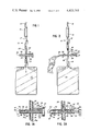
- FIG. 1 is a fragmentary view of a typical system of tubes and capture bag for bladder catheterization, and illustrating use of the coupling of this invention in such a system;
- FIG. 1A is a fragmentary enlarged cross-sectional view of the valve illustrated generally in FIG. 1, and shows the position of the coupling parts when the catheterization system is operating to perform its usual function;
- FIG. 2 is a view similar to that shown in FIG. 1, and showing how the coupling of this invention may be used with a means to capture a mid-stream sample of urine;
- FIG. 2A is a view similar to that shown in FIG. 1A but showing the position of the coupling parts when the system is operating to effect mid-stream sampling of liquid, such as urine, flowing from the body cavity;
- FIG. 3 is a view similar to that shown in FIG. 2 but inverted, and showing how the coupling permits usage to effect back flushing of the catheterized body cavity;
- FIG. 3A is a view similar to FIG. 2A, but inverted, and showing how the back flusher shown in FIG. 3 cooperates with the coupling;
- FIG. 4 is a fragmentary perspective view of details of the coupling shown in FIGS. 1A, 2A and 3A.
- a typical catheterization system is generally illustrated at 10, and same includes an elongated, upstream catheter tube means 12 that is shown provided with an entry aperture 14 through the wall adjacent the end of the tube that is to be lodged in a body cavity.
- an inflatable collar 16 which, after the tube is properly lodged in a body cavity, may be inflated to prevent withdrawal of the tube means 12, as is well known in the art.
- the catheterization system 10 also includes a downstream tube means 18 that leads to and empties into a container for capturing fluid delivered by the system.
- a downstream tube means 18 that leads to and empties into a container for capturing fluid delivered by the system.
- the elongated tube means 18 is formed integrally with a bag 20.
- junction tube between upstream tube means 12 and downstream tube means 18, consisting of a straight length of plastic tubing to which the relatively adjacent ends of the tube means 12 and 18 connect, so that there then exists a through passageway from entry aperture 14 to the interior of capture bag 20.
- a portion of the improvement disclosed herein resides in the use of a novel coupling and valving system for the junction tube referred to above.
- the improved construction shown that includes a tubular cross member 22 with four tubular arms arranged in two opposing pairs.
- a first pair of oppositely extending tubular arms 24 and 26 serve substantially the same function as the usual flow through tube, while the second pair of tubular arms 28 and 30 are at right angles to the axis of tubular arms 24 and 26.
- the free end of either or both arms 24 and 26 may beveled, as seen at 26a to provide for ease in effecting a press fit into the associated resilient tube 18.
- the cross member 22 is an integral molded plastic part.
- the second pair of tubular arms 28 and 30 are axially aligned to serve as projected extensions of each other, and to provide a cylindrical cross passageway in which is positioned an elongated valve member, generally indicated at 32, that is adapted for reciprocating movement substantially between the two positions shown in FIGS. 1A and 2A.
- the valve member 32 preferably of molded plastic, is best seen in FIGS. 1A, 2A and 3A, and includes an elongated, rod-like, cylindrical valve body 34 with a handle, or control knob, 36 at one end thereof.
- the opposite end of valve body 34 may be of reduced exterior diameter relative to the inside diameter of arm 30, and is tubular to provide a tubular end portion 38.
- first diametric bore 40 extending through body 34.
- the bore 40 is spaced axially from control knob 36 such a distance, considering the length of arm 28, that when the knob 36 abuts the terminal edge of tubular arm 28, as seen in FIG. 1A, said diametric bore 40 is located precisely in alignment with the flow pasageway defined by the inner diameter of aligned arms 24 and 26.
- body 34 is selected so as to fit somewhat snugly against the inner resilient wall of the tubular arms 28 and 30 so as to normally effect a seal against leakage of liquid therebetween, yet at the same time being easily selectively movable between the two positions shown in FIGS. 1A and 2A, and also to an intermediate position between said two positions, merely by moving the body 34 axially through manipulation of control knob 36.
- tubular end portion 38 the end of body 34 opposite handle 36 is a tubular end portion 38.
- the bore 39 of tubular end portion 38 extends axially, as shown, from the end of body 34 and terminates at a point spaced from bore 40.
- a second radial bore 42 is provided in body 34, lying parallel to bore 40 but spaced axially from bore 40 away from handle 36, and intersecting bore 39 to provide an angled passageway consisting of bore 42 and bore 39.
- the second radial bore 42 is aligned with the passageway through tubular arm 24, so as to receive liquid from catheter tube means 12 and to direct the liquid laterally through tubular arm 30, thereby effecting a bypass without any need for separating any of the tubes 12 or 18 from the cross member 22.
- the minimum axial spacing of bores 40 and 42 is greater than the inner diameter of tubular arms 24 and 26, so that imperforate body portion 34a could, if desired, be selectively moved to an intermediate position, blocking flow through tubular arms 24 and 26 and through the tubes 12 and 18 to which said arms connect.
- closure cap 46 When the valve body 34 is in the position shown in FIG. 1A, the tubular end of body member 34 may be spaced axially short of the terminal edge 44 of arm 30.
- the cross member 22 may be provided with a separate, or integral, closure cap 46, shown in full lines, for entering into and closing the open end of tubular arm 30. If closure cap 46 is integral with cross member 22, it may be connected to tubular arm 30 through a flexible connection strip 48 which serves as a hinge.
- a tab 47 may be provided on an edge of closure cap 46, located outwardly of tubular arm 30, to provide a means for moving or separating the cap 46 from its closed position, shown in full lines, to be moved to the open position shown in broken lines in FIG. 1A and in full lines in FIG. 2A.
- tubular end of body member 34 could be extended to project outwardly of tubular arm 30, and could be protected from contamination by a slip-over cap (not shown) that would fit onto the tubular end of valve body 34.
- the closure cap 46 serves to prevent contamination from ambient conditions.
- tubular arm 30 When tubular arm 30 is open, as seen in FIG. 2A, the free end of an elongated tube 50 may be introduced into the open end of arm 30, to provide for connection of various accessories to the bypass passageway defined through tubular arm 30.
- the tube 50 may be press fit into arm 30 as seen in FIG. 2A, or may be of a size to enter the arm 30 and to fit onto the reduced tubular end portion 38 of body 34 shown.
- a sample of fluid from the body cavity such as a sample of urine, will flow from the upstream tubing means 12 through passageway 42-39 and through tubular arm 30 to enter tube 50 that is an integral part of a specimen-capturing container, such as bag 51.
- valve 34 When a sufficient sample of fluid has been obtained in bag 51, the valve 34 is moved back to the position shown in FIG. 1A. Thereafter, the tube 50 may be closed, or shut off, with any means known in the art, and withdrawn from arm 30. The catheterization system is now in its normal position for operation without breaking the flow system, or permitting exposure of bore 40 to the possibility of contamination from ambient conditions.
- valve member 32 It is desirable to maintain the bores 40 and 42 in proper radial alignment with the passageways defined by tubular arms 24 and 26. Accordingly, means are provided on the valve member 32 and on the tubular cross member 22 to insure proper alignment at all times.
- the control knob 36 is provided with an elongated arm 52 extending parallel to and spaced from valve body 34 with a radially, inwardly-extending, abutment 54 on arm 52 adjacent the extended end of arm 52.
- the exterior surface of arm 28 is provided with two means for cooperation with arm 52, one to provide a dwell position for abutment 54 and the other to prevent rotation of valve body 34 about its axis.
- the dwell position 56 is provided between a pair of ribs or enlargements 58 provided on the exterior of tubular arm 28.
- the abutment 54 is free of the dwell position 56.
- the abutment 54 enters the dwell position 56 serving as means to hold the valve body in the FIG. 2A position with radial bore 42 in alignment with the tubular arm 24.
- the arm 52 is flexible, and enlargement 54 may be released from the dwell position by merely lifting up on the free end of arm 52 and pushing the valve member 32 to its position illustrated in FIG. 1A.
- the exterior of arm 28 is provided with a pair of spaced ears 64 which bound the plane in which elongated arm 52 is located and is movable, thereby serving to prevent rotation of valve body 34 about its axis.
- valve body 34 With the valve body 34 in the position shown in FIG. 2A, not only can flow from a body cavity be diverted from the interior of the body cavity through the tubular arm 30, but the tubular arm 30 also provides a means through which liquid is back flowed, or instruments may be introduced, through the tubular arm 24 and tube means 12 to the interior of the body cavity.
- a tubular nipple, or nozzle, 60 that is part of a manually actuatable irrigating syringe 62 may be used to force irrigating liquid in a direction opposite to the normal flow.
- This back flow, or irrigating flow is indicated by flow arrows in FIG. 3A.
Abstract
Description
Claims (9)
Priority Applications (1)
| Application Number | Priority Date | Filing Date | Title |
|---|---|---|---|
| US06/360,409 US4423741A (en) | 1980-01-14 | 1982-03-22 | Midstream sampling of catheterized liquid flow from a body cavity and improved coupling therefor |
Applications Claiming Priority (2)
| Application Number | Priority Date | Filing Date | Title |
|---|---|---|---|
| US11159180A | 1980-01-14 | 1980-01-14 | |
| US06/360,409 US4423741A (en) | 1980-01-14 | 1982-03-22 | Midstream sampling of catheterized liquid flow from a body cavity and improved coupling therefor |
Related Parent Applications (1)
| Application Number | Title | Priority Date | Filing Date |
|---|---|---|---|
| US11159180A Continuation | 1980-01-14 | 1980-01-14 |
Publications (1)
| Publication Number | Publication Date |
|---|---|
| US4423741A true US4423741A (en) | 1984-01-03 |
Family
ID=26809054
Family Applications (1)
| Application Number | Title | Priority Date | Filing Date |
|---|---|---|---|
| US06/360,409 Expired - Fee Related US4423741A (en) | 1980-01-14 | 1982-03-22 | Midstream sampling of catheterized liquid flow from a body cavity and improved coupling therefor |
Country Status (1)
| Country | Link |
|---|---|
| US (1) | US4423741A (en) |
Cited By (64)
| Publication number | Priority date | Publication date | Assignee | Title |
|---|---|---|---|---|
| US4572298A (en) * | 1982-11-05 | 1986-02-25 | Hydril Company | Gate valve apparatus and method |
| US4574630A (en) * | 1983-03-04 | 1986-03-11 | Westfalia Separator Ag | Sampler for a milking-system volumeter |
| US4605396A (en) * | 1985-02-25 | 1986-08-12 | Warner-Lambert Company | Gravity flow cassette with rotary valve |
| US4676435A (en) * | 1986-04-01 | 1987-06-30 | Nesland Nickolas B | Sprayer head |
| US4781702A (en) * | 1986-06-20 | 1988-11-01 | Contempo Products, P. Herrli | Three-way connector for liquid exchange |
| WO1988009457A1 (en) * | 1987-05-19 | 1988-12-01 | Hamilton Larry C | Valve |
| US4850980A (en) * | 1987-12-04 | 1989-07-25 | Fisher Scientific Company | I.V. pump cassette |
| US4856506A (en) * | 1988-01-11 | 1989-08-15 | Jinotti Walter J | Apparatus for mouth-to-mouth resuscitation |
| US5060694A (en) * | 1990-11-09 | 1991-10-29 | Fmc Corporation | Filler spool valve |
| US5084035A (en) * | 1990-03-27 | 1992-01-28 | The Kendall Company | Drainage device |
| US5135199A (en) * | 1990-11-07 | 1992-08-04 | Smiths Industries Public Limited Company | Valves and urine bags |
| US5176163A (en) * | 1991-12-11 | 1993-01-05 | Al Hamlan Saleh A | Flow-controlled irrigation system |
| US5232024A (en) * | 1991-05-30 | 1993-08-03 | Eli Williams | Slide-valve manifold |
| US5413115A (en) * | 1993-12-29 | 1995-05-09 | Baldwin; James R. | Biopsy syringe with slide valve |
| US5496287A (en) * | 1994-07-05 | 1996-03-05 | Jinotti; Walter J. | Pulmonary suction catheter |
| WO1996035896A1 (en) * | 1995-05-09 | 1996-11-14 | Ssi Technologies, Inc. | Method and valve for filling fluid system |
| US6511472B1 (en) | 1999-05-21 | 2003-01-28 | Microtherapeutics, Inc. | Interface needle and method for creating a blunt interface between delivered liquids |
| US6626884B1 (en) * | 1998-10-26 | 2003-09-30 | Noble House Group Pty. Ltd. | Sampling in blood collection |
| US20030189069A1 (en) * | 2002-04-03 | 2003-10-09 | Wilson Robert W. | Transverse folding apparatus |
| US20030196699A1 (en) * | 2002-04-19 | 2003-10-23 | Chiang-Pei Chen | Valve for pump |
| US20040171979A1 (en) * | 2002-10-15 | 2004-09-02 | Go Medical Industries Pty, Ltd. | Catheter system and method for delivering medication to the bladder |
| EP1454650A1 (en) * | 2003-03-06 | 2004-09-08 | ZLB Behring GmbH | Transfer device, in particular for medical fluids |
| US20040236305A1 (en) * | 2003-03-05 | 2004-11-25 | Hubert Jansen | Fluid transfer device |
| US20050076964A1 (en) * | 2003-09-09 | 2005-04-14 | Colder Products Company | Connector apparatus and method of coupling bioprocessor equipment to a media source |
| US20050121077A1 (en) * | 2002-04-19 | 2005-06-09 | Chiang-Pei Chen | Bicycle pump valve |
| US20050145276A1 (en) * | 2002-04-19 | 2005-07-07 | Scott Wu | Valve coupling device for pump |
| US20060095019A1 (en) * | 2004-11-02 | 2006-05-04 | Dikeman W C | Urinary catheter |
| US20070057222A1 (en) * | 2003-05-22 | 2007-03-15 | Unomedical A/S | Disposable valve unit for regulating a flow of urine |
| US20070119508A1 (en) * | 2005-11-29 | 2007-05-31 | West Richard L | Fluid Flow Diversion Valve and Blood Collection System Employing Same |
| US20080108955A1 (en) * | 2006-11-02 | 2008-05-08 | Blickhan Bryan J | Flow Controllers |
| US20080108954A1 (en) * | 2006-11-02 | 2008-05-08 | Jean-Marie Mathias | Flow Controllers |
| US20080177201A1 (en) * | 2007-01-20 | 2008-07-24 | Glynis Deadwyler | Urine Specimen Collection Device |
| US20080188770A1 (en) * | 2007-01-29 | 2008-08-07 | Hollister Incorporated | Device and Method for the Collection of a Urine Sample |
| CN100482985C (en) * | 2003-09-09 | 2009-04-29 | 可得制品公司 | Connector apparatus and method of coupling bioprocessing equipment to a media source |
| US20090204080A1 (en) * | 2008-02-12 | 2009-08-13 | Baxter International Inc. | Two-way valve connector |
| US20090218535A1 (en) * | 2008-02-27 | 2009-09-03 | Andres Pasko | Flow controllers for fluid circuits |
| US20100137743A1 (en) * | 2005-07-05 | 2010-06-03 | C. R. Bard, Inc. | Multi-functional and modular urine collection system |
| US20110087164A1 (en) * | 2008-04-01 | 2011-04-14 | Yukon Medical, Llc | Dual container fluid transfer device |
| US20110178425A1 (en) * | 2005-07-05 | 2011-07-21 | C. R. Bard, Inc. | Multi-functional and modular urine collection system |
| US20110178493A1 (en) * | 2008-11-25 | 2011-07-21 | Jms Co., Ltd. | Connector |
| CN102151190A (en) * | 2011-05-12 | 2011-08-17 | 王芳 | Wireless automatic urine specimen collector |
| US20120112113A1 (en) * | 2009-02-04 | 2012-05-10 | Holmes George A | Piston Valve Having Piston With Grooves For Particulate Capture |
| US8240335B1 (en) | 2009-06-12 | 2012-08-14 | Du-Bro Products, Inc. | Fueling valve for fueling a remote control vehicle |
| US20120227845A1 (en) * | 2009-09-11 | 2012-09-13 | Keofitt A/S | Sampling device |
| US20130019867A1 (en) * | 2011-07-20 | 2013-01-24 | General Electric Company | Anesthesia machine and system |
| US20130092253A1 (en) * | 2011-10-12 | 2013-04-18 | Maag Pump Systems Gmbh | Device for distribution of a plastic melt |
| CN103223195A (en) * | 2013-04-15 | 2013-07-31 | 珠海沃姆电子有限公司 | Urine collection device |
| US8556879B2 (en) * | 2008-11-25 | 2013-10-15 | Jms Co., Ltd. | Connector |
| US20140319396A1 (en) * | 2013-04-24 | 2014-10-30 | Hon Hai Precision Industry Co., Ltd. | Valve |
| US20150088034A1 (en) * | 2013-09-25 | 2015-03-26 | Kci Licensing, Inc. | Apparatuses and methods for inline collection of a fluid specimen |
| EP2937135A1 (en) * | 2013-03-15 | 2015-10-28 | Nordson Corporation | Apparatus and method for hydrating a particulate biomaterial with a liquid biomaterial |
| US9713661B2 (en) | 2009-12-23 | 2017-07-25 | C. R. Bard, Inc. | Biological fluid collection system |
| US10420927B2 (en) | 2015-12-04 | 2019-09-24 | Icu Medical, Inc. | Systems, methods, and components for transferring medical fluids |
| US10441206B2 (en) | 2013-09-25 | 2019-10-15 | Kci Licensing, Inc. | Apparatuses and methods for inline collection of a fluid specimen |
| USD874644S1 (en) | 2016-07-19 | 2020-02-04 | Icu Medical, Inc. | Medical fluid transfer system |
| US10667735B2 (en) | 2013-09-25 | 2020-06-02 | Kci Licensing, Inc. | Apparatuses and methods for inline collection of a fluid specimen |
| US11007119B2 (en) | 2009-07-29 | 2021-05-18 | Icu Medical, Inc. | Fluid transfer devices and methods of use |
| US11020541B2 (en) | 2016-07-25 | 2021-06-01 | Icu Medical, Inc. | Systems, methods, and components for trapping air bubbles in medical fluid transfer modules and systems |
| US20210322720A1 (en) * | 2020-04-15 | 2021-10-21 | Stephen J. Hunt | Device for Midstream Sample Collection From a Catheterized Subject and Method and Systems for Use Thereof |
| US11439570B2 (en) | 2011-12-22 | 2022-09-13 | Icu Medical, Inc. | Fluid transfer devices and methods of use |
| US11541171B2 (en) | 2013-11-25 | 2023-01-03 | Icu Medical, Inc. | Methods and systems for filling IV bags with therapeutic fluid |
| US11590057B2 (en) | 2020-04-03 | 2023-02-28 | Icu Medical, Inc. | Systems, methods, and components for transferring medical fluids |
| US20230204137A1 (en) * | 2021-12-28 | 2023-06-29 | Pall Corporation | Fluid connector with slidable member |
| US20240027306A1 (en) * | 2022-01-13 | 2024-01-25 | Children's Hospital of Soochow University | Liquid sample sampling device used in operation |
-
1982
- 1982-03-22 US US06/360,409 patent/US4423741A/en not_active Expired - Fee Related
Cited By (106)
| Publication number | Priority date | Publication date | Assignee | Title |
|---|---|---|---|---|
| US4572298A (en) * | 1982-11-05 | 1986-02-25 | Hydril Company | Gate valve apparatus and method |
| US4574630A (en) * | 1983-03-04 | 1986-03-11 | Westfalia Separator Ag | Sampler for a milking-system volumeter |
| US4605396A (en) * | 1985-02-25 | 1986-08-12 | Warner-Lambert Company | Gravity flow cassette with rotary valve |
| US4676435A (en) * | 1986-04-01 | 1987-06-30 | Nesland Nickolas B | Sprayer head |
| US4781702A (en) * | 1986-06-20 | 1988-11-01 | Contempo Products, P. Herrli | Three-way connector for liquid exchange |
| AU596848B2 (en) * | 1986-06-20 | 1990-05-17 | Contempo Products | Three-way connector for liquid exchange |
| WO1988009457A1 (en) * | 1987-05-19 | 1988-12-01 | Hamilton Larry C | Valve |
| US4850980A (en) * | 1987-12-04 | 1989-07-25 | Fisher Scientific Company | I.V. pump cassette |
| US4856506A (en) * | 1988-01-11 | 1989-08-15 | Jinotti Walter J | Apparatus for mouth-to-mouth resuscitation |
| US5084035A (en) * | 1990-03-27 | 1992-01-28 | The Kendall Company | Drainage device |
| US5135199A (en) * | 1990-11-07 | 1992-08-04 | Smiths Industries Public Limited Company | Valves and urine bags |
| US5060694A (en) * | 1990-11-09 | 1991-10-29 | Fmc Corporation | Filler spool valve |
| US5232024A (en) * | 1991-05-30 | 1993-08-03 | Eli Williams | Slide-valve manifold |
| US5176163A (en) * | 1991-12-11 | 1993-01-05 | Al Hamlan Saleh A | Flow-controlled irrigation system |
| US5413115A (en) * | 1993-12-29 | 1995-05-09 | Baldwin; James R. | Biopsy syringe with slide valve |
| WO1995017848A1 (en) * | 1993-12-29 | 1995-07-06 | Baldwin James R | Biopsy syringe with slide valve |
| US5496287A (en) * | 1994-07-05 | 1996-03-05 | Jinotti; Walter J. | Pulmonary suction catheter |
| WO1996035896A1 (en) * | 1995-05-09 | 1996-11-14 | Ssi Technologies, Inc. | Method and valve for filling fluid system |
| US5971021A (en) * | 1995-05-09 | 1999-10-26 | Ssi Technologies, Inc. | Method and valve for filling fluid system |
| US6626884B1 (en) * | 1998-10-26 | 2003-09-30 | Noble House Group Pty. Ltd. | Sampling in blood collection |
| US6511472B1 (en) | 1999-05-21 | 2003-01-28 | Microtherapeutics, Inc. | Interface needle and method for creating a blunt interface between delivered liquids |
| US20030189069A1 (en) * | 2002-04-03 | 2003-10-09 | Wilson Robert W. | Transverse folding apparatus |
| US20030196699A1 (en) * | 2002-04-19 | 2003-10-23 | Chiang-Pei Chen | Valve for pump |
| US7195030B2 (en) | 2002-04-19 | 2007-03-27 | Chiang-Pei Chen | Bicycle pump valve |
| US7178549B2 (en) | 2002-04-19 | 2007-02-20 | Scott Wu | Valve coupling device for pump |
| US20050121077A1 (en) * | 2002-04-19 | 2005-06-09 | Chiang-Pei Chen | Bicycle pump valve |
| US20050145276A1 (en) * | 2002-04-19 | 2005-07-07 | Scott Wu | Valve coupling device for pump |
| US7150739B2 (en) * | 2002-10-15 | 2006-12-19 | Go Medical Industries Pty, Ltd. | Catheter system and method for delivering medication to the bladder |
| US20040171979A1 (en) * | 2002-10-15 | 2004-09-02 | Go Medical Industries Pty, Ltd. | Catheter system and method for delivering medication to the bladder |
| US8197459B2 (en) | 2003-03-05 | 2012-06-12 | Aventis Behring Gmbh | Self-sealing medical fluid transfer device |
| US20040236305A1 (en) * | 2003-03-05 | 2004-11-25 | Hubert Jansen | Fluid transfer device |
| US20040225274A1 (en) * | 2003-03-06 | 2004-11-11 | Hubert Jansen | Fluid transfer device |
| US7491197B2 (en) * | 2003-03-06 | 2009-02-17 | Csl Behring Gmbh | Fluid transfer device |
| JP2004267776A (en) * | 2003-03-06 | 2004-09-30 | Aventis Behring Gmbh | Transfer device for medical fluid |
| EP1454650A1 (en) * | 2003-03-06 | 2004-09-08 | ZLB Behring GmbH | Transfer device, in particular for medical fluids |
| US7828269B2 (en) * | 2003-05-22 | 2010-11-09 | Unomedical A/S | Disposable valve unit for regulating a flow of urine |
| US20070057222A1 (en) * | 2003-05-22 | 2007-03-15 | Unomedical A/S | Disposable valve unit for regulating a flow of urine |
| US20050076964A1 (en) * | 2003-09-09 | 2005-04-14 | Colder Products Company | Connector apparatus and method of coupling bioprocessor equipment to a media source |
| US7163022B2 (en) | 2003-09-09 | 2007-01-16 | Colder Products Company | Connector apparatus and method of coupling bioprocessing equipment to a media source |
| US20060231137A1 (en) * | 2003-09-09 | 2006-10-19 | Colder Products Company | Connector Apparatus and Method of Coupling Bioprocessing Equipment to a Media Source |
| US7080665B2 (en) | 2003-09-09 | 2006-07-25 | Colder Products Company | Connector apparatus and method of coupling bioprocessor equipment to a media source |
| WO2005027270A3 (en) * | 2003-09-09 | 2005-12-15 | Colder Prod Co | Connector apparatus and method of coupling bioprocessing equipment to a media source |
| CN100482985C (en) * | 2003-09-09 | 2009-04-29 | 可得制品公司 | Connector apparatus and method of coupling bioprocessing equipment to a media source |
| US20060095019A1 (en) * | 2004-11-02 | 2006-05-04 | Dikeman W C | Urinary catheter |
| US20100137743A1 (en) * | 2005-07-05 | 2010-06-03 | C. R. Bard, Inc. | Multi-functional and modular urine collection system |
| US20110178425A1 (en) * | 2005-07-05 | 2011-07-21 | C. R. Bard, Inc. | Multi-functional and modular urine collection system |
| US9216242B2 (en) | 2005-07-05 | 2015-12-22 | C. R. Bard, Inc. | Multi-functional and modular urine collection system |
| US20070119508A1 (en) * | 2005-11-29 | 2007-05-31 | West Richard L | Fluid Flow Diversion Valve and Blood Collection System Employing Same |
| US20080108955A1 (en) * | 2006-11-02 | 2008-05-08 | Blickhan Bryan J | Flow Controllers |
| US20080108954A1 (en) * | 2006-11-02 | 2008-05-08 | Jean-Marie Mathias | Flow Controllers |
| US8043230B2 (en) * | 2007-01-20 | 2011-10-25 | Glynis Deadwyler | Urine specimen collection device |
| US20080177201A1 (en) * | 2007-01-20 | 2008-07-24 | Glynis Deadwyler | Urine Specimen Collection Device |
| US7833169B2 (en) * | 2007-01-29 | 2010-11-16 | Hollister Incorporated | Device and method for the collection of a urine sample |
| WO2008094771A3 (en) * | 2007-01-29 | 2008-10-02 | Hollister Inc | A device and method for the collection of a urine sample |
| JP2010517044A (en) * | 2007-01-29 | 2010-05-20 | ホリスター・インコーポレイテッド | Apparatus and method for collecting urine samples |
| US20080188770A1 (en) * | 2007-01-29 | 2008-08-07 | Hollister Incorporated | Device and Method for the Collection of a Urine Sample |
| AU2008210844B2 (en) * | 2007-01-29 | 2012-11-01 | Hollister Incorporated | A device and method for the collection of a urine sample |
| US20090204080A1 (en) * | 2008-02-12 | 2009-08-13 | Baxter International Inc. | Two-way valve connector |
| US20090218535A1 (en) * | 2008-02-27 | 2009-09-03 | Andres Pasko | Flow controllers for fluid circuits |
| US20110087164A1 (en) * | 2008-04-01 | 2011-04-14 | Yukon Medical, Llc | Dual container fluid transfer device |
| US8821436B2 (en) * | 2008-04-01 | 2014-09-02 | Yukon Medical, Llc | Dual container fluid transfer device |
| US20110178493A1 (en) * | 2008-11-25 | 2011-07-21 | Jms Co., Ltd. | Connector |
| US8556879B2 (en) * | 2008-11-25 | 2013-10-15 | Jms Co., Ltd. | Connector |
| US8506548B2 (en) | 2008-11-25 | 2013-08-13 | Jms Co., Ltd. | Connector |
| US20120112113A1 (en) * | 2009-02-04 | 2012-05-10 | Holmes George A | Piston Valve Having Piston With Grooves For Particulate Capture |
| US8240335B1 (en) | 2009-06-12 | 2012-08-14 | Du-Bro Products, Inc. | Fueling valve for fueling a remote control vehicle |
| US11007119B2 (en) | 2009-07-29 | 2021-05-18 | Icu Medical, Inc. | Fluid transfer devices and methods of use |
| US11806308B2 (en) | 2009-07-29 | 2023-11-07 | Icu Medical, Inc. | Fluid transfer devices and methods of use |
| US9588022B2 (en) * | 2009-09-11 | 2017-03-07 | Keofitt A/S | Sampling device |
| US20120227845A1 (en) * | 2009-09-11 | 2012-09-13 | Keofitt A/S | Sampling device |
| EP2475973B1 (en) * | 2009-09-11 | 2018-02-14 | Keofitt A/S | A sampling device |
| EP3244188A1 (en) * | 2009-09-11 | 2017-11-15 | Keofitt A/S | Use of a sampling device and a method of such use |
| US9713661B2 (en) | 2009-12-23 | 2017-07-25 | C. R. Bard, Inc. | Biological fluid collection system |
| CN102151190A (en) * | 2011-05-12 | 2011-08-17 | 王芳 | Wireless automatic urine specimen collector |
| US20130019867A1 (en) * | 2011-07-20 | 2013-01-24 | General Electric Company | Anesthesia machine and system |
| CN103101126A (en) * | 2011-10-12 | 2013-05-15 | 马格泵系统股份有限公司 | Device for distribution of a plastic melt |
| US20130092253A1 (en) * | 2011-10-12 | 2013-04-18 | Maag Pump Systems Gmbh | Device for distribution of a plastic melt |
| US11439570B2 (en) | 2011-12-22 | 2022-09-13 | Icu Medical, Inc. | Fluid transfer devices and methods of use |
| US11439571B2 (en) | 2011-12-22 | 2022-09-13 | Icu Medical, Inc. | Fluid transfer devices and methods of use |
| US9925305B2 (en) | 2013-03-15 | 2018-03-27 | Nordson Corporation | Apparatus and method for hydrating a particulate biomaterial with a liquid biomaterial |
| US9592321B2 (en) | 2013-03-15 | 2017-03-14 | Nordson Corporation | Apparatus and method for hydrating a particulate biomaterial with a liquid biomaterial |
| EP2937135A1 (en) * | 2013-03-15 | 2015-10-28 | Nordson Corporation | Apparatus and method for hydrating a particulate biomaterial with a liquid biomaterial |
| CN103223195A (en) * | 2013-04-15 | 2013-07-31 | 珠海沃姆电子有限公司 | Urine collection device |
| US20140319396A1 (en) * | 2013-04-24 | 2014-10-30 | Hon Hai Precision Industry Co., Ltd. | Valve |
| US11317839B2 (en) | 2013-09-25 | 2022-05-03 | Kci Licensing, Inc. | Apparatuses and methods for inline collection of a fluid specimen |
| US10441206B2 (en) | 2013-09-25 | 2019-10-15 | Kci Licensing, Inc. | Apparatuses and methods for inline collection of a fluid specimen |
| US10517518B2 (en) * | 2013-09-25 | 2019-12-31 | Kci Licensing, Inc. | Apparatuses and methods for inline collection of a fluid specimen |
| US20150088034A1 (en) * | 2013-09-25 | 2015-03-26 | Kci Licensing, Inc. | Apparatuses and methods for inline collection of a fluid specimen |
| US10667735B2 (en) | 2013-09-25 | 2020-06-02 | Kci Licensing, Inc. | Apparatuses and methods for inline collection of a fluid specimen |
| US11541171B2 (en) | 2013-11-25 | 2023-01-03 | Icu Medical, Inc. | Methods and systems for filling IV bags with therapeutic fluid |
| US10420927B2 (en) | 2015-12-04 | 2019-09-24 | Icu Medical, Inc. | Systems, methods, and components for transferring medical fluids |
| USD948044S1 (en) | 2015-12-04 | 2022-04-05 | Icu Medical, Inc. | Fluid transfer device |
| US11135416B2 (en) | 2015-12-04 | 2021-10-05 | Icu Medical, Inc. | Systems, methods, and components for transferring medical fluids |
| USD1018849S1 (en) | 2015-12-04 | 2024-03-19 | Icu Medical, Inc. | Fluid transfer device |
| US11865295B2 (en) | 2015-12-04 | 2024-01-09 | Icu Medical, Inc. | Systems, methods, and components for transferring medical fluids |
| USD943732S1 (en) | 2016-07-19 | 2022-02-15 | Icu Medical, Inc. | Medical fluid transfer system |
| USD905228S1 (en) | 2016-07-19 | 2020-12-15 | Icu Medical, Inc. | Medical fluid transfer system |
| USD874644S1 (en) | 2016-07-19 | 2020-02-04 | Icu Medical, Inc. | Medical fluid transfer system |
| US11020541B2 (en) | 2016-07-25 | 2021-06-01 | Icu Medical, Inc. | Systems, methods, and components for trapping air bubbles in medical fluid transfer modules and systems |
| US11583637B2 (en) | 2016-07-25 | 2023-02-21 | Icu Medical, Inc. | Systems, methods, and components for trapping air bubbles in medical fluid transfer modules and systems |
| US11951293B2 (en) | 2016-07-25 | 2024-04-09 | Icu Medical, Inc. | Systems, methods, and components for trapping air bubbles in medical fluid transfer modules and systems |
| US11590057B2 (en) | 2020-04-03 | 2023-02-28 | Icu Medical, Inc. | Systems, methods, and components for transferring medical fluids |
| US11717643B2 (en) * | 2020-04-15 | 2023-08-08 | Stephen J. Hunt | Device for midstream sample collection from a catheterized subject and method and systems for use thereof |
| US20210322720A1 (en) * | 2020-04-15 | 2021-10-21 | Stephen J. Hunt | Device for Midstream Sample Collection From a Catheterized Subject and Method and Systems for Use Thereof |
| US20230204137A1 (en) * | 2021-12-28 | 2023-06-29 | Pall Corporation | Fluid connector with slidable member |
| US20240027306A1 (en) * | 2022-01-13 | 2024-01-25 | Children's Hospital of Soochow University | Liquid sample sampling device used in operation |
Similar Documents
| Publication | Publication Date | Title |
|---|---|---|
| US4423741A (en) | Midstream sampling of catheterized liquid flow from a body cavity and improved coupling therefor | |
| US5354267A (en) | Irrigation and suction apparatus | |
| EP0193697B1 (en) | Valve-provided connecting device | |
| US4051852A (en) | Aspirating device | |
| JP4141043B2 (en) | Patient connector | |
| US4106675A (en) | Liquid sampling device | |
| US7063685B2 (en) | Hemostasis valve for a catheter | |
| EP0495419B1 (en) | Device for selectively drawing samples of blood from two sections of a line and for injecting drugs into said blood | |
| US3965910A (en) | Urinary irrigation valve | |
| RU2180600C2 (en) | Medical connector | |
| US6581906B2 (en) | Connector having an inner displacement member | |
| US5919146A (en) | Urine sampling and drainage device | |
| US7581559B2 (en) | Check valve for a fluid administration system | |
| CA1037809A (en) | Port means for a liquid transport system | |
| US6032926A (en) | Hose coupling for a medical transfer system | |
| US20170224977A1 (en) | Urinary catheter irrigation device and method of irrigating a urinary catheter | |
| US5725515A (en) | Urine sampling and bladder drainage system | |
| US6240960B1 (en) | Back flush valve for one-way flush of drainage catheters | |
| JP2022521967A (en) | Valves for artificial bladder instruments | |
| SE439110B (en) | RECYCLABLE CATETER DEVICE | |
| US5261416A (en) | Sealed catheter device | |
| JP2004537381A (en) | Male lure with valve | |
| JP2008132340A (en) | Improved connecting device for catheters, and equipment and systems for perfusing and draining liquid in the human body | |
| EP2683435B1 (en) | Devices for aseptic irrigation, urine sampling, and flow control of urine from a catheterized bladder | |
| US3977409A (en) | Tube valve |
Legal Events
| Date | Code | Title | Description |
|---|---|---|---|
| AS | Assignment |
Owner name: PLASCO, INC., 4080 MORRISON DRIVE, GURNEE, ILL. 60 Free format text: ASSIGNMENT OF ASSIGNORS INTEREST.;ASSIGNOR:LEVY, NORMAN;REEL/FRAME:004169/0914 Effective date: 19830913 |
|
| FEPP | Fee payment procedure |
Free format text: SURCHARGE FOR LATE PAYMENT, PL 96-517 (ORIGINAL EVENT CODE: M176); ENTITY STATUS OF PATENT OWNER: LARGE ENTITY |
|
| MAFP | Maintenance fee payment |
Free format text: PAYMENT OF MAINTENANCE FEE, 4TH YEAR, PL 96-517 (ORIGINAL EVENT CODE: M170); ENTITY STATUS OF PATENT OWNER: LARGE ENTITY Year of fee payment: 4 |
|
| FEPP | Fee payment procedure |
Free format text: MAINTENANCE FEE REMINDER MAILED (ORIGINAL EVENT CODE: REM.); ENTITY STATUS OF PATENT OWNER: LARGE ENTITY |
|
| LAPS | Lapse for failure to pay maintenance fees | ||
| FP | Lapsed due to failure to pay maintenance fee |
Effective date: 19911229 |
|
| STCH | Information on status: patent discontinuation |
Free format text: PATENT EXPIRED DUE TO NONPAYMENT OF MAINTENANCE FEES UNDER 37 CFR 1.362 |