US4385357A - Water treatment system and control therefor - Google Patents
Water treatment system and control therefor Download PDFInfo
- Publication number
- US4385357A US4385357A US05/896,568 US89656878A US4385357A US 4385357 A US4385357 A US 4385357A US 89656878 A US89656878 A US 89656878A US 4385357 A US4385357 A US 4385357A
- Authority
- US
- United States
- Prior art keywords
- regeneration
- valve
- sequence
- water
- predetermined
- Prior art date
- Legal status (The legal status is an assumption and is not a legal conclusion. Google has not performed a legal analysis and makes no representation as to the accuracy of the status listed.)
- Expired - Lifetime
Links
- 0 C*C(C1)=C(*)C1c1ccccc1 Chemical compound C*C(C1)=C(*)C1c1ccccc1 0.000 description 1
Images


Classifications
-
- G—PHYSICS
- G05—CONTROLLING; REGULATING
- G05D—SYSTEMS FOR CONTROLLING OR REGULATING NON-ELECTRIC VARIABLES
- G05D21/00—Control of chemical or physico-chemical variables, e.g. pH value
- G05D21/02—Control of chemical or physico-chemical variables, e.g. pH value characterised by the use of electric means
-
- B—PERFORMING OPERATIONS; TRANSPORTING
- B01—PHYSICAL OR CHEMICAL PROCESSES OR APPARATUS IN GENERAL
- B01J—CHEMICAL OR PHYSICAL PROCESSES, e.g. CATALYSIS OR COLLOID CHEMISTRY; THEIR RELEVANT APPARATUS
- B01J47/00—Ion-exchange processes in general; Apparatus therefor
- B01J47/14—Controlling or regulating
-
- B—PERFORMING OPERATIONS; TRANSPORTING
- B01—PHYSICAL OR CHEMICAL PROCESSES OR APPARATUS IN GENERAL
- B01J—CHEMICAL OR PHYSICAL PROCESSES, e.g. CATALYSIS OR COLLOID CHEMISTRY; THEIR RELEVANT APPARATUS
- B01J49/00—Regeneration or reactivation of ion-exchangers; Apparatus therefor
- B01J49/80—Automatic regeneration
- B01J49/85—Controlling or regulating devices therefor
-
- C—CHEMISTRY; METALLURGY
- C02—TREATMENT OF WATER, WASTE WATER, SEWAGE, OR SLUDGE
- C02F—TREATMENT OF WATER, WASTE WATER, SEWAGE, OR SLUDGE
- C02F1/00—Treatment of water, waste water, or sewage
- C02F1/42—Treatment of water, waste water, or sewage by ion-exchange
-
- C—CHEMISTRY; METALLURGY
- C02—TREATMENT OF WATER, WASTE WATER, SEWAGE, OR SLUDGE
- C02F—TREATMENT OF WATER, WASTE WATER, SEWAGE, OR SLUDGE
- C02F2209/00—Controlling or monitoring parameters in water treatment
- C02F2209/005—Processes using a programmable logic controller [PLC]
- C02F2209/006—Processes using a programmable logic controller [PLC] comprising a software program or a logic diagram
-
- C—CHEMISTRY; METALLURGY
- C02—TREATMENT OF WATER, WASTE WATER, SEWAGE, OR SLUDGE
- C02F—TREATMENT OF WATER, WASTE WATER, SEWAGE, OR SLUDGE
- C02F2303/00—Specific treatment goals
- C02F2303/16—Regeneration of sorbents, filters
Definitions
- the present invention relates to water treating systems and, more particularly, to a water treatment system, the efficacy of which may be periodically regenerated, and an electronic control for such a treatment system.
- Water treatment systems may typically include a treatment tank which is filled with a resin material, such as zeolite, forming a resin bed through which untreated water is directed.
- a resin material such as zeolite
- hard water passing through the treatment bed will experience an ion exchange process in which the sodium ions are exchanged for hard metal ions in the water.
- the water treating efficacy of the zeolite bed will be gradually reduced and, after a predetermined quantity of water has been treated, the ion exchange process will no longer take place. It is possible to generate the zeolite bed, however, by passing a salt brine solution through the bed to reverse the ion exchange process.
- the maximum period of time between successive regeneration operations is dependent upon both the hardness of the water and the quantity of water which is treated.
- the brine which is used during regeneration is stored in a brine tank to which salt is periodically added. Should the quantity of salt in the brine tank be reduced substantially without additional salt being added, the brine solution used for regeneration may be sufficiently concentrated to restore the water treating efficacy of the resin bed.
- Prior art control devices made no provision for altering the regeneration cycle to compensate for this condition. Additionally, refilling the brine tank after regeneration has typically been accomplished by applying water through a control valve arrangement for a predetermined period of time. Should this valve arrangement malfunction, the brine tank might overflow. No provision has been made in prior art systems to detect or correct this condition.
- a control system for controlling regeneration of a water softener system is disclosed in U.S. patent application Ser. No. 779,097, filed Mar. 18, 1977, by Davis, and assigned to the assignee of the present invention.
- the Davis application discloses an electrical water softener control which includes a flow meter in the water line providing a pulse output of a frequency proportional to the flow rate of the water treated by the softener.
- a counter circuit initiates regeneration at a predetermined time of day next occurring after a quantity of water equal to the treatment capacity of the system, less an average 24-hour supply, has been treated. The circuit will also initiate regeneration immediately, should a quantity of water equal to the treatment capacity of the system be treated.
- a water treatment system includes a water treatment tank containing a resin bed through which water is passed for treatment thereof during normal operation of the treatment system.
- a brine tank contains a brine solution which, when passed through the resin bed, regenerates the treatment effectiveness of the bed.
- a plurality of electrically actuatable valve means direct water through the treatment tank during normal operation of the treatment system and direct brine solution through the treatment tank in a regeneration operation.
- the water treatment system control includes a means for manually entering control data, display means for displaying data, sensor means for sensing the volume of water treated by the water treatment system, and controller circuit means.
- the controller circuit means is responsive to the means for manually entering control data and to the sensor means.
- the controller circuit means is connected to display data on the display means and provides electrical control signals to the plurality of electrically actuatable valve means.
- the sequence, duration, and time of occurrence of the electrical control signals applied to the valve means are determined by the control data entered through the means for manually entering control data.
- the controller circuit means may include means, responsive to the sensor means, for accumulating the volume of water treated by the treatment system and for disabling the treatment system when a predetermined volume of water has been treated.
- the controller circuit means may also include a means for providing display signals to the display means such that a plurality of entry code indicia are sequentially displayed by the display means, with the control data associated with each of the entry code indicia being displayed directly after display of the respective entry code indicia.
- the means for manually entering control data comprises a plurality of slew control switches, each of which is associated with one digit in a multi-digit display arrangement. Actuation of a slew control switch will change the control data digit associated therewith.
- One of the plurality of entry code indicia may have associated therewith control data related in value to the control data associated with the remainder of the plurality of entry code indicia.
- the control data associated with the one of the plurality of entry code indicia may be a check sum which is compared with the sum of the balance of the control data associated with the remainder of the plurality of entry code indicia to detect an error in entry of control data.
- the controller circuit means also includes means for counting the number of times that the treatment system is regenerated.
- a bypass water line bypassing the water treatment tank includes a motor-powered bypass valve and means for actuating the bypass valve when the water treatment system is disabled.
- the controller circuit means may further comprise a memory which provides a back-up control data for use by the controller circuit means as required, should control data not be entered by the means for manually entering control data.
- An electrical overflow probe in the brine tank detects when the level of brine solution in the brine tank exceeds a predetermined overflow level and provides an overflow signal to the controller circuit means which results in initiation of a regeneration operation. Should the overflow signal continue to be provided to the controller circuit means for more than a specified period of time after the regeneration operation is initiated, the water treatment system will be disabled.
- An electrical low salt probe may also be provided in the brine tank for detecting when the level of brine solution in the brine tank is less than a predetermined low salt level and for providing a low salt signal to the controller circuit means. The controller circuit means will provide a low salt display signal to the display means upon receipt of the low salt signal, such that a low salt warning display is provided until the low salt signal is terminated.
- controller circuit means will control the regeneration operation next occurring after termination of the low salt signal such that a greater quantity of brine solution is passed through the resin bed than during the previous regeneration operation.
- the control may further include an alternate power source means, including a battery, for providing power upon failure of the external alternating current power source.
- a water treatment system and a control therefor which may be programmed by an operator such that the sequencing, duration, and occurrence time of electrical control signals provided to controlling valve mechanisms in the system may be programmed; to provide such a system and control which are responsive to operation of the treatment system for controlling regeneration thereof; to provide such a system and control which senses fluid levels in the system and provides modification of system operation in response to inappropriate fluid levels; to provide such a system and control in which control data may be simply entered and modified; and to provide such a system and control which will sense the system operation and disable the system after predetermined system operation limits have been reached.
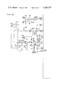
- FIG. 1 is a schematic diagram illustrating the flow of water through the system and subsequent regeneration of the system
- FIGS. 2a-2d when assembled with FIG. 2a above FIG. 2c and FIG. 2b above FIG. 2d with FIGS. 2a and 2c to the left of FIGS. 2b and 2d, is an electrical schematic representation of circuitry forming a portion of the control of the present invention.
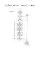
- FIGS. 3-17 comprise a flow chart illustrating the sequence of steps undertaken by a micro-computer control in the control of the present invention.
- FIG. 1 illustrates the water treatment system of the present invention.
- the treatment system includes a treatment tank 20, containing a resin bed 22 through which water is passed for treatment thereof during normal operation of the treatment system.
- a brine tank 24 contains a brine solution 26 which, when passed through the resin bed 22, regenerates the treatment effectiveness of the bed 22.
- a plurality of electrically actuatable valves, including solenoid actuated valves 28 and 30, direct water through the treatment tank 20 during normal operation of the treatment system and direct brine solution through the treatment tank 20 during a regeneration operation.
- a treatment system control includes a sensor means 31 such as an electrical flow meter, for sensing the volume of water treated by the water treatment system.
- the control additionally includes an electrical overflow probe means 32 for detecting when the level of brine solution in the brine tank 24 exceeds a predetermined overflow level and for providing an overflow signal on line 34 in response thereto.
- An electrical low salt probe means 36 is also provided in the brine tank 24 for detecting when the level of brine solution in the brine tank is less than a predetermined low salt level and for providing a low salt signal on line 38.
- a quantity of salt 40 in the brine tank 24 assures a sufficient salt concentration in the brine solution.
- the treatment tank 20 is shown in FIG. 1 as contained within the brine tank 24. It will be appreciated that the treatment tank 20 may be taken out of the brine tank 24 and placed at a remote location as long as the water lines between the two tanks are properly connected.
- raw, untreated water is received on line 42. Since solenoid valves 28 and 30 are not actuated, the untreated water flows through line 44, valve 46, line 48, and into the treatment tank 20.
- the resin bed 22 in the tank 20 may typically be a zeolite resin bed which, through the well known ion exchange process discussed previously, softens the water.
- Outlet distributor 50 receives the treated water which then flows through line 52, valve 54, line 56, and outlet line 58.
- solenoid 1 When regeneration is desired, solenoid 1 is actuated, thus placing valve 28 into its left-most position and initiating a backwash cycle.
- the softening system is bypassed via valve 28 and check valve 60.
- untreated water is supplied from line 58 via line 56, valve 55, and line 52 to the outlet distributor 50 in the water treatment tank 20.
- This backwash process loosens the resin bed and facilitates regeneration of the zeolite.
- the water then flows out of line 48 and, via pilot-actuated valve 46, to line 62. Pilot-actuated valve 64 will also be actuated and will pass this water through the backwash flow control valve 66 to the drain line 68.
- solenoid 2 will also be energized, thus actuating valve 30 into its left-most position.
- the brining cycle will now begin in which a brine solution 26 from the brine tank 24 will be supplied to the water treatment tank 20.
- solenoid 2 actuates valve 30, water flow through jet 70 and check valve 72 siphons the brine solution out of the brine tank 24 via air check valve 74.
- Air check valve 74 includes a float 76 and is provided to insure that line 78 is closed when the fluid level in the brine tank drops to the level of the valve seating arrangement 80. Brine solution is siphoned through line 78 and is provided through check valve 82 to line 84.
- the brine solution passes through line 48, treatment tank 20, line 52 and, since pilot-actuated valve 54 is actuated, the brine solution flows into drain line 68. After the air check valve 74 closes, siphoning is terminated. Water continues to flow from line 42 through jet 70 and tank 20, thus providing a slow rinse cycle.
- Double pilot-actuated valve 86 is spring biased such that it will remain normally closed when receiving pilot pressure on both sides. If solenoid 1 is now deenergized, however, valve 28 will be de-energized, thus removing the pilot pressure from the right side of valve 86. Valve 86 will therefore be pilot-actuated open and, since it is across jet 70, the siphoning effect of the jet will be terminated. Additionally, the pilot pressure will be removed from line valve 46 with the result that water will begin flowing through line 48 into tank 20. A fast rinse cycle is thus initiated. Since, at this point, valve 30 is still actuated, pilot-actuated valve 54 continues to supply the output from tank 20 to the drain line 68.
- valve 30 water is supplied through valve 30, valve 86, control valve 88, to line 78 such that brine tank 24 is refilled with water.
- Valve 86 controls the flow of water to the brine tank 24, insuring that the proper quantity of water is added to the brine tank.
- solenoids 1 and 2 are de-energized and the water treatment system returns to its normal operational mode in which water passes from line 42 to outlet 58 via the treatment tank 20.
- a motor-powered bypass valve 90 is provided in a bypass water line 92.
- the bypass valve is actuated by an electrical control signal applied to line 94.
- Line 96 provides an electrical indication to the system control of whether the bypass valve 90 is open or closed.
- FIGS. 2a-2d illustrate schematically the water treatment system control of the present invention.
- Slew switches S1, S2, S3, and S4 provide a means for manually entering control data into the system control.
- a display means for displaying data includes a four-digit, seven-segment display 98 with the anode of each LED segment in each of the digits connecting to a respective one of transistors Q1-Q8.
- the electrical flow meter 31 (FIG. 1) is shown diagrammatically as a switch in FIG. 2.
- This flow meter may be of the type in which a turbine in the water line includes a magnet which passes a reed switch repeatedly as the turbine is rotated by the flow of water through the line. The number of switch closures, therefore, is proportional to the volume of water which passes through the line.
- Switch 100 is associated with the bypass valve 90 (FIG. 1) and applies a signal to line 96 indicating whether the valve 90 is open or closed.
- the control of FIG. 2 includes a controller circuit means which is responsive to the means for manually entering control data and to the sensor means, and is connected to display data on the display means.
- the controller circuit means provides electrical control signals to the plurality of electrically actuatable valve means. The sequence, duration, and time of occurrence of the electrical control signals are determined by control data entered through the means for manually entering control data.
- the controller circuit means advantageously includes a microcomputer MK 3870, available from Mostek Corporation, Carrollton, Texas.
- Output lines from the micro-computer include lines PO-0, PO-1, PO-2, and PO-3.
- line PO-0 goes high, transistor Q9 will be switched on, causing the gate input of the associated triac to go high. This will turn on the triac, permitting current flow through the coil 1 and energizing the solenoid-controlled valve 28 (FIG. 1).
- a high signal on lines PO-1 and PO-3 will result in energization of the coil 2, associated with valve 30, and the bypass motor coil associated with the valve 90, respectively.
- the PO-2 output provides an optional control signal which may be used to control additional solenoid-actuated valves which could be added to the water treatment system of FIG. 1.
- the MK 3870 micro-computer provides further additional output lines which are not used in the illustrated control but which might be used to control a modified version of the disclosed treatment system.
- Switch 101 is the reed switch which is repetitively closed and opened by a magnet mounted on the turbine in the flow meter 31. Pulses applied to line 102 will therefore set the flip-flop 104 such that the input P4-3 will go high. The DDl low-going pulses which are applied to the upper NAND gate reset the flip-flop 104.
- the micro-computer accumulates the pulses applied to input P4-3 and thus keeps track of the total volume of water treated since the installation of the water treatment system.
- the control circuit of the present invention also accumulates the pulses received on line P4-3 to keep track of the volume of water treatment between successive regeneration cycles.
- the bypass switch 100 provides a signal to input P1-0 via a monostable multi-vibrator indicating whether bypass valve 90 is opened or closed.
- An optional repeat switch 106 may be manually actuated to provide a signal to input P1-3 via a monostable multi-vibrator causing the system to return to its initial regeneration step.
- a probe input receives the output signal from the overflow electrical probe 32 on line 34 and applies it via a monostable multi-vibrator to input P1-2.
- the output of the low salt probe 36 on line 38 is applied to the input P1-6 via a monostable multi-vibrator.
- An optional probe input, labeled PROBE 1 may be applied to the input line P1-1 via a monostable multi-vibrator. This optional probe may be used, for instance, to detect a fluid level in a water treatment system of a different design.
- the signal applied to this input may be used to control operation of the optional control line P0-2.
- Inputs P1-4 and P1-5 are shown as grounded. Input P1-4 is grounded when the system operates on 60 cycle power. The ground will be removed from the P1-4 input when a 50 cycle power supply is used. The system operates in what is termed a "lock out mode" when the P1-5 input is grounded. When the number of pulses received from the sensor switch 32 indicates that one million gallons of water have been treated, the water treatment system will then shut down, the bypass valve will be actuated, and a CALL display presented on the display 98, if the lock out mode has been selected.
- a RESET is presented at pin 39 when the control system is initially installed and turned on or when power is reapplied after a power outage.
- a power supply circuit includes a transformer 110 which steps down the 120 volt AC line current received through connector 112 and provides a 12 volt AC output across capacitor C9.
- Capacitor C11 and diode CR1 provide a voltage V LED which powers the display 98.
- the diode CR3 and capacitor C16 provide a rectified potential to a power regulator circuit, including transistor Q14 and zener diode 114. Zener diode 114 is reverse biased such that the base of Q14 is held at approximately 5.6 volts. The emitter of transistor Q14 will therefore provide a 5 volt potential, V cc , which is used as a biasing potential in various portions of the control circuit.
- Resistor R23 and capacitor C8 filter the alternating current signal across capacitor C9 and provide this signal to monostable multi-vibrator 116.
- the output of trigger 116 termed EXT. INT., is an external interrupt signal which is used by the micro-computer MK 3870 for time-keeping purposes.
- diode CR4 will no longer be reverse biased and the 9.3 volt battery 118 will provide sufficient power to the regulator circuit to power the micro-computer for approximately a four-hour period.
- the outputs P5-0, P5-1, P5-2, P5-3, P5-4, P5-5, and P5-6 provide gating signals to transistors Q8-Q2, respectively.
- the associated transistor When a high signal appears at one of the P5-0-P5-6 outputs, the associated transistor will be switched on, resulting in application of voltage V LED to the inputs A-G of display 98.
- Each of the four digits displayed by display 98 is made up of seven bars which are illuminated individually by seven light-emitting diodes.
- the seven inputs A-G are each connected to the anode of one light-emitting diode associated with each digit.
- the outputs P4-4, P4-5, P4-6, and P4-7 are connected to the DD1, DD2, DD3, and DD4 inputs of display 98.
- the DD1 input goes low, the cathodes of all of the light-emitting diodes associated with the least significant digit are grounded.
- the DD1 signal is also applied to the reset input of the flip-flop 104.
- the DD2 input goes low, the cathodes of all of the light-emitting diodes associated with the next to the least significant digit are grounded.
- the DD3 input goes low, the cathodes of all of the light-emitting diodes associated with the second most significant digit are grounded.
- Switches S1-S5 provide the means for manually entering control data.
- the recall/enter switch S5 When the recall/enter switch S5 is depressed, the first of a plurality of entry code indicia will be displayed on display 98.
- switch S5 When switch S5 is again closed, the control data associated with the first entry code indicia will then be displayed. Closing switch S5 again will result in the second entry code indicia being displayed. A subsequent closure of switch S5 will result in the control data associated with the second entry code indicia being displayed.
- switch S5 By repeated closure of switch S5, an operator can cause to be displayed in sequence each of a plurality of entry code indicia with the control data associated with each of the entry code indicia being displayed directly after display of the respective entry code indicia.
- switches S1-S4 When control data is being displayed, it is possible to change the value of this data by depressing switches S1-S4.
- switch S1 When switch S1 is depressed, the least significant digit will quickly step upward through all possible values of the digit.
- switch S1 When the digit reaches the value desired by the operator, switch S1 is released and the desired data change is complete.
- switches S2-S4 may be held closed until the desired control data values appear on the display in the digit positions associated with each of the switches.
- Bypass switch S6 is provided to permit manual control of the bypass valve 90.
- Switch S7 when closed, will initiate a regeneration operation.
- Inputs P4-0 and P4-1 are grounded upon closure of switches S1-S7.
- the 3870 micro-computer notes the time at which this grounding occurs and translates this into information indicating closure of the respective switch S1-S7.
- the display When power is initially turned on after installation of the system or when power is reapplied after a power outage of sufficient duration such that the battery 118 is discharged, the display will flash 88 88 at a one-second rate.
- a standard regeneration schedule which is stored in the micro-computer in a read only memory (ROM) will be transferred to a random access memory (RAM) and used to control a regeneration cycle which is immediately initiated, assuming that the bypass valve is not opened.
- the micro-computer monitors the volume of water treated by the treatment system and, unless otherwise programmed, initiates a regeneration operation every 200 gallons.
- the probe 32 is monitored and if this probe is in contact with brine solution in the brine tank, solenoids 1 and 2 are energized for two minutes, causing brine to be siphoned out of the brine tank. Should the probe 32 remain in contact with the brine solution for two minutes, the treatment system will be bypassed by the bypass valve 90 and the system will thereafter be disabled until serviced.
- control data is entered via the switches S1-S5 as discussed above. This control data will specify the manner in which the system is to be operated and will replace the control data which was initially brought forward from the ROM to the RAM when power was turned on.
- the system is programmed by means of switches S1-S5. Initially the recall/enter switch S5 is closed until the entry code indicia ECO1 is displayed. Subsequent closure of the switch S5 results in the time of day being displayed. The colon will flash on the display when the time indicated is PM. The time is set by means of switches S1-S4.
- recall/enter switch S5 is momentarily closed and the entry code indicia ECO2 is displayed. Subsequent closure of the switch S5 results in the time of regeneration being displayed. The operator will now actuate switches S1-S4 until the desired time of regeneration is shown on the display 98.
- the next entry code indicia, ECO3 is associated with the first four days of the week.
- the most significant digit is associated with Monday, the second most significant digit associated with Tuesday, the third most significant digit associated with Wednesday, and the least significant digit associated with Thursday. If a 1 is displayed in a digit position, regeneration will occur in the morning of the day associated therewith. If a 2 is displayed in a digit position, regeneration is to occur in the afternoon of the day associated with the digit position.
- the display of 3 in a digit position indicates that regeneration is to occur during both the morning and afternoon of the day associated with the digit position. Display of a 0 will indicate that no regeneration is to occur on this day.
- Entry code indicia ECO4 is associated with control data defining whether regeneration will occur during the last three days of the week and also with the number of the present day of the week.
- the most significant digit is associated with Friday, the second most significant with Saturday, and the third most significant digit is associated with Sunday.
- the least significant digit is a number defining the present day of the week, with Monday being 1, Tuesday being a 2, Wednesday being a 3, etc.
- entry code indicia ECO5 may not be programmed. This data is the total number of gallons ( ⁇ 100) which have been treated by the system since the system was installed. Similarly, entry code indicia ECO6 is associated with the total number of regeneration cycles which have occurred since the installation of the treatment system. Although these values may not be altered by means of the switches S1-S5, the value of data associated with ECO5 and ECO6 will be displayed. These entry code indicia will provide a means of checking the usage of the system and, therefore, may prove particularly advantageous in situations where the water treatment system is rented with the rental based upon usage.
- the entry code indicia ECO7 is associated with control data specifying the treatment capacity of the system between regeneration cycles.
- the entry code indicia ECO8 is associated with control data specifying the average quantity of water treated by the system each day. In one programmed regeneration mode, the system will regenerate at the specified time of day next following the determination by the control circuit that a volume of water equal to the capacity of the system, less a 24-hour supply, has been treated since the previous regeneration operation.
- the control data associated with entry code indicia ECO8 is a number other than 0, the regeneration of the water treatment system will be solely on this basis.
- the control data associated with entry code indicia ECO8 is 0, on the other hand, regeneration will occur according to the day schedule specified by the control data associated with ECO3 and ECO4.
- Entry code indicia ECO9 is associated with control data providing two separate control functions.
- the left two digits provide a check sum in hexadecimal form.
- the hexadecimal sum of the left-most two digits in the control data associated with entry codes ECO7-ECO13, excluding ECO9, will equal the left-most two digits of the control data associated with entry code indicia ECO9 when the system is properly programmed. This will insure that the control data has been properly entered.
- a service man may place hexadecimal number FF in the two left-most digits of the control data associated with entry code indicia ECO9.
- the number appearing in the data associated with ECO9 will equal in hexadecimal form the sum of the left-most two digits of ECO7-EC13, as required. Subsequent programming of the system, such as after a power failure of substantial duration, will be effective only when the check sum and other control data are properly entered.
- the two least significant digits of the control data associated with entry code indicia ECO9 indicate in hexadecimal form the number of pulses per gallon received from the turbine flow meter via line 102 and flip-flop 104.
- the number of pulses per gallon may be set at an artificial value such that lock out will occur after treatment of less than one million gallons.
- Entry code indicia EC10 specifies outputs to the various control lines during the first step of the regeneration process.
- the control data associated with entry code indicia EC10 will be a four-digit hexadecimal number.
- the 3870 micro-computer will convert this hexadecimal number into a corresponding 16 bit binary number.
- the eight most significant binary bits specify the regeneration interval time period during which the initial regeneration step associated with EC10 will occur.
- the ninth most significant bit specifies whether the regeneration interval is given in minutes or seconds, with a 1 indicating minutes and a 0 indicating seconds.
- the seven least significant binary bits indicate the output states of the outputs PO-0 through PO-6 with a 1 indicating that these outputs are to be high and a 0 indicating that the outputs are to be low.
- the subsequent entry code indicia EC11-EC18 are associated with successive regeneration steps. Each of these indicia is associated with control data providing both the regeneration interval time for the step and the output states of the control outputs.
- the water treatment system control of the present invention will initiate a regeneration operation based upon the control data which is entered into the controller circuit. If the data associated with entry code indicia ECO8 is 0, the system will operate in a day regeneration mode in which regeneration will occur on the days specified by the indicia associated with entry code indicia ECO3 and ECO4, at the time of day specified by entry code indicia ECO2. If, prior to a regeneration operation, the total gallon capacity of the system, as set by the control data associated with entry code indicia ECO7, is exceeded, the regeneration operation will be initiated immediately, regardless of the day or time. If the system is operated in the day regeneration mode with the P1-5 input grounded, when the total accumulated gallons reaches one million, the control will switch into the bypass mode, provide a CALL service display on display 98, and terminate operation of the water treatment system.
- control data other than 0000 is entered for entry code indicia ECO8, a number indicating the average 24-hour water usage, regeneration will occur when the total gallon capacity (ECO7) minus the 24-hour usage (ECO8) is exceeded, and the time for regeneration is correct. If the total gallon capacity (ECO7) is exceeded prior to the time of day associated with ECO2, regeneration will be initiated immediately.
- FIG. 3 illustrates the main line program which consists of a plurality of sub-routines, each sub-routine being represented by a block.
- the micro-computer will then sequentially go through the PCT test routine, the GALLON COUNT routine, the AC LOSS IN REGEN routine, the BYPASS routine, the DISPLAY MANAGER routine, the DATA ENTRY routine, the CHECK SUM routine, the ERROR HANDLING routine, the GO TO REGEN routine, the REGENERATION routine, and the SALT CHECK routine.
- the micro-computer will thereafter continuously cycle through all of the routines, with the exception of the POWER ON RESET routine, during operation of the treatment system.
- An INTERNAL INTERRUPT routine and an EXTERNAL INTERRUPT routine are shown diagrammatically as being entered after the SALT CHECK routine. Actually, each of these routines is entered from anywhere in the MAIN LINE routine.
- the INTERNAL INTERRUPT routine is entered every two milliseconds, regardless of the routine being handled by the micro-computer. This routine drives the display and operates the slew switches for the entry of control data.
- the INTERNAL INTERRUPT routine also notes closure of the reed switch associated with the flow meter. When the INTERNAL INTERRUPT routine is terminated, the micro-computer returns to the main line at the point at which it left the main line.
- the EXTERNAL INTERRUPT routine performs a time-keeping function by monitoring 60 Hertz power line fluctuations. If the power from the 60 Hertz supply is lost, the INTERNAL INTERRUPT routine will take over the time-keeping function, as shown by the dashed line.
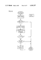
- FIGS. 4-17 disclose the details of each of the sub-routines shown in FIG. 3.
- lines between blocks have been eliminated in some cases and letters or numbers used to indicate the sequence of steps undertaken in the sub-routines.
- Each letter and number so used refers only to similarly indicated points within the individual sub-routine. Transition from one sub-routine to the next is accomplished only through START, END OF ROUTINE, and EXIT blocks.
- FIG. 4 illustrates the POWER ON RESET routine. This routine will initially clear all the output lines. It will then bring forward the initial regeneration program from the read only memory and insert it into a random access memory. As discussed above, this initial regeneration program insures that regeneration will occur, typically on a relatively conservative basis, even if the micro-computer is not programmed by manual entry of control data. The timer and interrupt controls are then enabled.
- the main line program then goes into a PRINTED CIRCUIT BOARD (PCB) TEST routine which is illustrated in FIG. 5.
- PCB PRINTED CIRCUIT BOARD
- FIG. 6 illustrates the GALLON COUNT routine.
- This routine keeps track of the switch closures experienced by the reed switch associated with the flow meter 31 in the outlet line of the water treatment system.
- the switch count reaches a total equal to the weighting function which has previously been entered (ECO9)
- the counters keeping track of the volume of water treated since the previous regeneration and the total volume of water treated since installation of the system will be incremented.
- the gallon count accumulated since installation of the system equals one million and, further, the system is operating in a lock out mode, discussed above, a bypass of the treatment system will occur and the system will cease to operate.
- the display will also display a CALL indicia on display 98, indicating that a service man should be called.
- FIG. 7 illustrates the AC LOSS IN REGEN routine.
- This sub-routine will only be entered when the system is in the regeneration mode of operation and, simultaneously, the AC power supply for the system is interrupted.
- This sub-routine turns off all the drives, and sets a GO TO REGEN flag so that when the AC power is reapplied to the system, a new regeneration cycle will occur. If this were not done, the water treatment system might not be fully regenerated when power was reapplied to the system but the control circuitry would not sense this condition. With the GO TO REGEN flag set, however, the regeneration operation will be reinitiated as soon as power is reapplied to the system.
- FIG. 8 illustrates the BYPASS routine.
- the bypass switch switch 100 (FIG. 2)
- the bypass switch switch 100 (FIG. 2)
- the sub-routine then continues at the point indicated at 1. If the TURN-ON BYPASS flag is set and the bypass switch 100 is closed, the bypass operation will be complete and therefore, the bypass motor turned off, the TURN-ON BYPASS flag reset, and the TURN-OFF BYPASS flag reset. If the bypass switch 100 is not closed, however, indicating that the bypass valve is not completely opened, the bypass motor will be turned on.
- the sub-routine will then check to determine whether the TURN-OFF BYPASS flag has been set. If the TURN-OFF BYPASS flag has not been set, the sub-routine will end, while if the TURN-OFF BYPASS flag has been set, the bypass switch 100 will be checked to see if it is closed. If the bypass switch has been closed at this point, this will indicate that the bypass valve has yet to be opened, and the bypass motor will continue to be turned on. Should, however, the bypass switch 100 be found to be opened, this will indicate that it is desired to turn off the bypass and that this has been done. Therefore the bypass motor will be turned off, and the TURN-ON BYPASS flag and TURN-OFF BYPASS flag both reset.
- the DISPLAY MANAGER routine initially checks to see whether the POWER ON RESET flag is set. If this flag is set, the display 98 will flash 88 88 at a one-second rate and alternate this with a status indicia (such as PAS-, indicating a bypass operation or PASS, indicating that the bypass is completed) every 16 seconds. If the POWER ON RESET lfag is not set, the sub-routine will then check to see if the ERROR flag is set. The ERROR flag, if set, indicates that the control data was not entered correctly as determined by the CHECK SUM routine.
- a status indicia such as PAS-, indicating a bypass operation or PASS, indicating that the bypass is completed
- the display will flash EEEE which will alternate with the status of the system every 16 seconds. If the ERROR flag is not set, the sub-routine will check to see if the ENTRY MODE flag is set. If this flag is not set, the time of day and status will be displayed, alternating every 16 seconds. The routine will then terminate. If the ENTRY MODE flag has been set, however, a check will be made to see if the ENTRY CODE flag is set. If the ENTRY CODE flag is set, then the display will display EC NN, with NN equaling 01, 02, 03, 04 . . . or 18. If the ENTRY CODE flag has not been set, the display will display the control data associated with the entry code indicia EC NN. The routine will then terminate.
- FIGS. 10a, 10b and 10c illustrate the DATA ENTRY sub-routine.
- This sub-routine is largely self-explanatory.
- Portion 150 of the sub-routine determines initially whether various flags have been set and then determines whether the recall/enter key has been depressed.
- Portion 152 sets the ENTRY MODE flag, checks the entry code count, and increments the entry code counter.
- Portion 154 will check whether the entry code is ECO5 or ECO6 and will end the sub-routine if either is the case since the data associated with these entry code indicia may not be altered.
- Portion 156 will control incrementing entry code data as each of the switches S1, S2, S3, and S4 are checked to determine if they are closed.
- FIG. 11 illustrates the CHECK SUM routine in which the left-most two digits of each of the control data are added hexadecimally, without carries, to produce a two-digit check sum.
- the check sum is then examined to determine if it equals the two-digit check sum which was previously entered in digits 4 and 3 of the entry code indicia ECO9. If an equality is noted, the ERROR flag is reset and the sub-routine ends. If there is no equality, the entered check sum associated with entry code indicia ECO9 is then examined to determine if it equals FF. This is the special check sum value which is entered by a service man when the unit is initially programmed.
- the micro-computer will, upon entry of all control data, perform the hexadecimal addition of the control data and enter the sum in the appropriate position associated with entry code indicia ECO9. If the recall function is then selected and the entry code indicia stepped to read out the data associated with ECO9, the two most significant digits then displayed will be the proper check sum which should be entered during a subsequent data entry in order for no error to be noted. If an error in data entry is noted and FF not entered, an ERROR flag will be set and the display 98 will then display EEEE.
- FIG. 12 illustrates the ERROR HANDLING routine. This routine brings forward to the control data which is stored in the proms in the micro-computer when an error is noted. This control data is necessary since the micro-computer will not have been properly programmed.
- this sub-routine determines when the regeneration operation should be initiated. Initially this sub-routine checks to see if the system is in its entry mode, whether a regeneration is going on, whether bypass has been effectuated, or whether the system is locked out after having treated more than a million gallons of water. If none of these conditions exist, a check is then made to see if the capacity of the system has been exceeded and, if so, the regeneration operation is initiated immediately. If the quantity of water treated since the previous regeneration is less than the treatment capacity of the system, then a check is made to determine whether the system is programmed in its day mode or programmed volume mode of regeneration.
- the system is in its programmed volume mode of operation, a check is made to see whether the volume treated since the previous regeneration is greater than the treatment capacity of the system, less a 24-hour average usage. If the volume of the water treated is greater than the treatment capacity of the system less a 24-hour average usage, the REGENERATION IMMINENT flag is set and a check is than made to determine whether the time for regeneration has been reached. If the appropriate time has been reached, the GO TO REGEN flag will be set.
- FIGS. 14a, 14b, 14c, 14d, 14e and 14f together illustrate the REGEN routine.
- This routine is largely self-explanatory. This routine modifies the regeneration operation when a low salt condition has been noted since the previous regeneration.
- the portion of the flow diagram on page 14c deals primarily with the program which turns on the solenoids 1 and 2 when the probe 2 is covered in order to try to drain the brine tank to prevent overflow.
- the portion of the sub-routine on FIG. 14d deals primarily with correcting for a previous low salt condition.
- the basic regeneration sub-routine is shown primarily on FIG. 14e.
- FIG. 15 illustrates the SALT CHECK routine. This routine will check whether the brine solution in the brine tank is covering probe 3. If it is covering probe 3, then it is assumed that there is sufficient salt in the brine tank. If, on the other hand, the brine solution is not covering probe 3, the sub-routine will set a LOW SALT flag which will cause a compensation to occur in the next regeneration cycle if salt is added to the system. This correction is accomplished by adding additional water to the brine tank to produce additional brine to be used in treating the resin bed. Additionally, the display 98 will display a FILL display which will provide an indication that the brine tank should be filled with salt.
- the INTERNAL INTERRUPT routine is illustrated in FIG. 16. This routine services the keyboard and the flow meter as well as providing the timing for supply of data to the display.
- the INTERNAL INTERRUPT routine also decrements a counter which keeps track of any interruptions in the AC power supply. Should the power supply be interrupted for one second, this counter will have counted down to zero and the EXTERNAL INTERRUPT routine will then be entered.
- FIG. 17 illustrates the EXTERNAL INTERRUPT routine.
- This routine is entered either from the INTERNAL INTERRUPT routine or from the main line.
- the EXTERNAL INTERRUPT routine is entered from the main line every 16.7 milliseconds as the 60 cycle power fluctuates through zero.
- an AC LOSS flag will be set while, if it is entered from the main line, the AC LOSS flag will be delected and the counter in the INTERNAL INTERRUPT routine will be reset to one second.
- the balance of the sub-routine checks to see whether 50 to 60 cycle power is applied to the system and then operates the counters which provide the time-keeping function for the system accordingly.
- the left-most column having four hexadecimal digits, specifies the line number of the program.
- the second column from the left having four hexadecimal digits, specifies the ROM memory location, the third, fourth and fifth columns from the left, each having two hexadecimal digits, specify the machine object code.
- the sixth column from the left is a label column.
- the seventh and eighth columns from the left are the instruction and operand columns for the assembly language program.
- the ninth column contains comments which explain the operations being performed. ##SPC1## ##SPC2## ##SPC3## ##SPC4##
Abstract
A water treatment system includes a water treatment tank containing a resin bed through which water is passed for treatment thereof during normal operation of the treatment system. A brine tank contains a brine solution which, when passed through the resin bed, results in regeneration of the treatment effectiveness of the bed. A plurality of electrically actuatable valve means direct water through the treatment tank during normal operation of the treatment system and direct brine solution through the treatment tank in a regeneration operation. A control for the water treatment system includes means for manually entering control data, display means for displaying data, and sensor means for sensing the volume of water treated by the water treatment system. A controller circuit means is responsive to means for manually entering control data and to the sensor means and is connected to display data on the display means. The controller circuit means provides electrical control signals to the plurality of electrically actuatable valve means. The sequence, duration, and time of occurrence of the electrical control signals is determined by the control data entered through the means for manually entering control data.
Description
The present invention relates to water treating systems and, more particularly, to a water treatment system, the efficacy of which may be periodically regenerated, and an electronic control for such a treatment system.
Water treatment systems may typically include a treatment tank which is filled with a resin material, such as zeolite, forming a resin bed through which untreated water is directed. In the case of a zeolite resin bed, hard water passing through the treatment bed will experience an ion exchange process in which the sodium ions are exchanged for hard metal ions in the water. The water treating efficacy of the zeolite bed will be gradually reduced and, after a predetermined quantity of water has been treated, the ion exchange process will no longer take place. It is possible to generate the zeolite bed, however, by passing a salt brine solution through the bed to reverse the ion exchange process. The maximum period of time between successive regeneration operations is dependent upon both the hardness of the water and the quantity of water which is treated.
The operation and regeneration of prior art water treatment systems have generally been controlled by simple timer arrangements in which a regeneration cycle is initiated at a predetermined time, usually late at night, every several days. Such a regeneration control scheme results in regeneration at times which roughly approximate those at which regeneration is actually required. During periods of unusually high water usage, the zeolite bed effectiveness may be depleted substantially before regeneration occurs, thus resulting in only partially treated water being supplied by the softener. Conversely, during periods of time in which little water is used, regeneration will occur too frequently and brine solution will be wasted.
The brine which is used during regeneration is stored in a brine tank to which salt is periodically added. Should the quantity of salt in the brine tank be reduced substantially without additional salt being added, the brine solution used for regeneration may be sufficiently concentrated to restore the water treating efficacy of the resin bed. Prior art control devices made no provision for altering the regeneration cycle to compensate for this condition. Additionally, refilling the brine tank after regeneration has typically been accomplished by applying water through a control valve arrangement for a predetermined period of time. Should this valve arrangement malfunction, the brine tank might overflow. No provision has been made in prior art systems to detect or correct this condition.
Several prior art controls have been designed to minimize brine solution waste, while providing more frequent regeneration during periods of heavy water use. One such control is shown in U.S. Pat. No. 3,176,844, issued Apr. 6, 1965, to Nelson, in which the resistance between electrodes in the water softener treatment tank is measured to determine when the softening capability of the zeolite bed has been depleted. When depletion occurs, the regeneration operation is initiated.
Another technique is shown in U.S. Pat. No. 3,687,289, issued Oct. 29, 1972, to Tischler, in which a small fraction of the treated water is metered into an adjustable water storage chamber. The water in the chamber is periodically directed to the brine storage tank and when the liquid level in the brine storage tank reaches a predetermined height, a timer is actuated. The timer will cause regeneration of the system at a selected time during the following 24-hour period.
A control system for controlling regeneration of a water softener system is disclosed in U.S. patent application Ser. No. 779,097, filed Mar. 18, 1977, by Davis, and assigned to the assignee of the present invention. The Davis application discloses an electrical water softener control which includes a flow meter in the water line providing a pulse output of a frequency proportional to the flow rate of the water treated by the softener. A counter circuit initiates regeneration at a predetermined time of day next occurring after a quantity of water equal to the treatment capacity of the system, less an average 24-hour supply, has been treated. The circuit will also initiate regeneration immediately, should a quantity of water equal to the treatment capacity of the system be treated.
The control systems which have monitored the level of brine solution in the brine tank of a water softener have generally relied upon mechanical or electromechanical level sensors. U.S. Pat. No. 2,067,808, issued Jan. 12, 1937, to Zimmerman, et al, for instance, discloses a softener in which the level of brine solution in the brine tank is sensed by means of a simple float arrangement. U.S. Pat. No. 3,130,154, issued Apr. 21, 1964, to Heskett, discloses a fluid level control arrangement for the brine tank of a softener in which air is trapped in a chamber by rising brine fluid and, when the brine solution reaches a predetermined level, actuates a pressure-responsive electrical switch. U.S. Pat. No. 2,919,805, issued Jan. 5, 1960, to Nickols discloses a water softener having a brine tank in which electrical probes are used to detect when the solution in the brine tank has reached the lowest desired level during regeneration and also to detect when the brine tank has been refilled to a selected level during regeneration. The control circuit in the Nickols patent, however, includes a relatively simple electro-mechanical timer device.
It is seen, therefore, that a need exists for a water treatment system and a control therefor in which operation and regeneration of the system are monitored and controlled electrically by a control device providing maximum flexibility in operation of the system. Such a control arrangement should permit both the timing and sequencing of the system operations to be controlled selectively and, further, should provide various error indicating and correcting operations in the event of a malfunction of the treatment system.
A water treatment system includes a water treatment tank containing a resin bed through which water is passed for treatment thereof during normal operation of the treatment system. A brine tank contains a brine solution which, when passed through the resin bed, regenerates the treatment effectiveness of the bed. A plurality of electrically actuatable valve means direct water through the treatment tank during normal operation of the treatment system and direct brine solution through the treatment tank in a regeneration operation. The water treatment system control includes a means for manually entering control data, display means for displaying data, sensor means for sensing the volume of water treated by the water treatment system, and controller circuit means. The controller circuit means is responsive to the means for manually entering control data and to the sensor means. The controller circuit means is connected to display data on the display means and provides electrical control signals to the plurality of electrically actuatable valve means. The sequence, duration, and time of occurrence of the electrical control signals applied to the valve means are determined by the control data entered through the means for manually entering control data.
The controller circuit means may include means, responsive to the sensor means, for accumulating the volume of water treated by the treatment system and for disabling the treatment system when a predetermined volume of water has been treated. The controller circuit means may also include a means for providing display signals to the display means such that a plurality of entry code indicia are sequentially displayed by the display means, with the control data associated with each of the entry code indicia being displayed directly after display of the respective entry code indicia.
The means for manually entering control data comprises a plurality of slew control switches, each of which is associated with one digit in a multi-digit display arrangement. Actuation of a slew control switch will change the control data digit associated therewith.
One of the plurality of entry code indicia may have associated therewith control data related in value to the control data associated with the remainder of the plurality of entry code indicia. The control data associated with the one of the plurality of entry code indicia may be a check sum which is compared with the sum of the balance of the control data associated with the remainder of the plurality of entry code indicia to detect an error in entry of control data.
The controller circuit means also includes means for counting the number of times that the treatment system is regenerated. A bypass water line bypassing the water treatment tank includes a motor-powered bypass valve and means for actuating the bypass valve when the water treatment system is disabled. The controller circuit means may further comprise a memory which provides a back-up control data for use by the controller circuit means as required, should control data not be entered by the means for manually entering control data.
An electrical overflow probe in the brine tank detects when the level of brine solution in the brine tank exceeds a predetermined overflow level and provides an overflow signal to the controller circuit means which results in initiation of a regeneration operation. Should the overflow signal continue to be provided to the controller circuit means for more than a specified period of time after the regeneration operation is initiated, the water treatment system will be disabled. An electrical low salt probe may also be provided in the brine tank for detecting when the level of brine solution in the brine tank is less than a predetermined low salt level and for providing a low salt signal to the controller circuit means. The controller circuit means will provide a low salt display signal to the display means upon receipt of the low salt signal, such that a low salt warning display is provided until the low salt signal is terminated. Additionally, the controller circuit means will control the regeneration operation next occurring after termination of the low salt signal such that a greater quantity of brine solution is passed through the resin bed than during the previous regeneration operation. The control may further include an alternate power source means, including a battery, for providing power upon failure of the external alternating current power source.
Accordingly, it is an object of the present invention to provide a water treatment system and a control therefor which may be programmed by an operator such that the sequencing, duration, and occurrence time of electrical control signals provided to controlling valve mechanisms in the system may be programmed; to provide such a system and control which are responsive to operation of the treatment system for controlling regeneration thereof; to provide such a system and control which senses fluid levels in the system and provides modification of system operation in response to inappropriate fluid levels; to provide such a system and control in which control data may be simply entered and modified; and to provide such a system and control which will sense the system operation and disable the system after predetermined system operation limits have been reached.
FIG. 1 is a schematic diagram illustrating the flow of water through the system and subsequent regeneration of the system;
FIGS. 2a-2d, when assembled with FIG. 2a above FIG. 2c and FIG. 2b above FIG. 2d with FIGS. 2a and 2c to the left of FIGS. 2b and 2d, is an electrical schematic representation of circuitry forming a portion of the control of the present invention; and
FIGS. 3-17 comprise a flow chart illustrating the sequence of steps undertaken by a micro-computer control in the control of the present invention.
Reference is now made to FIG. 1 which illustrates the water treatment system of the present invention. The treatment system includes a treatment tank 20, containing a resin bed 22 through which water is passed for treatment thereof during normal operation of the treatment system. A brine tank 24 contains a brine solution 26 which, when passed through the resin bed 22, regenerates the treatment effectiveness of the bed 22. A plurality of electrically actuatable valves, including solenoid actuated valves 28 and 30, direct water through the treatment tank 20 during normal operation of the treatment system and direct brine solution through the treatment tank 20 during a regeneration operation. A treatment system control includes a sensor means 31 such as an electrical flow meter, for sensing the volume of water treated by the water treatment system.
The control additionally includes an electrical overflow probe means 32 for detecting when the level of brine solution in the brine tank 24 exceeds a predetermined overflow level and for providing an overflow signal on line 34 in response thereto. An electrical low salt probe means 36 is also provided in the brine tank 24 for detecting when the level of brine solution in the brine tank is less than a predetermined low salt level and for providing a low salt signal on line 38. A quantity of salt 40 in the brine tank 24 assures a sufficient salt concentration in the brine solution. The treatment tank 20 is shown in FIG. 1 as contained within the brine tank 24. It will be appreciated that the treatment tank 20 may be taken out of the brine tank 24 and placed at a remote location as long as the water lines between the two tanks are properly connected.
During normal operation of the treatment system, raw, untreated water is received on line 42. Since solenoid valves 28 and 30 are not actuated, the untreated water flows through line 44, valve 46, line 48, and into the treatment tank 20. The resin bed 22 in the tank 20 may typically be a zeolite resin bed which, through the well known ion exchange process discussed previously, softens the water. Outlet distributor 50 receives the treated water which then flows through line 52, valve 54, line 56, and outlet line 58.
When regeneration is desired, solenoid 1 is actuated, thus placing valve 28 into its left-most position and initiating a backwash cycle. During the backwash cycle, the softening system is bypassed via valve 28 and check valve 60. At the same time, untreated water is supplied from line 58 via line 56, valve 55, and line 52 to the outlet distributor 50 in the water treatment tank 20. This backwash process loosens the resin bed and facilitates regeneration of the zeolite. The water then flows out of line 48 and, via pilot-actuated valve 46, to line 62. Pilot-actuated valve 64 will also be actuated and will pass this water through the backwash flow control valve 66 to the drain line 68.
After the backwash operation has occurred for a sufficient period of time, solenoid 2 will also be energized, thus actuating valve 30 into its left-most position. The brining cycle will now begin in which a brine solution 26 from the brine tank 24 will be supplied to the water treatment tank 20. When solenoid 2 actuates valve 30, water flow through jet 70 and check valve 72 siphons the brine solution out of the brine tank 24 via air check valve 74. Air check valve 74 includes a float 76 and is provided to insure that line 78 is closed when the fluid level in the brine tank drops to the level of the valve seating arrangement 80. Brine solution is siphoned through line 78 and is provided through check valve 82 to line 84. The brine solution passes through line 48, treatment tank 20, line 52 and, since pilot-actuated valve 54 is actuated, the brine solution flows into drain line 68. After the air check valve 74 closes, siphoning is terminated. Water continues to flow from line 42 through jet 70 and tank 20, thus providing a slow rinse cycle.
Double pilot-actuated valve 86 is spring biased such that it will remain normally closed when receiving pilot pressure on both sides. If solenoid 1 is now deenergized, however, valve 28 will be de-energized, thus removing the pilot pressure from the right side of valve 86. Valve 86 will therefore be pilot-actuated open and, since it is across jet 70, the siphoning effect of the jet will be terminated. Additionally, the pilot pressure will be removed from line valve 46 with the result that water will begin flowing through line 48 into tank 20. A fast rinse cycle is thus initiated. Since, at this point, valve 30 is still actuated, pilot-actuated valve 54 continues to supply the output from tank 20 to the drain line 68.
During the fast rinse cycle, water is supplied through valve 30, valve 86, control valve 88, to line 78 such that brine tank 24 is refilled with water. Valve 86 controls the flow of water to the brine tank 24, insuring that the proper quantity of water is added to the brine tank. At the conclusion of the fast rinse and brine tank refill cycles, solenoids 1 and 2 are de-energized and the water treatment system returns to its normal operational mode in which water passes from line 42 to outlet 58 via the treatment tank 20.
It may be desirable or necessary at certain times for the flow of water from line 42 to outlet line 58 to bypass the treatment system completely. For this purpose, a motor-powered bypass valve 90 is provided in a bypass water line 92. The bypass valve is actuated by an electrical control signal applied to line 94. Line 96 provides an electrical indication to the system control of whether the bypass valve 90 is open or closed.
Reference is now made to FIGS. 2a-2d which, when assembled, illustrate schematically the water treatment system control of the present invention. Slew switches S1, S2, S3, and S4 provide a means for manually entering control data into the system control. A display means for displaying data includes a four-digit, seven-segment display 98 with the anode of each LED segment in each of the digits connecting to a respective one of transistors Q1-Q8.
The electrical flow meter 31 (FIG. 1) is shown diagrammatically as a switch in FIG. 2. This flow meter may be of the type in which a turbine in the water line includes a magnet which passes a reed switch repeatedly as the turbine is rotated by the flow of water through the line. The number of switch closures, therefore, is proportional to the volume of water which passes through the line. Switch 100 is associated with the bypass valve 90 (FIG. 1) and applies a signal to line 96 indicating whether the valve 90 is open or closed.
The control of FIG. 2 includes a controller circuit means which is responsive to the means for manually entering control data and to the sensor means, and is connected to display data on the display means. The controller circuit means provides electrical control signals to the plurality of electrically actuatable valve means. The sequence, duration, and time of occurrence of the electrical control signals are determined by control data entered through the means for manually entering control data. The controller circuit means advantageously includes a microcomputer MK 3870, available from Mostek Corporation, Carrollton, Texas.
Output lines from the micro-computer include lines PO-0, PO-1, PO-2, and PO-3. When line PO-0 goes high, transistor Q9 will be switched on, causing the gate input of the associated triac to go high. This will turn on the triac, permitting current flow through the coil 1 and energizing the solenoid-controlled valve 28 (FIG. 1). Similarly, a high signal on lines PO-1 and PO-3 will result in energization of the coil 2, associated with valve 30, and the bypass motor coil associated with the valve 90, respectively.
The PO-2 output provides an optional control signal which may be used to control additional solenoid-actuated valves which could be added to the water treatment system of FIG. 1. The MK 3870 micro-computer provides further additional output lines which are not used in the illustrated control but which might be used to control a modified version of the disclosed treatment system.
Switch 101 is the reed switch which is repetitively closed and opened by a magnet mounted on the turbine in the flow meter 31. Pulses applied to line 102 will therefore set the flip-flop 104 such that the input P4-3 will go high. The DDl low-going pulses which are applied to the upper NAND gate reset the flip-flop 104. The micro-computer accumulates the pulses applied to input P4-3 and thus keeps track of the total volume of water treated since the installation of the water treatment system. The control circuit of the present invention also accumulates the pulses received on line P4-3 to keep track of the volume of water treatment between successive regeneration cycles.
The bypass switch 100 provides a signal to input P1-0 via a monostable multi-vibrator indicating whether bypass valve 90 is opened or closed. An optional repeat switch 106 may be manually actuated to provide a signal to input P1-3 via a monostable multi-vibrator causing the system to return to its initial regeneration step.
A probe input, indicated as PROBE 2, receives the output signal from the overflow electrical probe 32 on line 34 and applies it via a monostable multi-vibrator to input P1-2. The output of the low salt probe 36 on line 38 is applied to the input P1-6 via a monostable multi-vibrator. An optional probe input, labeled PROBE 1 may be applied to the input line P1-1 via a monostable multi-vibrator. This optional probe may be used, for instance, to detect a fluid level in a water treatment system of a different design. The signal applied to this input may be used to control operation of the optional control line P0-2.
It has been found desirable to check the probes by periodically grounding a continuity probe which is positioned in the bottom of the brine tank 24. If the probes were monitored continuously, it will be appreciated that current flow between the probes and the continuity probe might result in deterioration of the probe structures.
Inputs P1-4 and P1-5 are shown as grounded. Input P1-4 is grounded when the system operates on 60 cycle power. The ground will be removed from the P1-4 input when a 50 cycle power supply is used. The system operates in what is termed a "lock out mode" when the P1-5 input is grounded. When the number of pulses received from the sensor switch 32 indicates that one million gallons of water have been treated, the water treatment system will then shut down, the bypass valve will be actuated, and a CALL display presented on the display 98, if the lock out mode has been selected.
A RESET is presented at pin 39 when the control system is initially installed and turned on or when power is reapplied after a power outage.
A power supply circuit, indicated generally at 108, includes a transformer 110 which steps down the 120 volt AC line current received through connector 112 and provides a 12 volt AC output across capacitor C9. Capacitor C11 and diode CR1 provide a voltage VLED which powers the display 98. The diode CR3 and capacitor C16 provide a rectified potential to a power regulator circuit, including transistor Q14 and zener diode 114. Zener diode 114 is reverse biased such that the base of Q14 is held at approximately 5.6 volts. The emitter of transistor Q14 will therefore provide a 5 volt potential, Vcc, which is used as a biasing potential in various portions of the control circuit.
Resistor R23 and capacitor C8 filter the alternating current signal across capacitor C9 and provide this signal to monostable multi-vibrator 116. The output of trigger 116, termed EXT. INT., is an external interrupt signal which is used by the micro-computer MK 3870 for time-keeping purposes.
Should a power failure occur in which power is no longer provided to the transformer 110, diode CR4 will no longer be reverse biased and the 9.3 volt battery 118 will provide sufficient power to the regulator circuit to power the micro-computer for approximately a four-hour period.
The outputs P5-0, P5-1, P5-2, P5-3, P5-4, P5-5, and P5-6 provide gating signals to transistors Q8-Q2, respectively. When a high signal appears at one of the P5-0-P5-6 outputs, the associated transistor will be switched on, resulting in application of voltage VLED to the inputs A-G of display 98. Each of the four digits displayed by display 98 is made up of seven bars which are illuminated individually by seven light-emitting diodes. The seven inputs A-G are each connected to the anode of one light-emitting diode associated with each digit. The outputs P4-4, P4-5, P4-6, and P4-7 are connected to the DD1, DD2, DD3, and DD4 inputs of display 98. When the DD1 input goes low, the cathodes of all of the light-emitting diodes associated with the least significant digit are grounded. The DD1 signal is also applied to the reset input of the flip-flop 104. When the DD2 input goes low, the cathodes of all of the light-emitting diodes associated with the next to the least significant digit are grounded. When the DD3 input goes low, the cathodes of all of the light-emitting diodes associated with the second most significant digit are grounded. Finally, when the DD4 input goes low, the cathodes of all of the light-emitting diodes associated with the most significant digit are grounded. The outputs P4-4-P4-7 are sequentially strobed such that the DD1-DD4 outputs will be grounded sequentially, thus providing for sequential display of the four digits with only seven data input lines. The colon appearing between the second and third digits will be illuminated when the Q1 transistor is switched on.
Switches S1-S5 provide the means for manually entering control data. When the recall/enter switch S5 is depressed, the first of a plurality of entry code indicia will be displayed on display 98. When switch S5 is again closed, the control data associated with the first entry code indicia will then be displayed. Closing switch S5 again will result in the second entry code indicia being displayed. A subsequent closure of switch S5 will result in the control data associated with the second entry code indicia being displayed. Thus by repeated closure of switch S5, an operator can cause to be displayed in sequence each of a plurality of entry code indicia with the control data associated with each of the entry code indicia being displayed directly after display of the respective entry code indicia. When control data is being displayed, it is possible to change the value of this data by depressing switches S1-S4. When switch S1 is depressed, the least significant digit will quickly step upward through all possible values of the digit. When the digit reaches the value desired by the operator, switch S1 is released and the desired data change is complete. Similarly, switches S2-S4 may be held closed until the desired control data values appear on the display in the digit positions associated with each of the switches.
Bypass switch S6 is provided to permit manual control of the bypass valve 90. Switch S7, when closed, will initiate a regeneration operation. Inputs P4-0 and P4-1 are grounded upon closure of switches S1-S7. The 3870 micro-computer notes the time at which this grounding occurs and translates this into information indicating closure of the respective switch S1-S7.
When power is initially turned on after installation of the system or when power is reapplied after a power outage of sufficient duration such that the battery 118 is discharged, the display will flash 88 88 at a one-second rate. A standard regeneration schedule which is stored in the micro-computer in a read only memory (ROM) will be transferred to a random access memory (RAM) and used to control a regeneration cycle which is immediately initiated, assuming that the bypass valve is not opened. After this initial regeneration, the micro-computer monitors the volume of water treated by the treatment system and, unless otherwise programmed, initiates a regeneration operation every 200 gallons.
The probe 32 is monitored and if this probe is in contact with brine solution in the brine tank, solenoids 1 and 2 are energized for two minutes, causing brine to be siphoned out of the brine tank. Should the probe 32 remain in contact with the brine solution for two minutes, the treatment system will be bypassed by the bypass valve 90 and the system will thereafter be disabled until serviced.
The initial regeneration mode in which the treatment bed is regenerated after 200 gallons of water is treated is extremely conservative and may result in brine solution being wasted. Additionally, regeneration will occur at inconvenient times during the day. In order for the operation of the system to be controlled in a manner which is individually suited to the hardness of the water, capacity of the treatment system, average daily use, and preferred time of generation, control data is entered via the switches S1-S5 as discussed above. This control data will specify the manner in which the system is to be operated and will replace the control data which was initially brought forward from the ROM to the RAM when power was turned on.
As discussed above, the system is programmed by means of switches S1-S5. Initially the recall/enter switch S5 is closed until the entry code indicia ECO1 is displayed. Subsequent closure of the switch S5 results in the time of day being displayed. The colon will flash on the display when the time indicated is PM. The time is set by means of switches S1-S4.
Thereafter, recall/enter switch S5 is momentarily closed and the entry code indicia ECO2 is displayed. Subsequent closure of the switch S5 results in the time of regeneration being displayed. The operator will now actuate switches S1-S4 until the desired time of regeneration is shown on the display 98.
The next entry code indicia, ECO3, is associated with the first four days of the week. The most significant digit is associated with Monday, the second most significant digit associated with Tuesday, the third most significant digit associated with Wednesday, and the least significant digit associated with Thursday. If a 1 is displayed in a digit position, regeneration will occur in the morning of the day associated therewith. If a 2 is displayed in a digit position, regeneration is to occur in the afternoon of the day associated with the digit position. The display of 3 in a digit position indicates that regeneration is to occur during both the morning and afternoon of the day associated with the digit position. Display of a 0 will indicate that no regeneration is to occur on this day.
Entry code indicia ECO4 is associated with control data defining whether regeneration will occur during the last three days of the week and also with the number of the present day of the week. The most significant digit is associated with Friday, the second most significant with Saturday, and the third most significant digit is associated with Sunday. The least significant digit is a number defining the present day of the week, with Monday being 1, Tuesday being a 2, Wednesday being a 3, etc.
The control data associated with entry code indicia ECO5 may not be programmed. This data is the total number of gallons (×100) which have been treated by the system since the system was installed. Similarly, entry code indicia ECO6 is associated with the total number of regeneration cycles which have occurred since the installation of the treatment system. Although these values may not be altered by means of the switches S1-S5, the value of data associated with ECO5 and ECO6 will be displayed. These entry code indicia will provide a means of checking the usage of the system and, therefore, may prove particularly advantageous in situations where the water treatment system is rented with the rental based upon usage.
The entry code indicia ECO7 is associated with control data specifying the treatment capacity of the system between regeneration cycles. The entry code indicia ECO8 is associated with control data specifying the average quantity of water treated by the system each day. In one programmed regeneration mode, the system will regenerate at the specified time of day next following the determination by the control circuit that a volume of water equal to the capacity of the system, less a 24-hour supply, has been treated since the previous regeneration operation. When the control data associated with entry code indicia ECO8 is a number other than 0, the regeneration of the water treatment system will be solely on this basis. When the control data associated with entry code indicia ECO8 is 0, on the other hand, regeneration will occur according to the day schedule specified by the control data associated with ECO3 and ECO4.
Entry code indicia ECO9 is associated with control data providing two separate control functions. The left two digits provide a check sum in hexadecimal form. The hexadecimal sum of the left-most two digits in the control data associated with entry codes ECO7-ECO13, excluding ECO9, will equal the left-most two digits of the control data associated with entry code indicia ECO9 when the system is properly programmed. This will insure that the control data has been properly entered. At start-up, a service man may place hexadecimal number FF in the two left-most digits of the control data associated with entry code indicia ECO9. After the service man has programmed the unit completely, the number appearing in the data associated with ECO9 will equal in hexadecimal form the sum of the left-most two digits of ECO7-EC13, as required. Subsequent programming of the system, such as after a power failure of substantial duration, will be effective only when the check sum and other control data are properly entered.
The two least significant digits of the control data associated with entry code indicia ECO9 indicate in hexadecimal form the number of pulses per gallon received from the turbine flow meter via line 102 and flip-flop 104. When the system is operated in the lock out mode, the number of pulses per gallon may be set at an artificial value such that lock out will occur after treatment of less than one million gallons.
Entry code indicia EC10 specifies outputs to the various control lines during the first step of the regeneration process. The control data associated with entry code indicia EC10 will be a four-digit hexadecimal number. The 3870 micro-computer will convert this hexadecimal number into a corresponding 16 bit binary number. The eight most significant binary bits specify the regeneration interval time period during which the initial regeneration step associated with EC10 will occur. The ninth most significant bit specifies whether the regeneration interval is given in minutes or seconds, with a 1 indicating minutes and a 0 indicating seconds. The seven least significant binary bits indicate the output states of the outputs PO-0 through PO-6 with a 1 indicating that these outputs are to be high and a 0 indicating that the outputs are to be low. As mentioned previously, only the PO-0, PO-1, and PO-3 outputs are used in the control arrangement of the present invention. The subsequent entry code indicia EC11-EC18 are associated with successive regeneration steps. Each of these indicia is associated with control data providing both the regeneration interval time for the step and the output states of the control outputs.
The water treatment system control of the present invention will initiate a regeneration operation based upon the control data which is entered into the controller circuit. If the data associated with entry code indicia ECO8 is 0, the system will operate in a day regeneration mode in which regeneration will occur on the days specified by the indicia associated with entry code indicia ECO3 and ECO4, at the time of day specified by entry code indicia ECO2. If, prior to a regeneration operation, the total gallon capacity of the system, as set by the control data associated with entry code indicia ECO7, is exceeded, the regeneration operation will be initiated immediately, regardless of the day or time. If the system is operated in the day regeneration mode with the P1-5 input grounded, when the total accumulated gallons reaches one million, the control will switch into the bypass mode, provide a CALL service display on display 98, and terminate operation of the water treatment system.
If control data other than 0000 is entered for entry code indicia ECO8, a number indicating the average 24-hour water usage, regeneration will occur when the total gallon capacity (ECO7) minus the 24-hour usage (ECO8) is exceeded, and the time for regeneration is correct. If the total gallon capacity (ECO7) is exceeded prior to the time of day associated with ECO2, regeneration will be initiated immediately.
Reference is now made to FIGS. 3-17 which illustrate schematically the sequence of operations of the MK 3870 micro-computer. FIG. 3 illustrates the main line program which consists of a plurality of sub-routines, each sub-routine being represented by a block. When power is turned on initially, the main line is entered from location 000 through a POWER ON RESET sub-routine. The micro-computer will then sequentially go through the PCT test routine, the GALLON COUNT routine, the AC LOSS IN REGEN routine, the BYPASS routine, the DISPLAY MANAGER routine, the DATA ENTRY routine, the CHECK SUM routine, the ERROR HANDLING routine, the GO TO REGEN routine, the REGENERATION routine, and the SALT CHECK routine. The micro-computer will thereafter continuously cycle through all of the routines, with the exception of the POWER ON RESET routine, during operation of the treatment system.
An INTERNAL INTERRUPT routine and an EXTERNAL INTERRUPT routine are shown diagrammatically as being entered after the SALT CHECK routine. Actually, each of these routines is entered from anywhere in the MAIN LINE routine. The INTERNAL INTERRUPT routine is entered every two milliseconds, regardless of the routine being handled by the micro-computer. This routine drives the display and operates the slew switches for the entry of control data. The INTERNAL INTERRUPT routine also notes closure of the reed switch associated with the flow meter. When the INTERNAL INTERRUPT routine is terminated, the micro-computer returns to the main line at the point at which it left the main line. The EXTERNAL INTERRUPT routine performs a time-keeping function by monitoring 60 Hertz power line fluctuations. If the power from the 60 Hertz supply is lost, the INTERNAL INTERRUPT routine will take over the time-keeping function, as shown by the dashed line.
FIGS. 4-17 disclose the details of each of the sub-routines shown in FIG. 3. In order to simplify these flow charts, lines between blocks have been eliminated in some cases and letters or numbers used to indicate the sequence of steps undertaken in the sub-routines. Each letter and number so used refers only to similarly indicated points within the individual sub-routine. Transition from one sub-routine to the next is accomplished only through START, END OF ROUTINE, and EXIT blocks.
FIG. 4 illustrates the POWER ON RESET routine. This routine will initially clear all the output lines. It will then bring forward the initial regeneration program from the read only memory and insert it into a random access memory. As discussed above, this initial regeneration program insures that regeneration will occur, typically on a relatively conservative basis, even if the micro-computer is not programmed by manual entry of control data. The timer and interrupt controls are then enabled.
The main line program then goes into a PRINTED CIRCUIT BOARD (PCB) TEST routine which is illustrated in FIG. 5. This sub-routine is entered when the slew switches S3 and S4 are depressed. When in this routine, the operation of the control switches and the outputs may be checked, with the operation being displayed on display 98.
FIG. 6 illustrates the GALLON COUNT routine. This routine keeps track of the switch closures experienced by the reed switch associated with the flow meter 31 in the outlet line of the water treatment system. When the switch count reaches a total equal to the weighting function which has previously been entered (ECO9), the counters keeping track of the volume of water treated since the previous regeneration and the total volume of water treated since installation of the system will be incremented. When the gallon count accumulated since installation of the system equals one million and, further, the system is operating in a lock out mode, discussed above, a bypass of the treatment system will occur and the system will cease to operate. The display will also display a CALL indicia on display 98, indicating that a service man should be called.
FIG. 7 illustrates the AC LOSS IN REGEN routine. This sub-routine will only be entered when the system is in the regeneration mode of operation and, simultaneously, the AC power supply for the system is interrupted. This sub-routine turns off all the drives, and sets a GO TO REGEN flag so that when the AC power is reapplied to the system, a new regeneration cycle will occur. If this were not done, the water treatment system might not be fully regenerated when power was reapplied to the system but the control circuitry would not sense this condition. With the GO TO REGEN flag set, however, the regeneration operation will be reinitiated as soon as power is reapplied to the system.
Reference is now made to FIG. 8 which illustrates the BYPASS routine. Initially the bypass switch is checked to see if it is closed. The bypass switch, switch 100 (FIG. 2), will be closed only when the bypass valve is opened such that the water treatment system is being by-passed. If the switch is closed, a BYPASS STATUS flag is set; if the switch is not closed, the BYPASS STATUS flag is reset. A check is then made to determine whether the LOCK OUT flag is set and, if it is not, whether the bypass key is depressed. If the bypass switch S6 (FIG. 2) is closed, a check is made to see if the bypass switch 100 is closed, indicating that the valve 90 is in the bypass condition. If valve 90 is in the bypass position, the TURN-OFF BYPASS flag will be set. If switch 90 is not in the bypass condition, the TURN-ON BYPASS flag will be set.
The sub-routine then continues at the point indicated at 1. If the TURN-ON BYPASS flag is set and the bypass switch 100 is closed, the bypass operation will be complete and therefore, the bypass motor turned off, the TURN-ON BYPASS flag reset, and the TURN-OFF BYPASS flag reset. If the bypass switch 100 is not closed, however, indicating that the bypass valve is not completely opened, the bypass motor will be turned on.
Should the TURN-ON BYPASS flag not be set, the sub-routine will then check to determine whether the TURN-OFF BYPASS flag has been set. If the TURN-OFF BYPASS flag has not been set, the sub-routine will end, while if the TURN-OFF BYPASS flag has been set, the bypass switch 100 will be checked to see if it is closed. If the bypass switch has been closed at this point, this will indicate that the bypass valve has yet to be opened, and the bypass motor will continue to be turned on. Should, however, the bypass switch 100 be found to be opened, this will indicate that it is desired to turn off the bypass and that this has been done. Therefore the bypass motor will be turned off, and the TURN-ON BYPASS flag and TURN-OFF BYPASS flag both reset.
Reference is now made to FIG. 9, illustrating the DISPLAY MANAGER sub-routine. The DISPLAY MANAGER routine initially checks to see whether the POWER ON RESET flag is set. If this flag is set, the display 98 will flash 88 88 at a one-second rate and alternate this with a status indicia (such as PAS-, indicating a bypass operation or PASS, indicating that the bypass is completed) every 16 seconds. If the POWER ON RESET lfag is not set, the sub-routine will then check to see if the ERROR flag is set. The ERROR flag, if set, indicates that the control data was not entered correctly as determined by the CHECK SUM routine. If the ERROR flag is set, the display will flash EEEE which will alternate with the status of the system every 16 seconds. If the ERROR flag is not set, the sub-routine will check to see if the ENTRY MODE flag is set. If this flag is not set, the time of day and status will be displayed, alternating every 16 seconds. The routine will then terminate. If the ENTRY MODE flag has been set, however, a check will be made to see if the ENTRY CODE flag is set. If the ENTRY CODE flag is set, then the display will display EC NN, with NN equaling 01, 02, 03, 04 . . . or 18. If the ENTRY CODE flag has not been set, the display will display the control data associated with the entry code indicia EC NN. The routine will then terminate.
Reference is now made to FIGS. 10a, 10b and 10c, which together illustrate the DATA ENTRY sub-routine. This sub-routine is largely self-explanatory. Portion 150 of the sub-routine determines initially whether various flags have been set and then determines whether the recall/enter key has been depressed. Portion 152, among other things, sets the ENTRY MODE flag, checks the entry code count, and increments the entry code counter. Portion 154 will check whether the entry code is ECO5 or ECO6 and will end the sub-routine if either is the case since the data associated with these entry code indicia may not be altered. Portion 156 will control incrementing entry code data as each of the switches S1, S2, S3, and S4 are checked to determine if they are closed.
FIG. 11 illustrates the CHECK SUM routine in which the left-most two digits of each of the control data are added hexadecimally, without carries, to produce a two-digit check sum. The check sum is then examined to determine if it equals the two-digit check sum which was previously entered in digits 4 and 3 of the entry code indicia ECO9. If an equality is noted, the ERROR flag is reset and the sub-routine ends. If there is no equality, the entered check sum associated with entry code indicia ECO9 is then examined to determine if it equals FF. This is the special check sum value which is entered by a service man when the unit is initially programmed. If the check sum FF is entered, the micro-computer will, upon entry of all control data, perform the hexadecimal addition of the control data and enter the sum in the appropriate position associated with entry code indicia ECO9. If the recall function is then selected and the entry code indicia stepped to read out the data associated with ECO9, the two most significant digits then displayed will be the proper check sum which should be entered during a subsequent data entry in order for no error to be noted. If an error in data entry is noted and FF not entered, an ERROR flag will be set and the display 98 will then display EEEE.
FIG. 12 illustrates the ERROR HANDLING routine. This routine brings forward to the control data which is stored in the proms in the micro-computer when an error is noted. This control data is necessary since the micro-computer will not have been properly programmed.
Reference is now made to FIG. 13 which illustrates the GO TO REGEN routine. Basically, this sub-routine determines when the regeneration operation should be initiated. Initially this sub-routine checks to see if the system is in its entry mode, whether a regeneration is going on, whether bypass has been effectuated, or whether the system is locked out after having treated more than a million gallons of water. If none of these conditions exist, a check is then made to see if the capacity of the system has been exceeded and, if so, the regeneration operation is initiated immediately. If the quantity of water treated since the previous regeneration is less than the treatment capacity of the system, then a check is made to determine whether the system is programmed in its day mode or programmed volume mode of regeneration.
If in the day mode of regeneration, a check is made to see if less than twelve hours remains until a scheduled regeneration. If this is the case, a REGENERATION IMMINENT flag is set and this will result in display of a regeneration imminent symbol on display 98. A check is then made to see if the time and day for regeneration have been reached and, if so, the GO TO REGEN flag is set.
If the system is in its programmed volume mode of operation, a check is made to see whether the volume treated since the previous regeneration is greater than the treatment capacity of the system, less a 24-hour average usage. If the volume of the water treated is greater than the treatment capacity of the system less a 24-hour average usage, the REGENERATION IMMINENT flag is set and a check is than made to determine whether the time for regeneration has been reached. If the appropriate time has been reached, the GO TO REGEN flag will be set.
FIGS. 14a, 14b, 14c, 14d, 14e and 14f, together illustrate the REGEN routine. This routine is largely self-explanatory. This routine modifies the regeneration operation when a low salt condition has been noted since the previous regeneration. The portion of the flow diagram on page 14c deals primarily with the program which turns on the solenoids 1 and 2 when the probe 2 is covered in order to try to drain the brine tank to prevent overflow. The portion of the sub-routine on FIG. 14d deals primarily with correcting for a previous low salt condition. The basic regeneration sub-routine is shown primarily on FIG. 14e.
FIG. 15 illustrates the SALT CHECK routine. This routine will check whether the brine solution in the brine tank is covering probe 3. If it is covering probe 3, then it is assumed that there is sufficient salt in the brine tank. If, on the other hand, the brine solution is not covering probe 3, the sub-routine will set a LOW SALT flag which will cause a compensation to occur in the next regeneration cycle if salt is added to the system. This correction is accomplished by adding additional water to the brine tank to produce additional brine to be used in treating the resin bed. Additionally, the display 98 will display a FILL display which will provide an indication that the brine tank should be filled with salt.
The INTERNAL INTERRUPT routine is illustrated in FIG. 16. This routine services the keyboard and the flow meter as well as providing the timing for supply of data to the display. The INTERNAL INTERRUPT routine also decrements a counter which keeps track of any interruptions in the AC power supply. Should the power supply be interrupted for one second, this counter will have counted down to zero and the EXTERNAL INTERRUPT routine will then be entered.
FIG. 17 illustrates the EXTERNAL INTERRUPT routine. This routine is entered either from the INTERNAL INTERRUPT routine or from the main line. The EXTERNAL INTERRUPT routine is entered from the main line every 16.7 milliseconds as the 60 cycle power fluctuates through zero. As can be seen, if the EXTERNAL INTERRUPT routine is entered from the INTERNAL INTERRUPT, an AC LOSS flag will be set while, if it is entered from the main line, the AC LOSS flag will be delected and the counter in the INTERNAL INTERRUPT routine will be reset to one second. The balance of the sub-routine checks to see whether 50 to 60 cycle power is applied to the system and then operates the counters which provide the time-keeping function for the system accordingly.
The following is the program listing which defines uniquely the MK 3870 micro-processor used in the control of the present invention. A separate listing for each of the above-discussed routines is given. The left-most column, having four hexadecimal digits, specifies the line number of the program. The second column from the left, having four hexadecimal digits, specifies the ROM memory location, the third, fourth and fifth columns from the left, each having two hexadecimal digits, specify the machine object code. The sixth column from the left is a label column. The seventh and eighth columns from the left are the instruction and operand columns for the assembly language program. The ninth column contains comments which explain the operations being performed. ##SPC1## ##SPC2## ##SPC3## ##SPC4##
While the form of apparatus herein described constitute a preferred embodiment of the invention, it is to be understood that the invention is not limited to this precise form of apparatus, and that changes may be made therein without departing from the scope of the invention.
Claims (10)
1. An electronic control means for initiating and controlling the resin regeneration sequence in a resin-type ion exchange apparatus of the type requiring periodic resin regeneration and having an electrically activated main control valve for controlling at least the regeneration sequence functions of backwashing, brining and rinsing, said control means comprising:
a memory means for storing therein a predetermined value loading program, a regeneration initiation program including at least the step of initiating regeneration a predetermined period after the previous regeneration, a regenerated sequence control program and a plurality of predetermined values;
a microprocessor calculating means including a clock means incorporated therein, said microprocessor calculating means connected to said memory means, for loading a plurality of predetermined values into said memory means according to said predetermined value loading program, for initiating a regeneration sequence comprising at least the steps of backwashing, brining and rinsing a predetermined period after the previous regeneration according to said regeneration initiation program and at least one of said predetermined values and for controlling said regeneration sequence by production of valve control signals according to said regeneration sequence control program and at least some of said predetermined values;
a programming means connected to said microprocessor calculating means for application of at least some of said predetermined values to said microprocessor calculating means for storing in said memory means; and
an output buffer means connected to said microprocessor calculating means and the main control valve for converting said valve control signals into electrical valve operating signals for controlling the main control valve.
2. An electronic control means as claimed in claim 1, wherein:
said regeneration sequence control program coprises the steps of backwashing for a predetermined period, brining for a predetermined period and rinsing for a predetermined period; and
said microprocessor calculating means controls said regeneration sequence by producing said valve control signals (1) for placing said main control valve in said backwashing state until said clock means indicates an elapsed time equal to a first predetermined value, thereafter (2) for placing said main control valve in said brining state until said clock means indicates an elapsed time equal to a second predetermined value, thereafter (3) for placing said main control valve in said rinsing state until said clock means indicates an elapsed time equal to a third predetermined value, and thereafter (4) for placing said main control valve in the ordinary operation state.
3. An electronic control means as claimed in claim 1 wherein:
said regeneration initiation program comprises the steps of initiating said regeneration sequence at a predetermined time of day a predetermined number of days after the previous regeneration sequence,
whereby said microprocessor calculating means initiates said regeneration sequence when said clock means indicates a time of day corresponding to a predetermined value, a number of days equal to a further predetermined value after the previous regeneration sequence.
4. An electronic control means as claimed in claim 1, wherein:
said programming means comprises means for manually initiating a regenerating sequence and means for resetting said regeneration initiation program.
5. An electronic control means as claimed in claim 1, further comprising:
a display means connected to said microprocessor calculating means for displaying the time remaining before initiation of the next regeneration sequence.
6. An electronic control means for initiating and controlling the resin regeneration sequence in a resin-type ion exchange apparatus of the type requiring periodic resin regeneration and having an electrically activated main control valve for controlling at least the regeneration sequence functions of backwashing, brining and rinsing, said control means comprising:
a fluid parameter measuring means for measuring at least one parameter of the fluid flowing into the resin-type ion exchange apparatus;
an input buffer means connected to said fluid parameter measuring means for generating an electrical signal corresponding to said at least one parameter measured by said fluid parameter measuring means;
a memory means for storing therein a predetermined value loading program, a regeneration initiation program including at least the step of initiating regeneration according to said at least one parameter measured by said fluid parameter measuring means, a regeneration sequence control program and a plurality of predetermined values;
a microprocessor calculating means connected to said input buffer means and said memory means for loading a plurality of predetermined values into said memory means according to said predetermined value loading program, for initiating a regeneration sequence comprising at least the steps of backwashing, brining and rinsing according to said regeneration initiation program, said electrical signal corresponding to said at least one fluid parameter measure by said fluid parameter measuring means and at least one of said predetermined values and for controlling said regeneration sequence by production of valve control signals according to said regeneration sequence control program and at least some of said predetermined values;
a programming means connected to said microprocessor calculating means for application of at least some of said predetermined values to said microprocessor calculating means for storing in said memory means; and
an output buffer means connected to said microprocessor calculating means and the main control valve for converting said valve control signals into electrical valve operating signals for controlling the main control valve.
7. An electronic control means as claimed in claim 6, wherein:
said fluid parameter measuring means comprises a fluid flow measuring means for measuring the volume of fluid flow into the resin-type ion exchange apparatus;
said electrical signal generated by said input buffer means corresponds to said volume of fluid flow measured by said fluid flow measuring means;
said regeneration initiation program comprises at least the step of initiating said regeneration sequence after a predetermined amount of fluid has passed through said fluid flow measuring means; and
said microprocessor calculating means initiates the regeneration sequence by calculating the volume of fluid that has passed through said fluid flow measuring means from said electrical signal corresponding to said volume of fluid flow and initiating said regeneration when said volume of fluid equals a predetermined value.
8. An electronic control means as claimed in claim 7, wherein:
said regeneration sequence control program comprises the steps of backwashing for a predetermined period, brining for a predetermined period and rinsing for a predetermined period; and
said microprocessor calculating means controls said regeneration sequence by producing said valve control signals (1) for placing said main control valve in said backwashing state until said clock means indicates an elapsed time equal to a first predetermind value, thereafter (2) for placing said main control valve in said brining stage until said clock means indicates an elapsed time equal to a second predetermined value, thereafter (3) for placing said main control valve in said rinsing state until said clock means indicates an elapsed time equal to a third predetermined value, annd thereafter (4) for placing said main control valve in the ordinary operation state.
9. An electronic control means as claimed in claim 7, wherein:
said programming means comprises means for manually initiating a regenerating sequence and means for resetting said regeneration initiation program.
10. An electronic control means as claimed in claim 7, further comprising:
a display means connected to said microprocessor calculating means for displaying the amount of fluid flow remaining before initiation of the next regeneration sequence.
Priority Applications (3)
| Application Number | Priority Date | Filing Date | Title |
|---|---|---|---|
| US05/896,568 US4385357A (en) | 1978-04-14 | 1978-04-14 | Water treatment system and control therefor |
| EP79300633A EP0005047A1 (en) | 1978-04-14 | 1979-04-17 | Water treatment system and control therefor |
| US06/715,769 US4568465A (en) | 1978-04-14 | 1985-03-25 | Water treatment system and control therefor |
Applications Claiming Priority (1)
| Application Number | Priority Date | Filing Date | Title |
|---|---|---|---|
| US05/896,568 US4385357A (en) | 1978-04-14 | 1978-04-14 | Water treatment system and control therefor |
Related Child Applications (1)
| Application Number | Title | Priority Date | Filing Date |
|---|---|---|---|
| US06467615 Division | 1983-05-10 |
Publications (1)
| Publication Number | Publication Date |
|---|---|
| US4385357A true US4385357A (en) | 1983-05-24 |
Family
ID=25406425
Family Applications (1)
| Application Number | Title | Priority Date | Filing Date |
|---|---|---|---|
| US05/896,568 Expired - Lifetime US4385357A (en) | 1978-04-14 | 1978-04-14 | Water treatment system and control therefor |
Country Status (2)
| Country | Link |
|---|---|
| US (1) | US4385357A (en) |
| EP (1) | EP0005047A1 (en) |
Cited By (25)
| Publication number | Priority date | Publication date | Assignee | Title |
|---|---|---|---|---|
| US4469602A (en) * | 1982-08-27 | 1984-09-04 | Autotrol Corporation | Microcomputer controlled demand/scheduled water softener having automatic resin bed sensing |
| US4470911A (en) * | 1983-10-11 | 1984-09-11 | Autotrol Corporation | Microcomputer controlled demand/scheduled water softener with variable capacity |
| US4490249A (en) * | 1982-08-27 | 1984-12-25 | Autotrol Corporation | Microcomputer controlled demand/scheduled water softener |
| US4536845A (en) * | 1983-08-31 | 1985-08-20 | Culligan International Company | Self-programmable controller for water conditioner recharging |
| US4970003A (en) * | 1990-01-12 | 1990-11-13 | Culligan International Company | Water softening process with preservice rinse |
| US5061372A (en) * | 1990-12-11 | 1991-10-29 | Culligan International Company | Water treatment system with preservice rinse |
| US5069779A (en) * | 1989-12-15 | 1991-12-03 | Kinetico, Incorporated | Water treatment system |
| US5089140A (en) * | 1990-03-15 | 1992-02-18 | Wm. R. Hague, Inc. | Comprehensive water treatment system |
| US5112492A (en) * | 1990-12-11 | 1992-05-12 | Biotage Inc. | Automated bubble trap |
| US5544072A (en) * | 1991-05-24 | 1996-08-06 | Ecowater Systems, Inc. | Method for regeneration of a water softener |
| US6036866A (en) * | 1997-03-10 | 2000-03-14 | Ecodyne Water Treatment, Inc. | Apparatus and method for fluid treatment units connected in parallel |
| US6235200B1 (en) * | 1998-05-15 | 2001-05-22 | Waterside Plc | Method and apparatus for controlling recharging of water conditioning apparatus |
| EP1147736A2 (en) * | 2000-04-21 | 2001-10-24 | Ecowater Systems, Inc. | A system for monitoring the status of a water softener |
| US6407469B1 (en) | 1999-11-30 | 2002-06-18 | Balboa Instruments, Inc. | Controller system for pool and/or spa |
| US20030132164A1 (en) * | 2002-01-11 | 2003-07-17 | Usf Consumer & Commercial Group, Inc. | Efficiency mode for water softener |
| EP1331203A2 (en) * | 2002-01-17 | 2003-07-30 | Ecowater Systems, Inc. | Method and apparatus for monitoring the status of a water softener |
| CN1121253C (en) * | 1996-06-27 | 2003-09-17 | 罗伯特·R·霍尔库姆 | Water treatment device and method |
| US20040070911A1 (en) * | 2002-10-03 | 2004-04-15 | Trong Tran | Controller system for bathing installation |
| US6932889B1 (en) * | 1996-06-27 | 2005-08-23 | Robert R. Holcomb | Water treatment device and method |
| US20060086648A1 (en) * | 2004-10-27 | 2006-04-27 | General Electric Company | Conductivity sensor for an ion exchange water softener |
| US20060236444A1 (en) * | 2005-04-20 | 2006-10-26 | Masco Corporation | Whirlpool service life monitor |
| US20070199900A1 (en) * | 2006-02-28 | 2007-08-30 | Ecowater Systems Llc | Method for regeneration of a water softener |
| US20080011061A1 (en) * | 2006-07-03 | 2008-01-17 | Zakaria Sihalla | Water quality sampling system |
| US20090056422A1 (en) * | 2007-08-27 | 2009-03-05 | Kerry Quinn | Salometer and flow rate sensor assembly |
| EP2497750A1 (en) | 2011-03-11 | 2012-09-12 | HUSTY M. Styczen, J. Hupert Spolka Jawna | Water treatment system, a method of its automatic regeneration and a controller for the water treatment system |
Families Citing this family (1)
| Publication number | Priority date | Publication date | Assignee | Title |
|---|---|---|---|---|
| US5363087A (en) * | 1993-07-20 | 1994-11-08 | Ecowater Systems, Inc. | Apparatus for providing a regenerant solution to a regenerable liquid treatment medium bed |
Citations (11)
| Publication number | Priority date | Publication date | Assignee | Title |
|---|---|---|---|---|
| US2067808A (en) * | 1933-06-26 | 1937-01-12 | Duro Co | Water softening apparatus |
| US2919805A (en) * | 1951-09-28 | 1960-01-05 | Elgin Softener Corp | Water softener |
| US3130134A (en) * | 1957-01-09 | 1964-04-21 | Ibm | Plated circuit magnetic core array |
| US3176844A (en) * | 1961-03-14 | 1965-04-06 | Honeywell Inc | Control apparatus |
| US3278424A (en) * | 1960-10-28 | 1966-10-11 | Donald G Griswold | Automatic pilot control means for, and method of, operating a water softener system |
| US3366241A (en) * | 1965-10-08 | 1968-01-30 | Houston Engineering Res Corp | Control system for water treatment apparatus |
| US3531402A (en) * | 1969-01-17 | 1970-09-29 | L & A Products Inc | Apparatus and method for regenerating a water softening system |
| US3687289A (en) * | 1970-09-04 | 1972-08-29 | Ecodyne Corp | Water softener system |
| US3874412A (en) * | 1974-04-29 | 1975-04-01 | Fleckenstein A J | Timing motor drive mechanism for water softener valves |
| US3891552A (en) * | 1974-04-12 | 1975-06-24 | William C Prior | Control valve for water softeners |
| US4145279A (en) * | 1977-01-24 | 1979-03-20 | Pure Cycle Corporation | Water recycling system |
Family Cites Families (1)
| Publication number | Priority date | Publication date | Assignee | Title |
|---|---|---|---|---|
| US4104158A (en) * | 1977-03-18 | 1978-08-01 | Water Refining Company, Inc. | Volume and time of day control for water softener regeneration |
-
1978
- 1978-04-14 US US05/896,568 patent/US4385357A/en not_active Expired - Lifetime
-
1979
- 1979-04-17 EP EP79300633A patent/EP0005047A1/en not_active Withdrawn
Patent Citations (11)
| Publication number | Priority date | Publication date | Assignee | Title |
|---|---|---|---|---|
| US2067808A (en) * | 1933-06-26 | 1937-01-12 | Duro Co | Water softening apparatus |
| US2919805A (en) * | 1951-09-28 | 1960-01-05 | Elgin Softener Corp | Water softener |
| US3130134A (en) * | 1957-01-09 | 1964-04-21 | Ibm | Plated circuit magnetic core array |
| US3278424A (en) * | 1960-10-28 | 1966-10-11 | Donald G Griswold | Automatic pilot control means for, and method of, operating a water softener system |
| US3176844A (en) * | 1961-03-14 | 1965-04-06 | Honeywell Inc | Control apparatus |
| US3366241A (en) * | 1965-10-08 | 1968-01-30 | Houston Engineering Res Corp | Control system for water treatment apparatus |
| US3531402A (en) * | 1969-01-17 | 1970-09-29 | L & A Products Inc | Apparatus and method for regenerating a water softening system |
| US3687289A (en) * | 1970-09-04 | 1972-08-29 | Ecodyne Corp | Water softener system |
| US3891552A (en) * | 1974-04-12 | 1975-06-24 | William C Prior | Control valve for water softeners |
| US3874412A (en) * | 1974-04-29 | 1975-04-01 | Fleckenstein A J | Timing motor drive mechanism for water softener valves |
| US4145279A (en) * | 1977-01-24 | 1979-03-20 | Pure Cycle Corporation | Water recycling system |
Cited By (35)
| Publication number | Priority date | Publication date | Assignee | Title |
|---|---|---|---|---|
| US4469602A (en) * | 1982-08-27 | 1984-09-04 | Autotrol Corporation | Microcomputer controlled demand/scheduled water softener having automatic resin bed sensing |
| US4490249A (en) * | 1982-08-27 | 1984-12-25 | Autotrol Corporation | Microcomputer controlled demand/scheduled water softener |
| US4536845A (en) * | 1983-08-31 | 1985-08-20 | Culligan International Company | Self-programmable controller for water conditioner recharging |
| US4470911A (en) * | 1983-10-11 | 1984-09-11 | Autotrol Corporation | Microcomputer controlled demand/scheduled water softener with variable capacity |
| US5069779A (en) * | 1989-12-15 | 1991-12-03 | Kinetico, Incorporated | Water treatment system |
| US4970003A (en) * | 1990-01-12 | 1990-11-13 | Culligan International Company | Water softening process with preservice rinse |
| US5089140A (en) * | 1990-03-15 | 1992-02-18 | Wm. R. Hague, Inc. | Comprehensive water treatment system |
| US5061372A (en) * | 1990-12-11 | 1991-10-29 | Culligan International Company | Water treatment system with preservice rinse |
| US5112492A (en) * | 1990-12-11 | 1992-05-12 | Biotage Inc. | Automated bubble trap |
| US5544072A (en) * | 1991-05-24 | 1996-08-06 | Ecowater Systems, Inc. | Method for regeneration of a water softener |
| US6932889B1 (en) * | 1996-06-27 | 2005-08-23 | Robert R. Holcomb | Water treatment device and method |
| CN1121253C (en) * | 1996-06-27 | 2003-09-17 | 罗伯特·R·霍尔库姆 | Water treatment device and method |
| US6036866A (en) * | 1997-03-10 | 2000-03-14 | Ecodyne Water Treatment, Inc. | Apparatus and method for fluid treatment units connected in parallel |
| US6235200B1 (en) * | 1998-05-15 | 2001-05-22 | Waterside Plc | Method and apparatus for controlling recharging of water conditioning apparatus |
| US6747367B2 (en) | 1999-11-30 | 2004-06-08 | Balboa Instruments, Inc. | Controller system for pool and/or spa |
| US6407469B1 (en) | 1999-11-30 | 2002-06-18 | Balboa Instruments, Inc. | Controller system for pool and/or spa |
| US6643108B2 (en) | 1999-11-30 | 2003-11-04 | Balboa Instruments, Inc. | Controller system for pool and/or spa |
| EP1147736A2 (en) * | 2000-04-21 | 2001-10-24 | Ecowater Systems, Inc. | A system for monitoring the status of a water softener |
| EP1147736A3 (en) * | 2000-04-21 | 2002-09-04 | Ecowater Systems, Inc. | A system for monitoring the status of a water softener |
| US6790362B2 (en) * | 2002-01-11 | 2004-09-14 | Culligan International Company | Efficiency mode for water softener |
| US20030132164A1 (en) * | 2002-01-11 | 2003-07-17 | Usf Consumer & Commercial Group, Inc. | Efficiency mode for water softener |
| US6696963B2 (en) * | 2002-01-17 | 2004-02-24 | Ecowater Systems, Inc. | Method and system for anticipating salt depletion |
| EP1331203A3 (en) * | 2002-01-17 | 2003-12-17 | Ecowater Systems, Inc. | Method and apparatus for monitoring the status of a water softener |
| EP1331203A2 (en) * | 2002-01-17 | 2003-07-30 | Ecowater Systems, Inc. | Method and apparatus for monitoring the status of a water softener |
| US20040070911A1 (en) * | 2002-10-03 | 2004-04-15 | Trong Tran | Controller system for bathing installation |
| US7030343B2 (en) | 2002-10-03 | 2006-04-18 | Balboa Instruments, Inc. | Controller system for bathing installation |
| US20060086648A1 (en) * | 2004-10-27 | 2006-04-27 | General Electric Company | Conductivity sensor for an ion exchange water softener |
| US7329338B2 (en) | 2004-10-27 | 2008-02-12 | General Electric Company | Conductivity sensor for an ion exchange water softener |
| US20060236444A1 (en) * | 2005-04-20 | 2006-10-26 | Masco Corporation | Whirlpool service life monitor |
| US20070199900A1 (en) * | 2006-02-28 | 2007-08-30 | Ecowater Systems Llc | Method for regeneration of a water softener |
| US7966097B2 (en) | 2006-02-28 | 2011-06-21 | Ecowater Systems Llc | Method for regeneration of a water softener |
| US20080011061A1 (en) * | 2006-07-03 | 2008-01-17 | Zakaria Sihalla | Water quality sampling system |
| US20090056422A1 (en) * | 2007-08-27 | 2009-03-05 | Kerry Quinn | Salometer and flow rate sensor assembly |
| US8226823B2 (en) | 2007-08-27 | 2012-07-24 | Culligan International Company | Salometer and flow rate sensor assembly |
| EP2497750A1 (en) | 2011-03-11 | 2012-09-12 | HUSTY M. Styczen, J. Hupert Spolka Jawna | Water treatment system, a method of its automatic regeneration and a controller for the water treatment system |
Also Published As
| Publication number | Publication date |
|---|---|
| EP0005047A1 (en) | 1979-10-31 |
Similar Documents
| Publication | Publication Date | Title |
|---|---|---|
| US4385357A (en) | Water treatment system and control therefor | |
| US4568465A (en) | Water treatment system and control therefor | |
| EP0129138B1 (en) | A control for a water treatment device and a method for controlling a water treatment device | |
| US4426294A (en) | Microcomputer controlled demand/scheduled water softener | |
| US4104158A (en) | Volume and time of day control for water softener regeneration | |
| US4969991A (en) | Water purifying and dispensing system | |
| US4470911A (en) | Microcomputer controlled demand/scheduled water softener with variable capacity | |
| US4490249A (en) | Microcomputer controlled demand/scheduled water softener | |
| US5351199A (en) | Programmable water treatment controller for progressive flow systems | |
| US20070129825A1 (en) | Control unit for utility treatment systems | |
| CA2392160C (en) | Efficiency mode for water softener | |
| US3768649A (en) | Regeneration sensing system | |
| CA1117624A (en) | Means and method for controlling an apparatus for conditioning a liquid | |
| US5544072A (en) | Method for regeneration of a water softener | |
| US5879559A (en) | Valve controller for water conditioning system | |
| US5060167A (en) | Electronic programmable water treatment controller | |
| US5751599A (en) | Probeless microprocessor based controller for open recirculating evaporative cooling systems | |
| CA2128485C (en) | Apparatus for providing a regenerant solution to a regenerable liquid treatment medium bed | |
| US5480555A (en) | Control system for a water softener, control device therefor and methods of making the same | |
| EP0741990A2 (en) | System for signalling the concentration of the salt used for the resins regeneration in a washing machine | |
| JPH0264497A (en) | Control apparatus of timer and water softening apparatus |
Legal Events
| Date | Code | Title | Description |
|---|---|---|---|
| STCF | Information on status: patent grant |
Free format text: PATENTED CASE |
|
| CC | Certificate of correction | ||
| AS | Assignment |
Owner name: COOPER INDUSTRIES, INC., 1001 FANNIN, HOUSTON, TEX Free format text: ASSIGNMENT OF ASSIGNORS INTEREST.;ASSIGNOR:EDISON INTERNATIONAL, INC., A CORP. OF DE.;REEL/FRAME:004475/0382 Effective date: 19851031 |