US4357651A - Rectangular seal beam lamp and universal support assembly - Google Patents
Rectangular seal beam lamp and universal support assembly Download PDFInfo
- Publication number
- US4357651A US4357651A US06/220,248 US22024880A US4357651A US 4357651 A US4357651 A US 4357651A US 22024880 A US22024880 A US 22024880A US 4357651 A US4357651 A US 4357651A
- Authority
- US
- United States
- Prior art keywords
- reflector
- post
- ball member
- lamp unit
- ball
- Prior art date
- Legal status (The legal status is an assumption and is not a legal conclusion. Google has not performed a legal analysis and makes no representation as to the accuracy of the status listed.)
- Expired - Fee Related
Links
Images

Classifications
-
- B—PERFORMING OPERATIONS; TRANSPORTING
- B60—VEHICLES IN GENERAL
- B60Q—ARRANGEMENT OF SIGNALLING OR LIGHTING DEVICES, THE MOUNTING OR SUPPORTING THEREOF OR CIRCUITS THEREFOR, FOR VEHICLES IN GENERAL
- B60Q1/00—Arrangement of optical signalling or lighting devices, the mounting or supporting thereof or circuits therefor
- B60Q1/02—Arrangement of optical signalling or lighting devices, the mounting or supporting thereof or circuits therefor the devices being primarily intended to illuminate the way ahead or to illuminate other areas of way or environments
- B60Q1/04—Arrangement of optical signalling or lighting devices, the mounting or supporting thereof or circuits therefor the devices being primarily intended to illuminate the way ahead or to illuminate other areas of way or environments the devices being headlights
- B60Q1/0483—Arrangement of optical signalling or lighting devices, the mounting or supporting thereof or circuits therefor the devices being primarily intended to illuminate the way ahead or to illuminate other areas of way or environments the devices being headlights mounted on a bracket, e.g. details concerning the mouting of the lamps on the vehicle body
-
- F—MECHANICAL ENGINEERING; LIGHTING; HEATING; WEAPONS; BLASTING
- F16—ENGINEERING ELEMENTS AND UNITS; GENERAL MEASURES FOR PRODUCING AND MAINTAINING EFFECTIVE FUNCTIONING OF MACHINES OR INSTALLATIONS; THERMAL INSULATION IN GENERAL
- F16M—FRAMES, CASINGS OR BEDS OF ENGINES, MACHINES OR APPARATUS, NOT SPECIFIC TO ENGINES, MACHINES OR APPARATUS PROVIDED FOR ELSEWHERE; STANDS; SUPPORTS
- F16M11/00—Stands or trestles as supports for apparatus or articles placed thereon Stands for scientific apparatus such as gravitational force meters
- F16M11/02—Heads
- F16M11/04—Means for attachment of apparatus; Means allowing adjustment of the apparatus relatively to the stand
- F16M11/06—Means for attachment of apparatus; Means allowing adjustment of the apparatus relatively to the stand allowing pivoting
- F16M11/12—Means for attachment of apparatus; Means allowing adjustment of the apparatus relatively to the stand allowing pivoting in more than one direction
- F16M11/14—Means for attachment of apparatus; Means allowing adjustment of the apparatus relatively to the stand allowing pivoting in more than one direction with ball-joint
-
- F—MECHANICAL ENGINEERING; LIGHTING; HEATING; WEAPONS; BLASTING
- F16—ENGINEERING ELEMENTS AND UNITS; GENERAL MEASURES FOR PRODUCING AND MAINTAINING EFFECTIVE FUNCTIONING OF MACHINES OR INSTALLATIONS; THERMAL INSULATION IN GENERAL
- F16M—FRAMES, CASINGS OR BEDS OF ENGINES, MACHINES OR APPARATUS, NOT SPECIFIC TO ENGINES, MACHINES OR APPARATUS PROVIDED FOR ELSEWHERE; STANDS; SUPPORTS
- F16M2200/00—Details of stands or supports
- F16M2200/02—Locking means
- F16M2200/021—Locking means for rotational movement
- F16M2200/022—Locking means for rotational movement by friction
-
- F—MECHANICAL ENGINEERING; LIGHTING; HEATING; WEAPONS; BLASTING
- F16—ENGINEERING ELEMENTS AND UNITS; GENERAL MEASURES FOR PRODUCING AND MAINTAINING EFFECTIVE FUNCTIONING OF MACHINES OR INSTALLATIONS; THERMAL INSULATION IN GENERAL
- F16M—FRAMES, CASINGS OR BEDS OF ENGINES, MACHINES OR APPARATUS, NOT SPECIFIC TO ENGINES, MACHINES OR APPARATUS PROVIDED FOR ELSEWHERE; STANDS; SUPPORTS
- F16M2200/00—Details of stands or supports
- F16M2200/08—Foot or support base
Definitions
- Vitreous glass seal beam lamp units have been used for vehicle lighting since at least as early as the 1930's in the United States. These lamps include a parabolic reflector having a highly mirrorized inner surface that usually has two openings in the base portion that receive connectors for a filament aligned within the reflector. The reflector is enclosed by a circular convex lens also constructed of glass that is located with respect to the reflector by various types of integral locating tabs and is fused to the reflector by heat fusion.
- the connector assemblies are also connected to the reflector by a heat fusion process, and the content and pressure of gas within the reflector-lens envelope is carefully controlled by a filling tube formed integrally with the rear of the reflector that is fused after the evacuation and/or inert gas filling of the lamp envelope.
- seal beam lamp units which by themselves are replaceable after the filaments burn out, require complicated locking rings and adjustment assemblies permanently carried by the associated vehicle to hold the lamp units in proper position.
- the locking rings frequently include adjusting brackets for varying the attitude of the lamp unit to properly direct the lamp's beam to effect the desired lamp alignment.
- the reflector of a rectangular seal beam lamp be constructed of a plastic material and that support flanges be formed integrally with the plastic material to eliminate the complicated mounting flanges and rings required in prior lamp units.
- Such a construction is shown in the Thomas T. Talon et al U.S. Pat. No. 4,188,655.
- This patent discloses three integral flanges on a plastic reflector that cooperate with three adjusting assemblies mounted to the vehicle that permit adjustment of the lamp beam in two orthogonal phanes. While such an arrangement is suitable for many passenger automobile applications, it remains quite costly because of the three separate adjusting mechanisms required, and it does not provide for, nor can it accommodate any known effective shock-absorbing mechanism.
- a seal beam lamp and universal support unit has a plastic reflector with an integral support that forms part of a single universal support for the unit that permits adjustment of the lamp's beam in two orthogonal planes.
- the present lamp and support unit is particularly adapted for use in utility and/or off-the-road vehicles where ruggedness and durability are prime considerations.
- the reflector is an impact resistant plastic molding and a rubber ball extending from the reflector that forms part of a single-point support assembly, provides the unit with high shock-absorbing characteristics.
- the entire unit, including the lens, reflector and support ball, are replaceable as a unit, eliminating the complicated mounting mechanisms presently associated with seal beam lamp units, while at the same time providing for both beam adjustment and shock mounting.
- the construction of the lamp and support unit enables the unit to be manufactured at a sufficiently low cost so that the entire unit may be replaced when the lamp element expires.
- the unit includes a generally rectangular plastic reflector having a highly mirrorized paraboloidal inner surface that reflects light through a rectangular lens constructed of either plastic or vitreous glass material, from a tungsten-halogen bulb mounted within the reflector.
- the reflector has a polygonal central lower post integrally molded therewith that carries a synthetic rubber ball.
- the ball has a complementary polygonal bore that non-rotatably receives the reflector post, and has an annular recess that receives a flange on the post to axially locate the post with respect to the ball.
- a plurality of slots in the ball radiating from the bore define a plurality of flexible fingers that permit the ball to be clamped to the post by a pair of upper and lower threaded clamping members engaging the outer surface of the ball.
- the lower one of these clamping members is adapted to be connected directly to the vehicle and has an outer threaded surface and a semi-spherical interior surface defined by a plurality of arcuate radially extending projections therein that receive and engage the ball.
- the other clamping member is an upper annular member having an internally threaded flange that engages the threads on the lower clamping member and has an inner partly spherical surface that engages the ball and clamps it against the lower clamping member.
- FIG. 1 is a perspective view of the present lamp and support unit on a vehicle
- FIG. 2 is a side view of the lamp and support unit illustrated in FIG. 1;
- FIG. 3 is an exploded view of the universal mount portion of the lamp and support unit shown in FIGS. 1 and 2;
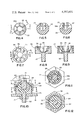
- FIG. 4 is a top view of the rubber ball member illustrated in FIG. 3.
- FIG. 5 is a cross-section of the ball member taken generally along line 5--5 of FIG. 4.
- FIG. 6 is a cross-section of the ball member taken generally along line 6--6 of FIG. 4;
- FIG. 7 is a top view of the lower clamping member illustrated in FIG. 3;
- FIG. 8 is a cross-section of the lower clamping member taken generally along line 8--8 of FIG. 7;
- FIG. 9 is a cross-section of the lower clamping member taken generally along line 9--9 of FIG. 7;
- FIG. 10 is a fragmentary section of the lamp and support unit illustrating the universal support portion
- FIG. 11 is a cross-section taken generally along line 11--11 of FIG. 10;
- FIG. 12 is a cross-section taken generally along line 12--12 of FIG. 10.
- the present rectangular lamp and universal support unit 10 is illustrated and is seen to generally include a rectangular plastic reflector member 11, preferably constructed of an impact resistant plastic, having a highly mirrorized paraboloidal inner surface 12 for reflecting light forwardly from a tungsten-halogen bulb 14.
- the reflector 11 is closed by a generally rectangular lens 15 that may be constructed of either plastic or a vitreous glass.
- the reflector 11 is adjustably supported on vehicle panel 18 by a single point universal support 20 that includes polygonal projection 21 extending centrally downwardly from the reflector 11.
- the universal support 20 permits adjustment of the lamp beam to substantially any position, either vertically or horizontally, without any further adjusting devices, and also provides for a high degree of shock-absorbing.
- the universal support 20 includes the hexagonal post 21 formed integrally with reflector 11 that carries a synthetic rubber ball 22 clamped to the post by a lower annular clamp member 23 and an upper annular clamp member 24 that are threadedly engaged with each other.
- the clamp members 23 and 24 not only fix the lamp beam at the proper attitude, but also serve to clamp the shock absorbing rubber ball 22 to the post 21.
- the rubber shock absorbing ball 22 has a hexagonal closed end bore 26 therein that receives the complementary post 21 on the reflector 11.
- the bore 26 has a peripheral recess 27 that receives a peripheral flange 28 on the post 21 for the purpose of axially locating and locking the post 21 with respect to the ball 22.
- a plurality of slots 28a in the ball 22 extend outwardly from the bore 26 and define a plurality of resilient fingers 29 that grasp the outer surface of the post 21.
- Fingers 29 flex outwardly to permit the insertion of the post 21 therein and as the flange 28 is slid downwardly within the bore 26 it snaps into the bore recess 27 and fingers 29 then return to their relaxed positions.
- the lower clamping member 23 is annular in configuration and has a threaded downwardly extending post 30 that extends through vehicle panel 18, as seen in FIG. 10, and receives a fastener nut 31 for holding the entire lamp unit 10 to the vehicle panel.
- the clamp member 23 has a threaded outer surface 33 that threadedly receives threaded flange 34 on the upper clamping member 24.
- a semi-spherical supporting surface is defined within the lower clamping member 23 by a plurality of radially extending projections 35 integrally molded therein that have arcuate upper surfaces 36 that receive and engage the lower side of the ball member 22, as seen in FIG. 10.
- the upper clamping member 24 has a frusto-spherical inner surface 38 that engages and clamps against the upper side of the ball member 22.
- the outer surface 39 of the upper clamp member 24 is hexagonal in configuration to receive a wrench for tightening the upper clamping member 24 and the lower clamping member 23 against the ball member 22.
- the ball member 22 and the lamp beam may be positioned in almost any desired attitude both vertically and horizontally.
- the upper clamping member is threaded downwardly over the lower clamping member, squeezing the flexible fingers 29 of the ball against the post 21, clamping the ball to the post, and positively preventing either rotational or axial movement of the post with respect to the ball.
- this clamping action positively locks the lamp 10 in its adjusted angular position.
- the ball 22 Since the ball 22 is constructed entirely of a resilient synthetic rubber material, it has an extremely high schock absorbing characteristic and provides adequate support for the lamp unit because the post 21, which is formed integrally with the reflector 11, is of a substantially rigid impact resistant plastic material.
Abstract
Description
Claims (11)
Priority Applications (2)
| Application Number | Priority Date | Filing Date | Title |
|---|---|---|---|
| US06/220,248 US4357651A (en) | 1980-12-23 | 1980-12-23 | Rectangular seal beam lamp and universal support assembly |
| US06/241,395 US4414613A (en) | 1980-12-23 | 1981-03-06 | Rectangular seal beam lamp and support with halogen bulb |
Applications Claiming Priority (1)
| Application Number | Priority Date | Filing Date | Title |
|---|---|---|---|
| US06/220,248 US4357651A (en) | 1980-12-23 | 1980-12-23 | Rectangular seal beam lamp and universal support assembly |
Related Child Applications (1)
| Application Number | Title | Priority Date | Filing Date |
|---|---|---|---|
| US06/241,395 Continuation-In-Part US4414613A (en) | 1980-12-23 | 1981-03-06 | Rectangular seal beam lamp and support with halogen bulb |
Publications (1)
| Publication Number | Publication Date |
|---|---|
| US4357651A true US4357651A (en) | 1982-11-02 |
Family
ID=22822739
Family Applications (1)
| Application Number | Title | Priority Date | Filing Date |
|---|---|---|---|
| US06/220,248 Expired - Fee Related US4357651A (en) | 1980-12-23 | 1980-12-23 | Rectangular seal beam lamp and universal support assembly |
Country Status (1)
| Country | Link |
|---|---|
| US (1) | US4357651A (en) |
Cited By (36)
| Publication number | Priority date | Publication date | Assignee | Title |
|---|---|---|---|---|
| US4509106A (en) * | 1982-06-28 | 1985-04-02 | Stewart-Warner Corporation | Self-housed rectangular lamp assembly with a replaceable halogen bulb lamp unit |
| US5062026A (en) * | 1988-12-16 | 1991-10-29 | Mag Instruments | Flashlight holder clamp assembly |
| US5109321A (en) * | 1988-12-16 | 1992-04-28 | Mag Instrument, Inc. | Flashlight holder clamp assembly |
| US5128841A (en) * | 1988-12-16 | 1992-07-07 | Mag Instrument, Inc. | Flashlight holder clamp assembly |
| US5132492A (en) * | 1991-05-06 | 1992-07-21 | Heath Company | Limited travel universally adjustable electrical fixture |
| US5184884A (en) * | 1988-12-16 | 1993-02-09 | Mag Instruments, Inc. | Flashlight holder clamp assembly |
| US5258899A (en) * | 1992-11-19 | 1993-11-02 | Kent Chen | Motion sensor lighting control |
| US5270911A (en) * | 1988-12-16 | 1993-12-14 | Mag Instrument, Inc. | Flashlight holder clamp assembly |
| US5335159A (en) * | 1992-05-19 | 1994-08-02 | Regent Lighting Corporation | Plastic lamp holder |
| US5510967A (en) * | 1994-12-13 | 1996-04-23 | Osram Sylvania Inc. | Hid headlamp assembly |
| US5515246A (en) * | 1988-12-16 | 1996-05-07 | Mag Instrument, Inc. | Holder clamp assembly |
| US5860728A (en) * | 1993-02-08 | 1999-01-19 | Mag Instrument, Inc. | Holder clamp assembly |
| US6305241B1 (en) * | 1999-06-28 | 2001-10-23 | Shimano, Inc. | Handlebar adapter for mounting a bicycle display |
| US20060120069A1 (en) * | 2004-12-07 | 2006-06-08 | Mag Instrument, Inc. | Circuitry for portable lighting devices and portable rechargeable electronic devices |
| US20060193128A1 (en) * | 2004-12-07 | 2006-08-31 | West Stacey H | Circuitry for portable lighting devices and portable rechargeable electronic devices |
| US20060236651A1 (en) * | 2005-04-04 | 2006-10-26 | Patent-Treuhand-Gesellschaft Fur Elektrische Gluhlampen Mbh | Electric lamp having an outer bulb |
| US7249875B1 (en) | 2005-04-15 | 2007-07-31 | Baja Designs, Inc. | Off-road accessory light rack |
| US20080029635A1 (en) * | 2005-02-16 | 2008-02-07 | Morgan Christopher D | Overmolded inertia sensor mass for a seat belt retractor |
| US20090296379A1 (en) * | 2008-06-02 | 2009-12-03 | Honeywell International | Elevated airport lights with an adjustment mechanism |
| US7695170B1 (en) * | 2007-06-27 | 2010-04-13 | Taymac Corporation | Outdoor swivel head spotlight |
| US20100116121A1 (en) * | 2007-04-27 | 2010-05-13 | Eason Donald H | Percussion Instrument Support Apparatus |
| US20120099333A1 (en) * | 2010-10-25 | 2012-04-26 | Ching-Hsiang Wang | Flashlight Mount |
| US8169165B2 (en) | 2009-01-14 | 2012-05-01 | Mag Instrument, Inc. | Multi-mode portable lighting device |
| US20130077904A1 (en) * | 2011-09-26 | 2013-03-28 | Kenneth Alvin Jungeberg | Friction locking spherical joint |
| USD689502S1 (en) | 2013-01-18 | 2013-09-10 | Swift Distribution, Inc. | Device support apparatus |
| USD748937S1 (en) | 2013-01-22 | 2016-02-09 | Swift Distribution, LLC | Support apparatus |
| USD749344S1 (en) | 2013-01-22 | 2016-02-16 | Swift Distribution, LLC | Support yoke |
| US9279437B2 (en) * | 2011-11-24 | 2016-03-08 | Knorr-Bremse Systeme Fuer Nutzfahrzeuge Gmbh | Adjustable holding device for sensors |
| US9709356B1 (en) * | 2014-05-06 | 2017-07-18 | Tja Design Llc | Multi-axis firearm foregrip |
| US10012261B2 (en) | 2011-09-26 | 2018-07-03 | Kenneth Alvin Jungeberg | Method and apparatus for releasably immobilizing an attachment to an external object |
| US20180254027A1 (en) * | 2017-03-01 | 2018-09-06 | Guitar Center, Inc. | Vibration Isolation Mount |
| US20190234535A1 (en) * | 2018-01-31 | 2019-08-01 | A. Raymond Et Cie. | Ball And Socket Fastener For Attaching Components |
| US11067254B1 (en) | 2019-10-08 | 2021-07-20 | Bestop Baja, Llc | Auxiliary light for mounting to a vehicle |
| US11149943B2 (en) * | 2019-03-29 | 2021-10-19 | Radoslaw K. BUCHOWIECKI | Tool for releasably holding a torch |
| US11248648B2 (en) * | 2019-03-19 | 2022-02-15 | Pegatron Corporation | Rotatable ball joint and universal ball joint assembly |
| US11273751B2 (en) | 2019-10-08 | 2022-03-15 | Bestop Baja, Llc | Auxiliary light for mounting to a vehicle |
Citations (6)
| Publication number | Priority date | Publication date | Assignee | Title |
|---|---|---|---|---|
| US1560458A (en) * | 1921-04-07 | 1925-11-03 | Clymer Mfg Company | Spotlight |
| US2614437A (en) * | 1950-05-10 | 1952-10-21 | Harry E Meggitt | Control means for vehicle mirrors, fog lights, and the like |
| US2854892A (en) * | 1955-09-26 | 1958-10-07 | Frank P Stark | Rear view mirror for tractor and trailer combination type of motor truck |
| US3278203A (en) * | 1964-02-05 | 1966-10-11 | Snyder Mfg Company | Swivel connector for lamps and the like |
| US3501627A (en) * | 1967-12-26 | 1970-03-17 | Gen Electric | Airport lighting fixture |
| US4103323A (en) * | 1976-09-20 | 1978-07-25 | Dominion Auto Accessories Limited | Lamp with resilient retainer ring |
-
1980
- 1980-12-23 US US06/220,248 patent/US4357651A/en not_active Expired - Fee Related
Patent Citations (6)
| Publication number | Priority date | Publication date | Assignee | Title |
|---|---|---|---|---|
| US1560458A (en) * | 1921-04-07 | 1925-11-03 | Clymer Mfg Company | Spotlight |
| US2614437A (en) * | 1950-05-10 | 1952-10-21 | Harry E Meggitt | Control means for vehicle mirrors, fog lights, and the like |
| US2854892A (en) * | 1955-09-26 | 1958-10-07 | Frank P Stark | Rear view mirror for tractor and trailer combination type of motor truck |
| US3278203A (en) * | 1964-02-05 | 1966-10-11 | Snyder Mfg Company | Swivel connector for lamps and the like |
| US3501627A (en) * | 1967-12-26 | 1970-03-17 | Gen Electric | Airport lighting fixture |
| US4103323A (en) * | 1976-09-20 | 1978-07-25 | Dominion Auto Accessories Limited | Lamp with resilient retainer ring |
Cited By (51)
| Publication number | Priority date | Publication date | Assignee | Title |
|---|---|---|---|---|
| US4509106A (en) * | 1982-06-28 | 1985-04-02 | Stewart-Warner Corporation | Self-housed rectangular lamp assembly with a replaceable halogen bulb lamp unit |
| US5515246A (en) * | 1988-12-16 | 1996-05-07 | Mag Instrument, Inc. | Holder clamp assembly |
| US5062026A (en) * | 1988-12-16 | 1991-10-29 | Mag Instruments | Flashlight holder clamp assembly |
| US5109321A (en) * | 1988-12-16 | 1992-04-28 | Mag Instrument, Inc. | Flashlight holder clamp assembly |
| US5128841A (en) * | 1988-12-16 | 1992-07-07 | Mag Instrument, Inc. | Flashlight holder clamp assembly |
| US5184884A (en) * | 1988-12-16 | 1993-02-09 | Mag Instruments, Inc. | Flashlight holder clamp assembly |
| US5667185A (en) * | 1988-12-16 | 1997-09-16 | Mag Instrument, Inc. | Holder clamp assembly |
| US5270911A (en) * | 1988-12-16 | 1993-12-14 | Mag Instrument, Inc. | Flashlight holder clamp assembly |
| US5660363A (en) * | 1988-12-16 | 1997-08-26 | Mag Instrument, Inc. | Holder clamp assembly |
| US5132492A (en) * | 1991-05-06 | 1992-07-21 | Heath Company | Limited travel universally adjustable electrical fixture |
| US5335159A (en) * | 1992-05-19 | 1994-08-02 | Regent Lighting Corporation | Plastic lamp holder |
| US5258899A (en) * | 1992-11-19 | 1993-11-02 | Kent Chen | Motion sensor lighting control |
| US5860728A (en) * | 1993-02-08 | 1999-01-19 | Mag Instrument, Inc. | Holder clamp assembly |
| US5510967A (en) * | 1994-12-13 | 1996-04-23 | Osram Sylvania Inc. | Hid headlamp assembly |
| US6305241B1 (en) * | 1999-06-28 | 2001-10-23 | Shimano, Inc. | Handlebar adapter for mounting a bicycle display |
| US6557437B2 (en) | 1999-06-28 | 2003-05-06 | Shimano, Inc. | Handlebar adapter for mounting a bicycle display |
| US7609005B2 (en) | 2004-12-07 | 2009-10-27 | Mag Instrument, Inc. | Circuitry for portable lighting devices and portable rechargeable electronic devices |
| US20090284170A1 (en) * | 2004-12-07 | 2009-11-19 | Mag Instrument, Inc. | Circuitry for portable lighting devices and portable rechargeable electronic devices |
| US8482209B2 (en) | 2004-12-07 | 2013-07-09 | Mag Instrument, Inc. | Circuitry for portable lighting devices and portable rechargeable electronic devices |
| US20070064354A1 (en) * | 2004-12-07 | 2007-03-22 | Mag Instrument, Inc. | Circuitry for portable lighting devices and portable rechargeable electronic devices |
| US7723921B2 (en) | 2004-12-07 | 2010-05-25 | West Stacey H | Circuitry for portable lighting devices and portable rechargeable electronic devices |
| US20060193128A1 (en) * | 2004-12-07 | 2006-08-31 | West Stacey H | Circuitry for portable lighting devices and portable rechargeable electronic devices |
| US20100013394A1 (en) * | 2004-12-07 | 2010-01-21 | Mag Instrument, Inc. | Ciruitry for portable lighting devices and portable rechargeable electronic devices |
| US7579782B2 (en) | 2004-12-07 | 2009-08-25 | Mag Instrument, Inc. | Circuitry for portable lighting devices and portable rechargeable electronic devices |
| US20060120069A1 (en) * | 2004-12-07 | 2006-06-08 | Mag Instrument, Inc. | Circuitry for portable lighting devices and portable rechargeable electronic devices |
| US20080029635A1 (en) * | 2005-02-16 | 2008-02-07 | Morgan Christopher D | Overmolded inertia sensor mass for a seat belt retractor |
| US7416150B2 (en) * | 2005-02-16 | 2008-08-26 | Key Safety Systems, Inc. | Overmolded inertia sensor mass for a seat belt retractor |
| US20060236651A1 (en) * | 2005-04-04 | 2006-10-26 | Patent-Treuhand-Gesellschaft Fur Elektrische Gluhlampen Mbh | Electric lamp having an outer bulb |
| US7249875B1 (en) | 2005-04-15 | 2007-07-31 | Baja Designs, Inc. | Off-road accessory light rack |
| US20100116121A1 (en) * | 2007-04-27 | 2010-05-13 | Eason Donald H | Percussion Instrument Support Apparatus |
| US8106278B2 (en) * | 2007-04-27 | 2012-01-31 | Swift Distribution Inc. | Percussion instrument support apparatus |
| US7695170B1 (en) * | 2007-06-27 | 2010-04-13 | Taymac Corporation | Outdoor swivel head spotlight |
| US20090296379A1 (en) * | 2008-06-02 | 2009-12-03 | Honeywell International | Elevated airport lights with an adjustment mechanism |
| US8169165B2 (en) | 2009-01-14 | 2012-05-01 | Mag Instrument, Inc. | Multi-mode portable lighting device |
| US9035576B2 (en) | 2009-01-14 | 2015-05-19 | Mag Instrument, Inc. | Multi-mode portable lighting device |
| US20120099333A1 (en) * | 2010-10-25 | 2012-04-26 | Ching-Hsiang Wang | Flashlight Mount |
| US10012261B2 (en) | 2011-09-26 | 2018-07-03 | Kenneth Alvin Jungeberg | Method and apparatus for releasably immobilizing an attachment to an external object |
| US9157471B2 (en) * | 2011-09-26 | 2015-10-13 | Kenneth Alvin Jungeberg | Friction locking spherical joint |
| US20130077904A1 (en) * | 2011-09-26 | 2013-03-28 | Kenneth Alvin Jungeberg | Friction locking spherical joint |
| US9279437B2 (en) * | 2011-11-24 | 2016-03-08 | Knorr-Bremse Systeme Fuer Nutzfahrzeuge Gmbh | Adjustable holding device for sensors |
| USD689502S1 (en) | 2013-01-18 | 2013-09-10 | Swift Distribution, Inc. | Device support apparatus |
| USD748937S1 (en) | 2013-01-22 | 2016-02-09 | Swift Distribution, LLC | Support apparatus |
| USD749344S1 (en) | 2013-01-22 | 2016-02-16 | Swift Distribution, LLC | Support yoke |
| US9709356B1 (en) * | 2014-05-06 | 2017-07-18 | Tja Design Llc | Multi-axis firearm foregrip |
| US10866061B2 (en) | 2014-05-06 | 2020-12-15 | Tja Design Llc | Multi-axis firearm foregrip |
| US20180254027A1 (en) * | 2017-03-01 | 2018-09-06 | Guitar Center, Inc. | Vibration Isolation Mount |
| US20190234535A1 (en) * | 2018-01-31 | 2019-08-01 | A. Raymond Et Cie. | Ball And Socket Fastener For Attaching Components |
| US11248648B2 (en) * | 2019-03-19 | 2022-02-15 | Pegatron Corporation | Rotatable ball joint and universal ball joint assembly |
| US11149943B2 (en) * | 2019-03-29 | 2021-10-19 | Radoslaw K. BUCHOWIECKI | Tool for releasably holding a torch |
| US11067254B1 (en) | 2019-10-08 | 2021-07-20 | Bestop Baja, Llc | Auxiliary light for mounting to a vehicle |
| US11273751B2 (en) | 2019-10-08 | 2022-03-15 | Bestop Baja, Llc | Auxiliary light for mounting to a vehicle |
Similar Documents
| Publication | Publication Date | Title |
|---|---|---|
| US4357651A (en) | Rectangular seal beam lamp and universal support assembly | |
| US2266329A (en) | Head lamp mounting | |
| US5010455A (en) | Headlamp assembly | |
| US4794495A (en) | Headlamp assembly | |
| KR930008687Y1 (en) | Headlight for vehicle | |
| CA1110601A (en) | Shock mounting bracket for lamp bulbs | |
| KR100736471B1 (en) | Headlight lamp | |
| KR930007618Y1 (en) | Head lamp for automobile | |
| US4437145A (en) | Shock absorbing lamp assembly for baseless cartridge bulbs and the like | |
| US2910577A (en) | Vehicle headlamp mounting | |
| US2733335A (en) | Headlamp adjusting device | |
| US4970629A (en) | Headlamp assembly | |
| US2910576A (en) | Vehicle headlamp mounting | |
| US4414613A (en) | Rectangular seal beam lamp and support with halogen bulb | |
| US1472509A (en) | A firm | |
| US2281643A (en) | Head lamp | |
| US4985814A (en) | Warning light with quadruple reflective surfaces | |
| US5126924A (en) | Motor vehicle headlamp | |
| JPH0676033B2 (en) | Adjustable fixing device for automobile headlights | |
| US3949215A (en) | Lamp assembly | |
| US4231081A (en) | Bulb mount for vehicle lamps | |
| US2138076A (en) | Lighting unit mounting | |
| US4764855A (en) | Globe securement means | |
| US3115307A (en) | Automotive vehicle marker lamp | |
| US3558872A (en) | Automotive driving light |
Legal Events
| Date | Code | Title | Description |
|---|---|---|---|
| MAFP | Maintenance fee payment |
Free format text: PAYMENT OF MAINTENANCE FEE, 4TH YEAR, PL 96-517 (ORIGINAL EVENT CODE: M170); ENTITY STATUS OF PATENT OWNER: LARGE ENTITY Year of fee payment: 4 |
|
| FEPP | Fee payment procedure |
Free format text: PAYER NUMBER DE-ASSIGNED (ORIGINAL EVENT CODE: RMPN); ENTITY STATUS OF PATENT OWNER: LARGE ENTITY Free format text: PAYOR NUMBER ASSIGNED (ORIGINAL EVENT CODE: ASPN); ENTITY STATUS OF PATENT OWNER: LARGE ENTITY |
|
| MAFP | Maintenance fee payment |
Free format text: PAYMENT OF MAINTENANCE FEE, 8TH YEAR, PL 96-517 (ORIGINAL EVENT CODE: M171); ENTITY STATUS OF PATENT OWNER: LARGE ENTITY Year of fee payment: 8 |
|
| AS | Assignment |
Owner name: STEWART-WARNER HOBBS CORPORATION, YALE BOULEVARD A Free format text: ASSIGNMENT OF ASSIGNORS INTEREST.;ASSIGNOR:STEWART-WARNER CORPORATION;REEL/FRAME:005550/0046 Effective date: 19901022 |
|
| FEPP | Fee payment procedure |
Free format text: MAINTENANCE FEE REMINDER MAILED (ORIGINAL EVENT CODE: REM.); ENTITY STATUS OF PATENT OWNER: LARGE ENTITY |
|
| LAPS | Lapse for failure to pay maintenance fees | ||
| FP | Lapsed due to failure to pay maintenance fee |
Effective date: 19941102 |
|
| STCH | Information on status: patent discontinuation |
Free format text: PATENT EXPIRED DUE TO NONPAYMENT OF MAINTENANCE FEES UNDER 37 CFR 1.362 |