US4352957A - Speech detector circuit with associated gain control for a tasi system - Google Patents
Speech detector circuit with associated gain control for a tasi system Download PDFInfo
- Publication number
- US4352957A US4352957A US06/237,758 US23775881A US4352957A US 4352957 A US4352957 A US 4352957A US 23775881 A US23775881 A US 23775881A US 4352957 A US4352957 A US 4352957A
- Authority
- US
- United States
- Prior art keywords
- channel
- gain
- speech
- old
- speech level
- Prior art date
- Legal status (The legal status is an assumption and is not a legal conclusion. Google has not performed a legal analysis and makes no representation as to the accuracy of the status listed.)
- Expired - Lifetime
Links
- 238000005070 sampling Methods 0.000 claims description 4
- 230000005540 biological transmission Effects 0.000 description 19
- 239000000872 buffer Substances 0.000 description 12
- 238000001514 detection method Methods 0.000 description 12
- 238000010586 diagram Methods 0.000 description 3
- 230000011664 signaling Effects 0.000 description 3
- 230000003595 spectral effect Effects 0.000 description 3
- 239000003990 capacitor Substances 0.000 description 2
- 230000001934 delay Effects 0.000 description 2
- 230000006870 function Effects 0.000 description 2
- 230000004048 modification Effects 0.000 description 2
- 238000012986 modification Methods 0.000 description 2
- 230000008901 benefit Effects 0.000 description 1
- 230000006872 improvement Effects 0.000 description 1
- 238000012544 monitoring process Methods 0.000 description 1
- 230000004044 response Effects 0.000 description 1
Images


Classifications
-
- H—ELECTRICITY
- H04—ELECTRIC COMMUNICATION TECHNIQUE
- H04J—MULTIPLEX COMMUNICATION
- H04J3/00—Time-division multiplex systems
- H04J3/17—Time-division multiplex systems in which the transmission channel allotted to a first user may be taken away and re-allotted to a second user if the first user becomes inactive, e.g. TASI
- H04J3/175—Speech activity or inactivity detectors
Definitions
- This invention relates to time assignment speech interpolation systems and, more particularly, to a speech detector with associated gain control for such systems.
- TASI time assignment speech interpolation
- n callers are transmitted across, for example n/2 transmission facilities to a remote location. At that location, the n/2 facilities are connected to n output channels.
- TASI systems operate on the assumption, verified as a statistical fact, that at any given time not all callers will wish to talk simultaneously. In fact, as a general rule, callers are actively talking less than half of the time the talker and the listener are interconnected. Accordingly, TASI systems may be defined as switching systems which interconnect talker and listener only when the talker is actively speaking, provided there is a transmission facility available at that time.
- an input channel is connected to a transmission facility only when a speech signal is detected on that channel by a speech detector. It is desirable that such a speech detector have a variable threshold so that speech may be distinguished from noise even when speech characteristics and ambient noise vary.
- each input channel is provided with a level detector which provides a signal proportional to the amplitude of the input signal amplitude on a particular channel at a given time. This signal is then directed to a centralized comparison means where the signal amplitude is compared against a stored threshold for that channel.
- a centralized speech detector circuit which includes a centralized amplitude detector as opposed to the distributed level detectors employed by May. More importantly, in the May approach, speech is determined to be present when the amplitude of the input signal exceeds a stored threshold at a particular time. However, at any one time, only one input channel may be monitored. It would be desirable to monitor all input channels over a period of time in order to provide more accurate speech detection and to do so on a centralized basis. Speech is then determined to be present only when the average input signal power over an extended period of time exceeds a stored threshold.
- each input channel is sampled and the speech signal samples from all channels are directed to a centralized speech detection circuit including a time speed-up memory.
- the signal samples from each input channel are obtained over a period of time and are continuously read into a centralized memory at a particular input rate and subsequently read out of that memory at a faster rate.
- the centralized time speed-up memory contains the entire recent past signal history for each channel.
- the time compressed amplitude history for each channel is compared in a centralized comparison means. Since the signal history is time compressed, a single, centralized comparison means may be utilized on a time shared basis and yet each of the input channels may be monitored over an extended time period.
- speech detection may be further improved by the provision of an automatic gain control circuit responsive to the aforementioned centralized speech detection circuit.
- Speech detection is enhanced on channels carrying the signals of weak talkers by the gain control circuit by increasing the amplitude of signals on those channels in accordance with the time compressed amplitude history for that channel as stored in the memory of the centralized speech detector.
- This arrangement enhances not only the transmission of the speech of weak talkers but also the ability of the centralized speech detector to distinguish that speech as such.
- FIG. 1 is a block diagram of the sending side of a TASI system
- FIGS. 2A-2B are waveforms depicting the operation of the centralized speech detector of the present invention.
- FIG. 3 is a block diagram of the centralized speech detector circuit of the present invention.
- FIG. 4 is a block diagram of an automatic gain control circuit useful with the centralized speech detector of FIG. 3;
- FIG. 5A is a plot of the desired output of the automatic gain control circuit of FIG. 4 versus the input signal applied thereto;
- FIG. 5B is a plot of the binary value of the old speaker level generated by the speech detector circuit of FIG. 3 versus old speaker levels in dBm;
- FIG. 5C is a plot of the gain applied by the gain control circuit of FIG. 4 in adjusting the input signal amplitude to produce the output of FIG. 5A versus the gain index code identifying that gain, which gain index code is determined in accordance with the binary value of the old speaker level.
- FIG. 1 shows input channel 3 connected to transmission facility 16A.
- a fixed delay buffer or memory means 13 is connected between each of the input channels and the switching network 10. Incoming signals are stored in fixed segmented buffer 13 for a time interval during which a symbol from signalling generator 18 is applied to the transmission facility. This symbol from signalling generator 18 identifies the input channel to which each transmission facility has been assigned at a given time. For example, assume transmission facility 16A has been assigned to input channel 3. Signalling generator 18 generates a symbol representing input channel 3. This symbol is applied to the transmission facility 16A before the speech signal, sometimes referred to as a speech burst. The delay provided by fixed buffer 13 thus provides the time interval required to insert the symbol before the speech signal. At the receiving side, the symbol identifying input channel 3 is utilized to route the conversation from input channel 3 to the appropriate party.
- Input signals from the input channels 1 . . . 31 are converted into digital (P.C.M.) form by means of the analog-to-digital converters 28, 30, 32, 34 and others.
- the sampling rate of each of these analog-to-digital converters is 8000 samples per second.
- each sample of an incoming signal represents the amplitude of the signal on each input channel over a 0.000125 second interval.
- These samples are directed to a gain control circuit 90 which will be more fully described below. From the gain control circuit 90, the most recent of these samples are directed to fixed buffer 13 and stored on a per channel basis in identifiable segments 36, 38, 40, 42, and others of that buffer.
- the 256 most recent samples from each input channel are stored in the segment associated with that channel.
- These digital amplitude samples when retrieved from fixed delay buffer 13, may be stored for variable times in variable delay buffers 44, and then transmitted on a facility when a facility becomes available. This is described in the aforementioned Clingenpeel patent.
- the digital samples Prior to transmission, the digital samples are reconstituted to analog by the digital-to-analog converters 46, 48, 50, and others before the signals are applied to the transmission facilities 1A . . . 16A.
- samples stored in the fixed delay buffer 13 in addition to being directed to the switching network 10 are also directed to the centralized speech detector circuit 11.
- samples are retrieved on a channel by channel basis.
- the channel being retrieved at any given time is determined by the count of channel address counter 52 which is driven by a clock means 54.
- the most recent 128 of the 256 samples stored from each channel are delivered to speech detector circuit 11 by the sample address counter 58 which is also driven by clock means 54 before samples from the next channel are retrieved.
- the samples retrieved from fixed buffer 13 are retrieved by the clock means 54 and counters 52 and 58 in a time faster than real time.
- samples are retrieved at a rate of 1024 KHz., or 128 times faster than real time.
- digital samples representing input signal amplitudes over a relatively long period of real time may be retrieved in an interval many times faster than real time.
- every 0.000125 second, 128 samples are retrieved which represent the input signal history for a particular channel which had been accumulated over a 0.016 sec. interval. In this manner, the amplitude history for all channels may be continually monitored with a single centralized speech detector.
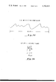
- FIG. 2A depicts an input signal on an input channel, such as channel 1, over a 16 millisecond period of time. This signal is continuously sampled at 125 microsecond intervals and the samples are stored in fixed buffer 13. The samples are read out and reconstituted by digital-to-analog converter 60 into the time compressed signal shown in FIG. 2B.
- FIG. 2B depicts the signal power in the input signal for our channel which occurs over the 0.016 second interval shown in FIG. 2A but compressed in time, e.g., by a factor of 128:1.
- the centralized speech detector of the present invention will be described in detail.
- the time compressed signal from a particular input channel is directed from fixed buffer 13 to a digital-to-analog converter 60, the output of which is exemplified in FIG. 2B described above.
- the output of the digital-to-analog converter 60 is directed to a speech envelope detector shown generally at 61.
- the speech envelope detector comprises a spectral weighting filter 62, a full wave rectifier 64 and an RC circuit comprising a resistor 66 and a capacitor 67.
- the spectral weighting filter smooths and shapes the signal and weights it heavily in the 800-900 Hz. range in which speech normally occurs.
- the output of the spectral weighting filter 62 is rectified and applied to the RC circuit 66, 67, the output of the speech envelope detector 61 being the voltage across capacitor 67.
- the output of the speech envelope detector 61 is a voltage proportional to the average power of the input signal for a particular input channel taken over a 0.016 second interval. This voltage is amplified by an amplifier 68 and applied to a first comparison means 70 for comparing the time compressed input signal for each channel with the variable threshold V th1 for that channel. The purpose of the amplifier 68 is to ensure that the comparison means 70 operates in the proper range.
- the old speaker level for each of the input channels is stored in a speech history storage means 72 which comprises a digital memory containing an 8 bit byte representing the old speaker level for each input channel.
- V th1 is the old threshold for each channel and is merely a value specified by Pad 76 which is K db below the old speaker level. In the preferred embodiment K is 9 db.
- SP is directed from processor 80 to the controller 15 so that switching may be accomplished.
- the speech detector circuit of the present invention also includes a means for setting a new threshold for each channel whenever the average power of the time compressed input signal differs from the old speaker level stored in the speech history memory 72.
- the means for setting a new threshold comprises a servo loop including a second comparison means 78, processor 80 and the aforementioned speech history storage means 72.
- the comparator 78 compares the time compressed input signal with the old speaker level as stored in the speech history memory 72 after that speaker level has been reconstituted to analog form via digital-to-analog converter 74.
- the processor 80 increments the old speaker level stored in the speech history memory 72 to a new and higher level for the next time that an input signal is compared for that channel. If the incoming signal power is below the old speaker level stored in speech history memory 72, the processor 80 reduces the old speaker level to a new and lower threshold for the next time an input signal on that channel is monitored.
- processor 80 Since it is not advantageous to update the old speaker level as stored in speech history memory 72 instantaneously, the processor 80 ensures that the old speaker level for each channel is updated only after a minimum time such as 0.016 second has elapsed. Moreover, in accordance with the preferred embodiment of the present invention, processor 80 permits the updating of the old speaker level stored in memory 72 only when speech is present as determined by the output of the first comparison means 70. In this manner, the variable threshold is only adjusted by a speaker's volume and not by noise.
- the gain control circuit 90 includes a first programmable read only memory (PROM) 91 and a second programmable read only memory (PROM) 93 responsive thereto.
- the gain control circuit 90 further includes a random access memory (RAM) 92 to which gain index codes from PROM 91 are directed and from which the same gain index codes are directed to PROM 93.
- RAM random access memory
- Digital samples of input signals from analog-to-digital converters 28-34 and others on lines 1 to 31 are also directed to PROM 93. The amplitude of these samples is adjusted by PROM 93 in accordance with the function shown in FIG. 5A.
- the gain control circuit 90 applies a varying amount of gain to input signal samples having an amplitude less than a predetermined minimum such as, for example, -24 dBm.
- the gain adjustment to these samples is determined in accordance with a gain index code applied to PROM 93 from RAM 92.
- the gain index code for a particular channel is determined by the binary value of the old speaker level for that channel.
- the binary old speaker level for a given channel is directed to PROM 91 from the speech history storage means 72 of the speech detector 11.
- PROM 91 then generates gain index codes in accordance with the binary old speaker level. From FIG. 5B, it can be seen that when the old speaker level is greater than -24 dBm, the binary old speaker level is greater than 80.
- the gain index code as determined by PROM 91 is zero, and accordingly the gain is zero.
- the old speaker level is less than -24 dBm, a gain index code according to the function shown in FIG. 5C is generated by the PROM 91.
- the gain index code generated by PROM 91 for each channel is stored in RAM 92 and is retrieved under the command of the channel index counter 52 at such time as the gain for that particular channel is to be adjusted. At such time the gain index code is directed to PROM 93.
- the gain index code from RAM 92 is utilized to adjust the gain at PROM 93 in steps ranging from zero to 7.5 dB. Incoming signal sample amplitudes are thus adjusted by varying amounts within this range.
- the gain adjusted digital samples from PROM 93 are then directed to the fixed buffer 13 from which they are subsequently retrieved and directed to the speech detector 11 and also to switching network 10 if speech is detected. Accordingly, it is the gain adjusted digital samples which are utilized in the speech history storage means 72 of the speech detector 11 as a representation of the old speaker level.
Abstract
Description
Claims (8)
Priority Applications (13)
| Application Number | Priority Date | Filing Date | Title |
|---|---|---|---|
| US06/237,758 US4352957A (en) | 1980-03-17 | 1981-03-04 | Speech detector circuit with associated gain control for a tasi system |
| GB8107929A GB2075312B (en) | 1980-03-17 | 1981-03-13 | Speech detector circuit for a tasi system |
| AU68393/81A AU541271B2 (en) | 1980-03-17 | 1981-03-16 | Speech detector circuit for a tasi system |
| NL8101258A NL8101258A (en) | 1980-03-17 | 1981-03-16 | Circuitry for determining whether the input signals of a number of input channels represent speech. |
| FR8105203A FR2482348A1 (en) | 1980-03-17 | 1981-03-16 | SPEECH SENSOR CIRCUIT AND ASSOCIATED GAIN CONTROL FOR A TIME-ALLOCATED SPEECH SIGNAL NESTING SYSTEM |
| BR8101540A BR8101540A (en) | 1980-03-17 | 1981-03-16 | CENTRALIZED CIRCUIT TO DETERMINE IF INPUT SIGNS FROM A PLURALITY OF INPUT CHANNELS ARE SPEAKING SIGNS |
| CA000373071A CA1159971A (en) | 1980-03-17 | 1981-03-16 | Speech detector circuit with associated gain control for a tasi system |
| IT20386/81A IT1137435B (en) | 1980-03-17 | 1981-03-17 | SPEAKER DETECTOR CIRCUIT WITH ASSOCIATED GAIN CONTROL FOR A TASI SYSTEM |
| CH1802/81A CH654962A5 (en) | 1980-03-17 | 1981-03-17 | CENTRAL CIRCUIT DEVICE FOR SPEAKER RECOGNITION FOR A TASI SYSTEM. |
| DE19813110275 DE3110275A1 (en) | 1980-03-17 | 1981-03-17 | VOICE RECOGNITION SWITCHING ARRANGEMENT WITH RELATED AMPLIFIER CONTROL FOR A TASI SYSTEM |
| MX81186402A MX151600A (en) | 1980-03-17 | 1981-03-17 | IMPROVEMENTS IN A SPEAKING DETECTOR CIRCUIT WITH ASSOCIATED GAIN CONTROL FOR A "TASI" SYSTEM |
| SE8101697A SE8101697L (en) | 1980-03-17 | 1981-03-17 | SPEECH DETECTION CIRCUIT WITH CONNECTED AMPLIFYING REGULATION FOR A TASI SYSTEM |
| IL62393A IL62393A (en) | 1980-03-17 | 1981-03-17 | Speech detector circuit for a tasi communication system |
Applications Claiming Priority (2)
| Application Number | Priority Date | Filing Date | Title |
|---|---|---|---|
| US06/131,159 US4365112A (en) | 1980-03-17 | 1980-03-17 | Speech detector circuit for a TASI system |
| US06/237,758 US4352957A (en) | 1980-03-17 | 1981-03-04 | Speech detector circuit with associated gain control for a tasi system |
Related Parent Applications (1)
| Application Number | Title | Priority Date | Filing Date |
|---|---|---|---|
| US06/131,159 Continuation-In-Part US4365112A (en) | 1980-03-17 | 1980-03-17 | Speech detector circuit for a TASI system |
Publications (1)
| Publication Number | Publication Date |
|---|---|
| US4352957A true US4352957A (en) | 1982-10-05 |
Family
ID=26829197
Family Applications (1)
| Application Number | Title | Priority Date | Filing Date |
|---|---|---|---|
| US06/237,758 Expired - Lifetime US4352957A (en) | 1980-03-17 | 1981-03-04 | Speech detector circuit with associated gain control for a tasi system |
Country Status (13)
| Country | Link |
|---|---|
| US (1) | US4352957A (en) |
| AU (1) | AU541271B2 (en) |
| BR (1) | BR8101540A (en) |
| CA (1) | CA1159971A (en) |
| CH (1) | CH654962A5 (en) |
| DE (1) | DE3110275A1 (en) |
| FR (1) | FR2482348A1 (en) |
| GB (1) | GB2075312B (en) |
| IL (1) | IL62393A (en) |
| IT (1) | IT1137435B (en) |
| MX (1) | MX151600A (en) |
| NL (1) | NL8101258A (en) |
| SE (1) | SE8101697L (en) |
Cited By (5)
| Publication number | Priority date | Publication date | Assignee | Title |
|---|---|---|---|---|
| US5016247A (en) * | 1989-08-07 | 1991-05-14 | Ibm Corporation | Multihop time assigned speech interpolation (TASI) system for telecommunication networks |
| US5117453A (en) * | 1989-03-02 | 1992-05-26 | Eci Telecom Ltd. | Telecommunication system |
| US5812969A (en) * | 1995-04-06 | 1998-09-22 | Adaptec, Inc. | Process for balancing the loudness of digitally sampled audio waveforms |
| US5836992A (en) * | 1994-10-04 | 1998-11-17 | Medtronic, Inc. | Filtered feedthrough assembly for implantable medical device |
| US9024283B2 (en) | 2010-06-22 | 2015-05-05 | Micron Technology, Inc. | Horizontally oriented and vertically stacked memory cells |
Families Citing this family (2)
| Publication number | Priority date | Publication date | Assignee | Title |
|---|---|---|---|---|
| GB8613327D0 (en) * | 1986-06-02 | 1986-07-09 | British Telecomm | Speech processor |
| US5465317A (en) * | 1993-05-18 | 1995-11-07 | International Business Machines Corporation | Speech recognition system with improved rejection of words and sounds not in the system vocabulary |
Citations (14)
| Publication number | Priority date | Publication date | Assignee | Title |
|---|---|---|---|---|
| US3504352A (en) * | 1968-05-24 | 1970-03-31 | Sanders Associates Inc | Time compression system |
| US3520999A (en) * | 1967-03-27 | 1970-07-21 | Bell Telephone Labor Inc | Digital speech detection system |
| US3649766A (en) * | 1969-12-01 | 1972-03-14 | Bell Telephone Labor Inc | Digital speech detection system |
| US3706091A (en) * | 1970-09-02 | 1972-12-12 | Bell Telephone Labor Inc | Digital threshold detector |
| US3801747A (en) * | 1971-10-19 | 1974-04-02 | J Queffeulou | Speech detector for pcm-tasi system |
| US3832493A (en) * | 1973-06-18 | 1974-08-27 | Itt | Digital speech detector |
| US3832491A (en) * | 1973-02-13 | 1974-08-27 | Communications Satellite Corp | Digital voice switch with an adaptive digitally-controlled threshold |
| US3882458A (en) * | 1974-03-27 | 1975-05-06 | Gen Electric | Voice operated switch including apparatus for establishing a variable threshold noise level |
| US3936611A (en) * | 1974-09-04 | 1976-02-03 | Gte Sylvania Incorporated | Time compression scanner |
| US4028496A (en) * | 1976-08-17 | 1977-06-07 | Bell Telephone Laboratories, Incorporated | Digital speech detector |
| US4052568A (en) * | 1976-04-23 | 1977-10-04 | Communications Satellite Corporation | Digital voice switch |
| US4301333A (en) * | 1977-09-30 | 1981-11-17 | Mcdonnell Douglas Corporation | Speech compression |
| US4303803A (en) * | 1978-08-31 | 1981-12-01 | Kokusai Denshin Denwa Co., Ltd. | Digital speech interpolation system |
| US4314100A (en) * | 1980-01-24 | 1982-02-02 | Storage Technology Corporation | Data detection circuit for a TASI system |
Family Cites Families (1)
| Publication number | Priority date | Publication date | Assignee | Title |
|---|---|---|---|---|
| US4008375A (en) * | 1975-08-21 | 1977-02-15 | Communications Satellite Corporation (Comsat) | Digital voice switch for single or multiple channel applications |
-
1981
- 1981-03-04 US US06/237,758 patent/US4352957A/en not_active Expired - Lifetime
- 1981-03-13 GB GB8107929A patent/GB2075312B/en not_active Expired
- 1981-03-16 FR FR8105203A patent/FR2482348A1/en active Granted
- 1981-03-16 BR BR8101540A patent/BR8101540A/en unknown
- 1981-03-16 AU AU68393/81A patent/AU541271B2/en not_active Ceased
- 1981-03-16 CA CA000373071A patent/CA1159971A/en not_active Expired
- 1981-03-16 NL NL8101258A patent/NL8101258A/en not_active Application Discontinuation
- 1981-03-17 SE SE8101697A patent/SE8101697L/en not_active Application Discontinuation
- 1981-03-17 MX MX81186402A patent/MX151600A/en unknown
- 1981-03-17 IL IL62393A patent/IL62393A/en unknown
- 1981-03-17 DE DE19813110275 patent/DE3110275A1/en not_active Withdrawn
- 1981-03-17 CH CH1802/81A patent/CH654962A5/en not_active IP Right Cessation
- 1981-03-17 IT IT20386/81A patent/IT1137435B/en active
Patent Citations (14)
| Publication number | Priority date | Publication date | Assignee | Title |
|---|---|---|---|---|
| US3520999A (en) * | 1967-03-27 | 1970-07-21 | Bell Telephone Labor Inc | Digital speech detection system |
| US3504352A (en) * | 1968-05-24 | 1970-03-31 | Sanders Associates Inc | Time compression system |
| US3649766A (en) * | 1969-12-01 | 1972-03-14 | Bell Telephone Labor Inc | Digital speech detection system |
| US3706091A (en) * | 1970-09-02 | 1972-12-12 | Bell Telephone Labor Inc | Digital threshold detector |
| US3801747A (en) * | 1971-10-19 | 1974-04-02 | J Queffeulou | Speech detector for pcm-tasi system |
| US3832491A (en) * | 1973-02-13 | 1974-08-27 | Communications Satellite Corp | Digital voice switch with an adaptive digitally-controlled threshold |
| US3832493A (en) * | 1973-06-18 | 1974-08-27 | Itt | Digital speech detector |
| US3882458A (en) * | 1974-03-27 | 1975-05-06 | Gen Electric | Voice operated switch including apparatus for establishing a variable threshold noise level |
| US3936611A (en) * | 1974-09-04 | 1976-02-03 | Gte Sylvania Incorporated | Time compression scanner |
| US4052568A (en) * | 1976-04-23 | 1977-10-04 | Communications Satellite Corporation | Digital voice switch |
| US4028496A (en) * | 1976-08-17 | 1977-06-07 | Bell Telephone Laboratories, Incorporated | Digital speech detector |
| US4301333A (en) * | 1977-09-30 | 1981-11-17 | Mcdonnell Douglas Corporation | Speech compression |
| US4303803A (en) * | 1978-08-31 | 1981-12-01 | Kokusai Denshin Denwa Co., Ltd. | Digital speech interpolation system |
| US4314100A (en) * | 1980-01-24 | 1982-02-02 | Storage Technology Corporation | Data detection circuit for a TASI system |
Cited By (7)
| Publication number | Priority date | Publication date | Assignee | Title |
|---|---|---|---|---|
| US5117453A (en) * | 1989-03-02 | 1992-05-26 | Eci Telecom Ltd. | Telecommunication system |
| US5016247A (en) * | 1989-08-07 | 1991-05-14 | Ibm Corporation | Multihop time assigned speech interpolation (TASI) system for telecommunication networks |
| US5836992A (en) * | 1994-10-04 | 1998-11-17 | Medtronic, Inc. | Filtered feedthrough assembly for implantable medical device |
| US5812969A (en) * | 1995-04-06 | 1998-09-22 | Adaptec, Inc. | Process for balancing the loudness of digitally sampled audio waveforms |
| US9024283B2 (en) | 2010-06-22 | 2015-05-05 | Micron Technology, Inc. | Horizontally oriented and vertically stacked memory cells |
| US9349949B2 (en) | 2010-06-22 | 2016-05-24 | Micron Technology, Inc. | Horizontally oriented and vertically stacked memory cells |
| US9627442B2 (en) | 2010-06-22 | 2017-04-18 | Micron Technology, Inc. | Horizontally oriented and vertically stacked memory cells |
Also Published As
| Publication number | Publication date |
|---|---|
| FR2482348A1 (en) | 1981-11-13 |
| GB2075312B (en) | 1984-06-13 |
| CA1159971A (en) | 1984-01-03 |
| IL62393A0 (en) | 1981-05-20 |
| IT1137435B (en) | 1986-09-10 |
| NL8101258A (en) | 1981-10-16 |
| CH654962A5 (en) | 1986-03-14 |
| DE3110275A1 (en) | 1982-05-19 |
| FR2482348B1 (en) | 1984-12-28 |
| MX151600A (en) | 1985-01-04 |
| IT8120386A0 (en) | 1981-03-17 |
| SE8101697L (en) | 1981-09-18 |
| AU541271B2 (en) | 1985-01-03 |
| IL62393A (en) | 1984-03-30 |
| GB2075312A (en) | 1981-11-11 |
| BR8101540A (en) | 1981-09-22 |
| AU6839381A (en) | 1981-09-24 |
Similar Documents
| Publication | Publication Date | Title |
|---|---|---|
| US4028496A (en) | Digital speech detector | |
| US4449238A (en) | Voice-actuated switching system | |
| US4277645A (en) | Multiple variable threshold speech detector | |
| US5561737A (en) | Voice actuated switching system | |
| EP1086453B1 (en) | Noise suppression using external voice activity detection | |
| US4897832A (en) | Digital speech interpolation system and speech detector | |
| US4365112A (en) | Speech detector circuit for a TASI system | |
| US5075687A (en) | Echo suppression with both digital and analog variable attenuators | |
| US4571461A (en) | Conference telephone apparatus | |
| EP0218870B1 (en) | Automatic gain control in a digital signal processor | |
| AU596333B2 (en) | Technique for improved subjective performance in a communication system using attenuated noise-fill | |
| CA1210541A (en) | Conferencing system adaptive signal conditioner | |
| US4352957A (en) | Speech detector circuit with associated gain control for a tasi system | |
| EP0478125B1 (en) | Discriminating information from noise in a communication signal | |
| US4314100A (en) | Data detection circuit for a TASI system | |
| US4382164A (en) | Signal stretcher for envelope generator | |
| US4607362A (en) | Method of and circuit arrangement for establishing conference connections in a switching system | |
| US5436933A (en) | Idle channel noise reduction in a line card having a DSP equalizer | |
| US3050584A (en) | Conference telephone apparatus | |
| US4213014A (en) | Half echo-suppressor for a four-wire telephone line | |
| US4251881A (en) | Centralized automatic gain control circuit | |
| US4564939A (en) | Handsfree telephone | |
| US5021783A (en) | Method for operating an apparatus for facilitating communications | |
| US6590974B1 (en) | Howling controller | |
| JP2962343B2 (en) | Conference call system with audio signal level control function |
Legal Events
| Date | Code | Title | Description |
|---|---|---|---|
| AS | Assignment |
Owner name: STORAGE TECHNOLOGY CORPORATION, A CORP. OF DE. Free format text: ASSIGNMENT OF ASSIGNORS INTEREST.;ASSIGNOR:RUETHER PETER G.;REEL/FRAME:003868/0144 Effective date: 19810324 |
|
| STCF | Information on status: patent grant |
Free format text: PATENTED CASE |
|
| AS | Assignment |
Owner name: COMTECH COMMUNICATIONS CORP., 3400 INDUSTRIAL LANE Free format text: ASSIGNMENT OF ASSIGNORS INTEREST.;ASSIGNOR:STORAGE TECHNOLOGY CORPORATION A DE CORP.;REEL/FRAME:004152/0915 Effective date: 19830701 |
|
| AS | Assignment |
Owner name: REPUBLIC TELCOM SYSTEMS CORPORATION Free format text: CHANGE OF NAME;ASSIGNOR:COMTECH COMMUNICATIONS CORP.;REEL/FRAME:004499/0177 Effective date: 19850122 |
|
| MAFP | Maintenance fee payment |
Free format text: PAYMENT OF MAINTENANCE FEE, 4TH YEAR, PL 96-517 (ORIGINAL EVENT CODE: M170); ENTITY STATUS OF PATENT OWNER: LARGE ENTITY Year of fee payment: 4 |
|
| AS | Assignment |
Owner name: COMTECH COMMUNICATIONS CORP., 3400 INDUSTRIAL LANE Free format text: ASSIGNMENT OF ASSIGNORS INTEREST. SUBJECT TO LICENSE RECITED;ASSIGNOR:STORAGE TECHNOLOGY CORPORATION, A CORP. OF DE.;REEL/FRAME:004556/0127 Effective date: 19830701 Owner name: COMTECH COMMUNICATIONS CORP.,COLORADO Free format text: ASSIGNMENT OF ASSIGNORS INTEREST;ASSIGNOR:STORAGE TECHNOLOGY CORPORATION, A CORP. OF DE.;REEL/FRAME:004556/0127 Effective date: 19830701 |
|
| AS | Assignment |
Owner name: EDELSON TECHNOLOGY, PARTNERS, PARK 80 WEST PLAZA 2 Free format text: ASSIGNMENT OF ASSIGNORS INTEREST;ASSIGNOR:REPUBLIC TELCOM SYSTEMS CORPORATION, A CORP OF DE.;REEL/FRAME:004578/0916 Effective date: 19860516 Owner name: PARSNIP RIVER COMPANY, 4422 I.D.S. CENTER, MINNEAP Free format text: ASSIGNMENT OF ASSIGNORS INTEREST;ASSIGNOR:REPUBLIC TELCOM SYSTEMS CORPORATION, A CORP OF DE.;REEL/FRAME:004578/0916 Effective date: 19860516 Owner name: REYNOLDS CREEK LIMITED, PARTNERSHIP, 1110 MIDWEST Free format text: ASSIGNMENT OF ASSIGNORS INTEREST;ASSIGNOR:REPUBLIC TELCOM SYSTEMS CORPORATION, A CORP OF DE.;REEL/FRAME:004578/0916 Effective date: 19860516 Owner name: CHERRY TREET VENTURES I, 640 NORTHLAND EXECUTIVE C Free format text: ASSIGNMENT OF ASSIGNORS INTEREST;ASSIGNOR:REPUBLIC TELCOM SYSTEMS CORPORATION, A CORP OF DE.;REEL/FRAME:004578/0916 Effective date: 19860516 Owner name: CHERRY TREE VENTURES II, 640 NORTHLAND EXECUTIVE C Free format text: ASSIGNMENT OF ASSIGNORS INTEREST;ASSIGNOR:REPUBLIC TELCOM SYSTEMS CORPORATION, A CORP OF DE.;REEL/FRAME:004578/0916 Effective date: 19860516 |
|
| AS | Assignment |
Owner name: COLORADO NATIONAL BANK OF DENVER THE, Free format text: SECURITY INTEREST;ASSIGNOR:REPUBLIC TELCOM SYSTEMS CORPORATION, A CORP OF DE.;REEL/FRAME:004595/0565 Effective date: 19860812 |
|
| FEPP | Fee payment procedure |
Free format text: MAINTENANCE FEE REMINDER MAILED (ORIGINAL EVENT CODE: REM.); ENTITY STATUS OF PATENT OWNER: LARGE ENTITY |
|
| FEPP | Fee payment procedure |
Free format text: SURCHARGE FOR LATE PAYMENT, PL 96-517 (ORIGINAL EVENT CODE: M176); ENTITY STATUS OF PATENT OWNER: LARGE ENTITY |
|
| MAFP | Maintenance fee payment |
Free format text: PAYMENT OF MAINTENANCE FEE, 8TH YEAR, PL 96-517 (ORIGINAL EVENT CODE: M171); ENTITY STATUS OF PATENT OWNER: LARGE ENTITY Year of fee payment: 8 |
|
| FEPP | Fee payment procedure |
Free format text: PAYOR NUMBER ASSIGNED (ORIGINAL EVENT CODE: ASPN); ENTITY STATUS OF PATENT OWNER: LARGE ENTITY |
|
| AS | Assignment |
Owner name: NORWEST BANK MINNESOTA, NATIONAL ASSOCIATION A NAT Free format text: SECURITY INTEREST;ASSIGNOR:REPUBLIC TELCOM SYSTEMS CORPORATION, A CORP. OF DE;REEL/FRAME:005646/0070 Effective date: 19910211 |
|
| AS | Assignment |
Owner name: REPUBLIC TELCOM SYSTEMS CORPORATION A DE CORPOR Free format text: ASSIGNMENT OF ASSIGNORS INTEREST.;ASSIGNOR:NORWEST BANK MINNESOTA, NATIONAL ASSOCIATION;REEL/FRAME:005967/0396 Effective date: 19911203 |
|
| MAFP | Maintenance fee payment |
Free format text: PAYMENT OF MAINTENANCE FEE, 12TH YEAR, LARGE ENTITY (ORIGINAL EVENT CODE: M185); ENTITY STATUS OF PATENT OWNER: LARGE ENTITY Year of fee payment: 12 |