US4330272A - Means for attaching a headgear to a positioner - Google Patents
Means for attaching a headgear to a positioner Download PDFInfo
- Publication number
- US4330272A US4330272A US06/127,051 US12705180A US4330272A US 4330272 A US4330272 A US 4330272A US 12705180 A US12705180 A US 12705180A US 4330272 A US4330272 A US 4330272A
- Authority
- US
- United States
- Prior art keywords
- headgear
- positioner
- tooth positioner
- cervical
- tooth
- Prior art date
- Legal status (The legal status is an assumption and is not a legal conclusion. Google has not performed a legal analysis and makes no representation as to the accuracy of the status listed.)
- Expired - Lifetime
Links
Images

Classifications
-
- A—HUMAN NECESSITIES
- A61—MEDICAL OR VETERINARY SCIENCE; HYGIENE
- A61C—DENTISTRY; APPARATUS OR METHODS FOR ORAL OR DENTAL HYGIENE
- A61C7/00—Orthodontics, i.e. obtaining or maintaining the desired position of teeth, e.g. by straightening, evening, regulating, separating, or by correcting malocclusions
- A61C7/08—Mouthpiece-type retainers or positioners, e.g. for both the lower and upper arch
-
- A—HUMAN NECESSITIES
- A61—MEDICAL OR VETERINARY SCIENCE; HYGIENE
- A61C—DENTISTRY; APPARATUS OR METHODS FOR ORAL OR DENTAL HYGIENE
- A61C7/00—Orthodontics, i.e. obtaining or maintaining the desired position of teeth, e.g. by straightening, evening, regulating, separating, or by correcting malocclusions
- A61C7/06—Extra-oral force transmitting means, i.e. means worn externally of the mouth and placing a member in the mouth under tension
Definitions
- the present invention relates to an orthodontic appliance, and more particularly to a means for attaching a headgear device to a tooth positioner, preformed or custom made.
- These positioning devices are adapted to be worn between the teeth of the upper and lower jaw, and are activated through the activity of masticatory, lingual, labial, and buccal muscles. Their correcting action depends to a great extent upon an accurate fit or engagement with the teeth. Prior to the preformed positioners, it was necessary to take accurate impressions of the patient's teeth and adjacent soft tissues, and to carefully fashion the appliance to fit the individual patient.
- the headgear dental appliance was developed in part to avoid the fitting problems associated with these custom-made bands.
- These devices consisted of a mouthpiece formed of a resilient material having a curvature substantially conforming to the maxillary dental arch of a normal person. At the front, labial portion of the arch, either wires or a molded portion of the device would project from the arch, and out of the patient's mouth.
- wire When wire was utilized, the wire would be molded into the entire arch and become an integral part thereof. Where the projections were made from the resilient material, wires would be attached to them outside of the mouth. In either case, the wires arched rearwardly outside of the mouth, projecting out and curving around both sides of the face, to the attachment with an elastic band. This band was stretched around the back of the head or neck and connected both ends of the wire. The stretching force was transmitted to the wires, together creating a rearward force which was applied to the teeth.
- U.S. Pat. Nos. 2,822,612; 2,880,509, and 2,983,046 may be seen in this regard.
- the present invention has, as an objective, providing a practical combination of the custom or preformed positioners with cervical or high pull headgear apparatus.
- the positioners may also be used by themselves as a separate treatment or, perhaps more commonly, the headgear temporarily used to supplement or augment the positioner treatment, a simple yet effective way of combining the two treatments which readily permits a subsequent separation is desired.
- One method is to provide a pair of tubes having a diameter sufficient to receive the headgear wires. These tubes have portions which are selectively inserted into the desired position(s) on the positioner during the molding thereof or even after the molding has been completed by the use of an adhesive cement or by heating the wire and inserting it into the positioner.
- a multitude of forms, a hook for example can be attached to the positioner instead of the tubes.
- the headgear portion is provided with two ends for direct insertion into the positioner. These ends, parallel or non-parallel may be inserted directly into existing breathing holes, typically located in the front-labial portion, or they may be inserted into drilled holes which may be selectively drilled at the desired locations. Location on the side of the positioner would enable the headgear to assist with posterior movement of the entire dentition through its action against the positioner appliance.
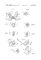
- FIG. 1 is a perspective view showing a headgear portion in use on a patient
- FIG. 2 is a plan view showing an embodiment of the combination headgear positioner
- FIG. 3 is a side sectional view in elevation taken along line III--III of FIG. 2;
- FIG. 4 is a perspective view showing an embodiment of the combination
- FIG. 5 is a perspective view showing an alternate embodiment of the combination in its totality
- FIG. 6 is a perspective view showing an alternate use for an embodiment of the invention.
- FIG. 7 is a plan view with portions cut away showing an embodiment of the invention.
- FIG. 8 is an elevational view in section taken along line VIII--VIII of FIG. 7;
- FIG. 9 is a partial plan view in section showing an anchoring device of the present invention.
- FIG. 10 is a side elevational view taken along line X--X of FIG. 9;
- FIG. 11 is a view similar to FIG. 9 showing an alternate anchoring device
- FIG. 12 is a side elevational view taken along line XII--XII of FIG. 11;
- FIG. 13 is a partial side elevational view showing an alternate anchoring device
- FIG. 14 is a partial side, sectional view in elevation taken along line XIV--XIV of FIG. 13;
- FIG. 15 is a view similar to FIG. 13 showing an alternate anchoring device.
- FIG. 16 is a side perspective view showing an alternate headgear portion in use on a patient.
- FIG. 1 shows an orthodontic patient with the headgear positioner combination in situ. As the positioner portion is inserted in the mouth during use, the only visible portions are parts of the headgear. Wires 1, 2 emerge from a patient's oral cavity and are bent rearwardly, each along one side of the face. The wires 1, 2 are connected to an elastic band 3, which is stretched across the cervix. The stretched band 3 pulls on both wires 1, 2 causing a force to be transmitted to the positioner.
- FIG. 16 An alternative to the cervical headgear shown in FIG. 1 is the high pull headgear shown in FIG. 16.
- a pair of elastic bands 3A and 3B are provided and joined at junction 3C.
- the elastic bands 3A and 3B fit over the top and back portion of a patient's head forming an angle ⁇ therebetween.
- Angle ⁇ typically lies within the range of 10° to 170°.
- the bands 3A and 3B are connected to wire 1A at the junction 3C so that such force will be delivered to the positioner portion.
- the wires 1A, 1A of this form of the invention are at an angle ⁇ to the occlusal plane of the teeth. Angle ⁇ is preferably 28°.
- the stretched bands 3A and 3B pull on wires 1A, 1A to cause both a rearward and upward force to be transmitted to the positioner.
- FIGS. 2-4 One way of attaching the headgear portion to the positioner is illustrated in FIGS. 2-4.
- Attaching wire 6 is connected at 5 to a headgear wire 7.
- the wire 7 has end loops 9 for attachment to an elastic band 12 (FIG. 5).
- a positioner 14 of the type having a plurality of tooth impressions 15 is provided.
- the positioner 14 may be a custom-fitted positioner which is constructed after taking impressions of a particular patient.
- positioner 14 could also be a preformed positioner, such as the type disclosed in my U.S. Pat. No. 3,898,736.
- positioner 14 could alternatively be an eruption guidance appliance of the type disclosed in my U.S. Pat. No.
- the positioner 14 in one embodiment of my invention, is connected to the headgear by the insertion of the attaching wire 6 into holes 26, 27, 28, which are typically provided in the positioner 14 to permit the patient to breathe through the mouth while the positioner 14 is in place.
- Attaching wire 6 is typically U-shaped, and thus forms two prongs 6A, 6B.
- the prongs 6A, 6B may be inserted into the breathing holes 26, 28 as in FIGS. 2 and 3 or, in an alternate embodiment, into separately formed holes 32, 33 (FIG. 4).
- a pair of holes 32, 33 may be formed during the molding of the positioner 14A, or they may be subsequently drilled therein.
- holes 32, 33 permits the selection of various positions posterior of the breathing holes 26, 27, 28, which are usually placed in the anterior portion of the positioner 14. By such posterior placement, the headgear would be able to help with the posterior movement of the whole dentition by its action against the positioner appliance.
- the attachment wires 6 are connected to the outer wire 7 at the connection 5 anterior to the positioner 14 or 14A thereby permitting the outer wire 7 to project from the connection 5 and through the lips 21, 22.
- the outer wire can be formed into different designs--having various loops and curvatures (see, for example, wire 8 in FIG. 4), the selection depending upon the treatment of the teeth desired.
- the different designs are located in close proximity to the mouth, and thereafter, the outer wires uniformly curve rearwardly along the face and towards the back of the head.
- a pair of loops 10, 11 are provided for the connection to the headgear wires 41, 42, which are in turn connected to an elastic band 12 (see FIGS. 4 and 5).
- FIGS. 5 and 7 illustrate an alternate way of attaching a headgear to a positioner.
- FIG. 5 shows the entire headgear-positioner apparatus, with a pair of tubes 51, 52 used to attach the headgear 53 to the positioner 54.
- the tubes 51, 52 are preferably made of stainless steel, a material which is relatively inert while in the mouth.
- the tubes 51, 52 may be of variable length and diameter, with a preferable size being 2-4 mm in length with an opening of 0.045 inch (1.14 mm). As shown in FIG. 7, the tubes 51, 52 can be placed at different lateral locations on the positioner.
- a plurality of cylindrical segments or tubes 55, 57, 59 and a corresponding plurality of symmetrical counterpart tubes 61, 63, 65 demonstrate posteriorly varying positions on a tooth positioner 67.
- a pair of wires 69, 70 is received by the tubes 55 and 61 (as shown), with the therapeutic effect varying as the location of the tubes 55-65 change.
- FIGS. 8-12 show these tubes 51, 52, and 55-65 in greater detail.
- the tubes 51 and 52 are of variable diameter, such that the wire 48 attaching the headgear 53 to the positioner 54 may be safely received therein. A diameter of 0.045 inch proves compatible with most headgear apparatus.
- Each tube 51 and 52 is attached (soldered or welded) to a metal retention portion (not shown) which is inserted as at 154 and 254.
- the positioner is made out of a semi-resilient plastic or rubber material, and may be custom-fitted or selected from a set of preformed positioners, such as those disclosed in my U.S. Pat. No. 3,898,736.
- the metal retention portion 72 of the tube 59 is provided with a pair of holes 72A, 72B.
- the metal retention portion (not shown in FIG. 5) may advantageously consist of a member of bent or flattened pieces.
- the tube 76 is connected to a flat metal retention portion 77 having a pair of holes 78, 79.
- the metal retention portion 77 consists of a pair of angled flat pieces 77A and 77B, each having two holes 78 and 79.
- FIGS. 11 and 12 have a metal portion 81 consisting of two "L"-shaped pieces 83, 85, which form an inner surface 84 parallel to the outer surface 86.
- the tubes 51 and 52 can be used to provide a different type of treatment for the dental arch.
- the tubes 88 and 89 are used in conjunction with an arch-wire 91.
- arch expansion or constriction may be obtained as its force is exerted on the teeth through the positioner appliance 93. In FIG. 6, this force is indicated by arrows A and B.
- Arch-wires can also be attached using a device other than tubes.
- an embedded, bent wire is used to retain an arch-wire.
- an arch-wire 101 is retained by embedded wire 105.
- the embedded wire may also be bent in other shapes, such as that shown by wire 106 in FIG. 15.
- the embedded portions of the wires 105 and 106 are given sufficient bends a, b, c, d, and e, to form an anchor which resists twisting in each direction besides being resistant towards being dislodged.
- the embedded wires 105 and 106 can also be used in conjunction with a high pull retainer. As shown in FIG. 15, a wire 48A, which is connected to the high pull headgear wire 1A, is provided with a loop 107 which engages with a hook 108 formed by the embedded wire 106. The upward force provided by the high pull headgear may thus be transferred to the positioner.
- a regular pull headgear is designed wherein the headgear wire 7 (FIG. 2), is horizontal, i.e., parallel to the occlusal plane of the teeth, when in use by a patient.
- a high pull headgear appliance where the headgear wire 7 makes an angle ⁇ with the occusal plane. This angle ⁇ is preferably 28°.
- both the regular pull and high pull embodiments are provided in a small and regular size.
- the prongs 6A, 6B have a length of 9 mm and form an angle ⁇ of preferably 70°.
- the regular size has prongs 6A, 6B of 12 mm and an angle ⁇ of 46°. (See FIGS. 2 and 4).
Abstract
An orthodontic appliance having a cervical or high pull headgear apparatus attached to a tooth positioner is provided. The positioner, either preformed or custom made and the headgear portion are provided with a secure, yet detachable connection to allow the headgear to be used as a temporary supplement to the tooth positioner and thus provide therapeutic flexibility. Accordingly, the headgear portion may be attached by having wires received in tubes or by hooks, both of which are attached to the outside of the tooth positioner, or by inserting the wires into holes provided in the positioner. The headgear apparatus may thereby be utilized in a number of patients without the requirement for extensive individualized fittings.
Description
1. Field of the Invention
The present invention relates to an orthodontic appliance, and more particularly to a means for attaching a headgear device to a tooth positioner, preformed or custom made.
2. Description of the Prior Art
In order to obtain movement of the teeth to effect an orthodontic treatment, it is necessary to allow a force to be applied to the teeth. Typically, bands on the individual teeth in conjunction with arch-wires have been used. However, this treatment requires the expenditure of a great deal of the practitioner's time and labor in addition to the disadvantages of having the apparatus firmly affixed in the patient's mouth for an extended period of time. Thus, there has been an increasing interest in the use of tooth positioner's both custom-made and preformed devices, (see my U.S. Pat. No. 3,898,736 regarding such preformed devices).
These positioning devices are adapted to be worn between the teeth of the upper and lower jaw, and are activated through the activity of masticatory, lingual, labial, and buccal muscles. Their correcting action depends to a great extent upon an accurate fit or engagement with the teeth. Prior to the preformed positioners, it was necessary to take accurate impressions of the patient's teeth and adjacent soft tissues, and to carefully fashion the appliance to fit the individual patient.
The headgear dental appliance was developed in part to avoid the fitting problems associated with these custom-made bands. These devices consisted of a mouthpiece formed of a resilient material having a curvature substantially conforming to the maxillary dental arch of a normal person. At the front, labial portion of the arch, either wires or a molded portion of the device would project from the arch, and out of the patient's mouth.
When wire was utilized, the wire would be molded into the entire arch and become an integral part thereof. Where the projections were made from the resilient material, wires would be attached to them outside of the mouth. In either case, the wires arched rearwardly outside of the mouth, projecting out and curving around both sides of the face, to the attachment with an elastic band. This band was stretched around the back of the head or neck and connected both ends of the wire. The stretching force was transmitted to the wires, together creating a rearward force which was applied to the teeth. U.S. Pat. Nos. 2,822,612; 2,880,509, and 2,983,046 may be seen in this regard.
However, dentitions of individuals vary greatly among the population. This readily recognizable fact has resulted in a limitation to the extent of treatment available when utilizing the known devices. The mouthpiece portions were not designed to fit the teeth but only match the approximate shape of the arch. Additionally, the known devices are structurally formed into a unit, and are not practically separable--either structurally or therapeutically.
The present invention has, as an objective, providing a practical combination of the custom or preformed positioners with cervical or high pull headgear apparatus. As the positioners may also be used by themselves as a separate treatment or, perhaps more commonly, the headgear temporarily used to supplement or augment the positioner treatment, a simple yet effective way of combining the two treatments which readily permits a subsequent separation is desired.
These objectives are obtained by providing a number of alternative methods of attaching the wire portion of the headgear to the positioner. One method is to provide a pair of tubes having a diameter sufficient to receive the headgear wires. These tubes have portions which are selectively inserted into the desired position(s) on the positioner during the molding thereof or even after the molding has been completed by the use of an adhesive cement or by heating the wire and inserting it into the positioner. Depending upon the method of coupling the headgear with the positioner, a multitude of forms, a hook for example, can be attached to the positioner instead of the tubes.
In an alternate embodiment for the attachment, the headgear portion is provided with two ends for direct insertion into the positioner. These ends, parallel or non-parallel may be inserted directly into existing breathing holes, typically located in the front-labial portion, or they may be inserted into drilled holes which may be selectively drilled at the desired locations. Location on the side of the positioner would enable the headgear to assist with posterior movement of the entire dentition through its action against the positioner appliance.
Various other objects, advantages, and features of the present invention will become readily apparent from the ensuing detailed description and drawings, and the novel features will be particularly pointed out in the appended claims.
FIG. 1 is a perspective view showing a headgear portion in use on a patient;
FIG. 2 is a plan view showing an embodiment of the combination headgear positioner;
FIG. 3 is a side sectional view in elevation taken along line III--III of FIG. 2;
FIG. 4 is a perspective view showing an embodiment of the combination;
FIG. 5 is a perspective view showing an alternate embodiment of the combination in its totality;
FIG. 6 is a perspective view showing an alternate use for an embodiment of the invention;
FIG. 7 is a plan view with portions cut away showing an embodiment of the invention;
FIG. 8 is an elevational view in section taken along line VIII--VIII of FIG. 7;
FIG. 9 is a partial plan view in section showing an anchoring device of the present invention;
FIG. 10 is a side elevational view taken along line X--X of FIG. 9;
FIG. 11 is a view similar to FIG. 9 showing an alternate anchoring device;
FIG. 12 is a side elevational view taken along line XII--XII of FIG. 11;
FIG. 13 is a partial side elevational view showing an alternate anchoring device;
FIG. 14 is a partial side, sectional view in elevation taken along line XIV--XIV of FIG. 13;
FIG. 15 is a view similar to FIG. 13 showing an alternate anchoring device; and
FIG. 16 is a side perspective view showing an alternate headgear portion in use on a patient.
FIG. 1 shows an orthodontic patient with the headgear positioner combination in situ. As the positioner portion is inserted in the mouth during use, the only visible portions are parts of the headgear. Wires 1, 2 emerge from a patient's oral cavity and are bent rearwardly, each along one side of the face. The wires 1, 2 are connected to an elastic band 3, which is stretched across the cervix. The stretched band 3 pulls on both wires 1, 2 causing a force to be transmitted to the positioner.
An alternative to the cervical headgear shown in FIG. 1 is the high pull headgear shown in FIG. 16. Therein a pair of elastic bands 3A and 3B are provided and joined at junction 3C. The elastic bands 3A and 3B fit over the top and back portion of a patient's head forming an angle γ therebetween. Angle γ typically lies within the range of 10° to 170°. The bands 3A and 3B are connected to wire 1A at the junction 3C so that such force will be delivered to the positioner portion. Unlike the cervical headgear of FIG. 1, the wires 1A, 1A of this form of the invention are at an angle θ to the occlusal plane of the teeth. Angle θ is preferably 28°. The stretched bands 3A and 3B pull on wires 1A, 1A to cause both a rearward and upward force to be transmitted to the positioner.
One way of attaching the headgear portion to the positioner is illustrated in FIGS. 2-4. Attaching wire 6 is connected at 5 to a headgear wire 7. The wire 7 has end loops 9 for attachment to an elastic band 12 (FIG. 5). A positioner 14 of the type having a plurality of tooth impressions 15 is provided. The positioner 14 may be a custom-fitted positioner which is constructed after taking impressions of a particular patient. However, positioner 14 could also be a preformed positioner, such as the type disclosed in my U.S. Pat. No. 3,898,736. Additionally, positioner 14 could alternatively be an eruption guidance appliance of the type disclosed in my U.S. Pat. No. 4,139,944 i.e., an "Occlus-o-Guide", brand positioner, or a positioner of the type disclosed in my U.S. Pat. No. 4,073,061 entitled, "Closely Adapted Orthodontic Appliance". In any event, upper and lower teeth 18, 19 are received by the impressions 15 as shown in FIG. 3.
The positioner 14, in one embodiment of my invention, is connected to the headgear by the insertion of the attaching wire 6 into holes 26, 27, 28, which are typically provided in the positioner 14 to permit the patient to breathe through the mouth while the positioner 14 is in place. Attaching wire 6 is typically U-shaped, and thus forms two prongs 6A, 6B. The prongs 6A, 6B may be inserted into the breathing holes 26, 28 as in FIGS. 2 and 3 or, in an alternate embodiment, into separately formed holes 32, 33 (FIG. 4). A pair of holes 32, 33 may be formed during the molding of the positioner 14A, or they may be subsequently drilled therein.
Use of the holes 32, 33 permits the selection of various positions posterior of the breathing holes 26, 27, 28, which are usually placed in the anterior portion of the positioner 14. By such posterior placement, the headgear would be able to help with the posterior movement of the whole dentition by its action against the positioner appliance.
Regardless of the insertion points, the attachment wires 6 are connected to the outer wire 7 at the connection 5 anterior to the positioner 14 or 14A thereby permitting the outer wire 7 to project from the connection 5 and through the lips 21, 22.
The outer wire can be formed into different designs--having various loops and curvatures (see, for example, wire 8 in FIG. 4), the selection depending upon the treatment of the teeth desired. The different designs are located in close proximity to the mouth, and thereafter, the outer wires uniformly curve rearwardly along the face and towards the back of the head. A pair of loops 10, 11 are provided for the connection to the headgear wires 41, 42, which are in turn connected to an elastic band 12 (see FIGS. 4 and 5).
FIGS. 5 and 7 illustrate an alternate way of attaching a headgear to a positioner. FIG. 5 shows the entire headgear-positioner apparatus, with a pair of tubes 51, 52 used to attach the headgear 53 to the positioner 54. The tubes 51, 52 are preferably made of stainless steel, a material which is relatively inert while in the mouth. The tubes 51, 52 may be of variable length and diameter, with a preferable size being 2-4 mm in length with an opening of 0.045 inch (1.14 mm). As shown in FIG. 7, the tubes 51, 52 can be placed at different lateral locations on the positioner. A plurality of cylindrical segments or tubes 55, 57, 59 and a corresponding plurality of symmetrical counterpart tubes 61, 63, 65 demonstrate posteriorly varying positions on a tooth positioner 67. A pair of wires 69, 70 is received by the tubes 55 and 61 (as shown), with the therapeutic effect varying as the location of the tubes 55-65 change. FIGS. 8-12 show these tubes 51, 52, and 55-65 in greater detail.
The tubes 51 and 52 are of variable diameter, such that the wire 48 attaching the headgear 53 to the positioner 54 may be safely received therein. A diameter of 0.045 inch proves compatible with most headgear apparatus. Each tube 51 and 52 is attached (soldered or welded) to a metal retention portion (not shown) which is inserted as at 154 and 254. The positioner is made out of a semi-resilient plastic or rubber material, and may be custom-fitted or selected from a set of preformed positioners, such as those disclosed in my U.S. Pat. No. 3,898,736. To further insure retention, the metal retention portion 72 of the tube 59 is provided with a pair of holes 72A, 72B.
The use of the headgear 53 places a great deal of stress on the tube-positioner connection formed by the wire 48 and the tubes 51 and 52. To further insure retention, the metal retention portion (not shown in FIG. 5) may advantageously consist of a member of bent or flattened pieces. In FIG. 9, the tube 76 is connected to a flat metal retention portion 77 having a pair of holes 78, 79. As shown in FIG. 10, the metal retention portion 77 consists of a pair of angled flat pieces 77A and 77B, each having two holes 78 and 79. FIGS. 11 and 12 have a metal portion 81 consisting of two "L"-shaped pieces 83, 85, which form an inner surface 84 parallel to the outer surface 86.
Besides their use in attaching the headgear 53 to the positioner 54, the tubes 51 and 52 can be used to provide a different type of treatment for the dental arch. In FIG. 6, the tubes 88 and 89 are used in conjunction with an arch-wire 91. Depending upon the way the arch-wire 91 is formed, arch expansion or constriction may be obtained as its force is exerted on the teeth through the positioner appliance 93. In FIG. 6, this force is indicated by arrows A and B.
Arch-wires can also be attached using a device other than tubes. In FIGS. 13 and 14 an embedded, bent wire is used to retain an arch-wire. In FIGS. 13 and 14, an arch-wire 101 is retained by embedded wire 105. The embedded wire may also be bent in other shapes, such as that shown by wire 106 in FIG. 15. The embedded portions of the wires 105 and 106 are given sufficient bends a, b, c, d, and e, to form an anchor which resists twisting in each direction besides being resistant towards being dislodged.
The embedded wires 105 and 106 can also be used in conjunction with a high pull retainer. As shown in FIG. 15, a wire 48A, which is connected to the high pull headgear wire 1A, is provided with a loop 107 which engages with a hook 108 formed by the embedded wire 106. The upward force provided by the high pull headgear may thus be transferred to the positioner.
Regardless of the method of attachment to the positioner, it is contemplated, in accordance with my invention, that two sets of preferred headgear devices, which coordinate especially advantageously with preformed positioners constructed as disclosed in my U.S. Letters Patents, are utilized.
It is further contemplated that two separate sheets of headgear portions be provided in which the direction the force is applied to the positioner is varied in fulfillment of different therapeutic needs. A regular pull headgear is designed wherein the headgear wire 7 (FIG. 2), is horizontal, i.e., parallel to the occlusal plane of the teeth, when in use by a patient. There is additionally provided a high pull headgear appliance where the headgear wire 7 makes an angle θ with the occusal plane. This angle θ is preferably 28°.
Both the regular pull and high pull embodiments are provided in a small and regular size. In the small size, the prongs 6A, 6B have a length of 9 mm and form an angle φ of preferably 70°. The regular size has prongs 6A, 6B of 12 mm and an angle φ of 46°. (See FIGS. 2 and 4).
The small and regular sizes of both regular and high pull headgear are designed to be used with certain sizes of preformed positioners which are commercially available and are marketed under the trademark "ORTHO-TAIN" brand.
______________________________________
SMALL SIZE -- REGULAR AND HIGH PULL
FOUR BICUSPID
            NON-         UPPER BICUSPID
EXTRACTION  EXTRACTION   EXTRACTION
______________________________________
1       X         1       N       2      U
11/2    X         11/2    N       21/2   U
2       X         2       N       3      U
                  21/2    N       31/2   U
                  3       N
                  31/2    N
REGULAR SIZE -- REGULAR AND HIGH PULL
FOUR BICUSPID
            NON-         UPPER BICUSPID
EXTRACTION  EXTRACTION   EXTRACTION
______________________________________
21/2    X         4       N       4      U
3       X         41/2    N       41/2   U
31/2    X         5       N       5      U
4       X         51/2    N       51/2   U
41/2    x         6       N       6      U
5       X         61/2    N
51/2    X         7       N
6       X
______________________________________
While I have disclosed an exemplary structure to illustrate the principles of the invention, it should be understood that I wish to embody within the scope of the patent warranted hereon, all such modifications as reasonably and properly come within the scope of my contribution to the art.
Claims (10)
1. An improved orthodontic appliance of the type combining a resilient intraoral tooth positioner in arch form with a cervical headgear, wherein the improvement comprises:
means for a temporary attachment of the cervical headgear to the tooth positioner comprising:
anchoring means permanently affixed in the tooth positioner which comprises:
at least a pair of headgear tubes of a diameter capable of receiving headgear wires, and a metal retention portion attached to each of said tubes and together therewith forming said anchoring means and attached to form a firm anchor in the tooth positioner; and
wire means for connection to the cervical headgear, said anchoring means and said wire means having detachable coupling means therebetween,
whereby the cervical headgear may be selectively used during orthodontic treatment using the tooth positioner and the headgear tubes, which are firmly anchored to the tooth positioner via the attached metal retention portion thereof, receive the headgear wire means and transmit the force applied by the headgear to the tooth positioner.
2. An improved orthodontic appliance of the type combining a resilient intraoral tooth positioner in arch form with a cervical headgear, wherein the improvement comprises:
means for a temporary attachment of the cervical headgear to the tooth positioner comprising:
anchoring means permanently affixed in the tooth positioner,
the tooth positioner having at least two breathing holes formed therein to provide said anchoring means; and
wire means for connection to the cervical headgear, said wire means comprising an attaching wire, connected to the headgear and having two prongs, each received within one of said breathing holes,
whereby the cervical headgear may be selectively used during orthodontic treatment using the tooth positioner.
3. An orthodontic appliance which allows therapeutic flexibility comprises:
a high pull headgear comprising:
a pair of elastic bands of a size sufficient to be stretched, one of said bands positioned around the back of a patient's head, the other of said bands positioned over the top of the head, and
a junction connecting the pair of bands in a manner forming an angle between the bands during use by a patient;
a positioner of the type having a plurality of tooth impressions formed to receive the teeth of a patient; and
a means for a temporary attachment of the high pull headgear to the tooth positioner comprising:
anchoring means permanently affixed in the tooth positioner which comprises:
at least a pair of headgear tubes of a diameter capable of receiving headgear wires, and
a metal retention portion attached to each of said tubes and together therewith forming said anchoring means and attached to form a firm anchor in the tooth positioner; and
wire means for connection to the high pull headgear, said wire means comprising a wire attached to and leading forwardly away from the junction, said anchoring means and said wire means having detachable coupling means therebetween;
whereby the upward force provided by the high pull headgear may be transferred to the positioner and to the teeth and the headgear may be selectively used during orthodontic treatment using the tooth positioner.
4. An orthodontic appliance as described in claim 3 wherein said positioner is a custom-made positioner.
5. An orthodontic appliance as described in claim 3 wherein said positioner is a preformed positioner.
6. An orthodontic appliance as described in claim 3 wherein the angle formed by said pair of elastic bands is between 10° and 170°.
7. An improved orthodontic appliance of the type combining a resilient intraoral tooth positioner in arch form with a cervical headgear, wherein the improvement comprises:
means for a temporary attachment of the cervical headgear to the tooth positioner are provided and comprise:
at least a pair of headgear tubes of a diameter capable of receiving headgear wires; and
a metal retention plate having at least one perforation located therein attached to each of said tubes and attached to form a firm anchor in the tooth positioner,
whereby the headgear tubes, which are firmly anchored to the tooth positioner via the attached metal retention plate portion thereof, receive the headgear wires and transmit the force applied by the headgear to the tooth positioner, and whereby the cervical headgear may be selectively used during orthodontic treatment using the tooth positioner.
8. An improved orthodontic appliance of the type combining a resilient intraoral tooth positioner in arch form with a cervical headgear, wherein the improvement comprises:
means for a temporary attachment of the cervical headgear to the tooth position are provided and comprise:
at least a pair of headgear tubes of a diameter capable of receiving headgear wires; and
two metal retention plates each having at least one perforation therein, said retention plates vertically separated from one another forming an upper and lower retention plate, said plates attached to each of said tubes and attached to form a firm, anchor in the tooth positioner,
whereby the headgear tubes, which are firmly anchored to the tooth positioner via the attached metal retention plate portion thereof, receive the headgear wires and transmit the force applied by the headgear to the tooth positioner, and whereby the cervical headgear may be selectively used during orthodontic treatment using the tooth positioner.
9. An improved orthodontic appliance of the type combining a resilient intraoral tooth positioner in arch form with a cervical headgear, wherein the improvement comprises:
means for a temporary attachment of the cervical headgear to the tooth positioner are provided and comprise:
at least a pair of headgear tubes of a diameter capable of receiving headgear wires; and
two, L-shaped metal retention plates, each having at least one perforation therein, said L-shaped plates being arranged such that the two plates form a surface parallel to and beneath the surface of the tooth positioner, said plates attached to each of said tubes and attached to form a firm anchor in the tooth positioner,
whereby the headgear tubes, which are firmly anchored to the tooth positioner via the attached metal retention plate portion thereof, receive the headgear wires and transmit the force applied by the headgear to the tooth positioner, and whereby the cervical headgear may be selectively used during orthodontic treatment using the tooth positioner.
10. An improved orthodontic appliance of the type combining a resilient intraoral tooth positioner in arch form with a cervical headgear, wherein the improvement comprises:
means for a temporary attachment of the cervical headgear to the tooth positioner are provided and comprise:
at least a pair of headgear tubes of a diameter capable of receiving headgear wires; and
a metal retention plate portion attached to each of said tubes and attached to form a firm anchor in the tooth positioner,
whereby the headgear tubes, which are firmly anchored to the tooth positioner via the attached metal retention plate portion thereof, receive the headgear wires and transmit the force applied by the headgear to the tooth positioner, and whereby the cervical headgear may be selectively used during orthodontic treatment using the tooth positioner.
Priority Applications (2)
| Application Number | Priority Date | Filing Date | Title |
|---|---|---|---|
| US06/127,051 US4330272A (en) | 1980-03-04 | 1980-03-04 | Means for attaching a headgear to a positioner |
| CA000371498A CA1168070A (en) | 1980-03-04 | 1981-02-23 | Means for attaching a headgear to a positioner |
Applications Claiming Priority (1)
| Application Number | Priority Date | Filing Date | Title |
|---|---|---|---|
| US06/127,051 US4330272A (en) | 1980-03-04 | 1980-03-04 | Means for attaching a headgear to a positioner |
Publications (1)
| Publication Number | Publication Date |
|---|---|
| US4330272A true US4330272A (en) | 1982-05-18 |
Family
ID=22428075
Family Applications (1)
| Application Number | Title | Priority Date | Filing Date |
|---|---|---|---|
| US06/127,051 Expired - Lifetime US4330272A (en) | 1980-03-04 | 1980-03-04 | Means for attaching a headgear to a positioner |
Country Status (2)
| Country | Link |
|---|---|
| US (1) | US4330272A (en) |
| CA (1) | CA1168070A (en) |
Cited By (54)
| Publication number | Priority date | Publication date | Assignee | Title |
|---|---|---|---|---|
| WO1983001375A1 (en) * | 1981-10-26 | 1983-04-28 | Howe, Raymond, P. | Orthodontic appliance |
| US4541800A (en) * | 1983-12-28 | 1985-09-17 | Bernstein Ira M | Dental appliance having enhanced occlusal durability |
| US4797093A (en) * | 1987-10-19 | 1989-01-10 | Bergersen Earl Olaf | Muscular expansion bumper and head-gear appliance |
| US4815972A (en) * | 1986-11-06 | 1989-03-28 | Howe Raymond P | Dental intrusion device |
| US4881896A (en) * | 1987-10-19 | 1989-11-21 | Bergersen Earl Olaf | Muscular expansion bumper and head-gear appliance |
| US5353810A (en) * | 1993-05-14 | 1994-10-11 | E-Z Gard Industries, Inc. | Wishbone tether for mouthguard assemblies |
| US5718575A (en) * | 1993-08-09 | 1998-02-17 | Big Picture, Inc. | Adjustable, customizable performance enhancing dental appliance |
| USD398224S (en) | 1996-12-16 | 1998-09-15 | Southpac Trust International, Inc. | Floral wrapper |
| US5836761A (en) * | 1996-08-05 | 1998-11-17 | Big Picture, Inc. | Adjustable customized dental appliance |
| US5865619A (en) * | 1993-08-09 | 1999-02-02 | Big Picture, Inc. | Triple composite performance enhancing dental appliance |
| US5879155A (en) * | 1996-08-05 | 1999-03-09 | Big Picture, Inc. | Adjustable customized composite dental appliance with wire band |
| US6237601B1 (en) | 2000-09-08 | 2001-05-29 | Big Picture, Inc. | Cross-cantilever connectors for a dental appliance |
| US6257239B1 (en) | 2000-09-08 | 2001-07-10 | Bite Tech, Inc. | Dental appliance with anti-microbial additive |
| US6371758B1 (en) | 1996-08-05 | 2002-04-16 | Bite Tech, Inc. | One-piece customizable dental appliance |
| US6415794B1 (en) | 2000-09-08 | 2002-07-09 | Bite Tech, Inc. | Composite dental appliance with wedge |
| US6491036B2 (en) | 2001-04-06 | 2002-12-10 | William A. Cook | Low-density polyethylene dental appliance and mouthguard with nucleating agent |
| US20020192617A1 (en) * | 2000-04-25 | 2002-12-19 | Align Technology, Inc. | Embedded features and methods of a dental appliance |
| US6505628B2 (en) | 2001-04-06 | 2003-01-14 | Jon D. Kittelsen | Quadruple composite performance enhancing mouthguard |
| US6505626B2 (en) | 2001-04-06 | 2003-01-14 | Jon D. Kittelsen | Composite mouthguard with nonsoftenable framework and disconnected anterior impact braces |
| US6505627B2 (en) | 2001-04-06 | 2003-01-14 | Jon D. Kittelsen | Composite mouthguard with palate arch and anterior palate opening |
| US6508251B2 (en) | 2001-04-06 | 2003-01-21 | Jon D. Kittelsen | Composite mouthguard with palate arch with nonsoftening framework having at least one bridge |
| US6510853B1 (en) | 2001-04-06 | 2003-01-28 | Jon D. Kittelsen | Encapsulated quintuple composite mouthguard |
| US20030056785A1 (en) * | 2001-09-27 | 2003-03-27 | Matsuda Narihiko | Device for preventing sleep apnea |
| US6539943B1 (en) | 2000-09-08 | 2003-04-01 | Bite Tech, Inc. | Encapsulated composite dental appliance |
| US6553996B2 (en) | 2000-09-08 | 2003-04-29 | Jon D. Kittelsen | Dental appliance with antimicrobial additive |
| US20030101999A1 (en) * | 2001-04-06 | 2003-06-05 | Kittelsen Jon D. | Composite mouthguard with nonsoftening framework |
| US6581604B2 (en) | 2001-04-06 | 2003-06-24 | Bite Tech, Inc. | Low-density polyethylene dental appliance and mouthguard |
| US6588430B2 (en) | 2001-04-06 | 2003-07-08 | Bite Tech, Inc. | Composite performance enhancing mouthguard with embedded wedge |
| US6598605B1 (en) | 2000-09-08 | 2003-07-29 | Bite Tech, Inc. | Non-softenable, impressionable framework for dental appliances |
| US6626180B1 (en) | 2000-09-08 | 2003-09-30 | Bite Tech, Inc. | Quadruple composite performance enhancing dental appliance |
| US20030198912A1 (en) * | 2002-04-23 | 2003-10-23 | James Mah | Thin, polymeric orthodontic appliance with headgear channels |
| US6675806B2 (en) | 2001-04-06 | 2004-01-13 | Bite Tech, Inc. | Composite mouthguard with elastomeric traction pads and disconnected anterior impact braces |
| US20040009449A1 (en) * | 2002-07-09 | 2004-01-15 | James Mah | Removable expansion appliance |
| US6691710B2 (en) | 2001-04-06 | 2004-02-17 | Bite Tech, Inc. | Composite mouthguard |
| US20040094165A1 (en) * | 2002-11-14 | 2004-05-20 | Cook William A. | Polyethylene dental appliance and mouthguard with tactifier resin |
| US20040209218A1 (en) * | 1998-11-30 | 2004-10-21 | Align Technology, Inc. | System and method for releasing tooth positioning appliances |
| US20040250818A1 (en) * | 2003-06-12 | 2004-12-16 | Cook William A. | Mouthguard fitting tool |
| US20040250817A1 (en) * | 2000-09-08 | 2004-12-16 | Kittelsen Jon D. | Composite performance enhancing tethered mouthguard |
| US20050037311A1 (en) * | 2002-09-20 | 2005-02-17 | Bergersen Earl O. | Dental appliance having an altered vertical thickness between an upper shell and a lower shell with an integrated hinging mechanism to attach an upper shell and a lower shell and a system and a method for treating malocclusions |
| US20100252053A1 (en) * | 2000-09-08 | 2010-10-07 | Dena Petty Garner | Methods and apparatus for reduction of lactate |
| US20100269836A1 (en) * | 2000-09-08 | 2010-10-28 | Mark Roettger | Composite oral appliances and methods for manufacture |
| US20110017221A1 (en) * | 2000-09-08 | 2011-01-27 | Dena Petty Garner | Methods and Apparatus for Reduction of Cortisol |
| US8104324B2 (en) | 2010-03-02 | 2012-01-31 | Bio-Applications, LLC | Intra-extra oral shock-sensing and indicating systems and other shock-sensing and indicating systems |
| USD663485S1 (en) | 2010-06-02 | 2012-07-10 | Shock Doctor, Inc. | Custom mouthguard |
| USD663486S1 (en) | 2010-06-02 | 2012-07-10 | Shock Doctor, Inc. | Custom mouthguard |
| US8453650B1 (en) | 2012-07-03 | 2013-06-04 | Mdm | Mouthpiece |
| USD688832S1 (en) | 2011-05-17 | 2013-08-27 | Shock Doctor, Inc. | Mouthguard |
| US8607798B2 (en) | 2010-06-02 | 2013-12-17 | Shock Doctor, Inc. | Custom mouthguard |
| US8689796B2 (en) | 2010-05-17 | 2014-04-08 | Shock Doctor, Inc. | Mouthguard with linear storage configuration |
| US8739599B2 (en) | 2010-03-02 | 2014-06-03 | Bio-Applications, LLC | Intra-extra oral shock-sensing and indicating systems and other shock-sensing and indicating systems |
| CN105266908A (en) * | 2015-07-15 | 2016-01-27 | 欧阳年沣 | Neck backward traction oral cavity rectifier |
| US20170290727A1 (en) * | 2016-04-11 | 2017-10-12 | Elton Devin Savage | Cervical traction device and method of using same |
| US10085821B2 (en) | 2012-07-03 | 2018-10-02 | Mdm | Guard for mouth |
| US11723790B2 (en) | 2021-11-09 | 2023-08-15 | Vivos Therapeutics, Inc. | Vibrational oral appliance with mandibular advancements |
Citations (12)
| Publication number | Priority date | Publication date | Assignee | Title |
|---|---|---|---|---|
| US2822612A (en) * | 1956-10-11 | 1958-02-11 | Carl D Strickler | Dental appliance |
| US2880509A (en) * | 1958-05-05 | 1959-04-07 | Carl D Strickler | Dental appliance |
| US2983046A (en) * | 1958-10-16 | 1961-05-09 | Jenkins Harvey | Dental appliance |
| US3087245A (en) * | 1962-03-14 | 1963-04-30 | Pages Inc | Orthodontic torquing method and apparatus |
| US3311977A (en) * | 1964-02-12 | 1967-04-04 | Daniel H Drake | Tooth finishing appliance |
| US3638313A (en) * | 1970-07-14 | 1972-02-01 | Alberto J Cervera | Extra oral dental retractor and bite opener |
| US3814087A (en) * | 1973-01-26 | 1974-06-04 | N Heikes | Cervical harness |
| DE2348728A1 (en) * | 1973-05-14 | 1974-12-12 | Cervera Duran Alberto Julio | INTRA-ORAL TEETH ALIGNMENT DEVICE |
| US3898736A (en) * | 1967-02-08 | 1975-08-12 | Bergersen Earl Olaf | Orthodontic appliance and method of using same |
| US3903604A (en) * | 1974-02-13 | 1975-09-09 | Ormco Corp | Securing means for orthodontic appliance |
| US3918159A (en) * | 1973-08-24 | 1975-11-11 | Lawrence F Andrews | Orthodontic appliance force equalizer |
| US4212637A (en) * | 1976-01-23 | 1980-07-15 | Beazley William W | Orthodontic face bow |
-
1980
- 1980-03-04 US US06/127,051 patent/US4330272A/en not_active Expired - Lifetime
-
1981
- 1981-02-23 CA CA000371498A patent/CA1168070A/en not_active Expired
Patent Citations (12)
| Publication number | Priority date | Publication date | Assignee | Title |
|---|---|---|---|---|
| US2822612A (en) * | 1956-10-11 | 1958-02-11 | Carl D Strickler | Dental appliance |
| US2880509A (en) * | 1958-05-05 | 1959-04-07 | Carl D Strickler | Dental appliance |
| US2983046A (en) * | 1958-10-16 | 1961-05-09 | Jenkins Harvey | Dental appliance |
| US3087245A (en) * | 1962-03-14 | 1963-04-30 | Pages Inc | Orthodontic torquing method and apparatus |
| US3311977A (en) * | 1964-02-12 | 1967-04-04 | Daniel H Drake | Tooth finishing appliance |
| US3898736A (en) * | 1967-02-08 | 1975-08-12 | Bergersen Earl Olaf | Orthodontic appliance and method of using same |
| US3638313A (en) * | 1970-07-14 | 1972-02-01 | Alberto J Cervera | Extra oral dental retractor and bite opener |
| US3814087A (en) * | 1973-01-26 | 1974-06-04 | N Heikes | Cervical harness |
| DE2348728A1 (en) * | 1973-05-14 | 1974-12-12 | Cervera Duran Alberto Julio | INTRA-ORAL TEETH ALIGNMENT DEVICE |
| US3918159A (en) * | 1973-08-24 | 1975-11-11 | Lawrence F Andrews | Orthodontic appliance force equalizer |
| US3903604A (en) * | 1974-02-13 | 1975-09-09 | Ormco Corp | Securing means for orthodontic appliance |
| US4212637A (en) * | 1976-01-23 | 1980-07-15 | Beazley William W | Orthodontic face bow |
Non-Patent Citations (2)
| Title |
|---|
| "C-Modeler" ad, Cervera, pp. 62, 63, 1977. * |
| "OPA" ad, Hoffman, p. 44, 1978. * |
Cited By (68)
| Publication number | Priority date | Publication date | Assignee | Title |
|---|---|---|---|---|
| WO1983001375A1 (en) * | 1981-10-26 | 1983-04-28 | Howe, Raymond, P. | Orthodontic appliance |
| US4541800A (en) * | 1983-12-28 | 1985-09-17 | Bernstein Ira M | Dental appliance having enhanced occlusal durability |
| US4815972A (en) * | 1986-11-06 | 1989-03-28 | Howe Raymond P | Dental intrusion device |
| US4797093A (en) * | 1987-10-19 | 1989-01-10 | Bergersen Earl Olaf | Muscular expansion bumper and head-gear appliance |
| US4881896A (en) * | 1987-10-19 | 1989-11-21 | Bergersen Earl Olaf | Muscular expansion bumper and head-gear appliance |
| US5353810A (en) * | 1993-05-14 | 1994-10-11 | E-Z Gard Industries, Inc. | Wishbone tether for mouthguard assemblies |
| US5865619A (en) * | 1993-08-09 | 1999-02-02 | Big Picture, Inc. | Triple composite performance enhancing dental appliance |
| US5718575A (en) * | 1993-08-09 | 1998-02-17 | Big Picture, Inc. | Adjustable, customizable performance enhancing dental appliance |
| US6012919A (en) * | 1993-08-09 | 2000-01-11 | Cross, Iii; Henry D. | Triple composite performance enhancing dental appliance |
| US5836761A (en) * | 1996-08-05 | 1998-11-17 | Big Picture, Inc. | Adjustable customized dental appliance |
| US5879155A (en) * | 1996-08-05 | 1999-03-09 | Big Picture, Inc. | Adjustable customized composite dental appliance with wire band |
| US6200133B1 (en) | 1996-08-05 | 2001-03-13 | Big Picture, Inc. | Adjustable customizable dental appliance with triple composite structure |
| US6371758B1 (en) | 1996-08-05 | 2002-04-16 | Bite Tech, Inc. | One-piece customizable dental appliance |
| USD398224S (en) | 1996-12-16 | 1998-09-15 | Southpac Trust International, Inc. | Floral wrapper |
| US20040209218A1 (en) * | 1998-11-30 | 2004-10-21 | Align Technology, Inc. | System and method for releasing tooth positioning appliances |
| US7121825B2 (en) * | 1998-11-30 | 2006-10-17 | Align Technology, Inc. | Tooth positioning appliances and systems |
| US20020192617A1 (en) * | 2000-04-25 | 2002-12-19 | Align Technology, Inc. | Embedded features and methods of a dental appliance |
| US6257239B1 (en) | 2000-09-08 | 2001-07-10 | Bite Tech, Inc. | Dental appliance with anti-microbial additive |
| US9668827B2 (en) | 2000-09-08 | 2017-06-06 | Bite Tech, Inc. | Composite oral appliances and methods for manufacture |
| US8567408B2 (en) | 2000-09-08 | 2013-10-29 | Bite Tech, Inc. | Composite oral appliances and methods for manufacture |
| US8074658B2 (en) | 2000-09-08 | 2011-12-13 | Bite Tech, Inc. | Composite performance enhancing tethered mouthguard |
| US20110017221A1 (en) * | 2000-09-08 | 2011-01-27 | Dena Petty Garner | Methods and Apparatus for Reduction of Cortisol |
| US20100269836A1 (en) * | 2000-09-08 | 2010-10-28 | Mark Roettger | Composite oral appliances and methods for manufacture |
| US20100252053A1 (en) * | 2000-09-08 | 2010-10-07 | Dena Petty Garner | Methods and apparatus for reduction of lactate |
| US6415794B1 (en) | 2000-09-08 | 2002-07-09 | Bite Tech, Inc. | Composite dental appliance with wedge |
| US6539943B1 (en) | 2000-09-08 | 2003-04-01 | Bite Tech, Inc. | Encapsulated composite dental appliance |
| US6553996B2 (en) | 2000-09-08 | 2003-04-29 | Jon D. Kittelsen | Dental appliance with antimicrobial additive |
| US20040250817A1 (en) * | 2000-09-08 | 2004-12-16 | Kittelsen Jon D. | Composite performance enhancing tethered mouthguard |
| US6626180B1 (en) | 2000-09-08 | 2003-09-30 | Bite Tech, Inc. | Quadruple composite performance enhancing dental appliance |
| US6237601B1 (en) | 2000-09-08 | 2001-05-29 | Big Picture, Inc. | Cross-cantilever connectors for a dental appliance |
| US6598605B1 (en) | 2000-09-08 | 2003-07-29 | Bite Tech, Inc. | Non-softenable, impressionable framework for dental appliances |
| US6691710B2 (en) | 2001-04-06 | 2004-02-17 | Bite Tech, Inc. | Composite mouthguard |
| US6491036B2 (en) | 2001-04-06 | 2002-12-10 | William A. Cook | Low-density polyethylene dental appliance and mouthguard with nucleating agent |
| US6675806B2 (en) | 2001-04-06 | 2004-01-13 | Bite Tech, Inc. | Composite mouthguard with elastomeric traction pads and disconnected anterior impact braces |
| US6510853B1 (en) | 2001-04-06 | 2003-01-28 | Jon D. Kittelsen | Encapsulated quintuple composite mouthguard |
| US6588430B2 (en) | 2001-04-06 | 2003-07-08 | Bite Tech, Inc. | Composite performance enhancing mouthguard with embedded wedge |
| US6505628B2 (en) | 2001-04-06 | 2003-01-14 | Jon D. Kittelsen | Quadruple composite performance enhancing mouthguard |
| US6581604B2 (en) | 2001-04-06 | 2003-06-24 | Bite Tech, Inc. | Low-density polyethylene dental appliance and mouthguard |
| US6508251B2 (en) | 2001-04-06 | 2003-01-21 | Jon D. Kittelsen | Composite mouthguard with palate arch with nonsoftening framework having at least one bridge |
| US6505626B2 (en) | 2001-04-06 | 2003-01-14 | Jon D. Kittelsen | Composite mouthguard with nonsoftenable framework and disconnected anterior impact braces |
| US20030101999A1 (en) * | 2001-04-06 | 2003-06-05 | Kittelsen Jon D. | Composite mouthguard with nonsoftening framework |
| US6505627B2 (en) | 2001-04-06 | 2003-01-14 | Jon D. Kittelsen | Composite mouthguard with palate arch and anterior palate opening |
| US6918394B2 (en) * | 2001-09-27 | 2005-07-19 | Medical Treatment Corporate Judicial Person Matsuda Dentist's Office | Device for preventing sleep apnea |
| US20030056785A1 (en) * | 2001-09-27 | 2003-03-27 | Matsuda Narihiko | Device for preventing sleep apnea |
| US20030198912A1 (en) * | 2002-04-23 | 2003-10-23 | James Mah | Thin, polymeric orthodontic appliance with headgear channels |
| US20040009449A1 (en) * | 2002-07-09 | 2004-01-15 | James Mah | Removable expansion appliance |
| US7458810B2 (en) * | 2002-09-20 | 2008-12-02 | Bergersen Earl O | Dental appliance having an altered vertical thickness between an upper shell and a lower shell with an integrated hinging mechanism to attach an upper shell and a lower shell and a system and a method for treating malocclusions |
| US20050037311A1 (en) * | 2002-09-20 | 2005-02-17 | Bergersen Earl O. | Dental appliance having an altered vertical thickness between an upper shell and a lower shell with an integrated hinging mechanism to attach an upper shell and a lower shell and a system and a method for treating malocclusions |
| US6820623B2 (en) | 2002-11-14 | 2004-11-23 | Bite Tech, Inc. | Polyethylene dental appliance and mouthguard with tactifier resin |
| US20040094165A1 (en) * | 2002-11-14 | 2004-05-20 | Cook William A. | Polyethylene dental appliance and mouthguard with tactifier resin |
| US20040250818A1 (en) * | 2003-06-12 | 2004-12-16 | Cook William A. | Mouthguard fitting tool |
| US8739599B2 (en) | 2010-03-02 | 2014-06-03 | Bio-Applications, LLC | Intra-extra oral shock-sensing and indicating systems and other shock-sensing and indicating systems |
| US9814391B2 (en) | 2010-03-02 | 2017-11-14 | Don B. Hennig | Intra-extra oral shock-sensing and indicating systems and other shock-sensing and indicating systems |
| US8468870B2 (en) | 2010-03-02 | 2013-06-25 | Bio-Applications, L.L.C. | Intra-extra oral shock-sensing and indicating systems and other shock-sensing and indicating systems |
| US8739600B2 (en) | 2010-03-02 | 2014-06-03 | Bio-Applications, LLC | Intra-extra oral shock-sensing and indicating systems and other shock-sensing and indicating systems |
| US8104324B2 (en) | 2010-03-02 | 2012-01-31 | Bio-Applications, LLC | Intra-extra oral shock-sensing and indicating systems and other shock-sensing and indicating systems |
| US8689796B2 (en) | 2010-05-17 | 2014-04-08 | Shock Doctor, Inc. | Mouthguard with linear storage configuration |
| USD663486S1 (en) | 2010-06-02 | 2012-07-10 | Shock Doctor, Inc. | Custom mouthguard |
| US8607798B2 (en) | 2010-06-02 | 2013-12-17 | Shock Doctor, Inc. | Custom mouthguard |
| USD663485S1 (en) | 2010-06-02 | 2012-07-10 | Shock Doctor, Inc. | Custom mouthguard |
| USD688832S1 (en) | 2011-05-17 | 2013-08-27 | Shock Doctor, Inc. | Mouthguard |
| US8453650B1 (en) | 2012-07-03 | 2013-06-04 | Mdm | Mouthpiece |
| US9737377B2 (en) | 2012-07-03 | 2017-08-22 | Mdm | Mouthpiece |
| US10085821B2 (en) | 2012-07-03 | 2018-10-02 | Mdm | Guard for mouth |
| CN105266908A (en) * | 2015-07-15 | 2016-01-27 | 欧阳年沣 | Neck backward traction oral cavity rectifier |
| CN105266908B (en) * | 2015-07-15 | 2017-11-07 | 欧阳年沣 | A kind of neck rear haulage formula appliance tool |
| US20170290727A1 (en) * | 2016-04-11 | 2017-10-12 | Elton Devin Savage | Cervical traction device and method of using same |
| US11723790B2 (en) | 2021-11-09 | 2023-08-15 | Vivos Therapeutics, Inc. | Vibrational oral appliance with mandibular advancements |
Also Published As
| Publication number | Publication date |
|---|---|
| CA1168070A (en) | 1984-05-29 |
Similar Documents
| Publication | Publication Date | Title |
|---|---|---|
| US4330272A (en) | Means for attaching a headgear to a positioner | |
| US5415542A (en) | Orthodontic finishing appliance | |
| US5829970A (en) | Molar distalization appliance and method | |
| US5037295A (en) | Muscular expansion oral shield appliance | |
| US9744005B2 (en) | Anterior development and postural trainer | |
| US4997182A (en) | Tongue thrust corrective device | |
| US5779470A (en) | Tongue thrust oral habit retrainer | |
| JP4996921B2 (en) | Dental equipment | |
| US3293747A (en) | Muscle anchorage appliance | |
| US5087196A (en) | Dual coil spring lingual arch | |
| JPH0434899B2 (en) | ||
| JP2568904B2 (en) | Muscle enlargement bumper | |
| US4802849A (en) | Rapid mandibular advancement and vertical and lateral development device | |
| US5092768A (en) | Wire lip bumper | |
| US10299893B2 (en) | Method and apparatus for slow palate expansion | |
| KR100952423B1 (en) | Method and device for dental arch expansion using magnetic | |
| CN113116566A (en) | Traction device for embedded tooth | |
| CN108135673B (en) | Orthodontic anchoring device | |
| US4439148A (en) | Orthodontic appliances and method of treatment | |
| TW202021547A (en) | Orthodontic palate fixing device for making the nail attachment part in orthodontics operation breathable and comfortable | |
| CN110547885A (en) | Tooth appliance | |
| KR101129136B1 (en) | Wire for Orthodontic Treatment And Orthodontic Device Having The Same | |
| CN215019360U (en) | Traction device for embedded tooth | |
| JPH04183462A (en) | Oral cavity protection apparatus for muscle extension | |
| KR200211697Y1 (en) | Fixing plate for correction of irregularities of teeth |
Legal Events
| Date | Code | Title | Description |
|---|---|---|---|
| STCF | Information on status: patent grant |
Free format text: PATENTED CASE |