US4196476A - Reproduction machine with selectively disclosable programs - Google Patents
Reproduction machine with selectively disclosable programs Download PDFInfo
- Publication number
- US4196476A US4196476A US05/829,017 US82901777A US4196476A US 4196476 A US4196476 A US 4196476A US 82901777 A US82901777 A US 82901777A US 4196476 A US4196476 A US 4196476A
- Authority
- US
- United States
- Prior art keywords
- access
- memory section
- programs
- diagnostic
- memory
- Prior art date
- Legal status (The legal status is an assumption and is not a legal conclusion. Google has not performed a legal analysis and makes no representation as to the accuracy of the status listed.)
- Expired - Lifetime
Links
Images


Classifications
-
- G—PHYSICS
- G03—PHOTOGRAPHY; CINEMATOGRAPHY; ANALOGOUS TECHNIQUES USING WAVES OTHER THAN OPTICAL WAVES; ELECTROGRAPHY; HOLOGRAPHY
- G03G—ELECTROGRAPHY; ELECTROPHOTOGRAPHY; MAGNETOGRAPHY
- G03G15/00—Apparatus for electrographic processes using a charge pattern
- G03G15/50—Machine control of apparatus for electrographic processes using a charge pattern, e.g. regulating differents parts of the machine, multimode copiers, microprocessor control
-
- G—PHYSICS
- G05—CONTROLLING; REGULATING
- G05B—CONTROL OR REGULATING SYSTEMS IN GENERAL; FUNCTIONAL ELEMENTS OF SUCH SYSTEMS; MONITORING OR TESTING ARRANGEMENTS FOR SUCH SYSTEMS OR ELEMENTS
- G05B19/00—Programme-control systems
- G05B19/02—Programme-control systems electric
- G05B19/04—Programme control other than numerical control, i.e. in sequence controllers or logic controllers
- G05B19/042—Programme control other than numerical control, i.e. in sequence controllers or logic controllers using digital processors
- G05B19/0428—Safety, monitoring
-
- G—PHYSICS
- G05—CONTROLLING; REGULATING
- G05B—CONTROL OR REGULATING SYSTEMS IN GENERAL; FUNCTIONAL ELEMENTS OF SUCH SYSTEMS; MONITORING OR TESTING ARRANGEMENTS FOR SUCH SYSTEMS OR ELEMENTS
- G05B2219/00—Program-control systems
- G05B2219/20—Pc systems
- G05B2219/23—Pc programming
- G05B2219/23427—Selection out of several programs, parameters
-
- G—PHYSICS
- G05—CONTROLLING; REGULATING
- G05B—CONTROL OR REGULATING SYSTEMS IN GENERAL; FUNCTIONAL ELEMENTS OF SUCH SYSTEMS; MONITORING OR TESTING ARRANGEMENTS FOR SUCH SYSTEMS OR ELEMENTS
- G05B2219/00—Program-control systems
- G05B2219/20—Pc systems
- G05B2219/24—Pc safety
- G05B2219/24158—Access only for service, hide, forbidden tamperfree keys, program
-
- G—PHYSICS
- G05—CONTROLLING; REGULATING
- G05B—CONTROL OR REGULATING SYSTEMS IN GENERAL; FUNCTIONAL ELEMENTS OF SUCH SYSTEMS; MONITORING OR TESTING ARRANGEMENTS FOR SUCH SYSTEMS OR ELEMENTS
- G05B2219/00—Program-control systems
- G05B2219/20—Pc systems
- G05B2219/26—Pc applications
- G05B2219/2636—Reproduction, image copying machine
Definitions
- This invention relates to electrostatographic xerographic type reproduction machines, and more particularly, to an improved control system for such machines.
- Present day reproduction machines are extremely complex devices. They often include, in addition to the processor, input/output devices such as automatic original document handlers, sorters, staplers, and other finishing devices designed to minimize operator time in producing copies. Accordingly, these machines contain a large number of components which must be activated in a strict timed sequence to insure proper operation. It has been suggested to utilize a programmable controller or digital computer to accomplish this task. However, such computers heretofore contained only one operating program specifically designed to only control the operation of the machine to produce copies in one particular manner. Therefore, these machines have not possessed the necessary flexibility to perform other tasks which differ from the set machine operation for the particular machine configuration.
- FIG. 1 is a schematic representation of an exemplary reproduction apparatus incorporating the control system of the present invention
- FIG. 2 is a vertical sectional view of the apparatus shown in FIG. 1 along the image plane;
- FIG. 3 is a top plane view of the apparatus shown in FIG. 1;
- FIG. 4 is an isometric view showing the drive train for the apparatus shown in FIG. 1;
- FIG. 5 is an enlarged view showing details of the photoreceptor edge fadeout mechanism for the apparatus shown in FIG. 1;
- FIG. 6 is an enlarged view showing details of the developing mechanism for the apparatus shown in FIG. 1;
- FIG. 7 is an enlarged view showing details of the developing mechanism drive
- FIG. 8 is an enlarged view showing details of the developability control for the apparatus shown in FIG. 1;
- FIG. 9 is an enlarged view showing details of the transfer roll support mechanism for the apparatus shown in FIG. 1;
- FIG. 10 is an enlarged view showing details of the photoreceptor cleaning mechanism for the apparatus shown in FIG. 1;
- FIG. 11 is an enlarged view showing details of the fuser for the apparatus shown in FIG. 1;
- FIG. 12 is a schematic view showing the paper path and sensors of the apparatus shown in FIG. 1;
- FIG. 13 is an enlarged view showing details of the copy sorter for the apparatus shown in FIG. 1;
- FIG. 14 is a schematic view showing details of the document handler for the apparatus shown in FIG. 1;
- FIG. 15 is a view showing details of the drive mechanism for the document handler shown in FIG. 14;
- FIG. 16 is a block diagram of the controller for the apparatus shown in FIG. 1;
- FIG. 17 is a block diagram of the controller CPU
- FIG. 18a is a block diagram showing the CPU microprocessor input/output connections
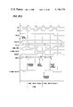
- FIG. 18b is a timing chart of Direct Memory access (DMA) Read and Write cycles
- FIG. 19a is a logic schematic of the CPU clock
- FIG. 19b is a chart illustrating the output wave form of the clock shown in FIG. 19a;
- FIG. 20 is a logic schematic of the CPU memory
- FIG. 21 is a logic schematic of the CPU memory ready
- FIGS. 22a, 22b, 22c are logic schematics of the CPU power supply stages
- FIGS. 23a and 23b comprise a block diagram of the controller I/O module
- FIG. 24 is a logic schematic of the nonvolatile memory power supply
- FIG. 25 is a block diagram of the apparatus interface and remote output connections
- FIG. 26 is a block diagram of the CPU interface module
- FIG. 27 is a block diagram of the apparatus special circuits module
- FIG. 28 is a block diagram of the main panel interface module
- FIG. 29 is a block diagram of the input matrix module
- FIG. 30 is a block diagram of a typical remote
- FIG. 31 is a block diagram of the sorter remote
- FIG. 32 is a view of the control console for inputting copy run instructions to the apparatus shown in FIG. 1;
- FIG. 33 is a flow chart illustrating a typical machine state
- FIG. 34 is a flow chart of the machine state routine
- FIG. 35 is a view showing the event table layout
- FIG. 36 is a chart illustrating the relative timing sequences of the clock interrupt pulses
- FIG. 37 is a flow charge of the pitch interrupt routine
- FIG. 38 is a flow chart of the machine clock interrupt routine
- FIGS. 39a and 39b comprise a flow chart of the real time interrupt routines
- FIGS. 40a, 40b, 40c comprise a timing chart of the principal operating components of the host machine in an exemplary copy run
- FIGS. 41-42, 43a and 43b are flow charts which illustrate the sequence of events for entering the machine into a diagnostic program, as well as determining whether the user has access to the particular program requested;
- FIG. 44 is a flow chart which illustrates the operation of a diagnostic program for displaying document travel times in the document handler
- FIGS. 45a and 45b are flow charts which illustrate the operation of a diagnostic program for continuously cycling documents through the document handler and, if desired, displaying successive document travel times between various stations therein;
- FIGS. 46a and 46b are flow charts which illustrate the operation of a diagnostic program which automatically moves documents to preselected stations in the document handler to check for proper alignment.
- FIGS. 1-3 of the drawings there is shown, in schematic outline, an electrostatic reproduction system or host machine, identified by numeral 10, incorporating the control arrangement of the present invention.
- the reproduction system 10 is divided into a main electrostatic xerographic processor 12, sorter 14, document handler 16, and controller 18.
- processor, sorter and/or document handler types and constructions, and different combinations thereof may instead by envisioned.
- Processor 12 utilizes a photoreceptor in the form of an endless photoconductive belt 20 supported in generally triangular configuration by rolls 21, 22, 23.
- Belt supporting rolls 21, 22, 23 are in turn rotatably journaled on subframe 24.
- belt 20 comprises a photoconductive layer of selenium, which is the light receiving surface and imaging medium, on a conductive substrate.
- photoreceptor types and forms such as comprising organic materials or of multi-layers or a drum may instead be envisioned.
- Still other forms may comprise scroll type arrangements wherein webs of photoconductive material may be played in and out of the interior of supporting cylinders.
- Suitable biasing means are provided on subframe 24 to tension the photoreceptor belt 20 and insure movement of belt 20 along a prescribed operating path.
- Belt tracking switch 25 (shown in FIG. 2) monitors movement of belt 20 from side to side.
- Belt 20 is supported so as to provide a trio of substantially flat belt runs opposite exposure, developing, and cleaning stations 27, 28, 29 respectfully.
- vacuum platens 30 are provided under belt 20 at each belt run.
- Conduits 31 communicate vacuum platens 30 with a vacuum pump 32.
- Photoconductive belt 20 moves in the direction indicated by the solid line arrow, drive thereto being effected through roll 21, which in turn is driven by main drive motor 34, as seen in FIG. 4.
- Processor 12 includes a generally rectangular, horizontal transparent platen 35 on which each original 2 to be copied is disposed.
- a two or four sided illumination assembly consisting of internal reflectors 36 and flash lamps 37 (shown in FIG. 2) disposed below and along at least two sides of platen 35, is provided for illuminating the original 2 on platen 35.
- the assembly is coupled through conduit 33 with a vacuum pump 38 which is adapted to withdraw overly heated air from the space.
- a platen cover 35' may be provided.
- the light image generated by the illumination system is projected via mirrors 39, 40 and a variable magnification lens assembly 41 onto the photoreceptive belt 20 at the exposure station 27.
- Reversible motor 43 is provided to move the main lens and add on lens elements that comprise the lens assembly 41 to different predetermined portions and combinations to provide the preselected image sizes corresponding to push button selectors 818, 819, 820 on operator module 800. (See FIG. 32)
- Sensors 116, 117, 118 signal the present disposition of lens assemby 41.
- Exposure of the previously charged belt 20 selectively discharges the photoconductive belt to produce on belt 20 an electrostatic latent image of the original 2.
- belt 20 is uniformly charged to a preselected level by charge corotron 42 upstream of the exposure station 27.
- Lamp 44 which is referred to herein as the pitch fadeout lamp, is supported in transverse relationship to belt 20, lamp 44 extending across substantially the entire width of belt 20 to erase (i.e. discharge) areas of belt 20 before the first image, between successive images, and after the last image.
- Lamps 45 which are referred to herein as edge fadeout lamps, serve to erase areas bordering each side of the images.
- edge fadeout lamps 45 which extend transversely to belt 20, are disposed within a housing 46 having a pair of transversely extending openings 47, 47' of differing length adjacent each edge of belt 20.
- magnetic brush rolls 50 are provided in a developer housing 51 at developing station 28.
- Housing 51 is pivotally supported adjacent the lower end thereof with interlock switch 52 to sense disposition of housing 51 in operative position adjacent belt 20.
- the bottom of housing 51 forms a sump within which a supply of developing material is contained.
- a rotatable auger 54 in the sump area serves to mix the developing material and bring the material into operative relationship with the lowermost of the magnetic brush rolls 50.
- the electrostatically attractable developing material commonly used in magnetic brush developing apparatus of the type shown comprises a pigmented resinous powder, referred to as toner, and larger granular beads referred to as carrier.
- the carrier is comprised of a magnetizable material such as steel.
- Magnetic brush rolls 50 each comprise a rotatable exterior sleeve 55 with relatively stationary magnet 56 inside.
- Sleeves 55 are rotated in unison and at substantially the same speed as belt 20 by a developer drive motor 57 through a belt and pulley arrangement 58.
- a second belt and pulley arrangement 59 drives auger 54.
- magnetic brush sleeves 55 are electrically biased.
- a suitable power supply 60 is provided for this purpose with the amount of bias being regulated by controller 18.
- Developing material is returned to the upper portion of developer housing 51 for reuse.
- a photocell 62 monitors the level of developing material in housing 51 with lamp 62' therefor spaced opposite to the photocell 62.
- the disclosed machine is also provided with automatic developability control which maintains an optimum proportion of toner-to-carrier material by sensing toner concentration and replenishing toner, as needed.
- the automatic develpability control comprises a pair of transparent plates 64 mounted in spaced, parallel arrangement in developer housing 51 such that a portion of the returning developing material passes therebetween.
- a suitable circuit not shown, alternately places a charge on the plates 64 to attract toner thereto.
- Photocell 65 on one side of the plate pair senses the developer material as the material passes therebetween.
- Lamp 65' on the opposite side of plate pair 64 provides reference illumination.
- the returning developing material is alternately attracted and repelled to and from plates 64.
- the accumulation of toner, i.e. density determines the amount of light transmitted from lamp 65' to photocell 65.
- Photocell 65 monitors the density of the returning developing material with the signal output therefrom being used by controller 18 to control the amount of fresh or make-up toner to be added to developer housing 51 from toner supply container 67.
- rotatable dispensing roll 68 is provided in the inlet to developer housing 51.
- Motor 69 drives roll 68.
- controller 18 actuates motor 69 to turn roll 68 for a timed interval.
- the rotating roll 68 which is comprised of a relatively porous sponge-like material, carries toner particles thereon into developer housing 51 where it is discharged.
- Pre-transfer corotron 70 and lamp 71 are provided downstream of magnetic brush rolls 50 to regulate developed image charges before transfer.
- a magnetic pick-off roll 72 is rotatably supported opposite belt 20 downstream of pre-transfer lamp 71, roll 72 serving to scavenge leftover carrier from belt 20 preparatory to transfer of the developed image to the copy sheet 3.
- Motor 73 turns roll 72 in the same direction and at substantially the same speed as belt 20 to prevent scoring or scratching of belt 20.
- One type of magnetic pick-off roll is shown in U.S. Pat. No. 3,834,804, issued Oct. 10, 1974 to Bhagat et al.
- Transfer roll 75 which forms part of the copy sheet feed path, is rotatably supported within a transfer roll housing 76 opposite belt support roll 21. Housing 76 is pivotally mounted for swinging movement about axis 76' to permit the transfer roll assembly to be moved into and out of operative relationship with belt 20.
- a transfer roll cleaning brush 77 is rotatably journalled in transfer roll housing 76 with the brush periphery in contact with transfer roll 75. Transfer roll 75 is driven through contact with belt 20 while cleaning brush 77 is coupled to main driven motor 34.
- housing 76 is connected through conduit 78 with vacuum pump 81.
- a suitable electrical bias is applied to transfer roll 75.
- cam 79 is provided in driving contact with transfer roll housing 76.
- Cam 79 is driven from motor 34 through an electromagnetically operated one revolution clutch 80.
- Spring means (not shown) serves to maintain housing 76 in driving engagement with cam 79.
- a detack corotron 82 is provided.
- Corotron 82 generates a charge designed to neutralize or reduce the charges tending to retain the copy sheet on belt 20.
- Corotron 82 is supported on transfer roll housing 76 opposite belt 20 and downstream of transfer roll 75.
- a cleaning brush 85 rotatably supported within an evacuated semi-circular shaped brush housing 86 at cleaning station 29, serves to remove residual developer from belt 20.
- Motor 95 drives brush 85, brush 85 turning in a direction opposite that of belt 20.
- Vacuum conduit 87 couples brush housing 86 through a centrifugal type separator 88 with the suction side of a vacuum pump 93.
- a final filter 89 on the outlet of pump 93 traps particles that pass through separator 88.
- the heavier toner particles separated by separator 88 drop into and are collected in one or more collecting bottles 90.
- Pressure sensor 91 monitors the condition of final filter 89 while a sensor 92 monitors the amount of toner particles in collecting bottles 90.
- a deflector 96 is provided upstream of cleaning brush 85.
- Deflector 96 which is pivotally supported on the brush housing 86, is operated by solenoid 97. In the normal or off position, deflector 96 is spaced from belt 20 (the solid line position shown in the drawings). Energization of solenoid 97 pivots deflector 96 downwardly to bring the deflector leading edge into close proximity to belt 20.
- Sensors 98, 99 are provided on each side of deflector 96 for sensing the presence of copy material on belt 20.
- a signal output from upstream sensor 98 triggers solenoid 97 to pivot deflector 96 into position to intercept the copy sheet on belt 20.
- the signal from sensor 98 also initiates a system shutdown cycle (mis-strip jam) wherein the various operating components are, within a prescribed interval, brought to a stop. The interval permits any copy sheet present in fuser 150 to be removed, sheet trap solenoid 158 (FIG. 12) having been actuvated to prevent the next copy sheet from entering fuser 150 and becoming trapped therein.
- the signal from sensor 99 indicating failure of deflector 96 to intercept or remove the copy sheet from belt 20, triggers an immediate or hard stop (sheet on selenium jam) of the processor. In such instances the power to drive motor 34 is interrupted to bring belt 20 and the other components driven therefrom to an immediate stop.
- copy sheets 3 comprise precut paper sheets supplied from either main or auxiliary paper trays 100, 102.
- Each paper tray has a platform or base 103 for supporting in stack-like fashion a quantity of sheets.
- the tray platforms 103 are supported for vertical up and down movement by motors 105, 106 being provided to raise and lower the platform.
- Side guide pairs 107, in eacy tray 100, 102 delimit the tray side boundaries, the guide pairs being adjustable toward and away from one another in accommodation of different size sheets.
- Sensors 108, 109 respond to the position of each side guide pair 107, the output of sensors 108, 109 serving to regulate operation of edge fadeout lamps 45 and fuser cooling valve 171 (FIG. 3).
- Lower limit switches 110 on each tray prevent overtravel of the tray platform in a downward direction.
- a heater 112 is provided below the platform 103 of main tray 100 to warm the tray area and enhance feeding of sheets therefrom. Humidstat 113 and thermostat 114 control operation of heater 112 in response to the temperature/humidity conditions of main tray 100. Fan 115 is provided to circulate air within tray 100.
- Feeders 120, 121 each include a nudger roll 123 to engage and advance the topmost sheet in the paper tray forward into the nip formed by a feed belt 124 and retard roll 125.
- Retard rolls 125 which are driven at an extremely low speed by motor 126, cooperate with feed belts 124 to restrict feeding of sheets from trays 100, 102 to one sheet at a time.
- Feed belts 124 are driven by main and auxiliary sheet feed motors 127, 128 respectively.
- Nudger rolls 123 are supported for pivotal movement about the axis of feed belt drive shaft 129 with drive to the nudger rolls taken from drive shaft 129.
- Stack height sensors 133, 134 are provided for the main and auxiliary trays, the pivoting nudger rolls 123 serving to operate sensors 133, 134 in response to the sheet stack height.
- Main and auxiliary tray misfeed sensors 135, 136 are provided at the tray outlets.
- Main transport 140 extends from main paper tray 100 to a point slightly upstream of the nip formed by photoconductive belt 20 and transfer roll 75. Transport 140 is driven from main motor 34. To register sheets 3 with the images developed on belt 20, sheet register fingers 141 are provided, fingers 141 being arranged to move into and out of the path of the sheets on transport 140 once each revolution (see also FIG. 4). Registration fingers 141 are driven from main motor 34 through electromagetic clutch 145 (seen in FIG. 4). A timing or reset switch 146 is set once on each revolution of sheet register fingers 141. Sensor 139 monitors transport 140 for jams. Further amplification of sheet register system may be found in U.S. Pat. No. 3,781,004, issued Dec. 25, 1973 to Buddendeck et al.
- Pinch roll pair 142 is interspaced between transport belts that comprise main transport 140 on the downstream side of register fingers 141. Pinch roll pair 142 are driven from main motor 34.
- Auxiliary transport 47 extends from auxiliary tray 102 to main transport 140 at a point upstream of sheet register fingers 141.
- Transport 147 is driven from motor 34.
- suitable guides or retainers may be provided along the belt runs.
- the image bearing sheets leaving the nip formed by photoconductive belt 20 and transfer roll 75 are picked off by belts 155 of the leading edge of vacuum transport 149.
- Belts 155 which are perforated for the admission of vacuum therethrough, ride on forward roller pair 148 and rear roll 153.
- a pair of internal vacuum plenums 151, 154 are provided, the leading plenum 154 cooperating with belts 155 to pick up the sheets leaving the belt/transfer roll nip.
- Transport 149 conveys the image bearing sheets to fuser 150.
- Vacuum conduits 147, 156 communicate plenums 151, 154 with vacuum pumps 152, 152'.
- a pressure sensor 157 monitors operation of vacuum pump 152.
- Sensor 144 monitors transport 149 for jams.
- a trap solenoid 158 is provided below transport 149. Energization of solenoid 158 raises the armature thereof into contact with the lower face of plenum 154 to intercept and stop the sheet moving therepast.
- fuser 150 comprises a lower heated fusing roll 160 and upper pressure roll 161. Rolls 160, 161 are supported for rotation in fuser housing 162. The core of fusing roll 160 is hollow for receipt of heating rod 163 therewithin.
- Housing 162 includes a sump 164 for holding a quantity of liquid release agent, herein termined oil.
- Dispensing belt 165 moves through sump 164 to pick up the oil, belt 165 being driven by motor 166.
- a blanket-like wick 167 carries the oil from belt 165 to the surface of fusing roll 160.
- Pressure roll 161 is supported within an upper pivotal section 168 of housing 162. This enables pressure roll 161 to be moved into and out of operative contact fusing roll 160.
- Cam shaft 169 in fuser housing 162 serves to move housing section 168 and pressure roll 161 into operative relationship with fusing roll 160 against a suitable bias (not shown).
- Cam shaft 169 is coupled to main motor 34 through an electromagnetically operated one revolution clutch 159.
- Fuser housing section 168 is evacuated.
- a conduit 170 couples housing section 168 with vacuum pump 153.
- the ends of housing section 168 are separated into vacuum compartments opposite the ends of pressure roll 161 thereunder to cool the roll ends where smaller size copy sheets 3 are being processed.
- Vacuum valve 171 (FIG. 3) in conduit 172 regulates communication of the vacuum compartments with vacuum pump 153' in response to the size sheets as sensed by side guide sensors 108, 109 in paper trays 100, 102.
- Fuser roll 160 is driven from main motor 34.
- Pressure roll 161 is drivingly coupled to fuser roll 160 for rotation therewith.
- Thermostat 174 (FIG. 12) in fuser housing 162 controls operation of heating rod 163 in response to temperature. Temperature sensor 175 protects against fuser over-temperature. To protect against trapping of a sheet in fuser 150 in the event of a jam, sensor 176 is provided.
- the sheet is carried by post fuser transport 180 to either discharge transport 181, or where duplex or two sided copies are desired, to return transport 182.
- Sheet sensor 183 monitors passage of the sheets from fuser 150.
- Transports 180, 181 are driven from main motor 34.
- Sensor 181' monitors transport 181 for jams.
- Suitable retaining means may be provided to retain the sheets on transports 180, 181.
- a deflector 184 when extended, directs sheets on transport 180 onto conveyor roll 185 and into chute 186 leading to return transport 182.
- Solenoid 179 when energized raises deflector 184 into the sheet path.
- Return transport 182 carries the sheets back to auxiliary tray 102.
- Sensor 189 monitors transport 182 for jams.
- Taper stops 187 of tray 102 is supported for oscillating movement.
- Motor 188 drives stops 187 back and forth tap sheets returned to auxilliary tray 102 into alignment for refeeding.
- a displaceable sheet stop 190 is provided adjacent the discharge end of chute 186.
- Stop 190 is pivotally supported for swinging movement into and out of chute 186.
- Solenoid 191 is provided to move stop 190 selectively into or out of chute 186.
- the sheet trapped in chute 186 by stop 190 is removed by pinch roll pairs 192, 193 and fed out through chute 201 onto discharge transport 181.
- Pinch roll pairs 192, 193 serve to draw the sheet trapped in chute 186 by stop 190 and carry the sheet forward onto discharge transport 181. Further description of the inverter mechanism may be found in U.S. Pat. No. 3,856,295, issued Dec. 24, 1974, to John H. Looney.
- Output tray 195 receives unsorted copies.
- Transport 196 a portion of which is wrapped around a turn around roll 197, serves to carry the finished copies to tray 195.
- Sensor 194 monitors transport 196 for jams.
- a deflector 198 is provided to route copies into output tray 195.
- Deflector solenoid 199 when energized, turns deflector 198 to intercept sheets on conveyor 181 and route the sheets onto conveyor 196.
- sorter 14 comprises upper and lower bin arrays 210, 211.
- Each bin array 210, 211 consists of series of spaced downwardly inclined trays 212, forming a series of individual bins 213 for receipt of finished copies 3'.
- Conveyors 214 along the top of each bin array cooperate with idler rolls 215 adjacent the inlet to each bin to transport the copies into juxtaposition with the bins.
- Individual defelctors 216 at each bin cooperate, when depressed, with the adjoining idler roll 215 to turn the copies into the bin associated therewith.
- An operating solenoid 217 is provided for each deflector.
- a driven roll pair 218 is provided at the inlet to sorter 14.
- a generally vertical conveyor 219 serves to bring copies 3' to the upper bin array 210.
- Entrance deflector 220 routes the copies selectively to either the upper or lower bin array 210, 211 respectively.
- Solenoid 221 operates deflector 220.
- Motor 222 is provided to drive the conveyors 214 and 219 of upper bin array 210 and conveyor 214 of lower bin array 211.
- Roll pair 218 is drivingly coupled to both motor 222.
- a photoelectric type sensor 225, 226 is provided at one end of each bin array 210, 211 respectively. Sensor lamps 225', 226' are disposed adjacent the other end of the bin array.
- a second set of photoelectric type sensors 227, 228 is provided for each bin array, on a level with a tray cutout (not shown). Sensor lamps 227', 228' are disposed opposite sensors 227, 228.
- document handler 16 includes a tray 233 into which originals or documents 2 to be copied are placed by the operator following which a cover (not shown) is closed.
- a movable bail or separator 235 driven in an oscillatory path from motor 236 through a solenoid operated one revolution clutch 238, is provided to maintain document separation.
- a document feed belt 239 is supported on drive and idler rolls 240, 241 and kicker roll 242 under tray 233, tray 233 being suitably apertured to permit the belt surface to project therewithin.
- Feedbelt 239 is driven by motor 236 through electromagnetic clutch 244.
- Guide 245, disposed near the discharge end of feed belt 239, cooperates with belt 239 to form a nip between which the documents pass.
- a photoelectric type sensor 246 is disposed adjacent the discharge end of belt 239. Sensor 246 responds on failure of a document to feed within a predetermined interval to actuate solenoid 248 to raise kicker roll 242 and increases the surface area of feed belt 239 in contact with the documents.
- Another sensor 259 located underneath tray 233 provides an output signal when the last document 2 of each set has left the tray 233.
- Document guides 250 route the document fed from tray 233 via roll pair 251, 252 to platen 35.
- Roll 251 is drivingly coupled to motor 236 through electromagnetic clutch 244. Contact of roll 251 with roll 252 turns roll 252.
- Roll pair 260, 261 at the entrance to platen 35 advance the document onto platen 35, roll 260 being driven through electromagnetic clutch 262 in the forward direction.
- Contact of roll 260 with roll 261 turns roll 261 in the document feeding direction.
- Roll 260 is selectively coupled through gearset 268 with motor 236 through electromagnetic clutch 265 so that on engagement of clutch 265 and disengagement of clutch 262, roll 260 and roll 261 therewith turn in the reverse direction to carry the document back to tray 233 via return chute 276.
- One way clutches 266, 267 permit free wheeling of the roll drive shafts.
- the document leaving roll pair 260, 261 is carried by platen feed belt 270 onto platen 35, belt 270 being comprised of a suitable flexible material having an exterior surface of xerographic white.
- Belt 270 is carried about drive and idler rolls 271, 272.
- Roll 271 is drivingly coupled to motor 236 for rotation in either a forward or reverse direction through clutches 262, 265. Engagement of clutch 262 operates through belt and pulley drive 279 to drive belt in the forward direction, engagement of clutch 265 operates through drive 279 to drive belt 270 in the reverse direction.
- a register 273 is provided at the platen inlet for engagement with the document trailing edge.
- control of platen belt 270 is such that following transporting of the document onto platen 35 and beyond register 273, belt 270 is reversed to carry the document backwards against register 273.
- register 273 is retracted to an inoperative position.
- Solenoid 274 is provided for moving register 273.
- a document deflector 275 is provided to route the document leaving platen 35 into return chute 276, deflector 275 being raised by solenoid 274 when withdrawing register 273.
- platen belt 270 and pinch roll pair 260, 261 are reversed through engagement of clutch 265.
- Discharge roll pair 278, driven by motor 236, carry the returning document into tray 233.
- photoelectric type sensors 246 and 280, 281 and 282 are disposed along the document routes.
- Patter 284 is provided adjacent one end of tray 233. Patter 284 is oscillated by motor 285.
- clock 202 comprises a toothed disc 203 drivingly supported on the output shaft of main drive motor 34.
- a photoelectric type signal generator 204 is disposed astride the path followed by the toothed rim of disc 203, generator 204 producing, whenever drive motor 34 is energized, a pulse like signal output at a frequency correlated with the speed of motor 34.
- a second machine clock termed a pitch reset clock 138 herein, and comprising timing switch 146 is provided.
- Switch 146 cooperates with sheet register fingers 141 to generate an output pulse once each revolution of fingers 141.
- the pulse like output of the pitch reset clock is used to reset or resynchronize controller 18 with host machine 10.
- a document handler clock 286 consisting of apertured disc 287 on the output shaft of document handler drive motor 236 and cooperating photoelectric type signal generator 288 is provided.
- document handler clock 286 produces an output pulse train from which components of the document handler may be synchronized.
- a real time clock such as clock 552 of FIG. 17, is utilized to control internal operations of the controller 18 as is known in the art. The real time clock is also utilized to time the operation of some of the machine components as will be described.
- controller 18 includes a Central Processor Unit (CPU) Module 500, Input/Output (I/O) Module 502, and Interface 504. Address, Data and Control Buses 507, 508, 509 respectively operatively couple CPU Module 500 and I/O Module 502.
- CPU Module 500 I/O Module 502 are disposed within a shield 518 to prevent noise interference.
- Interface 504 couples I/O Module 502 with special circuits module 522, input matrix module 524, and main panel interface module 526. Module 504 also couples I/O Module 502 to the operating sections of the machine, namely, document handler section 530, input section 532, sorter section 534 and processor sections 536, 538. A spare section 540, which may be used for monitoring operation of the host machine, or which may be later utilized to control other devices, is provided.
- CPU module 500 comprises a processor 542 such as an Intel 8080 microprocessor manufactured by Intel Corporation, Santa Clara, Calif., 16K Read Only Memory (herein ROM) and 2K Random Access Memory (herein RAM) sections 545, 546, Memory Ready section 548, power regulator section 550, and onboard clock 552.
- Bipolar tri-state buffers 510, 511 in Address and Data buses 507, 508 disable the bus on a Direct Memory access (DMA) signal (HOLDA) as will appear. While the capacity of memory sections 545, 546 are indicated throughout as being 16K and 2K respectively, other memory sizes may be readily contemplated.
- DMA Direct Memory access
- clock 552 comprises a suitable clock oscillator 553 feeding a multi-bite (Qa-Qn) shift register 554.
- Register 554 includes an internal feedback path from one bit to the serial input of register 554. Output signal waveforms ⁇ 1 , ⁇ 2 , ⁇ 1-1 and ⁇ 2-1 are produced for use by the system.
- the memory bytes in ROM section 545 are implemented by address signals (Ao-A 15) from processor 542, selection being effected by 3 to 8 decode chip 560 controlling chip select 1 (CS-1) and a 1 bit selection (A 13) controlling chip select 2 (CS-2).
- the most significant address bits (A 14, A 15) select the first 16K of the total 64 bytes of the addressing space.
- the memory bytes in RAM section 546 are implemented by Address signals (Ao-A 15) through selector circuit 561. Address bit A 10 serves to select the memory bank while the remaining five most significant bits (A 11-A 15) select the last 2K bytes out of the 64K bytes of addressing space.
- RAM memory section 546 includes a 40 bit output buffer (DATA OUT) the output of which is tied together with the output from ROM memory section 545 and goes to tri-state buffer 562 to drive Data bus 508.
- Buffer 562 is enabled when either memory section 545 or 546 is being addressed and either a (MEM READ) or DMA (HOLD A) memory request exists.
- An enabling signal (MEMEN) is provided from the machine control or service panel (not shown) which is used to permit disabling of buffer 562 during servicing of CPU Module 500.
- Write control comes from either processor 542 (MEM WRITE) or from DMA (HOLD A) control.
- Tri-state buffers 563 permit Refresh Control 605 of I/O Module 502 (FIG. 23b) to access MEM READ and MEM WRITE control channels directly on a DMA signal (HOLD A) from processor 542 as will appear.
- memory ready section 548 provides a READY signal to processor 542.
- a binary counter 566 which is initialized by a SYNC signal ( ⁇ ,) to a prewired count as determined by input circuitry 567, counts up at a predetermined rate. At the maximum count, the output at gate 568 comes true stopping the counter 566. If the cycle is a memory request (MEM REQ) and the memory location is on board as determined by the signal (MEM HERE) to tri-state buffer 569, a READY signal is sent to processor 542.
- Tri-state buffer 570 in MEM REQ line permits Refresh Control 605 of I/O Module 502 to access the MEM REQ channel directly on a DMA signal (HOLD A) from processor 542 as will appear.
- power regulators 550, 551, 552 provide the various voltage levels, i.e. +5 v, +12 v, -5 v D.C. required by the module 500.
- Each of the three on board regulators 550, 551, 552 employ filtered D.C. inputs.
- Power Not Normal (PNN) detection circuitry 571 is provided to reset processor 542 during the power up time. Reset control from the machine service panel (not shown) is also provided via PNN.
- An enabling signal (INHIBIT RESET) from Memory Control 638 allows completion of a write cycle in Non Volatile (N.V.) Memory 610 of I/O Module 502.
- HOLD Direct Memory Access
- Refresh Control 605 FIG. 23b
- HOLD A HOLD ACKNOWLEDGE
- I/O Module 502 interfaces with CPU module 500 through bi-directional Address and, Data buses 507, 508, respectively, and Control bus, 509. I/O Module 502 appears to CPU module 500 as a memory portion. Data transfers between CPU and I/O modules 500, 502, and commands to I/O module 502 except for output refresh are controlled by memory reference intructions executed by CPU module 500. Output refresh which is initiated by one of several uniquely decoded memory reference commands, enables Direct Memory access (DMA) by I/O module 502 of RAM section 546.
- DMA Direct Memory access
- I/O module 502 includes Matrix Input select 604 (through which inputs from the host machine 10, are received), Refresh Control 605, Nonvolatile (NV) memory 610, Interrupt Control 612 (FIG. 23a), Watch dog Timer and failure Flag 614 and clock 570.
- a Function Decode Section 601 receives and interprets commands from CPU section 500 by decoding information on address bus 507 along with control signals from processor 542 on control bus 509. On command, decode section 601 generates control signals to perform the function indicated. These functions include (a) controlling tri-state buffers 620 to establish the direction of data flow in Data bus 508; (b) strobing data from Data bus 508 into buffer latches 622; (c) controlling multiplexer 624 to put data from Interrupt Control 612, Real Time clock register 621, Matrix Input Select 604 or N.V.
- section 601 includes logic to control and synchronize the READY control line to CPU module 500, the READY line being used to advise module 500 when data placed on the Data bus by I/O module 502 is valid.
- Watch dog timer and failure flag 614 which serves to detect certain hardwired and software malfunctions, comprises a free running counter which under normal circumstances is periodically reset by an output refresh command (REFRESH) from Function Decode Section 601. If an output refresh command is not received within a preset time interval, (i.e. 25 m sec) a fault flip flop is set and a signal (FAULT) sent to the host machine 10. The signal (FAULT) also raises the HOLD line (via Refresh Control 605) to disable CPU Module 500. Clearing of the fault flip flop may be by cycling power or generating a signal (RESET). A selector (not shown) may be provided to disable (DISABLE) the watch dog timer when desired. The fault flip flop may also be set by a command from the CPU Module to indicate that the operating program detected a fault.
- REFRESH output refresh command
- Matrix Input select 604 which controls receipt of data from host machine 10 has capacity to read up to 32 groups of 8 discrete inputs from host machine 10. Lines A 3 through A 7 of Address bus 507 are routed to host machine 10 via CPU Interface Module optical isolator 569 and 504 to select the desired group of 8 inputs. The selected inputs from machine 10 are received by matrix 604 via Input Matrix Module 524 (FIG. 28) and are placed by matrix 604 onto data bus 508 and sent to CPU Module 500 via multiplexer 624. Bit selection is effected by lines A 0 through A 2 of Address bus 507.
- Output refresh control 605 when initiated, transfers either 16 or 32 sequential words from the memory output buffer (DATA OUT) of RAM memory section 546 to host machine 10 at the predetermined clock rate in line 574.
- Direct Memory access (DMA) is used to facilitate transfer of the data at a relatively high rate.
- Refresh Control 605 On a Refresh signal from Function Decode Section 601, Refresh Control 605 generates a HOLD signal to processor 542.
- HOLD A On acknowledgement (HOLD A) processor 542 enters a hold condition. In this mode, CPU Module 500 releases address and data buses 507, 508 through actuation of tri-state buffers 510, 511 as described to the high impedance state giving I/O module 502 control thereover.
- I/O module 502 then sequentially accesses the 32 memory words from output buffer (DATA OUT) of RAM section 546 (REFRESH ADDRESS) and transfers the contents to the host machine 10 via data bus 508 and optical isolator 569.
- CPU Module 500 is dormant during this period.
- LOAD Refresh Control 605
- CLOCK clock signal
- the data may be stored in addressable latches and distributed in parallel directly to the required destinations.
- N.V. memory 610 comprises a predetermined number of bits of non-volatile memory stored in I/O module 502 under Memory Control 638.
- N.V. memory 610 appears to CPU module 500 as part of the CPU module memory complement and therefore may be accessed by the standard CPU memory reference instruction set.
- CMOS protective circuitry 636 couples batteries 635 to memory 610 to preserve memory 610 on a failure of the system power.
- a logic signal (INHIBIT RESET) prevents the CPU Module 500 from being reset during the N.V. memory write cycle interval so that any write operation in progress will be completed before the system is shut down.
- a multiple interrupt system For tasks that require frequent servicing, high speed response to external events, or synchronization with the operation of host machine 10, a multiple interrupt system is provided. These comprise machine based interrupts, herein referred to as Pitch Reset interrupt and the Machine interrupt, as well as a third clock driven interrupt, the Real Time interrupt.
- Pitch reset signal 640 is generated by the signal output of pitch reset clock 138.
- the clock signal is fed via optical isolator 645 and digital filter 646 to edge tripper flip flop 647.
- the second highest priority interrupt signal is sent directly from machine clock 202 through isolation transformer 648 to a phase locked loop 649.
- Loop 649 which serves as bandpath filter and signal conditioner, sends a square wave signal to edge trigger flip flop 651.
- the second signal output (LOCK) serves to indicate whether loop 649 is locked onto a valid signal input or not.
- the lowest priority interrupt signal, Real Time Clock signal 643, is generated by register 621.
- Register 621 which is loaded and stored by memory reference instructions from CPU module 500 is decremented by a clock signal in line 643 which may be derived from I/O Module clock 570, which is driven, in turn, by clock 552. On the register count reaching zero, register 621 sends an interrupt signal to edge trigger flip flop 656.
- a spare interrupt 642 is also provided.
- processor 542 issues a signal (INTA) transferring the status of the edge trigger flip flops 647, 651, 654, 656 to a four bit latch 660 to generate an interrupt instruction code (RESTART) onto the data bus 508.
- INTA interrupt instruction code
- Each interrupt is assigned a unique RESTART instruction code. Should an interrupt of higher priority be triggered, a new interrupt signal (INT) and RESTART instruction code are generated resulting in a nesting of interrupt software routines whenever the interrupt recognition circuitry is enabled within the CPU 500.
- INT interrupt signal
- RESTART instruction code are generated resulting in a nesting of interrupt software routines whenever the interrupt recognition circuitry is enabled within the CPU 500.
- Priority chip 659 serves to establish a handling priority in the event of simultaneous interrupt signals in accordance with the priority schedule described.
- each interrupt subroutine serves, in addition to performing the functions programmed, to reset the flip flops (through the writing of a coded byte in a uniquely selected address) and to re-enable the interrupt (through execution of a re-enabling instruction). Until re-enabled, initiation of a second interrupt is precluded while the first interrupt is in progress.
- Lines 658 permit interrupt status to be interrogated by CPU module 500 on a memory reference instruction.
- I/O Module 502 includes a suitable pulse generator or clock 570 for generating the various timing signals required by module 502.
- Clock 570 is driven by the pulse-like output ⁇ 1-1 , ⁇ 2-1 of processor clock 552 (FIG. 19a).
- clock 570 provides a reference clock pulse (in line 574) for synchronizing the output refresh data and is the source of clock pulses (in line 643) for driving Real Time register 621.
- CPU interface module 504 interfaces I/O module 502 with the host machine 10 and transmits operating data stored in RAM section 546 to the machine. Referring particularly to FIGS. 25 and 26, data and address information are inputted to module 504 through suitable means such as optical type couplers 700 which convert the information to single ended logic levels. Data in bus 508 on a signal from Refresh Control 605 in line 607 (LOAD), is clocked into module 546 at the reference clock rate in line 574 parallel by bit, serial by byte for a preset byte length, with each data bit of each successive byte being clocked into a separate data channel D0-D7. As best seen in FIG.
- LOAD Refresh Control 605 in line 607
- each data channel D0-D7 has an assigned output function with data channel D0 being used for operating the front panel lamps 830 in the digital display, (see FIG. 32), data channel D1 for special circuits module 522, and remaining data channels D2-D7 allocated to the host machine operating sections 530, 532, 534, 536, 538 and 540. Portions of data channels D1-D7 have bits reserved for front panel lamps and digital display.
- bit buffer 703 (FIG. 26) is preferably provided to catch any bit overflow in data channels D2-D7.
- the machine output sections 530, 532, 534, 536, 538 and 540 are electrically a long distance away, i.e. remote, from CPU interface module 504, and the environment is electrically "noisy"
- the data stream in channels D2-D7 is transmitted to remote sections 530, 532, 534, 536, 538 and 540 via a shielded twisted pair 704.
- induced noise appears as a differential input to both lines and is rejected.
- the associated clock signal for the data is also transmitted over line 704 with the line shielded carrying the return signal currents for both data and clock signals.
- Data in channel D 1 destined for special circuits module 522 is inputted to shift register type storage circuitry 705 for transmittal to module 522.
- Display data D 0 -D 7 is also inputted to main panel interface module 526.
- Address information in bus 507 is converted to single ended output by couplers 700 and transmitted to Input Matrix Module 524 to address host machine inputs.
- CPU interface module 504 includes fault detector circuitry 706 for monitoring both faults occurring in host machine 10 and faults or failures along the buses, the latter normally comprising a low voltage level or failure in one of the system power lines.
- Machine faults may comprise a fault in CPU module 500, a belt mistrack signal from sensor 27 (see FIG. 2), opening one of the machine doors or covers as responded to by conventional cover interlock sensors (not shown), a fuser over temperature as detected by sensor 175, etc.
- a reset signal RESET
- CPU module 500 see FIGS. 17 and 18a
- a signal is generated in line 710 to actuate a suitable relay (not shown) controlling power to all or a portion of host machine 10.
- a load disabling signal (LOAD DISBL) is inputted to DATA receiving optical couplers 700 via line 708 in the event of a fault in CPU module 500 to terminate input of data to host machine 10.
- Other fault conditions are monitored by the software background program.
- a signal is generated in line 711 to the digital display on control console 800 (via main panel interface module 526) signifying a fault.
- module 522 comprises a collection of relatively independent circuits for either monitoring operation of and/or driving various elements of host machine 10.
- Module 522 incorporates suitable circuitry 712 for amplifying the output of sensors 225, 226, 227, 228 and 280, 281, 282 of sorter 14 and document handler 16 respectively; circuitry 713 for operating fuser release clutch 159; and circuitry 714 for operating main and auxiliary paper tray feed roll clutches 130, 131 and document handler feed clutch 244.
- fuser detection circuitry 715 monitors temperature conditions of fuser 150 as responded to by sensor 174. On overheating of fuser 150, a signal (FUSOT) is generated to turn heater 163 off, actuate clutch 159 to separate fusing and pressure rolls 160, 161; trigger trap solenoid 158 to prevent entrance of the next copy sheet into fuser 150, and initiate a shutdown of host machine 10. Circuitry 715 also cycles fuser heater 163 to maintain fuser 150 at proper operating temperatures and signals (FUS-RDYT) host machine 10 when fuser 150 is ready for operation.
- FUSOT signal
- Circuitry 715 also cycles fuser heater 163 to maintain fuser 150 at proper operating temperatures and signals (FUS-RDYT) host machine 10 when fuser 150 is ready for operation.
- Circuitry 716 provides closed loop control over sensor 98 which responds to the presence of a copy sheet 3 on belt 20.
- solenoid 97 is triggered to bring deflector 96 into intercepting position adjacent belt 20.
- a backup timer (not shown) is actuated. If the sheet is lifted from the belt 20 by deflector 96 within the time allotted, a signal from sensor 99 disables the timer and a misstrip type jam condition of host machine 10 is declared and the machine is stopped. If the signal from sensor 99 is not received within the allotted time, a sheet on selenium (SOS) type jam is declared and an immediate machine stop is effected.
- SOS selenium
- Circuitry 718 controls the position (and hence the image reduction effected) by the various optical elements that comprise main lens 41 in response to the reduction mode selected by the operator and the signal inputs from lens position responsive sensors 116, 117, 118.
- the signal output of circuitry 718 serves to operate lens drive motor 43 as required to place the optical elements of lens 41 in proper position to effect the image reduction programmed by the operator.
- input matrix module 524 provides analog gates 719 for receiving data from the various host machine sensors and inputs (i.e. sheet sensors 135, 136; pressure sensor 157; etc), and data (SWITCH DATA) from the various switches on Console 800 (FRONT PANEL SWITCHES FIG. 25) module 524 serving to convert the signal input to a byte oriented output for transmittal to I/O module 502 under control of Input Matrix Select 604 (FIG. 23b).
- the byte output to module 524 is selected by address information inputted on bus 507 and decoded on module 524.
- Conversion matrix 720 which may comprise a diode array, converts the input logic signals of "0" to logic "1" true.
- Data from input matrix module 524 is transmitted via optical isolators 721 to Input Matrix Select 604 of I/O module 502 (FIG. 23b). From there, the data is transmitted through Multiplexer 624 and buffers 620 to CPU Module 500.
- main panel interface module 526 serves as interface between CPU interface module 504 and operator control console 800 for display purposes and as interface between input matrix module 524 and the console switches.
- data channels D0-D7 have data bits in each channel associated with the control console digital display or lamps. This data is clocked into buffer circuitry 723 and from there, for digital display, data in channels D1-D7 is inputted to multiplexer 724. Multiplexer 724 selectively multiplexes the data to HEX to 7 segment converter 725.
- Software controlled output drivers 726 are provided for each digit which enable the proper display digit in response to the data output of converter 725. This also provides blanking control for leading zero suppression or inter digit suppression.
- Buffer circuitry 723 also enables through anode logic 728 the common digit anode drive.
- the signal (LOAD) to latch and lamp driver control circuit 729 regulates the length of the display cycle.
- console lamps 830 data in channel D0 is clocked to shift regiser 727 whose output is connected by drivers to the console lamps.
- the machine output sections 530, 532, 534, 536, 538, 540 are interfaced with I/O module 502 by CPU interface module 504. At each interrupt/refresh cycle, data is outputted to sections 530, 532, 534, 536, 538, 540 at the clock signal rate in line 574 over data channels D2, D3, D4, D5, D6, D7 respectively.
- control recovery circuitry 744 which may comprise an inverting/non-inverting digital comparator pair and output latch is provided.
- the LOAD signal serves to lockout input of data to latches 741 while new data is being clocked into shift register 740. Removal of the LOAD signal enables commutation of the fresh data to latches 741.
- the LOAD signal also serves to start timer 745 which imposes a maximum time limit within which a refresh period (initiated by Refresh Control 605) must occur. If refresh does not occur within the prescribed time limit, timer 745 generates a signal (RESET) which sets shift register 740 to zero.
- output sections 532, 536, 538 and 540 are substantially identical to document handler section 530.
- a decode matrix arrangement consisting of a Prom encoder 750 controlling bus decoder (BUS DECODER) 751 and return decoder, 752 (RET DECODER) is provided.
- the output of decoders 751, 752 drive the sorter solenoids 217 of upper and lower bin arrays 210, 211 respectively.
- Data is inputted to encoder 750 by means of shift register 754.
- control console 800 serves to enable the operator to program or condition host machine 10 to perform the copy run of runs desired.
- various indicators on console 800 reflect the operational status of machine 10.
- Console 800 includes a bezel housing 802 suitably supported on host machine 10 at a convenient point with decorative front or face panel 803 on which the various machine programming buttons and indicators appear.
- Programming buttons include power on/off buttons 804, start print (PRINT) buttons 805, stop pring (STOP) button 806 and keyboard copy quantity selector 808.
- PRINT start print
- STOP stop pring
- a series of feature select buttons consisting of auxiliary paper tray button 810, two sided copy button 811, copy lighter button 814, and copy darker button 815, are provided.
- image size selector buttons 818, 819, 820; multiple or single document select buttons 822, 823 for operation of document handler 16; and sorter sets or stacks buttons 825, 826 are provided.
- An on/off service selector 828 is also provided for activation during machine servicing. Other buttons and selection devices are also provided as will be later described.
- Indicators comprise program display lamps 830 and displays such as READY, WAIT, SIDE 1, SIDE 2, ADD PAPER, CHECK STATUS PANEL, PRESS FAULT CODE, QUANTITY COMPLETED, CHECK DOORS, UNLOAD AUX TRAY, CHECK DOCUMENT PATH, CHECK PAPER PATH, JOB INCOMPLETE and UNLOAD SORTER. Other display information may be envisioned.
- host machine 10 is conveniently divided into a number of operational states.
- the copy control program is divided into background routines and foreground routines with operational control normally residing in the background routine or routines appropriate to the particular machine state then in effect.
- the output buffer (DATA OUT) of RAM memory section 546 is used to transfer/refresh control data to the various remote locations in host machine 10, control data from both background and foreground routines being inputted to RAM memory section 546 for subsequent transmittal to host machine 10. Transmittal/refresh of control data presently in the output buffer (DATA OUT) of section 546 is effected through Direct Memory access (DMA) under the aegis of a Machine Clock interrupt routine.
- DMA Direct Memory access
- Foreground routine control data which includes a Run Event Table built in response to the particular copy run or runs programmed, is transferred to output buffer (DATA OUT) of RAM section 546 by means of a multiple prioritized interrupt system wherein the background routine in process is temporarily interrupted while fresh foreground routine control data is inputted to the RAM output buffer following which the interrupted background routine is resumed.
- DATA OUT output buffer
- the copy control program for host machine 10 is divided into a collection of foreground tasks, some of which are driven by the several interrupt routines, and others by the background or non-interrupt routines.
- Foreground tasks are tasks that generally require frequent servicing, high speed response, or synchronization with the host machine 10.
- Background routines are related to the state of host machine 10, different background routines being performed with different machine states.
- the copy control program includes a single background software routine (STCK) composed of specific subroutines associated with the principal operating states of host machine 10 is provided.
- a byte called STATE contains a number indicative of the current operating state of host machine 10.
- the machine STATES are as follows:
- each STATE is normally divided into PROLOGUE, LOOP and EPILOGUE sections.
- entry into a given STATE normally causes a group of operations to be performed, these consisting of operations that are performed once only at the entry into the STATE.
- a CALL is made to an applications subroutine therefor. Relatively simpler operations (i.e. turning devices on or off, clering memory, presetting memory, etc.) are done directly.
- the software Initialize STATE (INIT) is entered.
- the controller is initialized and a software controlled self test subroutine is entered. If the self test of the controller is successfully passed, the System Not Ready STATE (NRDY) is entered. If not, a fault condition is signaled.
- NRDY System Not Ready STATE
- the controller moves to the System Ready State (RDY).
- RDY System Ready State
- the READY lamp on console 800 is lit and final ready checks made.
- Host Machine 10 is now ready for operation upon completion of the conditioning of the machine for the desired copy run, loading of one or more originals 2 into document handler 16 (if selected by the operator), and actuation of START PRINT button 805.
- START PRINT button 805. As will appear hereinafter, the next state is PRINT wherein the particular copy run selected is carried out.
- the controller While the machine is completing a copy run, the controller normally enters the Run Not Print State (RUNNPRT) where the controller calculates the number of copies delivered, resets various flags, stores certain machine event information in the memory, as well as generally conditioning the machine for another copy run, if desired. The controller then returns to the System Not Ready State (NRDY) to recheck for ready conditions prepatory for another copy run, with the same state sequence being repeated until the machine is turned off by actuation of POWER OFF button 804 or a malfunction inspired shutdown is triggered.
- the copy control program comprises the routines in states 0-4.
- the last state (TECH REP-5) is a machine servicing state wherein different operating programs can be accessed as will later be described.
- the machine operator uses control console 800 to condition the machine for the copy run desired. Conditioning may be done during either the System Not Ready (NRDY) or System Ready (RDY) states, although the machine will not operate during the System Not Ready state should START PRINT button 805 be pushed.
- the copy run conditioning includes selecting (using keyboard 808) the number of copies to be made, and such other ancillary features as may be desired, i.e.
- auxiliary paper tray 102 (push button 810), image size selection (push button 818, 819, 820), document handler/sorter selection (push buttons 822, 823, 825, 826), copy density (push buttons 814, 815), duplex or two sided copy button 811, etc.
- START PRINT button 805 is actuated to start the copy run selected (presuming the READY lamp is on and an original or originals 2 have been placed in tray 233 of document handler 16 if the document handler has been selected).
- controller 18 After the operator selects the various features, controller 18 enters a Digit Input routine in which the conditioning information is transferred to RAM section 546.
- the copy run conditioning data passes via Main Panel Interface Module 526 to Input Matrix Module 524 and from there is addressed through Matrix Input Select 604, Multiplexer 624, and Buffers 620 of I/O Module 502 to RAM section 546 of CPU Module 500.
- a Run Event Table (FIG. 35) comprised of foreground tasks is built for operating in cooperation with the background tasks the various components of host machine 10 in an integrated manner to produce the copies desired.
- the run Event Table is formed by controller 18 through merger of a Fixed Pitch Event Table (TABLE II) (stored in ROM 545 and Non Volatile Memory 610) and a Variable Pitch Event Table (TABLE III) in a fashion appropriate to the parameters of the job selected.
- the Fixed Pitch Event Table (TABLE II) is comprised of machine events whose operational timing is fixed during each pitch cycle such as the timing of bias to transfer roll 75, (TRN 2 CURR), actuating toner concentration sensor 65 (ADC ACT), loading roll 161 of fuser 150 (FUS*LOAD), and so forth, irrespective of the particular copy run selected.
- the Variable Pitch Table (TABLE III) is comprised of machine events whose operational timing varies with the individual copy run, i.e. timing of pitch fadeout lamp 44 (FO*ONBSE) and timing of flash illumination lamps 37 (FLSH BSE).
- variable Pitch Table is built by the Pitch Table Builder (TABLE IV) from the copy run conditioning information coupled with event address information from ROM section 545, sorted by absolute clock count (via the routine shown in TABLE V), and stored in RAM section 546 (via the routine shown in TABLE VI).
- the Fixed Pitch Event Table and Variable Pitch Table are merged with the relative clock count differences between Pitch events calculated to form a Run Event Table (TABLE VII).
- the Run Event Table consists of successive groups of individual events 851.
- Each event 851 is comprised of four data blocks, data block 852 containing the number of clock pulses (from machine clock 202) to the next schedule pitch event (REL DIFF), data block 853 containing the shift register position associated with the event (REL SR), and data blocks 854, 855 (EVENT LO) (EVENT HI) containing the address of the event subroutine.
- data blocks 852, 853 (REL DIFF) (REL SR)are set to zero.
- Data blocks 854, 855 hold the address information for the Non-Print state event.
- Control Data in the Run Event Table represents a portion of the foreground tasks and is transferred to the output buffer 546' of RAM memory section 546 by the Pitch Reset and Machine Clock interrupt routines.
- Other control data, representing foreground tasks not in the Run Event Table is transferred to RAM output buffer 546' by the Real Time Clock interrupt routine. Transfer of the remainder of the control data to output buffer 546' is by means of background (non-interrupt) routines.
- Transfer of control data from output buffer 546' of RAM memory section 546 to the various locations in host machine 10 is through output Refresh via Direct Memory access (DMA) in response to machine clock interrupt signals as will appear.
- DMA Direct Memory access
- the interrupt routines are initiated by the respective interrupt signals.
- the interrupt having the highest priority is operable only during the PRINT state, and occurs once each revolution of sheet register fingers 141 as responded to by sensor 146 of pitch reset clock 138.
- an interrupt signal is generated.
- the acknowledgement signal (INTA) from processor 542 initiates the pitch reset interrupt routine.
- the interrupt On entering the pitch reset routine, the interrupt is re-enabled and the contents of the program working registers stored. A check is made to determine if building of the Run Event Table is finished. Also checks are made to insure that a new shift register schedules have been built and at least 910 clock counts since the last pitch reset have elapsed. If not, an immediate machine shutdown is initiated.
- the shift register pointer which is the byte variable containing the address of a pre-selected shift register position (SR O)
- SR PTR shift register pointer
- SR+VALUV byte variable containing the new shift register value to be shifted in following the next pitch reset interrupt.
- the event pointer (EV*PTR), a two byte variable containing the full address of the next scheduled event, is reset to Event #1.
- the count in the C register equals the time to the first event.
- Machine Cycle Down, Normal Down, and Side One Delay checks are made, and if negative, the count on a cycle up counter (CYC UP CT) is checked. If the count is less than a predetermined control count (i.e. 5), the counter (CYC UP CT) is incremented by one. When the count on the cycle up counter equals the control count, an Image Made Flag is set.
- the cycle up counter (CYC UP CT) is reset to a preset starting count (i.e. 2).
- the pitch reset interrupt routine is exited with restoration of the working registers and resetting of pitch reset flip flop 647.
- the Machine Clock Interrupt routine which is second in priority, is operative in all operational states of host machine 10. Although nominally driven by machine clock 202, which is operative only during Print state when processor main drive motor 34 is energized, machine clock pulses are also provided by phase locked loop 649 when motor 34 is stopped.
- entry to the Machine Clock interrupt routine there shown is by a signal (INTA) from processor 542 following a machine clock interrupt signal 642 as described earlier.
- the event control register (C REG) is obtained and the working register contents stored.
- the C REG is decremented by one, the register having been previously set to a count corresponding to the next event in the Event Run Table.
- the control register (C REG) is checked for zero. If the count is not zero and is an odd number, an output refresh cycle is initiated to effect transfer/refresh of data in RAM output buffer 546' to host machine 10. If the number is even, or following an output refresh, the interrupt system is re-enabled, the machine clock interrupt flip flop 651 is reset and the working registers are restored. Return is then made to the interrupted routine.
- the Event Pointer (EV*PTR) which identifies the clock count (in data block 852) for the next scheduled event (REL DIFF), is loaded and the control register (C REG) reset to a new count equal to the time to the next event.
- the Event Pointer (EV*PTR) is incremented to the relative shift register address for the event (REL SR, data block 853), and the shift register address information is set in appropriate shift registers (B, D, E, A registers).
- the event Pointer (EV*PTR) is incremented successively to the event subroutine address information (EVENT LO) (EVENT HI) in the Event Run Table, and the address information therefrom loaded into a register pair (D & E registers).
- the Event Pointer (EV PTR) is incremented to the first data block (REL DIFF) of the next succeeding event in the Run Event Table, saved, and the register pair (H & L registers) that comprise the Event Pointer are loaded with the event subroutine address from the register pair (D & E registers) holding the information.
- the register pair (D & E registers) are set to the return address for the Event Subroutine.
- the Event Subroutine is called and the subroutine data transferred to RAM output buffer 546' for transfer to the host machine on the next Output Refresh.
- the Output Refresh cycle alluded to earlier functions, when entered, to transfer/refresh data from the output buffer of 546' RAM section 546 to host machine 10.
- Direct Memory Access is used to insure a high data transfer rate.
- Refresh Control 605 raises the HOLD line to processor 542, which on completion of the operation then in progress, acknowledges by a HOLD A signal.
- processor 542 With processor 542 in a hold mode and Address and Data buses 507, 508 released to I/O Module 502 (through operation of tri-state buffers 510, 511, 563, 570), the I/O module then sequentially accesses the output buffer 546' of RAM section 546 and transfers the contents thereof to host machine 10. Data previously transferred is refreshed.
- the Real Time Interrupt which carries the lowest priority, is active in all machine states. Primarily, the interrupt acts as an interval timer by decrementing a series of timers which in turn serve to control initiation of specialized subroutines used for control and error checking purposes.
- the Real Time interrupt routine is entered in the same manner as the interrupt routines previously described, entry being in response to a specific RESTART instruction code assigned to the Real Time interrupt.
- the interrupt On entry, the interrupt is re-enabled and the register contents stored.
- the timer pointer (PNTR) for the first class of timers i.e. 10 msec TIMERS
- PNTR timer pointer
- a control register (E REG) is loaded and a timer decrementing loop is entered for the first timer.
- the loop decrements the particular timer, increments the timer pointer (PNTR) to the location of the next timer in this class, checks the timer count, and decrements the loop counter.
- the decrementing loop routine is repeated for each timer in the class (i.e. 10 msec TIMERS) following which a control counter (CNTR) for the second group of timers (i.e. 100 msec TIMERS) is decremented by one and the count checked.
- the control counter (CNTR) is initially set to a count equal to the number of times the first timer interval is divisible into the second timer interval. For example, if the first class of timers are 10 msec timers and the second timer class are 100 msec timers, the control counter (CNTR) is set at 10 initially and decremented on each Real Time interrupt by one down to zero.
- an exemplary copy run wherein three copies of each of two simplex or one-sided originals in duplex mode is made.
- the appropriate button of copy selector 808 is set for the number of copies desired, i.e. 3 and document handler button 822, sorter select button 825 and two sided (duplex) button 811 depressed.
- the originals in this case, two simplex or one-sided originals are loaded into tray 233 of document handler 16 (FIG. 14) and the Print button 805 depressed.
- the host machine 10 enters the PRINT state and the Run Event Table for the exemplary copy run selected is built by controller 18 and stored in RAM section 546.
- the Run Event Table together with Background routines serve, via the multiple interrupt system and output refresh (through D.M.A.) to operate the various components of host machine 10 in integrated timed relationship to produce the copies programmed.
- the first original is advanced onto platen 35 by document handler 16 where, as seen in FIG. 41, three exposures (1ST FLASH SIDE 1) are made producing three latent electrostatic images on belt 20 in succession.
- the images are developed at developing station 28 and transferred to individual copy sheets fed forward (1ST FEED SIDE 1) from main paper tray 100.
- the sheets bearing the images are carried from the transfer roll/belt nip by vacuum transport 155 to fuser 150 where the images are fixed.
- the copy sheets are routed by deflector 184 (referred to as an inverter gate in the tables) to return transport 182 and carried to auxiliary tray 102.
- the image bearing sheets entering tray 102 are aligned by edge pattern 187 in preparation for refeeding thereof.
- the inverted sheet is fed onto transport 181 and into an output receptacle such as sorter 14 where, in this example, the sheets are placed in successive ones of the first three trays 212 of either the upper of lower arrays 210, 211 respectively depending on the disposition of deflector 220.
- FIGS. 41 and 42 along with the illustration of the operator console as shown in FIG. 32, a routine for selecting a desired diagnostic program will be explained. It will be remembered that the machine is normally being instructed by the copy control program comprising STATE routines numbers 0-4 shown in Table I. Each STATE routine periodically calls a Switch Scan routine (SWS@SCAN) reproduced in Table XI. To enter a diagnostic program, the operator presses diagnostic console button 801 which is read by the Switch Scan routine thereby causing it to call a Diagnostic Program Entry routine (LVDGNPRG of Table XII). This routine checks to see if there is an active diagnostic program in progress. If so, it causes the operating program to cease. Normally, there will not be another diagnostic program running. Consequently, a service flag (SER@ACT) will be set indicating that the user desires to enter a diagnostic program.
- SWS@SCAN Switch Scan routine reproduced in Table XI.
- LVDGNPRG of Table XII Diagnostic Program Entry routine
- This routine determines whether the numbers entered in the display 230 correspond to valid diagnostic program numbers. For example, if numbers 10-36 are valid diagnostic access codes and a number 52 was pushed, it would not be a valid number, with this program indicating such an error by blinking the display 230.
- NVTB@CK Nonvolatile Memory Table Check routine
- This routine first checks to determine whether the requested program number is disclosable, i.e., whether this particular program can be accessed by an operator other than the sevice personnel. For example, assume that program numbers 10-15 can be, but need not be, disclosed to the user, with the remaining programs being reserved for the service personnel. Then, if the requested program number is within the 10-15 range this routine will check particular addresses in the nonvolatile memory 610 to determine whether the service personnel has stored the access code corresponding to the requested program in the memory, i.e. disclosed the program to the user. If it has been disclosed, the display 230 is cleared and the light on the console above the diagnostic button 801 is turned on indicating that the machine is now under the control of the diagnostic program desired.
- the controller makes another check to determine whether the service key 828 has been switched on or off via the SWITCH SCAN routine and periodically called subroutines SERVICE and KEY@OFF of Table XII. Normally, only the service personnel possesses this key. When the key is turned on, all of the diagnostic programs are accessible. However, if the requested program number has not been disclosed to the user nor has the service key been switched on, the display 230 will be caused to blink thereby indicating the error. Conversely, if the program is accessible, the program number flag is set signalling the controller to execute the requested program.
- the service personnel utilizes the Progressive Operator Disclosure Program (DGN@T-33) shown in Table XV.
- DGN@T-33 Progressive Operator Disclosure Program
- This program is not disclosable to the user and can be accessed only by the service personnel through the use of his service key.
- the Switch Scan routine SWS@SCAN
- the Switch Scan routine reads the various console buttons to determine whether they have been pushed, and, in this state, sets a flag, RCALL@DGN, indicating that the Display button 809 has been pushed.
- another routine (DIGIT@TR of Table XVI) reads the numbers entered in the keyboard 808 and stores them in a register or memory location for further use.
- the Disclosure program (DGN@T@33) cause the controller to read the Display flag and calls a subroutine (VALID@33) which, in turn, checks the entered number to determine whether it is within a predetermined range. If it is not a valid number, the display 230 will blink indicating that the numberdoes not correspond to a designated program number. If this test is passed, the controller 18 interrogates the non-volatile memory 610 via routine NVTB@CK. As described above, this routine interrogates the memory to determine whether the access code for the requested routine has been stored in the memory thereby indicating that it has already been disclosed. As known in the art, the access code must be converted to binary electrical signals to be stored in the memory. If it has been disclosed, one of the console lamps 830 (READY) will be turned on. If it has not been disclosed, another lamp (JOB INCOMPLETE) is lit. Accordingly, the service personnel can determine whether a particular program has already been disclosed to the user.
- VALID@33 subroutine
- Document handler 16 includes four paper path sensors hereinafter referred to as the kick sensor 246, the wait sensor 280, the exit sensor 281, and the return sensor 282.
- each sensor senses the leading and trailing edge of the document. For example, if the photocell sensor goes from light to dark, then it is sensing a leading edge. However, if the sensor goes from dark to light, it is sensing a trailing edge.
- Each of the sensors are coupled to a free running global counter or timer, referred to as a diagnostic counter, DIAG@CT, in the tables.
- the diagnostic counter can be any of a variety of known counting devices. In the preferred embodiment, it is a specified register which is periodically set and then decremented by the machine clock signal 202.
- the controller When each sensor senses a leading or trailing edge of the document 2, the controller reads the time of the diagnostic counter and stores it in a specified address in the RAM memory 546. These times are accessed by the ADH Gap Time Diagnostic program (DGN@T@13) shown in Table XVII. This routine reads the addresses of the stored times from the Gap Time Table shown in TABLE XVIII.
- the Gap Time Table defines a plurality of stations or gap times, i.e. the time it takes for a document to travel between various preselected sensors. For example, one gap time may be the time it takes the leading edge of the document to travel from the exit sensor 281 to the return sensor 282.
- start button 805. In order to display the next gap time the operator pushes start button 805. This sets the start flag (STRT@DGN) which is picked up by the Diagnostic program. It will check if the pointer is set at the end of the table. If not, the pointer is moved to the next table location and the next gap time is calculated and displayed in the display 230 as previously described. In order to display the next gap time the start button 805 is again pushed and the next gap time is analogously displayed. This operation occurs until the pointer reaches the end of the table.
- start button 805. In order to display the next gap time the start button 805 is again pushed and the next gap time is analogously displayed. This operation occurs until the pointer reaches the end of the table.
- this routine provides the ability to continually display the gap times for each document as it travels through the document handler 16. By visually monitoring the display 230 the service personnel can readily determine whether there is an undesirable fluctuation in the gap times for the various documents. To display and monitor a different gap time, a new number is entered into keyboard 808 and the same sequence as described above is followed.
- document handler 16 will come to a halt permitting the operator to clear the documents from the ADH 16 and place the test documents on top of bail bar 235.
- an appropriate console light 830 will be activated to indicate that the ADH has been reselected and is ready for further operation.
- the document handler 16 is then cycled, moving the test documents 2 from paper tray 233 throughout the paper path cycle under the control of the ADH control routine (ADH@CTRL) of Table XXII.
- ADH@CTRL ADH control routine
- the controller checks to see if its corresponding halt flag is set. If so, the ADH is stopped.
- the Lead Edge Exit routine TABLE XXIII
- the Lead Edge Exit routine checks to see if its corresponding halt flag (ADH@29@1) is set. If so, the ADH is stopped.
- this routine provides the service personnel with the ability to visually check the documents for skew at various locations throughout the document handler 16 thereby insuring proper operation.
- the machine of the present invention has considerably more flexibility than those of the prior art. Not only is it controlled by a computer with a particular program for instructing the components in a timed sequence to make copies, but it includes other operating programs which can be selectively accessed to operate the machine in a different manner.
- the ADH Continuous Cycle Diagnostic program continuously cycles the documents through document handler 16 to pinpoint potential problem areas without making copies therefrom as normally done when the copy control program (STCK) has been accessed.
- STCK copy control program
- Other operating programs which perform different functions can be envisioned and they need not necessarily be directed to diagnosing malfunctions.
- a common machine processor such as machine processor 12
- the same processor can be utilized to make copies from original documents presented to the processor by an automatic document handler or from another input device, such as a laser beam exposure device which presents originals in the form of a modulated beam controlled by stored electronic representations of the matter to be copied.
- the timing of the machine components may be different depending on which input device is used.
- a manufacturer can market a common processor and a plurality of input/output device options.
- the processor would include the control system having a program stored therein for each possible option, with the appropriate program being accessed to control the machine depending upon the option utilized with the processor.
Abstract
An electrostatographic type copying or reproduction machine incorporating a programmable digital computer to operate various machine components. The computer includes a memory which contains a plurality of different operating programs with each program instructing the machine to operate in a different manner. Provision is made for selectively permitting the user to access the programs of lesser complexity, while providing access to all of the programs to trained service personnel. The service personnel can expand or restrict the number of programs that the user is permitted to use depending on her familiarity with the machine.
Description
This invention relates to electrostatographic xerographic type reproduction machines, and more particularly, to an improved control system for such machines.
Present day reproduction machines are extremely complex devices. They often include, in addition to the processor, input/output devices such as automatic original document handlers, sorters, staplers, and other finishing devices designed to minimize operator time in producing copies. Accordingly, these machines contain a large number of components which must be activated in a strict timed sequence to insure proper operation. It has been suggested to utilize a programmable controller or digital computer to accomplish this task. However, such computers heretofore contained only one operating program specifically designed to only control the operation of the machine to produce copies in one particular manner. Therefore, these machines have not possessed the necessary flexibility to perform other tasks which differ from the set machine operation for the particular machine configuration.
Unfortunately, as the complexity of these machines increase, so does the potential for malfunctions. Accordingly, it would be desirable to provide a means for operating the machine in a different manner, not make copies, but for diagnosing the cause of malfunction which has heretofore been a burdensome task due to the complexity of the machine.
Therefore, it is an object of this invention to provide a plurality of selectively accessible operating programs for instructing a digital computer to operate the machine in a different manner.
It is another object of this invention to provide at least one selectively accessible program for use in diagnosing machine malfunctions.
It is still another object of this invention to accomplish the above objectives wherein the operating programs are accessible through an operator console on the machine.
It is a further object of this invention to provide a plurality of diagnostic programs, only some of which are accessible by the user.
It is still another object of this invention to provide means for expanding or restricting the number of programs accessible to the user.
These and other objects of this invention are accomplished by storing at least two different operating programs in a memory, with each program instructing a computer to control the operation of machine components in a different manner. Means are also provided to permit the user to selectively access the program desired, preferably by activating selection devices in the operator console. In one embodiment, one of the programs is accessed and utilized to control the machine to make copies, whereas at least one other program operates the machine components in a preselected sequence so as to permit identification of the cause of machine malfunctions. Another feature of this invention selectively permits the operator to gain access to some of the programs, while denying access to others. Moreover, means are provided to expanding or restricting the number of programs to which the user may gain access.
Other objects and advantages will be apparent from the ensuing description and drawings in which:
FIG. 1 is a schematic representation of an exemplary reproduction apparatus incorporating the control system of the present invention;
FIG. 2 is a vertical sectional view of the apparatus shown in FIG. 1 along the image plane;
FIG. 3 is a top plane view of the apparatus shown in FIG. 1;
FIG. 4 is an isometric view showing the drive train for the apparatus shown in FIG. 1;
FIG. 5 is an enlarged view showing details of the photoreceptor edge fadeout mechanism for the apparatus shown in FIG. 1;
FIG. 6 is an enlarged view showing details of the developing mechanism for the apparatus shown in FIG. 1;
FIG. 7 is an enlarged view showing details of the developing mechanism drive;
FIG. 8 is an enlarged view showing details of the developability control for the apparatus shown in FIG. 1;
FIG. 9 is an enlarged view showing details of the transfer roll support mechanism for the apparatus shown in FIG. 1;
FIG. 10 is an enlarged view showing details of the photoreceptor cleaning mechanism for the apparatus shown in FIG. 1;
FIG. 11 is an enlarged view showing details of the fuser for the apparatus shown in FIG. 1;
FIG. 12 is a schematic view showing the paper path and sensors of the apparatus shown in FIG. 1;
FIG. 13 is an enlarged view showing details of the copy sorter for the apparatus shown in FIG. 1;
FIG. 14 is a schematic view showing details of the document handler for the apparatus shown in FIG. 1;
FIG. 15 is a view showing details of the drive mechanism for the document handler shown in FIG. 14;
FIG. 16 is a block diagram of the controller for the apparatus shown in FIG. 1;
FIG. 17 is a block diagram of the controller CPU;
FIG. 18a is a block diagram showing the CPU microprocessor input/output connections;
FIG. 18b is a timing chart of Direct Memory access (DMA) Read and Write cycles;
FIG. 19a is a logic schematic of the CPU clock;
FIG. 19b is a chart illustrating the output wave form of the clock shown in FIG. 19a;
FIG. 20 is a logic schematic of the CPU memory;
FIG. 21 is a logic schematic of the CPU memory ready;
FIGS. 22a, 22b, 22c are logic schematics of the CPU power supply stages;
FIGS. 23a and 23b comprise a block diagram of the controller I/O module;
FIG. 24 is a logic schematic of the nonvolatile memory power supply;
FIG. 25 is a block diagram of the apparatus interface and remote output connections;
FIG. 26 is a block diagram of the CPU interface module;
FIG. 27 is a block diagram of the apparatus special circuits module;
FIG. 28 is a block diagram of the main panel interface module;
FIG. 29 is a block diagram of the input matrix module;
FIG. 30 is a block diagram of a typical remote;
FIG. 31 is a block diagram of the sorter remote;
FIG. 32 is a view of the control console for inputting copy run instructions to the apparatus shown in FIG. 1;
FIG. 33 is a flow chart illustrating a typical machine state;
FIG. 34 is a flow chart of the machine state routine;
FIG. 35 is a view showing the event table layout;
FIG. 36 is a chart illustrating the relative timing sequences of the clock interrupt pulses;
FIG. 37 is a flow charge of the pitch interrupt routine;
FIG. 38 is a flow chart of the machine clock interrupt routine;
FIGS. 39a and 39b comprise a flow chart of the real time interrupt routines;
FIGS. 40a, 40b, 40c comprise a timing chart of the principal operating components of the host machine in an exemplary copy run;
FIGS. 41-42, 43a and 43b, are flow charts which illustrate the sequence of events for entering the machine into a diagnostic program, as well as determining whether the user has access to the particular program requested;
FIG. 44 is a flow chart which illustrates the operation of a diagnostic program for displaying document travel times in the document handler;
FIGS. 45a and 45b are flow charts which illustrate the operation of a diagnostic program for continuously cycling documents through the document handler and, if desired, displaying successive document travel times between various stations therein; and
FIGS. 46a and 46b are flow charts which illustrate the operation of a diagnostic program which automatically moves documents to preselected stations in the document handler to check for proper alignment.
Referring particularly to FIGS. 1-3 of the drawings, there is shown, in schematic outline, an electrostatic reproduction system or host machine, identified by numeral 10, incorporating the control arrangement of the present invention. To facilitate description, the reproduction system 10 is divided into a main electrostatic xerographic processor 12, sorter 14, document handler 16, and controller 18. Other processor, sorter and/or document handler types and constructions, and different combinations thereof may instead by envisioned.
In the exemplary processor illustrated, belt 20 comprises a photoconductive layer of selenium, which is the light receiving surface and imaging medium, on a conductive substrate. Other photoreceptor types and forms, such as comprising organic materials or of multi-layers or a drum may instead be envisioned. Still other forms may comprise scroll type arrangements wherein webs of photoconductive material may be played in and out of the interior of supporting cylinders.
Suitable biasing means (not shown) are provided on subframe 24 to tension the photoreceptor belt 20 and insure movement of belt 20 along a prescribed operating path. Belt tracking switch 25 (shown in FIG. 2) monitors movement of belt 20 from side to side. Belt 20 is supported so as to provide a trio of substantially flat belt runs opposite exposure, developing, and cleaning stations 27, 28, 29 respectfully. To enhance belt flatness at these stations, vacuum platens 30 are provided under belt 20 at each belt run. Conduits 31 communicate vacuum platens 30 with a vacuum pump 32. Photoconductive belt 20 moves in the direction indicated by the solid line arrow, drive thereto being effected through roll 21, which in turn is driven by main drive motor 34, as seen in FIG. 4.
The light image generated by the illumination system is projected via mirrors 39, 40 and a variable magnification lens assembly 41 onto the photoreceptive belt 20 at the exposure station 27. Reversible motor 43 is provided to move the main lens and add on lens elements that comprise the lens assembly 41 to different predetermined portions and combinations to provide the preselected image sizes corresponding to push button selectors 818, 819, 820 on operator module 800. (See FIG. 32) Sensors 116, 117, 118 signal the present disposition of lens assemby 41. Exposure of the previously charged belt 20 selectively discharges the photoconductive belt to produce on belt 20 an electrostatic latent image of the original 2. To prepare belt 20 for imaging, belt 20 is uniformly charged to a preselected level by charge corotron 42 upstream of the exposure station 27.
To prevent development of charged but unwanted image areas, erase lamps 44, 45 are provided. Lamp 44, which is referred to herein as the pitch fadeout lamp, is supported in transverse relationship to belt 20, lamp 44 extending across substantially the entire width of belt 20 to erase (i.e. discharge) areas of belt 20 before the first image, between successive images, and after the last image. Lamps 45, which are referred to herein as edge fadeout lamps, serve to erase areas bordering each side of the images. Referring particularly to FIG. 5, edge fadeout lamps 45, which extend transversely to belt 20, are disposed within a housing 46 having a pair of transversely extending openings 47, 47' of differing length adjacent each edge of belt 20. By selectively actuating one or the other of the lamps 45, the width of the area bordering the sides of the image that is erased can be controlled.
Referring to FIGS. 1, 6 and 7, magnetic brush rolls 50 are provided in a developer housing 51 at developing station 28. Housing 51 is pivotally supported adjacent the lower end thereof with interlock switch 52 to sense disposition of housing 51 in operative position adjacent belt 20. The bottom of housing 51 forms a sump within which a supply of developing material is contained. A rotatable auger 54 in the sump area serves to mix the developing material and bring the material into operative relationship with the lowermost of the magnetic brush rolls 50.
As will be understood by those skilled in the art, the electrostatically attractable developing material commonly used in magnetic brush developing apparatus of the type shown comprises a pigmented resinous powder, referred to as toner, and larger granular beads referred to as carrier. To provide the necessary magnetic properties, the carrier is comprised of a magnetizable material such as steel. By virtue of the magnetic fields established by developing rolls 50 and the interrelationship therebetween, a blanket of developing material is formed along the surfaces of developing rolls 50 adjacent the belt 20 and extending from one roll to another. Toner is attracted to the electrostatic latent image from the carrier bristles to produce a visible powder image on the surface of belt 20.
Magnetic brush rolls 50 each comprise a rotatable exterior sleeve 55 with relatively stationary magnet 56 inside. Sleeves 55 are rotated in unison and at substantially the same speed as belt 20 by a developer drive motor 57 through a belt and pulley arrangement 58. A second belt and pulley arrangement 59 drives auger 54.
To regulate development of the latent electrostatic images on belt 20, magnetic brush sleeves 55 are electrically biased. A suitable power supply 60 is provided for this purpose with the amount of bias being regulated by controller 18.
Developing material is returned to the upper portion of developer housing 51 for reuse. A photocell 62 monitors the level of developing material in housing 51 with lamp 62' therefor spaced opposite to the photocell 62. The disclosed machine is also provided with automatic developability control which maintains an optimum proportion of toner-to-carrier material by sensing toner concentration and replenishing toner, as needed. As shown in FIG. 8, the automatic develpability control comprises a pair of transparent plates 64 mounted in spaced, parallel arrangement in developer housing 51 such that a portion of the returning developing material passes therebetween. A suitable circuit, not shown, alternately places a charge on the plates 64 to attract toner thereto. Photocell 65 on one side of the plate pair senses the developer material as the material passes therebetween. Lamp 65' on the opposite side of plate pair 64 provides reference illumination. In this arrangement, the returning developing material is alternately attracted and repelled to and from plates 64. The accumulation of toner, i.e. density determines the amount of light transmitted from lamp 65' to photocell 65. Photocell 65 monitors the density of the returning developing material with the signal output therefrom being used by controller 18 to control the amount of fresh or make-up toner to be added to developer housing 51 from toner supply container 67.
To discharge toner from container 67, rotatable dispensing roll 68 is provided in the inlet to developer housing 51. Motor 69 drives roll 68. When fresh toner is required, as determined by the signal from photocell 65, controller 18 actuates motor 69 to turn roll 68 for a timed interval. The rotating roll 68, which is comprised of a relatively porous sponge-like material, carries toner particles thereon into developer housing 51 where it is discharged. Pre-transfer corotron 70 and lamp 71 are provided downstream of magnetic brush rolls 50 to regulate developed image charges before transfer.
A magnetic pick-off roll 72 is rotatably supported opposite belt 20 downstream of pre-transfer lamp 71, roll 72 serving to scavenge leftover carrier from belt 20 preparatory to transfer of the developed image to the copy sheet 3. Motor 73 turns roll 72 in the same direction and at substantially the same speed as belt 20 to prevent scoring or scratching of belt 20. One type of magnetic pick-off roll is shown in U.S. Pat. No. 3,834,804, issued Oct. 10, 1974 to Bhagat et al.
Referring to FIGS. 4, 9 and 12, to transfer developed images from belt 20 to the copy sheets 3, a transfer roll 75 is provided. Transfer roll 75, which forms part of the copy sheet feed path, is rotatably supported within a transfer roll housing 76 opposite belt support roll 21. Housing 76 is pivotally mounted for swinging movement about axis 76' to permit the transfer roll assembly to be moved into and out of operative relationship with belt 20. A transfer roll cleaning brush 77 is rotatably journalled in transfer roll housing 76 with the brush periphery in contact with transfer roll 75. Transfer roll 75 is driven through contact with belt 20 while cleaning brush 77 is coupled to main driven motor 34. To remove toner, housing 76 is connected through conduit 78 with vacuum pump 81. To facilitate and control transfer of the developed images from belt 20 to the copy sheets 3, a suitable electrical bias is applied to transfer roll 75.
To permit transfer roll 75 to be moved into and out of operative relationship with belt 20, cam 79 is provided in driving contact with transfer roll housing 76. Cam 79 is driven from motor 34 through an electromagnetically operated one revolution clutch 80. Spring means (not shown) serves to maintain housing 76 in driving engagement with cam 79.
To facilitate separation of the copy sheets 3 from belt 20 following transfer of developed images, a detack corotron 82 is provided. Corotron 82 generates a charge designed to neutralize or reduce the charges tending to retain the copy sheet on belt 20. Corotron 82 is supported on transfer roll housing 76 opposite belt 20 and downstream of transfer roll 75.
Referring to FIGS. 1, 2 and 10, to prepare belt 20 for cleaning, residual charges on belt 20 are removed by discharge lamp 84 and preclean corotron 94. A cleaning brush 85, rotatably supported within an evacuated semi-circular shaped brush housing 86 at cleaning station 29, serves to remove residual developer from belt 20. Motor 95 drives brush 85, brush 85 turning in a direction opposite that of belt 20.
To obviate the danger of copy sheets remaining on belt 20 and becoming entangled with the belt cleaning mechanism, a deflector 96 is provided upstream of cleaning brush 85. Deflector 96, which is pivotally supported on the brush housing 86, is operated by solenoid 97. In the normal or off position, deflector 96 is spaced from belt 20 (the solid line position shown in the drawings). Energization of solenoid 97 pivots deflector 96 downwardly to bring the deflector leading edge into close proximity to belt 20.
Referring particularly to FIGS. 1 and 12, copy sheets 3 comprise precut paper sheets supplied from either main or auxiliary paper trays 100, 102. Each paper tray has a platform or base 103 for supporting in stack-like fashion a quantity of sheets. The tray platforms 103 are supported for vertical up and down movement by motors 105, 106 being provided to raise and lower the platform. Side guide pairs 107, in eacy tray 100, 102 delimit the tray side boundaries, the guide pairs being adjustable toward and away from one another in accommodation of different size sheets. Sensors 108, 109 respond to the position of each side guide pair 107, the output of sensors 108, 109 serving to regulate operation of edge fadeout lamps 45 and fuser cooling valve 171 (FIG. 3). Lower limit switches 110 on each tray prevent overtravel of the tray platform in a downward direction.
A heater 112 is provided below the platform 103 of main tray 100 to warm the tray area and enhance feeding of sheets therefrom. Humidstat 113 and thermostat 114 control operation of heater 112 in response to the temperature/humidity conditions of main tray 100. Fan 115 is provided to circulate air within tray 100.
To advance the sheets 3 from either main or auxiliary tray 100, 102, main and auxiliary sheet feeders 120, 121 are provided. Feeders 120, 121 each include a nudger roll 123 to engage and advance the topmost sheet in the paper tray forward into the nip formed by a feed belt 124 and retard roll 125. Retard rolls 125, which are driven at an extremely low speed by motor 126, cooperate with feed belts 124 to restrict feeding of sheets from trays 100, 102 to one sheet at a time.
Feed belts 124 are driven by main and auxiliary sheet feed motors 127, 128 respectively. Nudger rolls 123 are supported for pivotal movement about the axis of feed belt drive shaft 129 with drive to the nudger rolls taken from drive shaft 129. Stack height sensors 133, 134 are provided for the main and auxiliary trays, the pivoting nudger rolls 123 serving to operate sensors 133, 134 in response to the sheet stack height. Main and auxiliary tray misfeed sensors 135, 136 are provided at the tray outlets.
Pinch roll pair 142 is interspaced between transport belts that comprise main transport 140 on the downstream side of register fingers 141. Pinch roll pair 142 are driven from main motor 34.
To maintain the sheets in driving contact with the belts of transports 140, 147, suitable guides or retainers (not shown) may be provided along the belt runs.
The image bearing sheets leaving the nip formed by photoconductive belt 20 and transfer roll 75 are picked off by belts 155 of the leading edge of vacuum transport 149. Belts 155, which are perforated for the admission of vacuum therethrough, ride on forward roller pair 148 and rear roll 153. A pair of internal vacuum plenums 151, 154 are provided, the leading plenum 154 cooperating with belts 155 to pick up the sheets leaving the belt/transfer roll nip. Transport 149 conveys the image bearing sheets to fuser 150. Vacuum conduits 147, 156 communicate plenums 151, 154 with vacuum pumps 152, 152'. A pressure sensor 157 monitors operation of vacuum pump 152. Sensor 144 monitors transport 149 for jams.
To prevent the sheet on transport 149 from being carried into fuser 150 in the event of a jam or malfunction, a trap solenoid 158 is provided below transport 149. Energization of solenoid 158 raises the armature thereof into contact with the lower face of plenum 154 to intercept and stop the sheet moving therepast.
Referring particularly to FIGS. 3, 4, 11 and 12, fuser 150 comprises a lower heated fusing roll 160 and upper pressure roll 161. Rolls 160, 161 are supported for rotation in fuser housing 162. The core of fusing roll 160 is hollow for receipt of heating rod 163 therewithin.
Thermostat 174 (FIG. 12) in fuser housing 162 controls operation of heating rod 163 in response to temperature. Temperature sensor 175 protects against fuser over-temperature. To protect against trapping of a sheet in fuser 150 in the event of a jam, sensor 176 is provided.
Following fuser 150, the sheet is carried by post fuser transport 180 to either discharge transport 181, or where duplex or two sided copies are desired, to return transport 182. Sheet sensor 183 monitors passage of the sheets from fuser 150. Transports 180, 181 are driven from main motor 34. Sensor 181' monitors transport 181 for jams. Suitable retaining means may be provided to retain the sheets on transports 180, 181.
A deflector 184, when extended, directs sheets on transport 180 onto conveyor roll 185 and into chute 186 leading to return transport 182. Solenoid 179, when energized raises deflector 184 into the sheet path. Return transport 182 carries the sheets back to auxiliary tray 102. Sensor 189 monitors transport 182 for jams. Taper stops 187 of tray 102 is supported for oscillating movement. Motor 188 drives stops 187 back and forth tap sheets returned to auxilliary tray 102 into alignment for refeeding.
To invert duplex copy sheets following fusing of the second or duplex image, a displaceable sheet stop 190 is provided adjacent the discharge end of chute 186. Stop 190 is pivotally supported for swinging movement into and out of chute 186. Solenoid 191 is provided to move stop 190 selectively into or out of chute 186. The sheet trapped in chute 186 by stop 190 is removed by pinch roll pairs 192, 193 and fed out through chute 201 onto discharge transport 181. Pinch roll pairs 192, 193 serve to draw the sheet trapped in chute 186 by stop 190 and carry the sheet forward onto discharge transport 181. Further description of the inverter mechanism may be found in U.S. Pat. No. 3,856,295, issued Dec. 24, 1974, to John H. Looney.
When output tray 195 is not used, the sheets are carried by conveyor 181 to sorter 14.
Referring particularly to FIG. 13, sorter 14 comprises upper and lower bin arrays 210, 211. Each bin array 210, 211 consists of series of spaced downwardly inclined trays 212, forming a series of individual bins 213 for receipt of finished copies 3'. Conveyors 214 along the top of each bin array, cooperate with idler rolls 215 adjacent the inlet to each bin to transport the copies into juxtaposition with the bins. Individual defelctors 216 at each bin cooperate, when depressed, with the adjoining idler roll 215 to turn the copies into the bin associated therewith. An operating solenoid 217 is provided for each deflector.
A driven roll pair 218 is provided at the inlet to sorter 14. A generally vertical conveyor 219 serves to bring copies 3' to the upper bin array 210. Entrance deflector 220 routes the copies selectively to either the upper or lower bin array 210, 211 respectively. Solenoid 221 operates deflector 220.
To detect entry of copies 3' in the individual bins 213, a photoelectric type sensor 225, 226 is provided at one end of each bin array 210, 211 respectively. Sensor lamps 225', 226' are disposed adjacent the other end of the bin array. To detect the presence of copies in the bins 213, a second set of photoelectric type sensors 227, 228 is provided for each bin array, on a level with a tray cutout (not shown). Sensor lamps 227', 228' are disposed opposite sensors 227, 228.
Referring particularly to FIGS. 14 and 15, document handler 16 includes a tray 233 into which originals or documents 2 to be copied are placed by the operator following which a cover (not shown) is closed. A movable bail or separator 235, driven in an oscillatory path from motor 236 through a solenoid operated one revolution clutch 238, is provided to maintain document separation.
A document feed belt 239 is supported on drive and idler rolls 240, 241 and kicker roll 242 under tray 233, tray 233 being suitably apertured to permit the belt surface to project therewithin. Feedbelt 239 is driven by motor 236 through electromagnetic clutch 244. Guide 245, disposed near the discharge end of feed belt 239, cooperates with belt 239 to form a nip between which the documents pass.
A photoelectric type sensor 246 is disposed adjacent the discharge end of belt 239. Sensor 246 responds on failure of a document to feed within a predetermined interval to actuate solenoid 248 to raise kicker roll 242 and increases the surface area of feed belt 239 in contact with the documents. Another sensor 259 located underneath tray 233 provides an output signal when the last document 2 of each set has left the tray 233.
Document guides 250 route the document fed from tray 233 via roll pair 251, 252 to platen 35. Roll 251 is drivingly coupled to motor 236 through electromagnetic clutch 244. Contact of roll 251 with roll 252 turns roll 252.
The document leaving roll pair 260, 261 is carried by platen feed belt 270 onto platen 35, belt 270 being comprised of a suitable flexible material having an exterior surface of xerographic white. Belt 270 is carried about drive and idler rolls 271, 272. Roll 271 is drivingly coupled to motor 236 for rotation in either a forward or reverse direction through clutches 262, 265. Engagement of clutch 262 operates through belt and pulley drive 279 to drive belt in the forward direction, engagement of clutch 265 operates through drive 279 to drive belt 270 in the reverse direction.
To locate the document in predetermined position on platen 35, a register 273 is provided at the platen inlet for engagement with the document trailing edge. For this purpose, control of platen belt 270 is such that following transporting of the document onto platen 35 and beyond register 273, belt 270 is reversed to carry the document backwards against register 273.
To remove the document from platen 35 following copying, register 273 is retracted to an inoperative position. Solenoid 274 is provided for moving register 273.
A document deflector 275, is provided to route the document leaving platen 35 into return chute 276, deflector 275 being raised by solenoid 274 when withdrawing register 273. For this purpose, platen belt 270 and pinch roll pair 260, 261 are reversed through engagement of clutch 265. Discharge roll pair 278, driven by motor 236, carry the returning document into tray 233.
To monitor movement of the documents in document handler 16 and detect jams and other malfunctions, photoelectric type sensors 246 and 280, 281 and 282 are disposed along the document routes.
To align documents 2 returned to tray 233, a document patter 284 is provided adjacent one end of tray 233. Patter 284 is oscillated by motor 285.
To provide the requisite operational synchronization between host machine 10 and controller 18 as will appear, processor or machine clock 202 is provided. Referring particularly to FIG. 1(a), clock 202 comprises a toothed disc 203 drivingly supported on the output shaft of main drive motor 34. A photoelectric type signal generator 204 is disposed astride the path followed by the toothed rim of disc 203, generator 204 producing, whenever drive motor 34 is energized, a pulse like signal output at a frequency correlated with the speed of motor 34.
As described, a second machine clock, termed a pitch reset clock 138 herein, and comprising timing switch 146 is provided. Switch 146 cooperates with sheet register fingers 141 to generate an output pulse once each revolution of fingers 141. As will appear, the pulse like output of the pitch reset clock is used to reset or resynchronize controller 18 with host machine 10.
Referring to FIG. 15, a document handler clock 286 consisting of apertured disc 287 on the output shaft of document handler drive motor 236 and cooperating photoelectric type signal generator 288 is provided. As in the case of machine clock 202, document handler clock 286 produces an output pulse train from which components of the document handler may be synchronized. A real time clock such as clock 552 of FIG. 17, is utilized to control internal operations of the controller 18 as is known in the art. The real time clock is also utilized to time the operation of some of the machine components as will be described.
Referring to FIG. 16, controller 18 includes a Central Processor Unit (CPU) Module 500, Input/Output (I/O) Module 502, and Interface 504. Address, Data and Control Buses 507, 508, 509 respectively operatively couple CPU Module 500 and I/O Module 502. CPU Module 500 I/O Module 502 are disposed within a shield 518 to prevent noise interference.
Interface 504 couples I/O Module 502 with special circuits module 522, input matrix module 524, and main panel interface module 526. Module 504 also couples I/O Module 502 to the operating sections of the machine, namely, document handler section 530, input section 532, sorter section 534 and processor sections 536, 538. A spare section 540, which may be used for monitoring operation of the host machine, or which may be later utilized to control other devices, is provided.
Referring to FIGS. 17, 18(a), CPU module 500 comprises a processor 542 such as an Intel 8080 microprocessor manufactured by Intel Corporation, Santa Clara, Calif., 16K Read Only Memory (herein ROM) and 2K Random Access Memory (herein RAM) sections 545, 546, Memory Ready section 548, power regulator section 550, and onboard clock 552. Bipolar tri-state buffers 510, 511 in Address and Data buses 507, 508 disable the bus on a Direct Memory access (DMA) signal (HOLDA) as will appear. While the capacity of memory sections 545, 546 are indicated throughout as being 16K and 2K respectively, other memory sizes may be readily contemplated.
Referring particularly to FIG. 19(a,b), clock 552 comprises a suitable clock oscillator 553 feeding a multi-bite (Qa-Qn) shift register 554. Register 554 includes an internal feedback path from one bit to the serial input of register 554. Output signal waveforms φ1,φ2,φ1-1 and φ2-1 are produced for use by the system.
Referring to FIG. 20, the memory bytes in ROM section 545 are implemented by address signals (Ao-A 15) from processor 542, selection being effected by 3 to 8 decode chip 560 controlling chip select 1 (CS-1) and a 1 bit selection (A 13) controlling chip select 2 (CS-2). The most significant address bits (A 14, A 15) select the first 16K of the total 64 bytes of the addressing space. The memory bytes in RAM section 546 are implemented by Address signals (Ao-A 15) through selector circuit 561. Address bit A 10 serves to select the memory bank while the remaining five most significant bits (A 11-A 15) select the last 2K bytes out of the 64K bytes of addressing space. RAM memory section 546 includes a 40 bit output buffer (DATA OUT) the output of which is tied together with the output from ROM memory section 545 and goes to tri-state buffer 562 to drive Data bus 508. Buffer 562 is enabled when either memory section 545 or 546 is being addressed and either a (MEM READ) or DMA (HOLD A) memory request exists. An enabling signal (MEMEN) is provided from the machine control or service panel (not shown) which is used to permit disabling of buffer 562 during servicing of CPU Module 500. Write control comes from either processor 542 (MEM WRITE) or from DMA (HOLD A) control. Tri-state buffers 563 permit Refresh Control 605 of I/O Module 502 (FIG. 23b) to access MEM READ and MEM WRITE control channels directly on a DMA signal (HOLD A) from processor 542 as will appear.
Referring to FIG. 21, memory ready section 548 provides a READY signal to processor 542. A binary counter 566, which is initialized by a SYNC signal (φ,) to a prewired count as determined by input circuitry 567, counts up at a predetermined rate. At the maximum count, the output at gate 568 comes true stopping the counter 566. If the cycle is a memory request (MEM REQ) and the memory location is on board as determined by the signal (MEM HERE) to tri-state buffer 569, a READY signal is sent to processor 542. Tri-state buffer 570 in MEM REQ line permits Refresh Control 605 of I/O Module 502 to access the MEM REQ channel directly on a DMA signal (HOLD A) from processor 542 as will appear.
Referring to FIG. 22(a,b,c) and 23b, power regulators 550, 551, 552 provide the various voltage levels, i.e. +5 v, +12 v, -5 v D.C. required by the module 500. Each of the three on board regulators 550, 551, 552 employ filtered D.C. inputs. Power Not Normal (PNN) detection circuitry 571 is provided to reset processor 542 during the power up time. Reset control from the machine service panel (not shown) is also provided via PNN. An enabling signal (INHIBIT RESET) from Memory Control 638 allows completion of a write cycle in Non Volatile (N.V.) Memory 610 of I/O Module 502.
Referring to FIGS. 18a, 20, 21, and the DMA timing chart (FIG. 18b) data transfer from RAM section 546 to host machine 10 is effected through Direct Memory Access (DMA), as will appear. To initiate DMA, a signal (HOLD) is generated by Refresh Control 605 (FIG. 23b). On acceptance, processor 542 generates a signal HOLD ACKNOWLEDGE (HOLD A) which works through tri-state buffers 510, 511 and through buffers 563 and 570 to release Address bus 507, Data bus 508 and MEM READ, MEM WRITE, and MEM REQ channels (FIGS. 20, 21) to Refresh Control 605 of I/O Module 502.
Referring to FIG. 23(a,b), I/O Module 502 interfaces with CPU module 500 through bi-directional Address and, Data buses 507, 508, respectively, and Control bus, 509. I/O Module 502 appears to CPU module 500 as a memory portion. Data transfers between CPU and I/ O modules 500, 502, and commands to I/O module 502 except for output refresh are controlled by memory reference intructions executed by CPU module 500. Output refresh which is initiated by one of several uniquely decoded memory reference commands, enables Direct Memory access (DMA) by I/O module 502 of RAM section 546.
I/O module 502 includes Matrix Input select 604 (through which inputs from the host machine 10, are received), Refresh Control 605, Nonvolatile (NV) memory 610, Interrupt Control 612 (FIG. 23a), Watch dog Timer and failure Flag 614 and clock 570.
A Function Decode Section 601 receives and interprets commands from CPU section 500 by decoding information on address bus 507 along with control signals from processor 542 on control bus 509. On command, decode section 601 generates control signals to perform the function indicated. These functions include (a) controlling tri-state buffers 620 to establish the direction of data flow in Data bus 508; (b) strobing data from Data bus 508 into buffer latches 622; (c) controlling multiplexer 624 to put data from Interrupt Control 612, Real Time clock register 621, Matrix Input Select 604 or N.V. memory 610 onto data bus 508; (d) actuating refresh control 605 to initiate a DMA operation; (e) actuating buffers 634 to enable address bits Ao-A 7 to be sent to the host machine 10 for input matrix read operations; (f) commanding operation of Matrix Input Select 604; (g) initiating read or write operation of N.V. memory 610 through Memory Control 638; (h) loading Real Time clock register 621 (FIG. 23a) from data bus 508; and (i) resetting the Watch Dog timer and setting the Fault Failure flag 614. In addition, section 601 includes logic to control and synchronize the READY control line to CPU module 500, the READY line being used to advise module 500 when data placed on the Data bus by I/O module 502 is valid.
Watch dog timer and failure flag 614, which serves to detect certain hardwired and software malfunctions, comprises a free running counter which under normal circumstances is periodically reset by an output refresh command (REFRESH) from Function Decode Section 601. If an output refresh command is not received within a preset time interval, (i.e. 25 m sec) a fault flip flop is set and a signal (FAULT) sent to the host machine 10. The signal (FAULT) also raises the HOLD line (via Refresh Control 605) to disable CPU Module 500. Clearing of the fault flip flop may be by cycling power or generating a signal (RESET). A selector (not shown) may be provided to disable (DISABLE) the watch dog timer when desired. The fault flip flop may also be set by a command from the CPU Module to indicate that the operating program detected a fault.
Matrix Input select 604 which controls receipt of data from host machine 10 has capacity to read up to 32 groups of 8 discrete inputs from host machine 10. Lines A3 through A7 of Address bus 507 are routed to host machine 10 via CPU Interface Module optical isolator 569 and 504 to select the desired group of 8 inputs. The selected inputs from machine 10 are received by matrix 604 via Input Matrix Module 524 (FIG. 28) and are placed by matrix 604 onto data bus 508 and sent to CPU Module 500 via multiplexer 624. Bit selection is effected by lines A0 through A2 of Address bus 507.
On capture of the address and data buses 507, 508, a control signal (LOAD) from Refresh Control 605 together with a clock signal (CLOCK) in line 574 are utilized to generate eight 32 bit serial words which are transmitted serially via CPU Interface Module 504 to the host machine remote locations where serial to parallel transformation is performed. Alternatively, the data may be stored in addressable latches and distributed in parallel directly to the required destinations.
N.V. memory 610 comprises a predetermined number of bits of non-volatile memory stored in I/O module 502 under Memory Control 638. N.V. memory 610 appears to CPU module 500 as part of the CPU module memory complement and therefore may be accessed by the standard CPU memory reference instruction set. Referring particularly to FIG. 24, to sustain the contents of N.V. memory 610 should system power be interrupted, one or more rechargeable batteries 635 are provided exterior to I/O module 502. CMOS protective circuitry 636 couples batteries 635 to memory 610 to preserve memory 610 on a failure of the system power. A logic signal (INHIBIT RESET) prevents the CPU Module 500 from being reset during the N.V. memory write cycle interval so that any write operation in progress will be completed before the system is shut down.
For tasks that require frequent servicing, high speed response to external events, or synchronization with the operation of host machine 10, a multiple interrupt system is provided. These comprise machine based interrupts, herein referred to as Pitch Reset interrupt and the Machine interrupt, as well as a third clock driven interrupt, the Real Time interrupt.
Referring particularly to FIG. 23(a) the highest priority interrupt signal, Pitch reset signal 640, is generated by the signal output of pitch reset clock 138. The clock signal is fed via optical isolator 645 and digital filter 646 to edge tripper flip flop 647.
The second highest priority interrupt signal, machine clock signal 641, is sent directly from machine clock 202 through isolation transformer 648 to a phase locked loop 649. Loop 649, which serves as bandpath filter and signal conditioner, sends a square wave signal to edge trigger flip flop 651. The second signal output (LOCK) serves to indicate whether loop 649 is locked onto a valid signal input or not.
The lowest priority interrupt signal, Real Time Clock signal 643, is generated by register 621. Register 621 which is loaded and stored by memory reference instructions from CPU module 500 is decremented by a clock signal in line 643 which may be derived from I/O Module clock 570, which is driven, in turn, by clock 552. On the register count reaching zero, register 621 sends an interrupt signal to edge trigger flip flop 656. A spare interrupt 642 is also provided.
Setting of one or more of the edge trigger flip flops 647, 651, 654, 656 by the interrupt signals 640, 641, 642, 643 generates a signal (INT) via priority chip 659 to processor 542 of CPU Module (FIG. 18a). On acknowledgement, processor 542, issues a signal (INTA) transferring the status of the edge trigger flip flops 647, 651, 654, 656 to a four bit latch 660 to generate an interrupt instruction code (RESTART) onto the data bus 508.
Each interrupt is assigned a unique RESTART instruction code. Should an interrupt of higher priority be triggered, a new interrupt signal (INT) and RESTART instruction code are generated resulting in a nesting of interrupt software routines whenever the interrupt recognition circuitry is enabled within the CPU 500.
Once triggered, the edge trigger flip flop 647, 651, 654 or 656 must be reset in order to capture the next occurrence of the interrupt associated therewith. Each interrupt subroutine serves, in addition to performing the functions programmed, to reset the flip flops (through the writing of a coded byte in a uniquely selected address) and to re-enable the interrupt (through execution of a re-enabling instruction). Until re-enabled, initiation of a second interrupt is precluded while the first interrupt is in progress.
I/O Module 502 includes a suitable pulse generator or clock 570 for generating the various timing signals required by module 502. Clock 570 is driven by the pulse-like output φ1-1,φ2-1 of processor clock 552 (FIG. 19a). As described, clock 570 provides a reference clock pulse (in line 574) for synchronizing the output refresh data and is the source of clock pulses (in line 643) for driving Real Time register 621.
Since the bit capacity of the data channels D2-D7 is limited, a bit buffer 703 (FIG. 26) is preferably provided to catch any bit overflow in data channels D2-D7.
Inasmuch as the machine output sections 530, 532, 534, 536, 538 and 540 are electrically a long distance away, i.e. remote, from CPU interface module 504, and the environment is electrically "noisy", the data stream in channels D2-D7 is transmitted to remote sections 530, 532, 534, 536, 538 and 540 via a shielded twisted pair 704. By this arrangement, induced noise appears as a differential input to both lines and is rejected. The associated clock signal for the data is also transmitted over line 704 with the line shielded carrying the return signal currents for both data and clock signals.
Data in channel D1 destined for special circuits module 522 is inputted to shift register type storage circuitry 705 for transmittal to module 522. Display data D0 -D7 is also inputted to main panel interface module 526. Address information in bus 507 is converted to single ended output by couplers 700 and transmitted to Input Matrix Module 524 to address host machine inputs.
Referring particularly to FIGS. 25 and 27, special circuits module 522 comprises a collection of relatively independent circuits for either monitoring operation of and/or driving various elements of host machine 10. Module 522 incorporates suitable circuitry 712 for amplifying the output of sensors 225, 226, 227, 228 and 280, 281, 282 of sorter 14 and document handler 16 respectively; circuitry 713 for operating fuser release clutch 159; and circuitry 714 for operating main and auxiliary paper tray feed roll clutches 130, 131 and document handler feed clutch 244.
Additionally, fuser detection circuitry 715 monitors temperature conditions of fuser 150 as responded to by sensor 174. On overheating of fuser 150, a signal (FUSOT) is generated to turn heater 163 off, actuate clutch 159 to separate fusing and pressure rolls 160, 161; trigger trap solenoid 158 to prevent entrance of the next copy sheet into fuser 150, and initiate a shutdown of host machine 10. Circuitry 715 also cycles fuser heater 163 to maintain fuser 150 at proper operating temperatures and signals (FUS-RDYT) host machine 10 when fuser 150 is ready for operation.
Referring to FIG. 28, input matrix module 524 provides analog gates 719 for receiving data from the various host machine sensors and inputs (i.e. sheet sensors 135, 136; pressure sensor 157; etc), and data (SWITCH DATA) from the various switches on Console 800 (FRONT PANEL SWITCHES FIG. 25) module 524 serving to convert the signal input to a byte oriented output for transmittal to I/O module 502 under control of Input Matrix Select 604 (FIG. 23b). The byte output to module 524 is selected by address information inputted on bus 507 and decoded on module 524. Conversion matrix 720, which may comprise a diode array, converts the input logic signals of "0" to logic "1" true. Data from input matrix module 524 is transmitted via optical isolators 721 to Input Matrix Select 604 of I/O module 502 (FIG. 23b). From there, the data is transmitted through Multiplexer 624 and buffers 620 to CPU Module 500.
Referring particularly to FIG. 29, main panel interface module 526 serves as interface between CPU interface module 504 and operator control console 800 for display purposes and as interface between input matrix module 524 and the console switches. As described, data channels D0-D7 have data bits in each channel associated with the control console digital display or lamps. This data is clocked into buffer circuitry 723 and from there, for digital display, data in channels D1-D7 is inputted to multiplexer 724. Multiplexer 724 selectively multiplexes the data to HEX to 7 segment converter 725. Software controlled output drivers 726 are provided for each digit which enable the proper display digit in response to the data output of converter 725. This also provides blanking control for leading zero suppression or inter digit suppression.
For console lamps 830, data in channel D0 is clocked to shift regiser 727 whose output is connected by drivers to the console lamps. Access by input matrix module 524 to the control switches and keyboard (FRONT PANEL SWITCHES) is through main panel interface module 526.
The machine output sections 530, 532, 534, 536, 538, 540 are interfaced with I/O module 502 by CPU interface module 504. At each interrupt/refresh cycle, data is outputted to sections 530, 532, 534, 536, 538, 540 at the clock signal rate in line 574 over data channels D2, D3, D4, D5, D6, D7 respectively.
Referring to FIG. 30, wherein a typical output section i.e. document handler section 530 is shown, data inputted to section 530 is stored in shift register/ latch circuit combination 740, 741 pending output to the individual drivers 742 associated with each machine component. Preferably d.c. isolation between the output sections is maintained by the use of transformer coupled differential outputs and inputs for both data and clock signals and a shielded twisted conductor pair. Due to transformer coupling, the data must be restored to a d.c. waveform. For this purpose, control recovery circuitry 744, which may comprise an inverting/non-inverting digital comparator pair and output latch is provided.
The LOAD signal serves to lockout input of data to latches 741 while new data is being clocked into shift register 740. Removal of the LOAD signal enables commutation of the fresh data to latches 741. The LOAD signal also serves to start timer 745 which imposes a maximum time limit within which a refresh period (initiated by Refresh Control 605) must occur. If refresh does not occur within the prescribed time limit, timer 745 generates a signal (RESET) which sets shift register 740 to zero.
With the exception of sorter section 534 discussed below, output sections 532, 536, 538 and 540 are substantially identical to document handler section 530.
Referring to FIG. 31 wherein like numbers refer to like parts, to provide capacity for driving the sorter deflector solenoids 217, a decode matrix arrangement consisting of a Prom encoder 750 controlling bus decoder (BUS DECODER) 751 and return decoder, 752 (RET DECODER) is provided. The output of decoders 751, 752 drive the sorter solenoids 217 of upper and lower bin arrays 210, 211 respectively. Data is inputted to encoder 750 by means of shift register 754.
Referring now to FIG. 32, control console 800 serves to enable the operator to program or condition host machine 10 to perform the copy run of runs desired. At the same time, various indicators on console 800 reflect the operational status of machine 10. Console 800 includes a bezel housing 802 suitably supported on host machine 10 at a convenient point with decorative front or face panel 803 on which the various machine programming buttons and indicators appear. Programming buttons include power on/off buttons 804, start print (PRINT) buttons 805, stop pring (STOP) button 806 and keyboard copy quantity selector 808. A series of feature select buttons consisting of auxiliary paper tray button 810, two sided copy button 811, copy lighter button 814, and copy darker button 815, are provided.
Additionally, image size selector buttons 818, 819, 820; multiple or single document select buttons 822, 823 for operation of document handler 16; and sorter sets or stacks buttons 825, 826 are provided. An on/off service selector 828 is also provided for activation during machine servicing. Other buttons and selection devices are also provided as will be later described.
Indicators comprise program display lamps 830 and displays such as READY, WAIT, SIDE 1, SIDE 2, ADD PAPER, CHECK STATUS PANEL, PRESS FAULT CODE, QUANTITY COMPLETED, CHECK DOORS, UNLOAD AUX TRAY, CHECK DOCUMENT PATH, CHECK PAPER PATH, JOB INCOMPLETE and UNLOAD SORTER. Other display information may be envisioned.
As will appear, host machine 10 is conveniently divided into a number of operational states. The copy control program is divided into background routines and foreground routines with operational control normally residing in the background routine or routines appropriate to the particular machine state then in effect. The output buffer (DATA OUT) of RAM memory section 546 is used to transfer/refresh control data to the various remote locations in host machine 10, control data from both background and foreground routines being inputted to RAM memory section 546 for subsequent transmittal to host machine 10. Transmittal/refresh of control data presently in the output buffer (DATA OUT) of section 546 is effected through Direct Memory access (DMA) under the aegis of a Machine Clock interrupt routine.
Foreground routine control data which includes a Run Event Table built in response to the particular copy run or runs programmed, is transferred to output buffer (DATA OUT) of RAM section 546 by means of a multiple prioritized interrupt system wherein the background routine in process is temporarily interrupted while fresh foreground routine control data is inputted to the RAM output buffer following which the interrupted background routine is resumed.
The copy control program for host machine 10 is divided into a collection of foreground tasks, some of which are driven by the several interrupt routines, and others by the background or non-interrupt routines. Foreground tasks are tasks that generally require frequent servicing, high speed response, or synchronization with the host machine 10. Background routines are related to the state of host machine 10, different background routines being performed with different machine states. The copy control program includes a single background software routine (STCK) composed of specific subroutines associated with the principal operating states of host machine 10 is provided. A byte called STATE contains a number indicative of the current operating state of host machine 10. The machine STATES are as follows:
______________________________________ STATE NO. MACHINE STATE CONTROL SUBR. ______________________________________ 0Software Initialize INIT 1 SystemNot Ready NRDY 2System Ready RDY 3Print PRINT 4 System Running,Not Print RUNNPRT 5 Service TECHREP ______________________________________
Referring to FIG. 33, each STATE is normally divided into PROLOGUE, LOOP and EPILOGUE sections. As will be evident from the exemplary background program STCK reproduced in Table I, entry into a given STATE (PROLOGUE) normally causes a group of operations to be performed, these consisting of operations that are performed once only at the entry into the STATE. For complex operations, a CALL is made to an applications subroutine therefor. Relatively simpler operations (i.e. turning devices on or off, clering memory, presetting memory, etc.) are done directly.
Once the STATE PROLOGUE is completed, the main body (LOOP) is entered. The routine remains in this LOOP until a change of STATE request is received and honored. On a change of STATE request, the STATE EPILOGUE is entered wherein a group of operations are performed, following which the STATE moves into the PROLOGUE of the next STATE to be entered.
Referring to FIG. 34 and the routines reproduced in Table I. On actuation of the machine POWER-ON button 804 (FIG. 32), the software Initialize STATE (INIT) is entered. In this STATE, the controller is initialized and a software controlled self test subroutine is entered. If the self test of the controller is successfully passed, the System Not Ready STATE (NRDY) is entered. If not, a fault condition is signaled.
In the System Not Ready STATE (NRDY), background subroutines are entered. These include setting of Ready flags, control registers, timers, and the like; turning on power supplies, the fuser, etc., initializing the Fault Handler, checking for paper jams (left over from a previous run), door and cover interlocks, fuser temperatures, etc. During this period, the WAIT lamp on console 800 is lit and operation of host maching 10 precluded.
When all ready conditions have been checked and found acceptable, the controller moves to the System Ready State (RDY). The READY lamp on console 800 is lit and final ready checks made. Host Machine 10 is now ready for operation upon completion of the conditioning of the machine for the desired copy run, loading of one or more originals 2 into document handler 16 (if selected by the operator), and actuation of START PRINT button 805. As will appear hereinafter, the next state is PRINT wherein the particular copy run selected is carried out.
While the machine is completing a copy run, the controller normally enters the Run Not Print State (RUNNPRT) where the controller calculates the number of copies delivered, resets various flags, stores certain machine event information in the memory, as well as generally conditioning the machine for another copy run, if desired. The controller then returns to the System Not Ready State (NRDY) to recheck for ready conditions prepatory for another copy run, with the same state sequence being repeated until the machine is turned off by actuation of POWER OFF button 804 or a malfunction inspired shutdown is triggered. Hence, the copy control program comprises the routines in states 0-4. In contrast, the last state (TECH REP-5) is a machine servicing state wherein different operating programs can be accessed as will later be described.
Referring particularly to FIG. 32 and Tables II, III, IV, V, VI and VII, the machine operator uses control console 800 to condition the machine for the copy run desired. Conditioning may be done during either the System Not Ready (NRDY) or System Ready (RDY) states, although the machine will not operate during the System Not Ready state should START PRINT button 805 be pushed. The copy run conditioning includes selecting (using keyboard 808) the number of copies to be made, and such other ancillary features as may be desired, i.e. use of auxiliary paper tray 102, (push button 810), image size selection (push button 818, 819, 820), document handler/sorter selection (push buttons 822, 823, 825, 826), copy density (push buttons 814, 815), duplex or two sided copy button 811, etc. On completion of the copy run START PRINT button 805 is actuated to start the copy run selected (presuming the READY lamp is on and an original or originals 2 have been placed in tray 233 of document handler 16 if the document handler has been selected).
After the operator selects the various features, controller 18 enters a Digit Input routine in which the conditioning information is transferred to RAM section 546. The copy run conditioning data passes via Main Panel Interface Module 526 to Input Matrix Module 524 and from there is addressed through Matrix Input Select 604, Multiplexer 624, and Buffers 620 of I/O Module 502 to RAM section 546 of CPU Module 500.
On entering PRINT STATE, a Run Event Table (FIG. 35) comprised of foreground tasks is built for operating in cooperation with the background tasks the various components of host machine 10 in an integrated manner to produce the copies desired. The run Event Table is formed by controller 18 through merger of a Fixed Pitch Event Table (TABLE II) (stored in ROM 545 and Non Volatile Memory 610) and a Variable Pitch Event Table (TABLE III) in a fashion appropriate to the parameters of the job selected.
The Fixed Pitch Event Table (TABLE II) is comprised of machine events whose operational timing is fixed during each pitch cycle such as the timing of bias to transfer roll 75, (TRN 2 CURR), actuating toner concentration sensor 65 (ADC ACT), loading roll 161 of fuser 150 (FUS*LOAD), and so forth, irrespective of the particular copy run selected. The Variable Pitch Table (TABLE III) is comprised of machine events whose operational timing varies with the individual copy run, i.e. timing of pitch fadeout lamp 44 (FO*ONBSE) and timing of flash illumination lamps 37 (FLSH BSE). The variable Pitch Table is built by the Pitch Table Builder (TABLE IV) from the copy run conditioning information coupled with event address information from ROM section 545, sorted by absolute clock count (via the routine shown in TABLE V), and stored in RAM section 546 (via the routine shown in TABLE VI). The Fixed Pitch Event Table and Variable Pitch Table are merged with the relative clock count differences between Pitch events calculated to form a Run Event Table (TABLE VII).
Referring particularly to FIG. 35, the Run Event Table consists of successive groups of individual events 851. Each event 851 is comprised of four data blocks, data block 852 containing the number of clock pulses (from machine clock 202) to the next schedule pitch event (REL DIFF), data block 853 containing the shift register position associated with the event (REL SR), and data blocks 854, 855 (EVENT LO) (EVENT HI) containing the address of the event subroutine.
In machine states other than PRINT, data blocks 852, 853 (REL DIFF) (REL SR)are set to zero. Data blocks 854, 855 hold the address information for the Non-Print state event.
Control Data in the Run Event Table represents a portion of the foreground tasks and is transferred to the output buffer 546' of RAM memory section 546 by the Pitch Reset and Machine Clock interrupt routines. Other control data, representing foreground tasks not in the Run Event Table is transferred to RAM output buffer 546' by the Real Time Clock interrupt routine. Transfer of the remainder of the control data to output buffer 546' is by means of background (non-interrupt) routines.
Transfer of control data from output buffer 546' of RAM memory section 546 to the various locations in host machine 10 is through output Refresh via Direct Memory access (DMA) in response to machine clock interrupt signals as will appear. The interrupt routines are initiated by the respective interrupt signals.
Referring particularly to FIG. 23 and 35-37 and TABLES VII, VIII the interrupt having the highest priority, the Pitch Reset interrupt (signal 640), is operable only during the PRINT state, and occurs once each revolution of sheet register fingers 141 as responded to by sensor 146 of pitch reset clock 138. At each pitch reset interrupt signal, after a determination of priority by Priority Chip 659 in the event of multiple interrupt signals, an interrupt signal (INT) is generated. The acknowledgement signal (INTA) from processor 542 initiates the pitch reset interrupt routine.
On entering the pitch reset routine, the interrupt is re-enabled and the contents of the program working registers stored. A check is made to determine if building of the Run Event Table is finished. Also checks are made to insure that a new shift register schedules have been built and at least 910 clock counts since the last pitch reset have elapsed. If not, an immediate machine shutdown is initiated.
Presuming that the above checks are satisfactory, the shift register pointer (SR PTR), which is the byte variable containing the address of a pre-selected shift register position (SR O), is decremented by one and adjusted for overflow and the shift register contents are updated with a byte variable (SR+VALUV) containing the new shift register value to be shifted in following the next pitch reset interrupt. The event pointer (EV*PTR), a two byte variable containing the full address of the next scheduled event, is reset to Event # 1. The count in the C register equals the time to the first event.
Machine Cycle Down, Normal Down, and Side One Delay checks are made, and if negative, the count on a cycle up counter (CYC UP CT) is checked. If the count is less than a predetermined control count (i.e. 5), the counter (CYC UP CT) is incremented by one. When the count on the cycle up counter equals the control count, an Image Made Flag is set.
If a Normal Down, Cycle Down, or Side One Delay has been initiated, the cycle up counter (CYC UP CT) is reset to a preset starting count (i.e. 2). The pitch reset interrupt routine is exited with restoration of the working registers and resetting of pitch reset flip flop 647.
The Machine Clock Interrupt routine, which is second in priority, is operative in all operational states of host machine 10. Although nominally driven by machine clock 202, which is operative only during Print state when processor main drive motor 34 is energized, machine clock pulses are also provided by phase locked loop 649 when motor 34 is stopped.
Referring particularly to FIG. 38 and TABLE IX, entry to the Machine Clock interrupt routine there shown is by a signal (INTA) from processor 542 following a machine clock interrupt signal 642 as described earlier. On entry, the event control register (C REG) is obtained and the working register contents stored. The C REG is decremented by one, the register having been previously set to a count corresponding to the next event in the Event Run Table.
The control register (C REG) is checked for zero. If the count is not zero and is an odd number, an output refresh cycle is initiated to effect transfer/refresh of data in RAM output buffer 546' to host machine 10. If the number is even, or following an output refresh, the interrupt system is re-enabled, the machine clock interrupt flip flop 651 is reset and the working registers are restored. Return is then made to the interrupted routine.
If the control register (C REG) count is zero, the Event Pointer (EV*PTR), which identifies the clock count (in data block 852) for the next scheduled event (REL DIFF), is loaded and the control register (C REG) reset to a new count equal to the time to the next event. The Event Pointer (EV*PTR) is incremented to the relative shift register address for the event (REL SR, data block 853), and the shift register address information is set in appropriate shift registers (B, D, E, A registers).
The event Pointer (EV*PTR) is incremented successively to the event subroutine address information (EVENT LO) (EVENT HI) in the Event Run Table, and the address information therefrom loaded into a register pair (D & E registers). The Event Pointer (EV PTR) is incremented to the first data block (REL DIFF) of the next succeeding event in the Run Event Table, saved, and the register pair (H & L registers) that comprise the Event Pointer are loaded with the event subroutine address from the register pair (D & E registers) holding the information. The register pair (D & E registers) are set to the return address for the Event Subroutine. Using the address information, the Event Subroutine is called and the subroutine data transferred to RAM output buffer 546' for transfer to the host machine on the next Output Refresh.
Following this, the Machine Clock interrupt routine is exited as described earlier.
The Output Refresh cycle alluded to earlier functions, when entered, to transfer/refresh data from the output buffer of 546' RAM section 546 to host machine 10. Direct Memory Access (DMA) is used to insure a high data transfer rate.
On a refresh, Refresh Control 605 (see FIG. 23) raises the HOLD line to processor 542, which on completion of the operation then in progress, acknowledges by a HOLD A signal. With processor 542 in a hold mode and Address and Data buses 507, 508 released to I/O Module 502 (through operation of tri-state buffers 510, 511, 563, 570), the I/O module then sequentially accesses the output buffer 546' of RAM section 546 and transfers the contents thereof to host machine 10. Data previously transferred is refreshed.
The Real Time Interrupt, which carries the lowest priority, is active in all machine states. Primarily, the interrupt acts as an interval timer by decrementing a series of timers which in turn serve to control initiation of specialized subroutines used for control and error checking purposes.
Referring particularly to FIG. 39 and TABLE X, the Real Time interrupt routine is entered in the same manner as the interrupt routines previously described, entry being in response to a specific RESTART instruction code assigned to the Real Time interrupt. On entry, the interrupt is re-enabled and the register contents stored. The timer pointer (PNTR) for the first class of timers (i.e. 10 msec TIMERS) is loaded, and a loop counter identifying the number of timers of this class (i.e. 10 msec TIMERS) preset. A control register (E REG) is loaded and a timer decrementing loop is entered for the first timer. The loop decrements the particular timer, increments the timer pointer (PNTR) to the location of the next timer in this class, checks the timer count, and decrements the loop counter. The decrementing loop routine is repeated for each timer in the class (i.e. 10 msec TIMERS) following which a control counter (CNTR) for the second group of timers (i.e. 100 msec TIMERS) is decremented by one and the count checked.
The control counter (CNTR) is initially set to a count equal to the number of times the first timer interval is divisible into the second timer interval. For example, For example, if the first class of timers are 10 msec timers and the second timer class are 100 msec timers, the control counter (CNTR) is set at 10 initially and decremented on each Real Time interrupt by one down to zero.
If the count on the control counter (CNTR) is not zero, the registers are restored, Real Time interrupt flip flop 856 reset, and the routine exited. If the count on the control counter is zero, the counter is reloaded to the original maximum count (i.e. 10) and a loop is entered decrementing individually the second group of timers (i.e. 100 msec TIMERS). On completion, the routine is exited as described previously. Other TIMERS can be envisioned which are implemented in the same manner.
In the following TABLES:
"@"-is used to indicate flags, counters and subroutine names.
"#"-is used to indicate input signals.
"$"-is used to indicate output signals.
":"-is used to indicate macro instructions, system subroutines, system flags, and data, etc.
For further explanation of the mnemonics and particular instructions utilized by the following routines, the reader is directed to Intel Corporation's two volume "Programming Manual For the 8080 Microcomputer System", Preliminary Edition, May 1974. ##SPC1## ##SPC2## ##SPC3## ##SPC4## ##SPC5## ##SPC6##
Referring particularly to the timing chart shown in FIG. 40, an exemplary copy run wherein three copies of each of two simplex or one-sided originals in duplex mode is made. Referring to FIG. 32, the appropriate button of copy selector 808 is set for the number of copies desired, i.e. 3 and document handler button 822, sorter select button 825 and two sided (duplex) button 811 depressed. The originals, in this case, two simplex or one-sided originals are loaded into tray 233 of document handler 16 (FIG. 14) and the Print button 805 depressed. On depression of button 805, the host machine 10 enters the PRINT state and the Run Event Table for the exemplary copy run selected is built by controller 18 and stored in RAM section 546. As described, the Run Event Table together with Background routines serve, via the multiple interrupt system and output refresh (through D.M.A.) to operate the various components of host machine 10 in integrated timed relationship to produce the copies programmed.
During the run, the first original is advanced onto platen 35 by document handler 16 where, as seen in FIG. 41, three exposures (1ST FLASH SIDE 1) are made producing three latent electrostatic images on belt 20 in succession. As described earlier, the images are developed at developing station 28 and transferred to individual copy sheets fed forward (1ST FEED SIDE 1) from main paper tray 100. The sheets bearing the images are carried from the transfer roll/belt nip by vacuum transport 155 to fuser 150 where the images are fixed. Following fusing, the copy sheets are routed by deflector 184 (referred to as an inverter gate in the tables) to return transport 182 and carried to auxiliary tray 102. The image bearing sheets entering tray 102 are aligned by edge pattern 187 in preparation for refeeding thereof.
Following delivery of the last copy sheet to auxiliary tray 102, the document handler 16 is activated to remove the first original from platen 35 and bring the second original into registered position on platen 35. The second original is exposed three times (FLASH SIDE 2), the resulting images being developed on belt 20 at developing station 28 and transferred to the opposite or second side of the previously processed copy sheets which are now advanced (FEED SIDE 2) in timed relationship from auxiliary tray 102. Following transfer, the side two images are fused by fuser 150 and routed, by gate 184 toward stop 190, the latter being raised for this purpose. Abutment of the leading edge of the copy sheet with stop 190 causes the sheet trailing edge to be guided into discharge chute 186, effectively inverting the sheet, now bearing images on both sides. The inverted sheet is fed onto transport 181 and into an output receptacle such as sorter 14 where, in this example, the sheets are placed in successive ones of the first three trays 212 of either the upper of lower arrays 210, 211 respectively depending on the disposition of deflector 220.
In addition to the copy control program described above, the reproduction machine of the present invention includes several diagnostic programs stored in ROM memory 545 to aid the user or service personnel to maintain the reliability of the machine. Some of the programs are more complex than others, with the most complex programs bearing significant meaning only to trained service personnel. Accordingly, the machine is conditioned to prohibit the casual user from accessing the most complex programs. However, some of the programs of lesser complexity can be useful to the trained user depending upon the extent of her familiarity with the machine. Accordingly, the machine of the present invention has the capability of permitting service personnel to progressively disclose more complex diagnostic programs to the user as her training correspondingly increases, while at the time reserving the most complex programs for use only by the service personnel. Similarly, means are also provided to prevent access to prior disclosed programs, for example, in the event that a new operator is assigned to the machine.
Referring now to FIGS. 41 and 42, along with the illustration of the operator console as shown in FIG. 32, a routine for selecting a desired diagnostic program will be explained. It will be remembered that the machine is normally being instructed by the copy control program comprising STATE routines numbers 0-4 shown in Table I. Each STATE routine periodically calls a Switch Scan routine (SWS@SCAN) reproduced in Table XI. To enter a diagnostic program, the operator presses diagnostic console button 801 which is read by the Switch Scan routine thereby causing it to call a Diagnostic Program Entry routine (LVDGNPRG of Table XII). This routine checks to see if there is an active diagnostic program in progress. If so, it causes the operating program to cease. Normally, there will not be another diagnostic program running. Consequently, a service flag (SER@ACT) will be set indicating that the user desires to enter a diagnostic program.
The copy control program periodically calls the Tech Rep Change (TREP:CHG) subroutine which monitors the computer memory to determine whether the service flag has been set. If it has been set and there is no diagnostic routine information being displayed, the controller 18 will change instruction from the copy control program to the Tech Rep STATE (also shown in Table I). This routine serves as an interface to provide access to different operating programs and will periodically call the Diagnostic Prologue (DGN@PRL) routine also shown in Table XII which puts a "dC" in the console display 230 thereby requesting that the operator enter the two digit access code corresponding to the diagnostic program desired. After doing so, the diagnostics button 801 is then again pushed which, in turn, is picked up by the diagnostic program routine (DIAG@PRG of Table XIII). This routine determines whether the numbers entered in the display 230 correspond to valid diagnostic program numbers. For example, if numbers 10-36 are valid diagnostic access codes and a number 52 was pushed, it would not be a valid number, with this program indicating such an error by blinking the display 230.
If it is a valid number, a Nonvolatile Memory Table Check routine (NVTB@CK) shown in Table XIV is called. This routine first checks to determine whether the requested program number is disclosable, i.e., whether this particular program can be accessed by an operator other than the sevice personnel. For example, assume that program numbers 10-15 can be, but need not be, disclosed to the user, with the remaining programs being reserved for the service personnel. Then, if the requested program number is within the 10-15 range this routine will check particular addresses in the nonvolatile memory 610 to determine whether the service personnel has stored the access code corresponding to the requested program in the memory, i.e. disclosed the program to the user. If it has been disclosed, the display 230 is cleared and the light on the console above the diagnostic button 801 is turned on indicating that the machine is now under the control of the diagnostic program desired.
On the other hand, if it was determined that the requested program was not disclosable to the user, the controller makes another check to determine whether the service key 828 has been switched on or off via the SWITCH SCAN routine and periodically called subroutines SERVICE and KEY@OFF of Table XII. Normally, only the service personnel possesses this key. When the key is turned on, all of the diagnostic programs are accessible. However, if the requested program number has not been disclosed to the user nor has the service key been switched on, the display 230 will be caused to blink thereby indicating the error. Conversely, if the program is accessible, the program number flag is set signalling the controller to execute the requested program.
Referring to FIG. 43, in order to disclose more complex programs to the user as she becomes more familiar with the machine, the service personnel utilizes the Progressive Operator Disclosure Program (DGN@T-33) shown in Table XV. This program is not disclosable to the user and can be accessed only by the service personnel through the use of his service key. With the switch 828 turned on, the program is entered in the manner set forth above. To determine whether a particular program has already been disclosed, he enters the program number into keyboard 808 and pushes the Display button 809. The Switch Scan routine (SWS@SCAN) reads the various console buttons to determine whether they have been pushed, and, in this state, sets a flag, RCALL@DGN, indicating that the Display button 809 has been pushed. Similarly, another routine (DIGIT@TR of Table XVI) reads the numbers entered in the keyboard 808 and stores them in a register or memory location for further use.
The Disclosure program (DGN@T@33) cause the controller to read the Display flag and calls a subroutine (VALID@33) which, in turn, checks the entered number to determine whether it is within a predetermined range. If it is not a valid number, the display 230 will blink indicating that the numberdoes not correspond to a designated program number. If this test is passed, the controller 18 interrogates the non-volatile memory 610 via routine NVTB@CK. As described above, this routine interrogates the memory to determine whether the access code for the requested routine has been stored in the memory thereby indicating that it has already been disclosed. As known in the art, the access code must be converted to binary electrical signals to be stored in the memory. If it has been disclosed, one of the console lamps 830 (READY) will be turned on. If it has not been disclosed, another lamp (JOB INCOMPLETE) is lit. Accordingly, the service personnel can determine whether a particular program has already been disclosed to the user.
If he wishes to disclose a new program, he merely enters its access code into keyboard 808 and press Start button 805. If it is a valid number, it will be converted to a binary signal which is stored in memory 610 so that the user can now access the disclosed program. Conversely, if he wishes to cancel a program already disclosed, the stop button 806 is pushed instead. This removes the entered program number from memory 610 so that only the service personnel can access the diagnostic program. By storing the disclosed program access code information in the nonvolatile memory 610, it is insured that the information will not be lost in the event of a power failure, etc.
Referring now to FIGS. 44 and 14, a diagnostic program for the automatic document handler (ADH) 16 will be described. Document handler 16 includes four paper path sensors hereinafter referred to as the kick sensor 246, the wait sensor 280, the exit sensor 281, and the return sensor 282. As the original documents 2 cycle through the ADH as previously described, each sensor senses the leading and trailing edge of the document. For example, if the photocell sensor goes from light to dark, then it is sensing a leading edge. However, if the sensor goes from dark to light, it is sensing a trailing edge. Each of the sensors are coupled to a free running global counter or timer, referred to as a diagnostic counter, DIAG@CT, in the tables. The diagnostic counter can be any of a variety of known counting devices. In the preferred embodiment, it is a specified register which is periodically set and then decremented by the machine clock signal 202.
When each sensor senses a leading or trailing edge of the document 2, the controller reads the time of the diagnostic counter and stores it in a specified address in the RAM memory 546. These times are accessed by the ADH Gap Time Diagnostic program (DGN@T@13) shown in Table XVII. This routine reads the addresses of the stored times from the Gap Time Table shown in TABLE XVIII. The Gap Time Table defines a plurality of stations or gap times, i.e. the time it takes for a document to travel between various preselected sensors. For example, one gap time may be the time it takes the leading edge of the document to travel from the exit sensor 281 to the return sensor 282. In such case, when the exit sensor 281 senses a leading edge of a document, it will read the diagnostic counter and store that time in the table (see, e.g. Lead Edge Exit routine (LEDGEXIT) of Table XXIII). Similarly, when the return sensor 282 senses the document, it also will store that time in the table. Consequently, to read that gap time, a pointer, e.g. an index register, is set to the particular address of the Gap Time Table which, in turn, contains the addresses in RAM memory 546 of these two times. One time is then subtracted from the other to determine the particular gap time, i.e. the time of document travel between these sensors. It should be realized that a particular "gaps" defined in the Gap Time Table can be changed if desired.
Referring now especially to FIG. 44, the ADH Gap Time Diagnostic (DGN@T@13) program is entered in the usual manner as previously described to determine if this program has been disclosed to the user. If so, the program checks to determine whether this is the first time that this particular program has been requested. If it is the first time, the pointer is initialized by setting it to the end of the Gap Time Table. The routine then checks to see if the display flag (RCALL@DGN) has been set by the operator pushing the display select button 809 on console 800. If this button has been pushed, the switch scan routine will set a flag (RCALL@DGN) which is tested by the Diagnostic routine. If it has been set, the pointer will be decremented by the ADH Display Decrementing routine (ADH@DINC) shown in Table XIX. This will cause display 230 to blank for approximately one-half second in order to permit the viewer to distinguish between the gap time about to be displayed and an old gap time that may be currently displayed. Then the gap time identified by the pointer (or identifier as sometimes referred to in the tables) is calculated and displayed in the display 230 via the ADH display routine (ADH@DSPL) which is also shown in Table XIX. Accordingly, the first gap time of the previous document run will appear in the display. The operator or service personnel can compare this gap time with standard times and make necessary adjustments to the machine, if required, thereby insuring proper synchronism with the machine processor.
In order to display the next gap time the operator pushes start button 805. This sets the start flag (STRT@DGN) which is picked up by the Diagnostic program. It will check if the pointer is set at the end of the table. If not, the pointer is moved to the next table location and the next gap time is calculated and displayed in the display 230 as previously described. In order to display the next gap time the start button 805 is again pushed and the next gap time is analogously displayed. This operation occurs until the pointer reaches the end of the table.
The previous program provides the ability to check the gap times of an earlier run during normal ADH operation. However, in some instances it is desirable to activate or cycle the ADH without making copies in order to check for potential problem areas. The ADH Continuous Cycle Diagnostic program (DVN@T@28 as shown in Table XX) provides this ability. It should be noted that due to the complexity of this routine it is not disclosable to the casual operator and can be accessed only by the service personnel by switching the key switch 828 on. As illustrated in FIG. 45, this routine interacts not only with the start button 805 and display select button 809 as in the previous routine, but also with the clear button 817, stop button 806 and keyboard 808. Pushing each of these buttons will set a specific flag as previously discussed.
By pushing the stop button 805, the ADH will come to a stop and display 230 will blank. At this time the operator should place the test documents on top of separator or bail bar 235 as shown in FIG. 14. After this is done, the clear button 817 is pushed thereby selecting and preparing the document handler 16 for continuously cycling original documents through the ADH paper paths without making copies therefrom.
The operator then decides whether he wishes to display gap times as the documents cycle through the ADH. If so, he enters the desired gap time code number into the keyboard 808. If he wishes to display the same gap time as previously requested, for example, as requested in the ADH Gap Time program (DGN@T@13) previously described, then the display button 809 is pushed which automatically places that gap time number into the display 230. The start button 805 is then pushed. If there is no number in the display the ADH begins to continuously cycle the documents 2 through the paper path under the control of the ADH Control routine (ADH@CTRL) shown in Table XXII. If any jam occurs, as sensed by the sensors 246, 280, 281, and 282 (see, e.g. the Lead Edge Exit routine of Table XXIII) the ADH will be automatically stopped thereby by permitting the user to identify the potential problem areas.
If a number has been entered into the display indicating that it is desired to display selected gap times, the program checks to see if the entered digits correspond to a valid gap time identifier. It will be remembered that there are several gap times in the Gap Time Table which can be displayed. If it is valid identifier, the ADH is automatically started. The gap time table is then fetched and the pointer is set to the selected gap time desired to be displayed. It will be remembered that the table will contain the times of the previous document run, as these times are being continually updated every time a document travels through the ADH. Therefore, the program will read the gap time of the previous document and compare it with the new gap time of each document as it cycles through the ADH. It will then compare the two gap times to determine if there has been a change. If so, it will display the new gap time. This sequence of events continues until the stop button 806 is pushed. Hence, this routine provides the ability to continually display the gap times for each document as it travels through the document handler 16. By visually monitoring the display 230 the service personnel can readily determine whether there is an undesirable fluctuation in the gap times for the various documents. To display and monitor a different gap time, a new number is entered into keyboard 808 and the same sequence as described above is followed.
Document misalignment is often a potential source of problems in the document handler 16, often leading to a jam condition. The ADH skew Test program (DGN@T@29) as shown in Table XXI is utilized to check for proper document alignment. Again this program is entered in the manner as previously described.
Referring to FIG. 46, by pushing the stop button 806, document handler 16 will come to a halt permitting the operator to clear the documents from the ADH 16 and place the test documents on top of bail bar 235. When the appropriate covers (not shown) are closed, an appropriate console light 830 will be activated to indicate that the ADH has been reselected and is ready for further operation.
The operator then enters a one digit station code into the keyboard 808. The station code corresponds to selected stations in document handler 16. For example, station code number 1 corresponds to the station in the document handler with the leading edge of the document 2 underneath exit sensor 281 on its forward path towards platen 35. Other station codes for other stations are defined in a similar manner. In the preferred embodiment there are 5 valid station codes. As previously described, the digit read routine (DIGIT@TR) will read the enter digit and store it in a specified memory location. When the start button 805 is pushed, the controller will read that memory location and determine whether that is a valid station code, i.e. in this embodiment whether the digit entered is between the numbers 1 and 5. If so, the controller checks to make sure that there are no jams pending in the document handler 16 and that it is ready to be cycled again. If neither of the above tests are met, the display 230 is blinked to indicate the error. If the tests are met, a software pointer such as described previously, is moved to the address of the first of 5 halt flags which are stored in RAM memory 546. The halt flags correspond to sensors 246, 280, 281 and 282. The controller combines the address of the first halt flag with the station code entered to move the pointer to the halt flag corresponding to the selected station. The correct halt flag is then set.
After the appropriate halt flag has been set, the document handler 16 is then cycled, moving the test documents 2 from paper tray 233 throughout the paper path cycle under the control of the ADH control routine (ADH@CTRL) of Table XXII. When the arrival of the document 2 is detected by sensors 246, 280, 281, 282, the controller checks to see if its corresponding halt flag is set. If so, the ADH is stopped. For example, when a document passes underneath sensor 281 on its forward path to platen 35, the Lead Edge Exit routine (TABLE XXIII) checks to see if its corresponding halt flag (ADH@29@1) is set. If so, the ADH is stopped.
After the document handler 16 has been stopped with the document 2 at the selected station, appropriate indicator lamps 830 on the console 800 are turned on to indicate that the operator may now check for document alignment. By entering new codes into the keyboard 808 the ADH can be recycled to bring the document to another station for inspection. Accordingly, this routine provides the service personnel with the ability to visually check the documents for skew at various locations throughout the document handler 16 thereby insuring proper operation.
It can now be realized that the machine of the present invention has considerably more flexibility than those of the prior art. Not only is it controlled by a computer with a particular program for instructing the components in a timed sequence to make copies, but it includes other operating programs which can be selectively accessed to operate the machine in a different manner. For example, the ADH Continuous Cycle Diagnostic program continuously cycles the documents through document handler 16 to pinpoint potential problem areas without making copies therefrom as normally done when the copy control program (STCK) has been accessed. Other operating programs which perform different functions can be envisioned and they need not necessarily be directed to diagnosing malfunctions.
For example, a common machine processor, such as machine processor 12, can be utilized with a plurality of different input and output devices. The same processor can be utilized to make copies from original documents presented to the processor by an automatic document handler or from another input device, such as a laser beam exposure device which presents originals in the form of a modulated beam controlled by stored electronic representations of the matter to be copied. The timing of the machine components may be different depending on which input device is used. Through the use of this invention, a manufacturer can market a common processor and a plurality of input/output device options. The processor would include the control system having a program stored therein for each possible option, with the appropriate program being accessed to control the machine depending upon the option utilized with the processor.
Therefore, while this invention has been described in connection with particular examples thereof, the spirit of this invention should be judged in light of the following claims.
Claims (12)
1. In a reproduction machine having a console and a controller for the activation of various reproduction machine components, the controller including first and second memory sections, the improvement comprising the method of:
assigning access codes to each of a plurality of operating programs;
storing the operating programs in the first memory section;
storing certain ones of said access codes in the second memory section;
entering an access code into the console; and
denying access to the program corresponding to the access code entered into the consol if its corresponding access code has not been stored in the second memory section.
2. The method of claim 1 wherein the step of storing includes storing said access codes in a non-volatile section of the memory.
3. The method of claim 1 including the step of removing an access code from the second memory section to prevent access of the program corresponding to the removed access code.
4. In a reproduction machine having a plurality of processing components and a controller, said controller enabling actuation of the processing components in a timed relationship to produce copies from originals, the improvement comprising:
means for storing a plurality of programs in the controller, the plurality of programs being defined as a program set, each program instructing said controller to operate the components in a predetermined manner;
access containing data means for accessing a first subset of the program set, access being denied to the remainder of the programs in the set; and
means for altering the data contained in the access means whereby a second subset of program set is accessed with access being denied to the remainder of the programs in the set, the second subset being different than the first subset.
5. In a reproduction system for producing copies from originals the combination of
a plurality of discrete operating components;
a photosensitive member cooperable with the discrete operating components;
a controller for actuating the photosensitive member and the operating components to produce the copies, the controller having a first memory section and a second memory section, a plurality of diagnostic programs being stored in the first memory section, a plurality of access codes being stored in the second memory section, each of the access codes being associated with a respective one of the diagnostic programs, an operator console having a code entering device; and
means responsive to a predetermined access code entered by the entering device for interrogating the second memory section to determine if said predetermined access code has been stored thereon.
6. The system of claim 5 wherein the means for interrogating includes a service key switch.
7. The reproduction system of claim 5 including means for storing an additional access code in the second memory section.
8. The reproduction system of claim 5 including means for removing an access code from the second memory section.
9. The reproduction system of claim 5 including means for accessing a respective one of the diagnostic programs in the first memory section when said respective one of the diagnostic programs has an access code stored in the second memory section which matches said predetermined access code whereby the controller activates at least one of the operating components so as to to identify improper machine operation.
10. A method of operating a reproduction machine in a diagnostic mode, the reproduction machine having a photosensitive member and a plurality of discrete operating components cooperable with one another and the photosensitive member to electrostatically produce impressions on support material, a console with a diagnostic program activator, and a controller for actuating the discrete operating components in cooperation with the photosensitive member, the controller having a first memory section and a second memory section, a plurality of diagnostic programs being stored in the first memory section, at least one diagnostic program access code being stored in the second memory section, said access code corresponding to one of the diagnostic programs so as to permit access thereto, the method comprising the steps of:
enabling the diagnostic program activator for initiating a diagnostic program request,
setting a flag in response to the activator so as to indicate a diagnostic program request;
placing the reproduction machine in a diagnostic mode in response to the flag;
entering a selected access code at the console, the access code corresponding to a diagnostic program requested;
checking the validity of the selected access code to determine if it corresponds to a potentially accessable program;
interrogating the second memory section to determine if the access code stored therein corresponds to the selected access code; and
operating the reproduction machine under control of the diagnostic program corresponding to said selected access code when the selected access code is valid and matches the code stored in the second memory.
11. In a reproduction machine having a plurality of operating components and a controller for reproducing images, the controller including a first memory section having a plurality of diagnostic programs stored therein, the diagnostic programs being provided with corresponding access codes, and a second memory section for storing certain ones of said access codes, the diagnostic programs being accessible if the corresponding access codes are stored in the second memory, the method of updating the access codes in the second memory comprising the steps of:
accessing the second memory section;
determing if a particular access code is stored in the second memory section; and
altering the content of the second memory section to store said particular access code if it is determined that such access code is not in the second memory section.
12. A method of operating a reproduction machine in a diagnostic mode, the reproduction machine having a read only memory section, a non-volatile memory section, and an operator console including a service key, a plurality of diagnostic programs being stored in the read only memory section, the diagnostic programs being provided with corresponding access codes, certain ones of said access codes being stored in the non-volatile memory section, the operator console providing access to the diagnostic programs corresponding to the particular access codes stored in the non-volatile memory, the method comprising the steps of:
activating the service key at the operator console;
interrogating the contents of the non-volatile memory to determine the access codes stored in the non-volatile memory, the presence of an access code in the non-volatile memory indicating that the program corresponding to the access code is accessible at the operator console;
altering the contents of the non-volatile memory for updating the codes stored therein and thus changing access to the diagnostic programs; and
inactivating the service key whereby only the diagnostic programs corresponding to the altered content of the non-volatile memory are available at the operator console.
Priority Applications (7)
| Application Number | Priority Date | Filing Date | Title |
|---|---|---|---|
| US05/829,017 US4196476A (en) | 1977-08-30 | 1977-08-30 | Reproduction machine with selectively disclosable programs |
| GB23249/78A GB1601296A (en) | 1977-08-30 | 1978-05-26 | Reproduction machine with selectively-disclosable programmes |
| CA000304877A CA1119236A (en) | 1977-08-30 | 1978-06-06 | Reproduction machine with selectively disclosable programs |
| FR7823624A FR2402239A1 (en) | 1977-08-30 | 1978-08-10 | REPRODUCTIVE MACHINE WITH SELECTIVELY TEACHABLE DIAGNOSIS PROGRAMS |
| JP9960878A JPS5444542A (en) | 1977-08-30 | 1978-08-17 | Controlling of copying machine |
| DE19782837203 DE2837203A1 (en) | 1977-08-30 | 1978-08-25 | REPRODUCTION DEVICE WITH SELECTIVE PROGRAMS TO BE DISCLOSED |
| BE190121A BE870039A (en) | 1977-08-30 | 1978-08-29 | REPRODUCTIVE MACHINE WITH SELECTIVELY TEACHABLE DIAGNOSIS PROGRAMS |
Applications Claiming Priority (1)
| Application Number | Priority Date | Filing Date | Title |
|---|---|---|---|
| US05/829,017 US4196476A (en) | 1977-08-30 | 1977-08-30 | Reproduction machine with selectively disclosable programs |
Publications (1)
| Publication Number | Publication Date |
|---|---|
| US4196476A true US4196476A (en) | 1980-04-01 |
Family
ID=25253305
Family Applications (1)
| Application Number | Title | Priority Date | Filing Date |
|---|---|---|---|
| US05/829,017 Expired - Lifetime US4196476A (en) | 1977-08-30 | 1977-08-30 | Reproduction machine with selectively disclosable programs |
Country Status (7)
| Country | Link |
|---|---|
| US (1) | US4196476A (en) |
| JP (1) | JPS5444542A (en) |
| BE (1) | BE870039A (en) |
| CA (1) | CA1119236A (en) |
| DE (1) | DE2837203A1 (en) |
| FR (1) | FR2402239A1 (en) |
| GB (1) | GB1601296A (en) |
Cited By (21)
| Publication number | Priority date | Publication date | Assignee | Title |
|---|---|---|---|---|
| WO1983002020A1 (en) * | 1981-12-01 | 1983-06-09 | Burroughs Corp | Direct memory access for a data transfer network |
| US4393375A (en) * | 1979-11-15 | 1983-07-12 | Minolta Camera Co., Ltd. | Control system for copying apparatus |
| US4442505A (en) * | 1980-11-28 | 1984-04-10 | Tokyo Shibaura Denki Kabushiki Kaisha | Control device of copying machine |
| US4453821A (en) * | 1982-04-01 | 1984-06-12 | Eastman Kodak Company | Set-up recall apparatus |
| US4477178A (en) * | 1978-12-08 | 1984-10-16 | Canon Kabushiki Kaisha | Image forming apparatus |
| US4672573A (en) * | 1983-01-20 | 1987-06-09 | Omron Tateisi Electronics Co. | Programmable controller with improved return processing capabilities after a power interruption |
| US4673281A (en) * | 1981-12-29 | 1987-06-16 | Canon Kabushiki Kaisha | Image forming apparatus |
| US4733366A (en) * | 1983-05-16 | 1988-03-22 | Data General Corporation | Apparatus for providing an interrupt signal in response to a permanent or transient power failure |
| US4771403A (en) * | 1984-11-16 | 1988-09-13 | Allen-Bradley Company, Inc. | I/O module with multi-function integrated circuits and an isolation interface for multiplexing data between a main processor and I/O devices |
| US4881101A (en) * | 1987-11-10 | 1989-11-14 | Ricoh Company, Ltd. | Device for setting operation modes of office equipment |
| US5043765A (en) * | 1979-10-13 | 1991-08-27 | Canon Kabushiki Kaisha | Image forming apparatus including control means responsive to image forming conditions |
| BE1003474A3 (en) * | 1989-09-18 | 1992-03-31 | Picanol Nv | Device for operating a loom |
| US5142675A (en) * | 1989-03-08 | 1992-08-25 | Fuji Xerox., Ltd. | Monitor channel system in use with a recording apparatus |
| US5164770A (en) * | 1978-12-08 | 1992-11-17 | Canon Kabushiki Kaisha | Image forming apparatus having feeding error detection and feeding error display |
| FR2683335A1 (en) * | 1991-10-31 | 1993-05-07 | Air Conditionne Entreprises | Device for programming the operation of various functional members of at least one apparatus, such as an air-conditioning unit and air-conditioning unit including such a device |
| BE1008958A3 (en) * | 1994-12-05 | 1996-10-01 | Awax Progettazione | Apparatus for performing including links with remote, measures, testing, testing, maintenance operations and polling data and statistics of automatic machines and / or bodies of such machines. |
| US5937197A (en) * | 1996-11-06 | 1999-08-10 | Ncr Corporation | Updating of electronic performance support systems by remote parties |
| WO2001011633A2 (en) * | 1999-08-06 | 2001-02-15 | Framatome Anp Gmbh | Method, computer programme and computer programme interface for determining a characteristic value of a nuclear reactor |
| WO2001088671A2 (en) * | 2000-05-19 | 2001-11-22 | Rexroth Indramat Gmbh | Smart cards for the authentication in machine controls |
| US20100222507A1 (en) * | 2007-10-10 | 2010-09-02 | Sanyo Chemical Industries, Ltd. | Method for producing fine-particle-dispersed polyol, and method for producing polyurethane resin |
| US9109078B2 (en) | 2007-09-28 | 2015-08-18 | Sanyo Chemical Industries, Ltd. | Polymer polyol, method for producing the same, and method for producing polyurethane resin |
Families Citing this family (11)
| Publication number | Priority date | Publication date | Assignee | Title |
|---|---|---|---|---|
| US4162396A (en) * | 1977-10-27 | 1979-07-24 | International Business Machines Corporation | Testing copy production machines |
| US4297029A (en) * | 1979-04-09 | 1981-10-27 | Xerox Corporation | Apparatus and method for diagnostic entry |
| JPS5629252A (en) * | 1979-08-20 | 1981-03-24 | Konishiroku Photo Ind Co Ltd | Inspecting device of copying machine or the like |
| JPS56111862A (en) * | 1980-02-08 | 1981-09-03 | Canon Inc | Display device |
| JPS5833237A (en) * | 1981-08-21 | 1983-02-26 | Konishiroku Photo Ind Co Ltd | X-ray photographing device |
| DE3138867A1 (en) * | 1981-09-30 | 1983-04-14 | Agfa-Gevaert Ag, 5090 Leverkusen | COPYING DEVICE WITH A DIGITAL COMPUTER TO CONTROL THE INDIVIDUAL DEVICE FUNCTIONS |
| JPS63256381A (en) * | 1987-04-10 | 1988-10-24 | フアナツク株式会社 | Controller for robot |
| DE4013727C2 (en) * | 1990-04-28 | 1999-03-11 | Bayerische Motoren Werke Ag | Control device for technical systems and machines |
| DE4204399C2 (en) * | 1991-03-30 | 1995-12-14 | Miele & Cie | Program-controlled household appliance |
| US5875328A (en) * | 1996-09-24 | 1999-02-23 | Pearson; Martin Thomas | Fault identifying control system |
| CN117193145B (en) * | 2023-11-07 | 2024-01-05 | 江苏拉森智能电气科技有限公司 | Electrical control method and system for automatic production line of electrician examination and culture equipment |
Citations (5)
| Publication number | Priority date | Publication date | Assignee | Title |
|---|---|---|---|---|
| US3562717A (en) * | 1968-02-23 | 1971-02-09 | Gen Electric | System protection apparatus |
| US4015245A (en) * | 1974-09-02 | 1977-03-29 | Ing. C. Olivetti & C., S.P.A. | Biprogrammable electronic accounting machine |
| US4023901A (en) * | 1975-10-06 | 1977-05-17 | Xerox Corporation | Reproduction machine service control |
| US4034194A (en) * | 1976-02-13 | 1977-07-05 | Ncr Corporation | Method and apparatus for testing data processing machines |
| US4035072A (en) * | 1974-08-12 | 1977-07-12 | Xerox Corporation | Programmable controller for controlling reproduction machines |
Family Cites Families (3)
| Publication number | Priority date | Publication date | Assignee | Title |
|---|---|---|---|---|
| CA1056443A (en) * | 1973-10-01 | 1979-06-12 | William E. Hunt (Jr.) | Synchronizing control apparatus for electrophotographic apparatus utilizing digital computer |
| JPS629900B2 (en) * | 1974-08-12 | 1987-03-03 | Xerox Corp | |
| JPS5194731A (en) * | 1975-02-18 | 1976-08-19 |
-
1977
- 1977-08-30 US US05/829,017 patent/US4196476A/en not_active Expired - Lifetime
-
1978
- 1978-05-26 GB GB23249/78A patent/GB1601296A/en not_active Expired
- 1978-06-06 CA CA000304877A patent/CA1119236A/en not_active Expired
- 1978-08-10 FR FR7823624A patent/FR2402239A1/en active Granted
- 1978-08-17 JP JP9960878A patent/JPS5444542A/en active Pending
- 1978-08-25 DE DE19782837203 patent/DE2837203A1/en not_active Ceased
- 1978-08-29 BE BE190121A patent/BE870039A/en not_active IP Right Cessation
Patent Citations (5)
| Publication number | Priority date | Publication date | Assignee | Title |
|---|---|---|---|---|
| US3562717A (en) * | 1968-02-23 | 1971-02-09 | Gen Electric | System protection apparatus |
| US4035072A (en) * | 1974-08-12 | 1977-07-12 | Xerox Corporation | Programmable controller for controlling reproduction machines |
| US4015245A (en) * | 1974-09-02 | 1977-03-29 | Ing. C. Olivetti & C., S.P.A. | Biprogrammable electronic accounting machine |
| US4023901A (en) * | 1975-10-06 | 1977-05-17 | Xerox Corporation | Reproduction machine service control |
| US4034194A (en) * | 1976-02-13 | 1977-07-05 | Ncr Corporation | Method and apparatus for testing data processing machines |
Cited By (26)
| Publication number | Priority date | Publication date | Assignee | Title |
|---|---|---|---|---|
| US4477178A (en) * | 1978-12-08 | 1984-10-16 | Canon Kabushiki Kaisha | Image forming apparatus |
| US5164770A (en) * | 1978-12-08 | 1992-11-17 | Canon Kabushiki Kaisha | Image forming apparatus having feeding error detection and feeding error display |
| US5043765A (en) * | 1979-10-13 | 1991-08-27 | Canon Kabushiki Kaisha | Image forming apparatus including control means responsive to image forming conditions |
| US4393375A (en) * | 1979-11-15 | 1983-07-12 | Minolta Camera Co., Ltd. | Control system for copying apparatus |
| US4442505A (en) * | 1980-11-28 | 1984-04-10 | Tokyo Shibaura Denki Kabushiki Kaisha | Control device of copying machine |
| US4471427A (en) * | 1981-12-01 | 1984-09-11 | Burroughs Corporation | Direct memory access logic system for a data transfer network |
| WO1983002020A1 (en) * | 1981-12-01 | 1983-06-09 | Burroughs Corp | Direct memory access for a data transfer network |
| US4673281A (en) * | 1981-12-29 | 1987-06-16 | Canon Kabushiki Kaisha | Image forming apparatus |
| US4453821A (en) * | 1982-04-01 | 1984-06-12 | Eastman Kodak Company | Set-up recall apparatus |
| US4672573A (en) * | 1983-01-20 | 1987-06-09 | Omron Tateisi Electronics Co. | Programmable controller with improved return processing capabilities after a power interruption |
| US4733366A (en) * | 1983-05-16 | 1988-03-22 | Data General Corporation | Apparatus for providing an interrupt signal in response to a permanent or transient power failure |
| US4771403A (en) * | 1984-11-16 | 1988-09-13 | Allen-Bradley Company, Inc. | I/O module with multi-function integrated circuits and an isolation interface for multiplexing data between a main processor and I/O devices |
| US4881101A (en) * | 1987-11-10 | 1989-11-14 | Ricoh Company, Ltd. | Device for setting operation modes of office equipment |
| US5142675A (en) * | 1989-03-08 | 1992-08-25 | Fuji Xerox., Ltd. | Monitor channel system in use with a recording apparatus |
| BE1003474A3 (en) * | 1989-09-18 | 1992-03-31 | Picanol Nv | Device for operating a loom |
| FR2683335A1 (en) * | 1991-10-31 | 1993-05-07 | Air Conditionne Entreprises | Device for programming the operation of various functional members of at least one apparatus, such as an air-conditioning unit and air-conditioning unit including such a device |
| BE1008958A3 (en) * | 1994-12-05 | 1996-10-01 | Awax Progettazione | Apparatus for performing including links with remote, measures, testing, testing, maintenance operations and polling data and statistics of automatic machines and / or bodies of such machines. |
| US5937197A (en) * | 1996-11-06 | 1999-08-10 | Ncr Corporation | Updating of electronic performance support systems by remote parties |
| WO2001011633A2 (en) * | 1999-08-06 | 2001-02-15 | Framatome Anp Gmbh | Method, computer programme and computer programme interface for determining a characteristic value of a nuclear reactor |
| WO2001011633A3 (en) * | 1999-08-06 | 2002-05-30 | Framatome Anp Gmbh | Method, computer programme and computer programme interface for determining a characteristic value of a nuclear reactor |
| WO2001088671A2 (en) * | 2000-05-19 | 2001-11-22 | Rexroth Indramat Gmbh | Smart cards for the authentication in machine controls |
| WO2001088671A3 (en) * | 2000-05-19 | 2002-04-11 | Rexroth Indramat Gmbh | Smart cards for the authentication in machine controls |
| US20030145221A1 (en) * | 2000-05-19 | 2003-07-31 | Clemens Atzmueller | Smart cards for the authentication in machine controls |
| US9109078B2 (en) | 2007-09-28 | 2015-08-18 | Sanyo Chemical Industries, Ltd. | Polymer polyol, method for producing the same, and method for producing polyurethane resin |
| US20100222507A1 (en) * | 2007-10-10 | 2010-09-02 | Sanyo Chemical Industries, Ltd. | Method for producing fine-particle-dispersed polyol, and method for producing polyurethane resin |
| US9062148B2 (en) * | 2007-10-10 | 2015-06-23 | Sanyo Chemical Industries, Ltd. | Method for producing fine-particle-dispersed polyol, and method for producing polyurethane resin |
Also Published As
| Publication number | Publication date |
|---|---|
| BE870039A (en) | 1978-12-18 |
| GB1601296A (en) | 1981-10-28 |
| JPS5444542A (en) | 1979-04-09 |
| CA1119236A (en) | 1982-03-02 |
| FR2402239B1 (en) | 1984-03-23 |
| FR2402239A1 (en) | 1979-03-30 |
| DE2837203A1 (en) | 1979-04-05 |
Similar Documents
| Publication | Publication Date | Title |
|---|---|---|
| US4186299A (en) | Reproduction machine with different operating programs | |
| US4196476A (en) | Reproduction machine with selectively disclosable programs | |
| US4161277A (en) | Improper copy run program entry check for electrostatic type reproduction or copying machines | |
| US4162844A (en) | Reproduction machine with duplex image shift | |
| US4158886A (en) | Operator console for a reproduction machine | |
| US4133477A (en) | Fault detection and system for electrostatographic machines | |
| US4062061A (en) | Error log for electrostatographic machines | |
| US4156133A (en) | Reproduction machine with paper path detection diagnostics | |
| US4130354A (en) | Reproduction machine having duplex job recovery capabilities | |
| US4206995A (en) | Reproduction machine with on board document handler diagnostics | |
| US4122996A (en) | Copy reproduction machine with controller self check system | |
| US4125325A (en) | Automatic duplex control system for a reproduction machine | |
| US4227798A (en) | Protection system for electrostatographic machines | |
| US4329046A (en) | Method for operating a reproduction machine with unlimited catch tray for multimode operation | |
| US4266294A (en) | Copy reproduction machine with controller self check system | |
| US4204670A (en) | Sorter for a reproduction machine | |
| US4313673A (en) | Duplex operation in a reproduction machine | |
| US4478509A (en) | Control system and interface for electrostatographic machines | |
| US4198680A (en) | Control system for electrostatic type copy reproducing machines | |
| US4181429A (en) | Sample copy system for xerographic reproduction machine | |
| GB1571229A (en) | Fault detection in electrostatographic machines | |
| GB1573135A (en) | Control system for electrostatographic machines | |
| US4153241A (en) | Double document feed detection for a document handler in a reproduction machine | |
| US4149487A (en) | Xerographic machine with infinitely variable developer bias | |
| GB1599869A (en) | Copy reproduction machine with controller self check system |