US4183244A - Ultrasonic flow rate measuring apparatus - Google Patents
Ultrasonic flow rate measuring apparatus Download PDFInfo
- Publication number
- US4183244A US4183244A US05/928,322 US92832278A US4183244A US 4183244 A US4183244 A US 4183244A US 92832278 A US92832278 A US 92832278A US 4183244 A US4183244 A US 4183244A
- Authority
- US
- United States
- Prior art keywords
- output signal
- signal
- circuit
- providing
- detection circuit
- Prior art date
- Legal status (The legal status is an assumption and is not a legal conclusion. Google has not performed a legal analysis and makes no representation as to the accuracy of the status listed.)
- Expired - Lifetime
Links
Images


Classifications
-
- G—PHYSICS
- G01—MEASURING; TESTING
- G01S—RADIO DIRECTION-FINDING; RADIO NAVIGATION; DETERMINING DISTANCE OR VELOCITY BY USE OF RADIO WAVES; LOCATING OR PRESENCE-DETECTING BY USE OF THE REFLECTION OR RERADIATION OF RADIO WAVES; ANALOGOUS ARRANGEMENTS USING OTHER WAVES
- G01S15/00—Systems using the reflection or reradiation of acoustic waves, e.g. sonar systems
- G01S15/02—Systems using the reflection or reradiation of acoustic waves, e.g. sonar systems using reflection of acoustic waves
- G01S15/50—Systems of measurement, based on relative movement of the target
- G01S15/58—Velocity or trajectory determination systems; Sense-of-movement determination systems
- G01S15/582—Velocity or trajectory determination systems; Sense-of-movement determination systems using transmission of interrupted pulse-modulated waves and based upon the Doppler effect resulting from movement of targets
-
- G—PHYSICS
- G01—MEASURING; TESTING
- G01F—MEASURING VOLUME, VOLUME FLOW, MASS FLOW OR LIQUID LEVEL; METERING BY VOLUME
- G01F1/00—Measuring the volume flow or mass flow of fluid or fluent solid material wherein the fluid passes through a meter in a continuous flow
- G01F1/66—Measuring the volume flow or mass flow of fluid or fluent solid material wherein the fluid passes through a meter in a continuous flow by measuring frequency, phase shift or propagation time of electromagnetic or other waves, e.g. using ultrasonic flowmeters
- G01F1/667—Arrangements of transducers for ultrasonic flowmeters; Circuits for operating ultrasonic flowmeters
-
- G—PHYSICS
- G01—MEASURING; TESTING
- G01P—MEASURING LINEAR OR ANGULAR SPEED, ACCELERATION, DECELERATION, OR SHOCK; INDICATING PRESENCE, ABSENCE, OR DIRECTION, OF MOVEMENT
- G01P5/00—Measuring speed of fluids, e.g. of air stream; Measuring speed of bodies relative to fluids, e.g. of ship, of aircraft
- G01P5/24—Measuring speed of fluids, e.g. of air stream; Measuring speed of bodies relative to fluids, e.g. of ship, of aircraft by measuring the direct influence of the streaming fluid on the properties of a detecting acoustical wave
- G01P5/245—Measuring speed of fluids, e.g. of air stream; Measuring speed of bodies relative to fluids, e.g. of ship, of aircraft by measuring the direct influence of the streaming fluid on the properties of a detecting acoustical wave by measuring transit time of acoustical waves
- G01P5/247—Sing-around-systems
Landscapes
- Physics & Mathematics (AREA)
- Engineering & Computer Science (AREA)
- General Physics & Mathematics (AREA)
- Acoustics & Sound (AREA)
- Radar, Positioning & Navigation (AREA)
- Remote Sensing (AREA)
- Computer Networks & Wireless Communication (AREA)
- Electromagnetism (AREA)
- Fluid Mechanics (AREA)
- Multimedia (AREA)
- Aviation & Aerospace Engineering (AREA)
- Measuring Volume Flow (AREA)
- Measurement Of Levels Of Liquids Or Fluent Solid Materials (AREA)
- Measurement Of Velocity Or Position Using Acoustic Or Ultrasonic Waves (AREA)
Abstract
In an ultrasonic fluid flow rate measuring apparatus of the type having a pair of electro-acoustical transducers disposed in respective up-stream and down-stream positions relative a fluid flow and the flow rate is obtained from the difference between the oscillation frequencies of first and second oscillation circuits, the present invention includes an abnormality monitoring circuit responsive to a signal H corresponding to the output of the receiving transducer for providing an output signal W when the signal H exceeds an abnormality monitoring voltage E1, a trigger circuit for providing an output signal Z to a time difference detection circuit when the signal H exceeds a set voltage E3 and for providing in response to a signal F an output signal Z to the time difference detection circuit when the signal H exceeds a set voltage E30, and a mistrigger detection circuit for providing the output signal F when the output signal W is present and when a signal R from the time difference circuit exceeds a set voltage E61. The present invention further includes a delay compensation circuit for delaying by a predetermined period of time the providing of an output signal from a counter to a delay element, the predetermined period of time being set in accordance with the output signal F of the mistrigger detection circuit.
Description
The present invention relates to an ultrasonic measuring apparatus for measuring the flow speed or flow rate of a fluid flowing through a measuring pipe by the use of an ultrasonic wave.
An ultrasonic fluid flow rate measuring apparatus of the type having a pair of electro-acoustical transducers disposed in respective up-stream and down-stream positions relative a fluid flow and the flow rate or flow speed is obtained from the difference between oscillation frequencies of first and second oscillation circuits are known in the art. For example, such an apparatus is disclosed in Japanese Patent Application (OPI) 130261/1974.
Such conventional apparatus, however, produces measuring errors due to the detected cycle in the received ultrasonic pulse being the preceding or following cycle and not the normal cycle.
It is an object of the present invention to provide in an ultrasonic flow rate measuring apparatus the capability of determining when the detected cycle in the received ultrasonic pulse is not the normal cycle but is the preceding or following cycle.
It is an object of the present invention to provide in an ultrasonic flow rate measuring apparatus the capability of automatically compensating for the shifting time ΔT' so as to improve measurement accuracy.
The foregoing and other objects are achieved by the ultrasonic flow rate measuring apparatus of the present invention. An ultrasonic flow rate measuring apparatus of the type having a pair of transducers disposed oppositely on a pipe through which a fluid to be measured flows and controlled alternatively to be in a transmitting mode in which an electrical signal is converted into an acoustical signal and a receiving mode in which receiving acoustical signal is converted into an electrical signal, an electrical pulse generating circuit for exciting the transducer in the transmitting mode, two oscillation circuits whose oscillation frequencies can be varied, a counter which counts the output signal of each oscillation circuit and provides an output signal when the count value of the counter reaches a predetermined value, a delay element for providing a delay time to the output signal of the counter, and a time difference detection circuit responsive to the output signal of the delay element and to the output signal of the receiving transducer. When an ultrasonic wave is emitted in the forward direction of the fluid flow, an output signal from a first oscillation circuit is counted by a counter, the time difference detection circuit detects the time difference between the output signal of the delay element and an output signal of the transducer in the receiving mode, and the oscillation frequency of the first oscillation circuit is controlled so that the time difference is zeroed. When the ultrasonic wave is emitted in the reverse direction of the fluid flow, an output signal from a second oscillation circuit is counted by the counter, the time difference detection circuit detects the time difference between the output signal of the delay element and the output signal of the other transducer in the receiving mode, and the oscillation frequency of the second oscillation circuit is controlled so that the time difference is zeroed, whereby the flow rate of the fluid is obtained from the difference between the oscillation frequencies of the first and second oscillation circuits. The improvement of the present invention includes an abnormality monitoring circuit responsive to a signal H corresponding to the output of the receiving transducer for providing an output signal W when the signal exceeds an abnormality monitoring voltage E1, a trigger circuit for providing an output signal Z to the time difference detection circuit when the signal H exceeds a set voltage E3 and for providing in response to a signal F the output signal Z to the time difference detection circuit when the signal H exceeds a set voltage E30 and a mistrigger detection circuit for providing the output signal F when the output signal W is present and when a signal R from the time difference circuit exceeds a set voltage E61. The present invention further includes a delay compensation circuit for delaying by a predetermined period of time the providing of the output signal from the counter to the delay element, the predetermined period of time being set in accordance with the output signal F of the mistrigger detection circuit.
FIG. 1 is a block diagram showing a conventional ultrasonic acoustical flow rate or flow speed measuring apparatus;
FIG. 2 is a circuit diagram showing stages 29, 30 and 31 of FIG. 1 in greater detail;
FIG. 3 is a circuit diagram showing stage 8 of FIG. 1 in greater detail;
FIG. 4 is a circuit diagram showing stage 32 of FIG. 1 in greater detail;
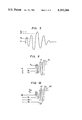
FIGS. 5, 6 and 10 are graphs plotting voltage amplitude in the vertical axis versus time in the horizontal axis showing ultrasonic pulses;
FIG. 7 is a timing diagram showing the operation of the apparatus of FIG. 1;
FIGS. 8 and 9 are graphs plotting voltage amplitude in the vertical axis versus time in the horizontal axis showing the attenuation of the ultrasonic pulse produced by bubbles;
FIG. 11 is a block diagram showing the ultrasonic acoustical flow rate or flow speed measuring apparatus of the present invention;
FIG. 12 is a circuit diagram showing stage 40 of FIG. 11 in greater detail;
FIG. 13 is a circuit diagram showing state 41 of FIG. 11 in greater detail;
FIG. 14 is a timing diagram showing the output waveform at various nodes in the circuit of FIG. 13; and
FIG. 15 is a third diagram showing stage 42 of FIG. 11 in greater detail.
A conventional ultrasonic flow meter discussed above and disclosed in Japanese Patent Application (OPI) 130261/1974 is shown in block diagram form in FIG. 1. Reference numeral 10 designates a measuring region or pipe used to measure the flow speed or flow rate of a fluid flowing therethrough in the direction of the arrow. Ultrasonic transducers 13 and 14 are mounted along the outer wall of measuring pipe 10 by mounting elements 15 and 16, respectively. Each of the transducers 13, 14 is capable of transforming an electrical signal into a corresponding acoustical signal and is capable of transforming a received acoustical signal into a corresponding electrical signal. In a first mode, for example, transducer 13 serves as an acoustical transmitting unit while transducer 14 serves as an acoustical receiving unit. In a second mode, for example, transducer 13 serves as an acoustical unit while transducer 14 serves as an acoustical transmitting unit. A mode switching unit 9 permits alternate switching between the two modes of operation of transducers 13 and 14 by providing mode switching signals A and B to a gate circuit 6.
A counter 3 operates to count the output signal provided by one of the oscillators 11 or 12 of the oscillator element 1. The counting operation of counter 3 is started in response to the output signal provided by synchronizing pulse generating circuit 2. When the count value of counter 3 reaches a value N, which is preselected in accordance to parameters such as the inside diameter of the measuring pipe 10 and the like, counter 3 outputs a counting operation finish signal to a delay element 4, which, in turn, outputs an output signal V in a predetermined period of time thereafter. The output signal V is applied to the time difference detection circuit 8.
The abnormally monitoring circuit 31 monitors whether an ultrasonic acoustical wave has been sonically absorbed by the fluid whose flow rate or flow speed is being measured. The abnormality monitoring circuit 31 includes an abnormality monitoring comparison circuit 19 to which an abnormality monitoring voltage EI is applied as well as the output signal H, a flip-flop 22 which provides an output signal X according to the output signal from comparison circuit 19 and is reset whenever each measuring period is ended, a sampling pulse generating circuit 25 which provides a sampling pulse U for controlling the timing when the output signal S of the time difference detection circuit 8 is applied to oscillator stage 1, and NAND circuit 26 to which the output signal X from flip-flop 22 and the sampling pulse U from sampling pulse generator circuit 25 are applied. The abnormality monitoring voltage E1, the amplitude monitoring voltage E2 and the set voltage E3 are set to the voltage levels of, for example, 2.5 V, 3 V and 1.5 V, respectively.
When the output signal H of the amplifier 7 exceeds the set voltage E3 of the trigger circuit 30, as shown in the wave form plot of FIG. 5, the trigger circuit 30 outputs the trigger signal Z. It should be noted that the voltage level of the set voltage E3 is selected such that the arrival of the first half cycle in the wave form signal H can be detected. If the output signal H of amplifier 7 exceeds the abnormality monitoring voltage E1, flip-flop 22 is caused to change state and the output signal X is continuously outputted causing the NAND circuit 26 to provide the output signal W. When the sampling pulse U is provided, however, output signal W is no longer provided by NAND circuit 26.
The time difference detection circuit 8 is illustrated in detail in FIG. 3. At the input side of circuit 8, there is provided a NAND circuit 100 to which the trigger signal Z of the trigger circuit 30 and the output signal V of the delay element 4 are applied. When the trigger signal V coincides with the output signal V and, thus, the output signal M of the NAND circuit 100 is no longer provided, a transistor Q1 is driven to the nonconductive or OFF state. Because transistor Q1 is now in the OFF state, a charging current from a constant current circuit 90 flows into a capacitor C through a diode D and charges the capacitor C.
Constant current circuit 90, diode D and capacitor C form a ramp circuit. The output signal R of the ramp circuit, which is the charged voltage level of the capacitor C, is applied to the positive input of a differential amplifier 80. A propagation time measuring set voltage E50 is applied to the negative input of the differential amplifier 80. The difference voltage between set voltage E50 and the output signal R of the ramp circuit is provided by the time difference detection circuit 8 as an output signal 5. The set voltage E50 is approximately 5 V. A field-effect transistor Q4 functions to discharge the capacitor C, and its ON-OFF operation is controlled by a signal K.
The output S of the time difference detection circuit 8 is applied to an oscillator control circuit 32 which controls the operation of the oscillator stage 1.
The operation of the conventional ultrasonic flow rate measuring device shown in FIG. 1 is now described with reference to FIG. 7. First, for purposes of explanation, it is assumed that transducer 14 is acting as the ultrasonic acoustical receiving unit due to mode switching signal A from mode switching unit 9, that oscillator 11 in oscillator stage 1 is providing its output to synchronizing pulse generating circuit 2 and to counter 3, and that gate circuit 6 is providing the output signal from pulse generator 5 to transmitting transducer 13 and is providing the electrical analog of the ultrasonic acoustical signal received by transducer 14 to amplifier 7. In this case, when delay element 4 provides its output signal V after the lapse of a predetermined time period, the output signal M from MAND 100 is no longer provided. This causes the charging of capacitor C in the ramp circuit to be started (see FIGS. 2 and 7). Thereafter, when the output signal H from amplifier 7, which corresponds to the output signal from receiving transducer 14, exceeds set voltage E3 of trigger circuit 30, output signal Z from trigger circuit 30 is no longer provided, causing NAND circuit 100 to provide output signal M, which turns transistor Q1 on and stops the charging of the capacitor C in the ramp circuit.
In the present operation example it is assumed that the value of the output signal R of the ramp circuit is represented by R1. The output signal R1 is compared by comparator 80 with set voltage E50, and the difference voltage ε therebetween is provided as the output signal S of the time difference detection circuit 8. The oscillation frequency of oscillator 11 is controlled in accordance with the difference voltage ε. It should be noted that the control of the oscillation frequency is effected so that the difference voltage ε is reduced to zero, that is, the output voltage R1 becomes equal to the set voltage E50. Thus, a forward direction propagation time Ta, as shown in FIG. 6, obtained when an ultrasonic pulse is emitted in a forward direction with respect to the flow of the fluid whose flow rate is being measured is used to set the oscillation frequency of oscillator 11. Thereafter, the measuring period to determine the forward direction propagation time Ta is completed.
Next, because of the presence of mode switching signal B from mode switching circuit 9, transducer 14 is connected to serve as the transmitting unit while transducer 13 is connected to serve as the receiving unit, the output from oscillator 12 of oscillator stage 1 is provided to the synchronizing pulse generating circuit 2 and to the counter 3, and the gate circuit 6 is controlled such that the output signal from the pulse generating circuit 5 is applied to transmitting transducer 14 and the electrical analog of the ultrasonic acoustical signal received by transducer 13 is provided to amplifier 7. In a manner similar to the above-described case, a reverse direction propagation time Tb, as shown in FIG. 6, obtained when an ultrasonic pulse is emitted in a reverse direction with respect to the flow of the fluid whose flow rate is being measured is used to set the oscillation frequency of the oscillator 12. Thereafter, the measuring period to determine the reverse direction propagation time Tb is ended.
The difference between the oscillation frequencies of the oscillators 11 and 12 is picked up by a reversible counter 17 as a frequency difference proportional to the flow speed. A difference signal is provided by counter 17 to a display circuit 18, which displays the difference signal as the flow rate or flow speed of the fluid being measured. It should be noted that in FIG. 6, the signal H1 is a waveform obtained when an ultrasonic pulse is emitted in the forward direction with respect to the flow of a fluid being measured, and the signal H2 is a waveform obtained when an ultrasonic pulse is emitted in the reverse direction.
Sometimes, a fluid whose flow rate is to be measured is pumped from a reservoir through a measuring pipe, and the pumping introduces bubbles into fluid.
The inventors have performed many experiments relating to the effect of bubbles on the accuracy of the measured fluid flow rate or flow speed. It has been discovered that the ultrasonic pulse emitted by the transmitting transducer 13 or 14 is greatly attenuated by the bubbles, and that the attenuation is not uniform from one emitted pulse to the next. Specifically, it has been discovered that when an ultrasonic signal whose third cycle f3 is higher in peak value than the fourth cycle f4 is emitted by the transmitting transducer, as shown in part (A) of FIG. 8, the receiving transducer receives an ultrasonic signal whose third cycle f3 ' is lower in peak value than the fourth wave f4 ', as shown in part (B) of FIG. 8. If this received ultrasonic signal is amplified by amplifier 7, then output signal waveform from amplifier 7 is as indicated in the part (C) of FIG. 8. With respect to waveform (C), amplification by amplifier 7 is performed so that the maximum point of cycle f4 " is of a preselected amplitude, such as E2, and cycles f.sub. 1 " and f2 " and f3 " are amplified in accordance therewith.
However, in the extreme case the following phenomena have been observed. On the transmission side, the fourth cycle f4 is lower in peak value than the third cycle f3, and the fifth cycle f5 is lower in peak value than the fourth cycle f4. This is shown in part (A) of FIG. 9. On the receiving side, the fourth cycle f4 ' is higher in peak value than the third cycle f3 ', and the fifth cycle f5 ' is higher in peak value than the fourth cycle f4 '. This is shown in part (B) of FIG. 8. The inventors attribute this phenomena to the fact that the ultrasonic signal is greatly absorbed by the bubbles at the frequency discontinuity point.
Accordingly, as indicated in FIG. 10, the arrival of the output signal H1 ' from amplifier 7 obtained when the ultrasonic signal is emitted in the forward direction with respect to the flow of the fluid to be measured can be detected from the first wave by the trigger circuit 30. However, with respect to the output signal H2 ' from amplifier 7 obtained when the ultrasonic signal is emitted in the reverse direction with respect to the flow of the fluid to be measured, because of the excessive sonic absorbed by the bubbles, which causes the first cycle f1 " to be greatly attenuated, the arrival of the output signal H2 ' is detected due to second cycle f2 " by the trigger circuit 30 even if the maximum peaks of cycles f4 " and f5 " are made to have the amplitude value of E2. This produces a measurement error corresponding to a period of time of ΔT', as shown in FIG. 10.
Thus, in the case where the first cycle output signal H from amplifier 7 does not exceed the set voltage but the second cycle does exceed the set voltage, as indicated in FIG. 7, suspension of output signal Z from trigger circuit 30 is delayed as much as a time T2, which corresponds to the delay time ΔT' of FIG. 10. Thus, capacitor C in the ramp circuit is excessively charged as much as the delay time T2. In such a case, the value R2 of the output signal R of the ramp circuit is compared with the set value E50, causing the measured result to indicate a flow speed higher than the actual flow speed. More specifically, the delay time ΔT' of the second cycle when compared with the first cycle in the output signal H of amplifier 7 is about 1 μsec in the case when the ultrasonic frequency is 1 MHz. If, in this connection, the slope of the ramp of the output signal R is 2.5 V/μsec, then the value R2 is about 7.5 V. If the ultrasonic frequency is 0.5 MHz, then the delay time T' is about 2 μsec, causing the value R2 to be about 10 V.
The two values of R2, i.e., 7.5 V or 10 V, are compared with the set voltage E50, which is 5 V. Accordingly, if the oscillation frequencies of oscillators 11 and 12 are controlled so that the difference signal ε0 therebetween the output signal S of time difference detection circuit 8 is brought to zeroed, then the measurement result exhibits a substantial error.
In the description of operation given above, it has been stated that FIG. 7 shows the output waveforms of various circuits obtained when the ultrasonic pulse is emitted in the forward direction with respect to the flow of the fluid to be measured. However, because forward direction case and the reverse direction case can be described in the same manner, FIG. 7 is employed for a description of the operation in the case of reverse direction.
In the situation where the device is designed to detect the arrival of the ultrasonic pulse by sensing the second cycle, if the peak value of the first wave becomes excessively high, detection of the ultrasonic pulse arrival is shifted to the first cycle, causing the measured to include an error. For instance, in such a case, the output signal R is about 2.5 V when the ultrasonic frequency 1 MHz, and is about 0 V when the ultrasonic frequency 0.5 MHz.
The present invention eliminates the false detection deficiency present in the conventional ultrasonic flow rate or flow speed measuring device as described above by providing an ultrasonic flow speed or flow rate measuring device which produces an automatic time compensation for the shift in detection of the arrival of an ultrasonic pulse when detection is caused by the preceding or following cycle and is not caused by the proper cycle.
The present invention provides the automatic compensation by adding the following circuits having the stated functions. An abnormality monitoring circuit having an abnormality monitoring voltage. When a signal corresponding to the output signal of the receiving transducer exceeds the abnormality monitoring voltage, an output signal is produced. A trigger circuit having at least two set voltage, a first set voltage and a second set voltage. The first set voltage is supplied as a set value for the normal condition. When a signal corresponding to the output signal of the receiving transducer exceeds the first set voltage, an output signal is applied to the time difference circuit. A mistrigger detection circuit having at least one set voltage. When a signal relating to the output signal of the time difference detection circuit exceeds the set voltage, an output signal is produced in accordance with the output signal of the abnormality monitoring circuit, so that the set voltage of the trigger circuit is changed to the second set voltage in accordance with the output signal of the mistrigger detection circuit.
One preferred embodiment of the present invention is now described with reference to FIG. 11. It should be noted that corresponding components between FIGS. 1 and 11 have the same reference numbers.
In a manner similarly to the circuit shown in FIG. 1, the output signal of amplifier 7 is applied to the amplitude monitoring circuit 29, a trigger circuit 40, and the abnormality monitoring circuit 31. In this case, the trigger circuit 40 is so designed that, as shown in FIG. 12, for instance, two set voltages E3 and E30 are supplied thereto. For example, when a transistor Q2 is in the conductive or ON state, the set voltage E3 is applied to a comparison circuit 21 through resistors R1 and R2 by an electric source E300, and when the transistor Q2 is in the non-conductive or OFF state, the set voltage E30 is applied to the comparison circuit 21 by means of the voltage divider of resistors R1, R2, R3 and R4 connected in series to electric source E300. The set voltage E30 is 2.0 V in this embodiment.
The state of transistor Q2 is controlled via a resistor R5, and transistor Q2 is normally maintained in the conductive or ON state.
A mistrigger detection circuit 41 is provided in order to determine which received cycle has been detected in the case when the ultrasonic pulse is substantially attenuated. The mistrigger detection circuit 41, as shown in FIG. 13, includes comparison circuits 431 and 432, and an R-S flip-flop 44. Set voltage E61 and E62 are provided to comparison circuits 431 and 432, respectively, by means of resistors R9, R10 and R11 and an electric source E6. Set voltage E61 and E62 have values of about 6 V and 4 V, respectively. The value of set voltage E61 is determined by taking into account the fact that if the second cycle is employed as the detecting cycle and the ultrasonic frequency is 1 MHz, then the output signal R of the ramp circuit is about 7 V. On the other hand, the value for set voltage E62 is determined by taking into account the fact that in the case where the original detecting cycle is the second cycle, the output signal R of the ramp circuit is about 2.5 V in the same manner as above.
In the present embodiment, the circuitry is designed so that the first cycle is the cycle from which detection should be made. It should be also noted that the output signal R from the ramp circuit is applied to the remaining input terminals of the comparison circuits 431 and 432.
When the output signal R exceeds set voltage E61, comparison circuit 431 outputs continuosly an ON or "1" signal, while comparison circuit 432 outputs continuously an OFF or "0" signal. The R-S flip-flop circuit 44 comprises NAND circuits 441, 442, 443 and 444, and a NOT circuit 445. The output signal W of the abnormality monitoring circuit 31 is applied to the input of NOT circuit 445. The output signal F of the mistrigger detection circuit 41 is provided as the output of NAND circuit 443.
The output signal F is normally at a logical level "1" so as to maintain the transistor Q2 in the conductive or ON state, as shown in FIG. 12. FIG. 14 is a waveform diagram showing the outputs of various elements. More specifically, part (A) of FIG. 14 shows waveforms obtained for the case where an ultrasonic pulse is normally detected, or the arrival thereof is detected from the first cycle. Part (B), on the other hand, shows waveforms obtained in the case where an ultrasonic pulse is abnormality detected, or the arrival thereof is detected from the second cycle. As is apparent from part (A) of FIG. 14, in the case where detection of the ultrasonic pulse is normal, the output signal F of the mistrigger detection circuit 41 is maintained unchanged, that is, the signal is maintained in the high or "1" state. On the other hand, as is clear from part (B) of FIG. 14, in the case where detection of the ultrasonic pulse is abnormal, the output signal F of the mistrigger detection circuit 41 is changed to the low or "0" state when the output signal of the abnormality monitoring circuit 31 is provided. This state is maintained unchanged until absorption of the ultrasonic pulse by the fluid flow being measured again returns to the normal condition, as described above. When the output signal F of the mistrigger detection circuit 41 goes to the low or "0" state, transistor Q2 of trigger circuit 40 goes to the non-conductive or OFF state, causing the set voltage E30 to be provided to the negative input of comparison circuit 21.
When the set voltage of the trigger circuit 40 is changed to the E30 value, as is shown in FIG. 7, the next ultrasonic pulse detection is caused by the second cycle, and not by the first cycle which is detected in the normal case.
If detection of the ultrasonic pulse arrival is shifted from the first cycle to the second cycle, the ultrasonic propagation time is increased by as much as the shifting time, for instance, the amount ΔT', as shown in FIG. 7. The effect of this shifting time is present in both the forward direction and reverse direction cases. Thus, if it is possible to subtract out the shifting time ΔT' from the forward direction ultrasonic propagation time and the reverse direction ultrasonic propagation time, then the shifting time problem is eliminated. However, in this embodiment of the present invention, the ultrasonic propagation time is used to control the frequency of the oscillator 11 of 12, and, therefore, the propagation time is employed as the denominator. Thus, it is impossible to completely cancel the shifting time ΔT' in the present embodiment, and the measured result necessary involves some error, albeit a small one.
In view of the above description, the present invention provides a method of compensating for the shifting time ΔT' so as to improve measurement accuracy.
More specifically, as shown in FIG. 11, a delay compensation circuit 42 is provided between the counter 3 and the delay element 4 so that when the detection of the ultrasonic pulse arrival is shifted from the first cycle to the second cycle, the outputting of output signal V from delay element 4 is delayed.
The delay compensation circuit 42, as shown in FIG. 15, includes a mono-stable multivibrator 45, a gate circuit 46 and a NOT circuit 17. The gate circuit 46 includes AND circuits 641 and 642, and an OR circuit 463. The output signal F of mistrigger detection circuit 41 is applied to the AND circuit 641 and to the NOT circuit 47.
When the output signal F of the mistrigger detection circuit 41 goes to the low or "0" state, in the next measurement, the output signal provided by counter 3 to delay element 4 is delayed as much as the output generation time T1 of the mono-stable multivibrator 45, as shown by the plots for V and R in FIG. 7. Accordingly, generation of the output signal V of the delay element 4 is delayed as much as the time period T1. The time period T1 is selected so as to be substantially equal to the shifting time ΔT' required for the ultrasonic pulse arrival detection to shift from the first cycle to the second cycle.
Thus, as is indicated in FIG. 7, shifting time ΔT' can be compensated for by delaying by an amount of time T1 the time instant when the charging of capacitor C in the ramp circuit of FIG. 3 is started. Reference character M' in FIG. 7 designates the output signal provided the NAND circuit 100 (FIG. 3) when compensation for shifting time ΔT' is being provided.
As is apparent from the above description, according to the present invention, the mistrigger detection circuit 41 detects when detection of the ultrasonic pulse arrival has shifted from the original detecting cycle to the preceding or following cycle, with the aid of the outut signal W from the abnormality monitoring circuit 31 adapted to monitor whether the ultrasonic pulse is normal, and with the aid of signal R relating to the output signal S of the time difference detection circuit 8. The set voltage of the trigger circuit 40, which is adapted to detect the ultrasonic pulse arrival so as to control the time difference detection circuit 8, is changed in accordance with the output signal F of the mistrigger detection circuit 41. As a result, the ultrasonic pulse arrival detecting wave is changed from the original detecting cycle to the preceding or following cycle in the succeeding measurement, and this cycle is then utilized to detect the ultrasonic wave arrival in both of the forward and reverse directions. Therefore, the measurement accuracy is improved. In addition, the delay compensation circuit 42 is provided according to the present invention so that the rise of the output signal V of the delay element 4, which is applied to the time difference detection circuit 8, is delayed substantially as much as the shifting time 1/T' of the detecting wave, whereby the measurement accuracy is further improved.
In the above-described embodiment of the present invention, on the basis of the output signal F of the mistrigger detection circuit 41, the set voltage of the trigger circuit 40 is automatically changed to the set voltage E30 in response to the ON-OFF operation of the transistor Q2. However, it should be noted that the set voltage may also be changed to the set voltage E30 as follows. A lamp is provided which is turned on and off by the output signal F of the mistrigger circuit 41. A manual switch is connected in parallel with resistors R3 and R4 instead of the transistor Q2. The set voltage change can be effected by operating the manual switch in accordance with the ON-OFF operation of the lamp.
Claims (2)
1. In an ultrasonic flow rate measuring device of the type having a pair of transducers disposed oppositely on a pipe through which a fluid to be measured flows and controlled alternately to be in a transmitting mode in which an electric signal is converted into an acoustical signal and a receiving mode in which a received acoustical signal is converted into an electrical signal, an electrical pulse generating circuit for exciting the one of said transducers which is in the transmitting mode, two oscillation circuits whose oscillation frequencies can be varied, a counter which counts the output signal of each oscillation circuit and provides an output signal when the count value of said counter reaches a predetermined value, a delay element for providing a delay time to said output signal of said counter, and a time difference detection circuit responsive to the output signal of said delay element and to the output signal of the one of said transducers in the receiving mode, the improvement comprising:
(a) an abnormality monitoring circuit responsive to a signal H corresponding to the output of said receiving transducer for providing an output signal W when said signal H exceeds an abnormality monitoring voltage E1 ;
(b) a trigger circuit for providing an output signal Z to said time difference detection circuit when said signal H exceeds a set voltage E3 and for providing in response to a signal F said output signal Z to said time difference detection circuit when said signal H exceeds a set voltage E30 ; and
(c) a mistrigger detection circuit for providing said output signal F when said output signal W is present and when a signal R from said time difference circuit exceeds a set voltage E61.
2. The apparatus as recited in claim 1, further comprising a delay compensation circuit for delaying by a predetermined period of time the providing of said output signal from said counter to said delay element, said predetermined period of time being set in accordance with said output signal F of said mistrigger detection circuit.
Applications Claiming Priority (2)
| Application Number | Priority Date | Filing Date | Title |
|---|---|---|---|
| JP52089404A JPS5829854B2 (en) | 1977-07-26 | 1977-07-26 | Ultrasonic measuring device |
| JP52-89404 | 1977-07-26 |
Publications (1)
| Publication Number | Publication Date |
|---|---|
| US4183244A true US4183244A (en) | 1980-01-15 |
Family
ID=13969694
Family Applications (1)
| Application Number | Title | Priority Date | Filing Date |
|---|---|---|---|
| US05/928,322 Expired - Lifetime US4183244A (en) | 1977-07-26 | 1978-07-26 | Ultrasonic flow rate measuring apparatus |
Country Status (4)
| Country | Link |
|---|---|
| US (1) | US4183244A (en) |
| JP (1) | JPS5829854B2 (en) |
| BR (1) | BR7804790A (en) |
| DE (1) | DE2832835C2 (en) |
Cited By (47)
| Publication number | Priority date | Publication date | Assignee | Title |
|---|---|---|---|---|
| US4334431A (en) * | 1978-08-09 | 1982-06-15 | Fuji Electric Company, Ltd. | Ultrasonic measuring instrument |
| US4402231A (en) * | 1981-04-09 | 1983-09-06 | Fischer & Porter Company | AGC Amplifier for ultrasonic measuring system |
| US4417481A (en) * | 1980-05-02 | 1983-11-29 | Erwin Sick Gmbh Optik-Elektronik | Apparatus for measuring the speed of flow of a flowable medium by determining the transit time of sound waves therein |
| US4442719A (en) * | 1982-01-11 | 1984-04-17 | Allen Ollie J | Acoustic flowmeter |
| US4480485A (en) * | 1982-10-01 | 1984-11-06 | Panametrics, Inc. | Acoustic flowmeter with envelope midpoint tracking |
| WO1985000653A1 (en) * | 1983-07-29 | 1985-02-14 | Panametrics, Inc. | Improved intervalometer time measurement apparatus and method |
| US4557148A (en) * | 1983-04-21 | 1985-12-10 | Yokogawa Hokushin Electric Corporation | Ultrasonic flowmeter |
| US4630482A (en) * | 1985-06-17 | 1986-12-23 | John Traina | Method and apparatus for ultrasonic measurements of a medium |
| US4726235A (en) * | 1986-03-12 | 1988-02-23 | Available Energy, Inc. | Ultrasonic instrument to measure the gas velocity and/or the solids loading in a flowing gas stream |
| US4821569A (en) * | 1987-10-30 | 1989-04-18 | Fischer & Porter Co. | Parasitic echo pulse rejector for ultrasonic liquid level meter |
| US4882934A (en) * | 1986-03-12 | 1989-11-28 | Charles B. Leffert | Ultrasonic instrument to measure the gas velocity and/or the solids loading in a flowing gas stream |
| US5277070A (en) * | 1991-08-01 | 1994-01-11 | Xecutek Corporation | Ultrasonic gas flow measurement method and apparatus |
| US5493916A (en) * | 1991-06-25 | 1996-02-27 | Commonwealth Scientific and Industrial Research Organisation--AGL Consultancy Pty Ltd. | Mode suppression in fluid flow measurement |
| US5668326A (en) * | 1996-10-04 | 1997-09-16 | Dieterich Technology Holding Corp. | Method and apparatus for detecting and aligning a signal |
| US5748504A (en) * | 1996-06-12 | 1998-05-05 | Welch Allyn, Inc. | Calibration method for use with ultrasonic flowmeters |
| US5753824A (en) * | 1996-06-12 | 1998-05-19 | Welch Allyn, Inc. | Sampling method and apparatus for use with ultrasonic flowmeters |
| US5777238A (en) * | 1996-06-12 | 1998-07-07 | Welch Allyn, Inc. | Driver-receiver apparatus for use with ultrasonic flowmeters |
| US5814737A (en) * | 1996-10-04 | 1998-09-29 | Dieterich Technology Holding Corp. | Apparatus and method of detecting an ultrasonic signal |
| US5831175A (en) * | 1996-06-12 | 1998-11-03 | Welch Allyn, Inc. | Method and apparatus for correcting temperature variations in ultrasonic flowmeters |
| EP0932029A2 (en) * | 1998-01-15 | 1999-07-28 | Siemens-Elema AB | Acoustic flow meter |
| CN100360908C (en) * | 1994-10-19 | 2008-01-09 | 松下电器产业株式会社 | Flow rate measurement method and ultrasonic flow meter |
| US20130239698A1 (en) * | 2009-08-18 | 2013-09-19 | Rubicon Research Pty Ltd. | Flow Meter Assembly, Gate Assemblies and Methods of Flow Measurement |
| US20140236533A1 (en) * | 2011-10-13 | 2014-08-21 | Jens Drachmann | Ultrasonic Flow Meter |
| US8857269B2 (en) | 2010-08-05 | 2014-10-14 | Hospira, Inc. | Method of varying the flow rate of fluid from a medical pump and hybrid sensor system performing the same |
| CN104428636A (en) * | 2012-02-07 | 2015-03-18 | 关联封闭合资股份公司 | Method for passing signals through a medium under monitoring |
| US20150355001A1 (en) * | 2014-06-10 | 2015-12-10 | Texas Instruments Incorporated | Extended range adc flow meter |
| CN107621292A (en) * | 2017-07-25 | 2018-01-23 | 辽宁航宇星物联仪表科技有限公司 | A kind of ultrasonic water meter mistake ripple compensation method of family |
| US10022498B2 (en) | 2011-12-16 | 2018-07-17 | Icu Medical, Inc. | System for monitoring and delivering medication to a patient and method of using the same to minimize the risks associated with automated therapy |
| US10166328B2 (en) | 2013-05-29 | 2019-01-01 | Icu Medical, Inc. | Infusion system which utilizes one or more sensors and additional information to make an air determination regarding the infusion system |
| US10342917B2 (en) | 2014-02-28 | 2019-07-09 | Icu Medical, Inc. | Infusion system and method which utilizes dual wavelength optical air-in-line detection |
| US10430761B2 (en) | 2011-08-19 | 2019-10-01 | Icu Medical, Inc. | Systems and methods for a graphical interface including a graphical representation of medical data |
| US10463788B2 (en) | 2012-07-31 | 2019-11-05 | Icu Medical, Inc. | Patient care system for critical medications |
| US10578474B2 (en) | 2012-03-30 | 2020-03-03 | Icu Medical, Inc. | Air detection system and method for detecting air in a pump of an infusion system |
| US10596316B2 (en) | 2013-05-29 | 2020-03-24 | Icu Medical, Inc. | Infusion system and method of use which prevents over-saturation of an analog-to-digital converter |
| US10605779B2 (en) | 2015-02-16 | 2020-03-31 | Sensaction Ag | Method for determining properties of a medium and device for determining properties of a medium |
| US10635784B2 (en) | 2007-12-18 | 2020-04-28 | Icu Medical, Inc. | User interface improvements for medical devices |
| US10656894B2 (en) | 2017-12-27 | 2020-05-19 | Icu Medical, Inc. | Synchronized display of screen content on networked devices |
| US10850024B2 (en) | 2015-03-02 | 2020-12-01 | Icu Medical, Inc. | Infusion system, device, and method having advanced infusion features |
| US10874793B2 (en) | 2013-05-24 | 2020-12-29 | Icu Medical, Inc. | Multi-sensor infusion system for detecting air or an occlusion in the infusion system |
| US11135360B1 (en) | 2020-12-07 | 2021-10-05 | Icu Medical, Inc. | Concurrent infusion with common line auto flush |
| US11246985B2 (en) | 2016-05-13 | 2022-02-15 | Icu Medical, Inc. | Infusion pump system and method with common line auto flush |
| US11278671B2 (en) | 2019-12-04 | 2022-03-22 | Icu Medical, Inc. | Infusion pump with safety sequence keypad |
| US11324888B2 (en) | 2016-06-10 | 2022-05-10 | Icu Medical, Inc. | Acoustic flow sensor for continuous medication flow measurements and feedback control of infusion |
| US11344668B2 (en) | 2014-12-19 | 2022-05-31 | Icu Medical, Inc. | Infusion system with concurrent TPN/insulin infusion |
| US11344673B2 (en) | 2014-05-29 | 2022-05-31 | Icu Medical, Inc. | Infusion system and pump with configurable closed loop delivery rate catch-up |
| US11883361B2 (en) | 2020-07-21 | 2024-01-30 | Icu Medical, Inc. | Fluid transfer devices and methods of use |
| US11972395B2 (en) | 2023-02-01 | 2024-04-30 | Icu Medical, Inc. | Systems and methods for a graphical interface including a graphical representation of medical data |
Families Citing this family (4)
| Publication number | Priority date | Publication date | Assignee | Title |
|---|---|---|---|---|
| NL7903822A (en) * | 1978-05-16 | 1979-11-20 | Fuji Electric Co Ltd | ULTRASONIC MEASUREMENT DEVICE. |
| US4271708A (en) * | 1978-05-16 | 1981-06-09 | Fuji Electric Co., Ltd. | Ultrasonic measuring apparatus |
| JPS54149670A (en) * | 1978-05-16 | 1979-11-24 | Fuji Electric Co Ltd | Circuit device for detecting ultrasonic wave propagating time |
| JPS59166814A (en) * | 1983-03-11 | 1984-09-20 | Power Reactor & Nuclear Fuel Dev Corp | Ultrasonic flow meter |
Citations (3)
| Publication number | Priority date | Publication date | Assignee | Title |
|---|---|---|---|---|
| US3818757A (en) * | 1972-05-05 | 1974-06-25 | Saratoga Sys Inc | Dual path ultrasonic fluid flow metering system and method |
| US3869915A (en) * | 1973-01-23 | 1975-03-11 | Joseph Baumoel | Digital flowmeter |
| US4028938A (en) * | 1976-01-26 | 1977-06-14 | Ocean Research Equipment, Inc. | Acoustical flow meter |
-
1977
- 1977-07-26 JP JP52089404A patent/JPS5829854B2/en not_active Expired
-
1978
- 1978-07-25 BR BR7804790A patent/BR7804790A/en unknown
- 1978-07-26 US US05/928,322 patent/US4183244A/en not_active Expired - Lifetime
- 1978-07-26 DE DE2832835A patent/DE2832835C2/en not_active Expired
Patent Citations (3)
| Publication number | Priority date | Publication date | Assignee | Title |
|---|---|---|---|---|
| US3818757A (en) * | 1972-05-05 | 1974-06-25 | Saratoga Sys Inc | Dual path ultrasonic fluid flow metering system and method |
| US3869915A (en) * | 1973-01-23 | 1975-03-11 | Joseph Baumoel | Digital flowmeter |
| US4028938A (en) * | 1976-01-26 | 1977-06-14 | Ocean Research Equipment, Inc. | Acoustical flow meter |
Cited By (72)
| Publication number | Priority date | Publication date | Assignee | Title |
|---|---|---|---|---|
| US4334431A (en) * | 1978-08-09 | 1982-06-15 | Fuji Electric Company, Ltd. | Ultrasonic measuring instrument |
| US4417481A (en) * | 1980-05-02 | 1983-11-29 | Erwin Sick Gmbh Optik-Elektronik | Apparatus for measuring the speed of flow of a flowable medium by determining the transit time of sound waves therein |
| US4402231A (en) * | 1981-04-09 | 1983-09-06 | Fischer & Porter Company | AGC Amplifier for ultrasonic measuring system |
| US4442719A (en) * | 1982-01-11 | 1984-04-17 | Allen Ollie J | Acoustic flowmeter |
| US4480485A (en) * | 1982-10-01 | 1984-11-06 | Panametrics, Inc. | Acoustic flowmeter with envelope midpoint tracking |
| US4557148A (en) * | 1983-04-21 | 1985-12-10 | Yokogawa Hokushin Electric Corporation | Ultrasonic flowmeter |
| US4515021A (en) * | 1983-07-29 | 1985-05-07 | Panametrics, Inc. | Intervalometer time measurement apparatus and method |
| WO1985000653A1 (en) * | 1983-07-29 | 1985-02-14 | Panametrics, Inc. | Improved intervalometer time measurement apparatus and method |
| US4630482A (en) * | 1985-06-17 | 1986-12-23 | John Traina | Method and apparatus for ultrasonic measurements of a medium |
| US4726235A (en) * | 1986-03-12 | 1988-02-23 | Available Energy, Inc. | Ultrasonic instrument to measure the gas velocity and/or the solids loading in a flowing gas stream |
| US4882934A (en) * | 1986-03-12 | 1989-11-28 | Charles B. Leffert | Ultrasonic instrument to measure the gas velocity and/or the solids loading in a flowing gas stream |
| US4821569A (en) * | 1987-10-30 | 1989-04-18 | Fischer & Porter Co. | Parasitic echo pulse rejector for ultrasonic liquid level meter |
| US5493916A (en) * | 1991-06-25 | 1996-02-27 | Commonwealth Scientific and Industrial Research Organisation--AGL Consultancy Pty Ltd. | Mode suppression in fluid flow measurement |
| US5277070A (en) * | 1991-08-01 | 1994-01-11 | Xecutek Corporation | Ultrasonic gas flow measurement method and apparatus |
| CN100360908C (en) * | 1994-10-19 | 2008-01-09 | 松下电器产业株式会社 | Flow rate measurement method and ultrasonic flow meter |
| CN100370232C (en) * | 1994-10-19 | 2008-02-20 | 松下电器产业株式会社 | Flow rate measurement method and ultrasonic flow meter |
| US5748504A (en) * | 1996-06-12 | 1998-05-05 | Welch Allyn, Inc. | Calibration method for use with ultrasonic flowmeters |
| US5753824A (en) * | 1996-06-12 | 1998-05-19 | Welch Allyn, Inc. | Sampling method and apparatus for use with ultrasonic flowmeters |
| US5777238A (en) * | 1996-06-12 | 1998-07-07 | Welch Allyn, Inc. | Driver-receiver apparatus for use with ultrasonic flowmeters |
| US5831175A (en) * | 1996-06-12 | 1998-11-03 | Welch Allyn, Inc. | Method and apparatus for correcting temperature variations in ultrasonic flowmeters |
| US5668326A (en) * | 1996-10-04 | 1997-09-16 | Dieterich Technology Holding Corp. | Method and apparatus for detecting and aligning a signal |
| US5814737A (en) * | 1996-10-04 | 1998-09-29 | Dieterich Technology Holding Corp. | Apparatus and method of detecting an ultrasonic signal |
| EP0932029A2 (en) * | 1998-01-15 | 1999-07-28 | Siemens-Elema AB | Acoustic flow meter |
| EP0932029A3 (en) * | 1998-01-15 | 1999-09-15 | Siemens-Elema AB | Acoustic flow meter |
| US6098467A (en) * | 1998-01-15 | 2000-08-08 | Siemens Elema Ab | Acoustic flow meter wherein false readings are identified dependent on upstream and downstream acoustic transit times |
| US10635784B2 (en) | 2007-12-18 | 2020-04-28 | Icu Medical, Inc. | User interface improvements for medical devices |
| US9804008B2 (en) | 2009-08-18 | 2017-10-31 | Rubicon Research Pty Ltd. | Flow meter assembly, gate assemblies and methods of flow measurement |
| US8893560B2 (en) * | 2009-08-18 | 2014-11-25 | Rubicon Research Pty Ltd. | Flow meter assembly, gate assemblies and methods of flow measurement |
| US9261390B2 (en) | 2009-08-18 | 2016-02-16 | Rubicon Research Pty Ltd. | Flow meter assembly, gate assemblies and methods of flow measurement |
| US20130239698A1 (en) * | 2009-08-18 | 2013-09-19 | Rubicon Research Pty Ltd. | Flow Meter Assembly, Gate Assemblies and Methods of Flow Measurement |
| US9593972B2 (en) | 2009-08-18 | 2017-03-14 | Rubicon Research Pty Ltd. | Flow meter assembly, gate assemblies and methods of flow measurement |
| US8857269B2 (en) | 2010-08-05 | 2014-10-14 | Hospira, Inc. | Method of varying the flow rate of fluid from a medical pump and hybrid sensor system performing the same |
| US11599854B2 (en) | 2011-08-19 | 2023-03-07 | Icu Medical, Inc. | Systems and methods for a graphical interface including a graphical representation of medical data |
| US11004035B2 (en) | 2011-08-19 | 2021-05-11 | Icu Medical, Inc. | Systems and methods for a graphical interface including a graphical representation of medical data |
| US10430761B2 (en) | 2011-08-19 | 2019-10-01 | Icu Medical, Inc. | Systems and methods for a graphical interface including a graphical representation of medical data |
| US10775212B2 (en) | 2011-10-13 | 2020-09-15 | Apator Miitors Aps | Ultrasonic flow meter |
| US20140236533A1 (en) * | 2011-10-13 | 2014-08-21 | Jens Drachmann | Ultrasonic Flow Meter |
| US10416012B2 (en) * | 2011-10-13 | 2019-09-17 | Apator Miitors Aps | Ultrasonic flow meter |
| US10022498B2 (en) | 2011-12-16 | 2018-07-17 | Icu Medical, Inc. | System for monitoring and delivering medication to a patient and method of using the same to minimize the risks associated with automated therapy |
| US11376361B2 (en) | 2011-12-16 | 2022-07-05 | Icu Medical, Inc. | System for monitoring and delivering medication to a patient and method of using the same to minimize the risks associated with automated therapy |
| RU2585308C2 (en) * | 2012-02-07 | 2016-05-27 | Закрытое Акционерное Общество "Когерент" | Method of transmitting signals through controlled medium |
| CN104428636A (en) * | 2012-02-07 | 2015-03-18 | 关联封闭合资股份公司 | Method for passing signals through a medium under monitoring |
| US9322688B2 (en) * | 2012-02-07 | 2016-04-26 | Yuriy I. Romanov | Method for passing signals through a medium under monitoring |
| US20150139288A1 (en) * | 2012-02-07 | 2015-05-21 | Yuriy I. Romanov | Method for passing signals through a medium under monitoring |
| US11933650B2 (en) | 2012-03-30 | 2024-03-19 | Icu Medical, Inc. | Air detection system and method for detecting air in a pump of an infusion system |
| US10578474B2 (en) | 2012-03-30 | 2020-03-03 | Icu Medical, Inc. | Air detection system and method for detecting air in a pump of an infusion system |
| US11623042B2 (en) | 2012-07-31 | 2023-04-11 | Icu Medical, Inc. | Patient care system for critical medications |
| US10463788B2 (en) | 2012-07-31 | 2019-11-05 | Icu Medical, Inc. | Patient care system for critical medications |
| US10874793B2 (en) | 2013-05-24 | 2020-12-29 | Icu Medical, Inc. | Multi-sensor infusion system for detecting air or an occlusion in the infusion system |
| US11433177B2 (en) | 2013-05-29 | 2022-09-06 | Icu Medical, Inc. | Infusion system which utilizes one or more sensors and additional information to make an air determination regarding the infusion system |
| US11596737B2 (en) | 2013-05-29 | 2023-03-07 | Icu Medical, Inc. | Infusion system and method of use which prevents over-saturation of an analog-to-digital converter |
| US10596316B2 (en) | 2013-05-29 | 2020-03-24 | Icu Medical, Inc. | Infusion system and method of use which prevents over-saturation of an analog-to-digital converter |
| US10166328B2 (en) | 2013-05-29 | 2019-01-01 | Icu Medical, Inc. | Infusion system which utilizes one or more sensors and additional information to make an air determination regarding the infusion system |
| US10342917B2 (en) | 2014-02-28 | 2019-07-09 | Icu Medical, Inc. | Infusion system and method which utilizes dual wavelength optical air-in-line detection |
| US11344673B2 (en) | 2014-05-29 | 2022-05-31 | Icu Medical, Inc. | Infusion system and pump with configurable closed loop delivery rate catch-up |
| US10801868B2 (en) * | 2014-06-10 | 2020-10-13 | Texas Instruments Incorporated | Extended range ADC flow meter |
| US20150355001A1 (en) * | 2014-06-10 | 2015-12-10 | Texas Instruments Incorporated | Extended range adc flow meter |
| US11747181B2 (en) | 2014-06-10 | 2023-09-05 | Texas Instruments Incorporated | Extended range ADC flow meter |
| US11255708B2 (en) * | 2014-06-10 | 2022-02-22 | Texas Instruments Incorporated | Extended range ADC flow meter |
| US11344668B2 (en) | 2014-12-19 | 2022-05-31 | Icu Medical, Inc. | Infusion system with concurrent TPN/insulin infusion |
| US10605779B2 (en) | 2015-02-16 | 2020-03-31 | Sensaction Ag | Method for determining properties of a medium and device for determining properties of a medium |
| US10850024B2 (en) | 2015-03-02 | 2020-12-01 | Icu Medical, Inc. | Infusion system, device, and method having advanced infusion features |
| US11246985B2 (en) | 2016-05-13 | 2022-02-15 | Icu Medical, Inc. | Infusion pump system and method with common line auto flush |
| US11324888B2 (en) | 2016-06-10 | 2022-05-10 | Icu Medical, Inc. | Acoustic flow sensor for continuous medication flow measurements and feedback control of infusion |
| CN107621292A (en) * | 2017-07-25 | 2018-01-23 | 辽宁航宇星物联仪表科技有限公司 | A kind of ultrasonic water meter mistake ripple compensation method of family |
| US11029911B2 (en) | 2017-12-27 | 2021-06-08 | Icu Medical, Inc. | Synchronized display of screen content on networked devices |
| US10656894B2 (en) | 2017-12-27 | 2020-05-19 | Icu Medical, Inc. | Synchronized display of screen content on networked devices |
| US11868161B2 (en) | 2017-12-27 | 2024-01-09 | Icu Medical, Inc. | Synchronized display of screen content on networked devices |
| US11278671B2 (en) | 2019-12-04 | 2022-03-22 | Icu Medical, Inc. | Infusion pump with safety sequence keypad |
| US11883361B2 (en) | 2020-07-21 | 2024-01-30 | Icu Medical, Inc. | Fluid transfer devices and methods of use |
| US11135360B1 (en) | 2020-12-07 | 2021-10-05 | Icu Medical, Inc. | Concurrent infusion with common line auto flush |
| US11972395B2 (en) | 2023-02-01 | 2024-04-30 | Icu Medical, Inc. | Systems and methods for a graphical interface including a graphical representation of medical data |
Also Published As
| Publication number | Publication date |
|---|---|
| JPS5829854B2 (en) | 1983-06-25 |
| JPS5424062A (en) | 1979-02-23 |
| DE2832835A1 (en) | 1979-03-01 |
| DE2832835C2 (en) | 1985-03-28 |
| BR7804790A (en) | 1979-04-17 |
Similar Documents
| Publication | Publication Date | Title |
|---|---|---|
| US4183244A (en) | Ultrasonic flow rate measuring apparatus | |
| US5437178A (en) | Controller for ultrasonic sensors | |
| US5277065A (en) | Detector with ringdown frequency matching | |
| KR920010025B1 (en) | Speed measurement device | |
| US5796009A (en) | Method for measuring in a fluid with the aid of sing-around technique | |
| US4080574A (en) | Apparatus for providing time reference signals | |
| US4307456A (en) | Ultrasonic rangefinder | |
| JPS5856085B2 (en) | Method and device for measuring thickness or depth of abnormal area using ultrasonic pulses | |
| US4271708A (en) | Ultrasonic measuring apparatus | |
| US4417481A (en) | Apparatus for measuring the speed of flow of a flowable medium by determining the transit time of sound waves therein | |
| JPH0921667A (en) | Flow rate measuring apparatus | |
| JPS5914172B2 (en) | Ultrasonic measuring device | |
| JPS57187609A (en) | Measuring device for decrease in wall thickness | |
| US5192933A (en) | Field-adjustable ultrasonic detector | |
| KR820000302B1 (en) | Ultrasonic type measuring device | |
| JPS6042385Y2 (en) | Gate signal generation circuit for ultrasonic measurement equipment | |
| KR820000160B1 (en) | Super sound wave type measuring device | |
| JPS5914171B2 (en) | Ultrasonic measuring device | |
| KR830000921Y1 (en) | Ultrasonic wave time detection circuit device | |
| SU894552A1 (en) | Method of ultrasound speed determination | |
| JPS6118465Y2 (en) | ||
| SU1668936A1 (en) | Device for material ultrasonic check | |
| JPH08220229A (en) | Ultrasonic wave sensor | |
| SU309244A1 (en) | SINGLE-CHANNEL ULTRASONIC FLOWMETER | |
| SU1293494A1 (en) | Device for measuring time of ultrasound propagation |