US4106295A - Air pressure differential energy system - Google Patents
Air pressure differential energy system Download PDFInfo
- Publication number
- US4106295A US4106295A US05/777,342 US77734277A US4106295A US 4106295 A US4106295 A US 4106295A US 77734277 A US77734277 A US 77734277A US 4106295 A US4106295 A US 4106295A
- Authority
- US
- United States
- Prior art keywords
- stack
- air
- heat exchanger
- water
- turbine
- Prior art date
- Legal status (The legal status is an assumption and is not a legal conclusion. Google has not performed a legal analysis and makes no representation as to the accuracy of the status listed.)
- Expired - Lifetime
Links
Images
Classifications
-
- F—MECHANICAL ENGINEERING; LIGHTING; HEATING; WEAPONS; BLASTING
- F02—COMBUSTION ENGINES; HOT-GAS OR COMBUSTION-PRODUCT ENGINE PLANTS
- F02C—GAS-TURBINE PLANTS; AIR INTAKES FOR JET-PROPULSION PLANTS; CONTROLLING FUEL SUPPLY IN AIR-BREATHING JET-PROPULSION PLANTS
- F02C1/00—Gas-turbine plants characterised by the use of hot gases or unheated pressurised gases, as the working fluid
- F02C1/04—Gas-turbine plants characterised by the use of hot gases or unheated pressurised gases, as the working fluid the working fluid being heated indirectly
- F02C1/05—Gas-turbine plants characterised by the use of hot gases or unheated pressurised gases, as the working fluid the working fluid being heated indirectly characterised by the type or source of heat, e.g. using nuclear or solar energy
Definitions
- This invention is in the field of high power electrical energy generation systems, and particularly in the field utilizing air as a medium therein.
- An air pressure differential energy generation system comprises a stack for conduction of air from a high to a loW atmospheric pressure level. Means coupled to and partially within the stack are provided for injecting vapor into the stack to increase the humidity therein.
- the vapor may be water vapor.
- a turbine is provided and coupled to the heat exchanger, which turbine is impelled by the air which is warmed by such exchanger.
- the air within the stack is lighter in weight than the air external to the stack during operative mode of the system.
- An electrical generator is coupled to and driven by the turbine during operative mode of the system.
- a solar water heater is connected to the foregoing mentioned means.
- a solar air heater which is an integral part of the stack is located at the high atmospheric pressure level of the stack.
- a geothermal source may be provided to feed geothermal fluid to the heat exchanger.
- the solar water heater may also feed the heat exchanger.
- a valve which is located intermediate the solar water heater and the heat exchanger provides a measure of control. Also a valve is interposed between the geothermal source and the heat exchanger.
- a water filter is provided attached to the output of the solar water heater. Likewise, a fluid filter is attached to the output of the geothermal source.
- heat insulating material is attached to and circumjacent most of the stack.
- a return pipe one end of which is connected to the stack at its low atmospheric pressure level, with the other end of the pipe being connected to the solar water heater, is used.
- a water collector is therefore used at the low atmospheric pressure level at the top of the stack to which the return pipe is connected for collecting the conserved water.
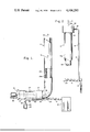
- FIG. 1 is a system schematic structure in elevation and partially in cross section in accordance with the invention.
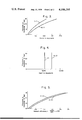
- FIG. 2 shows in elevation and partially in cross section and perspective, a portion of the stack shown in FIG. 1 to which a water collector is attached and a return pipe attached to the water collector to feed back the collected and conserved water to a water source.
- FIG. 3 is an output power graph of the system with respect to elevation levels under several types of operating conditions.
- FIG. 4 is an input power graph of the system with respect to the same elevation levels as in FIG. 3 and the same type of operating conditions.
- FIG. 5 is a percent efficiency graph of the system for the same elevation levels as in FIGS. 3 and 4.
- an air pressure differential energy generating system comprises a stack as provided at 11 for conduction of air 12 from a high atmospheric pressure level at 13 to a low atmospheric pressure level at 14.
- Means 15 are provided within stack 11 for injecting vapor therein.
- vapor may comprise water vapor or the like.
- the vapor mixes with the heated air in the stack and thus retards the adiabatic cooling of such heated air within the stack upon condensation of the vapor occurring intermediate the high and low pressure levels.
- the air within the stack is expanded due to the heating thereof by heat exchanger at 16.
- the air within the stack may be also expanded by virtue of solar energy impinging upon a solar air heater 17 at the high atmospheric pressure end of the stack.
- a solar water heater 18 which contains a supply of water, supplied by source 19, which enables the supply of solar heated water through filter 20 into pipe 21 through valve 22, which valve is opened when geothermal source 23 is not used.
- the solar heated water proceeds in pipe portion 24 for injection into heat exchanger 16.
- Such heated water injected into heat exchanger 16 heats and expands the air forced into the system at 13.
- geothermal source 23 which may be steam, hot water or mineral hot liquids, are by virtue of their own pressures forced through a filter such as at 25 if desired, through valve 26 which is opened when the geothermal source is used and closed when the solar heated water is used.
- a filter such as at 25 if desired
- valve 26 which is opened when the geothermal source is used and closed when the solar heated water is used.
- Such fluid is injected into the heat exchanger to perform a similar function to the function performed by the solar water heating subsystem.
- a turbine is provided at 27 which is shown within the stack or enclosure at the high pressure end of the system, but may be positioned adjacent the heat exchanger. Such turbine 27 is mechanically linked to electrical generator or alternator 28.
- Turbine 27 is impelled by virtue of velocity of the heated air within the system during operative mode of the system.
- the driven generator thus provides the electrical power as indicated in the tables below.
- Enclosure or stack 11 has a metallic pipe portion at 29 of substantial structural strength since stack 11 may be of very large diameter, such as 250 feet.
- Metallic pipe 29 has thermal insulation circumjacent thereto about its length as at 29a.
- the water vapor injected at 15 and later condensed may be reclaimed by means of water collector 30 attached to exit or opening at 14 of enclosure 11.
- the air present in the system will exhaust into the atmosphere at 31 through an extension 30a passing through water collector 30.
- Collector 30 is attached to the exit of stack 11 at 14 so that extension 30a thereof will permit the air to be passed to the atmosphere at 31 while water is being collected in collector 30.
- a port at 32 is provided for connecting thereto a return pipe 33 which connects to solar water heater 18 so as to return the reclaimed water shown flowing at 34 into solar water heater 18, thereby limiting and conserving the quantity of water drawn from water reservoir 19.
- inventive system operates on similar principles and conditions present in tornadoes and waterspouts, wherein hot and humid air at the high atmospheric pressure level escapes to the lower pressure level where relatively dry heavy air causes a natural force action within the system.
- inventive system has conditioned the air as such and provides a vortex for escape of air as well as means for harnessing the generated energy during the air flow within the system.
- Such performance tables resulted from calculations made by a professional engineering consulting firm employed by the inventor, which tables and graphs show the power output, power input to the system and system efficiency, as well as other parameters considered as system concomitants.
- the power levels obtained, the input power needed to obtain such power output levels which input power is obtained from natural sources and therefore substantially free, and the graphical results shown were arrived at by utilizing known physical and mathematical principles which provided the formulations to enable computations to be made by utilizing a Hewlett-Packard Model 2000F digital computer using BASIC language program routines as shown in the reference incorporated document.
- Friction loss was calculated at 34% for the entire system, and is based on data provided at page 5-14 of the Chemical Engineer's Handbook by Robert Perry, published by McGraw-Hill, New York, 5th Edition, 1973.
Abstract
An air pressure differential energy generation system comprises a stack for conduction of air from a high to a low atmospheric pressure level. A vapor injection device within the stack provides a method of filling the stack at least in part with water vapor. A heat exchanger is provided at the high atmospheric pressure end of the stack. A turbine is coupled to the heat exchanger and is impelled by warmed air. An electrical generator is coupled to the turbine to provide electrical power.
Description
A summary of the verified computations made on specification of inventor by Advanced Industrial Development, Inc. of 899 Portola Drive, San Leanardo, California, professional engineering consultants, and entitled Differential Air Pressure Power Generation Engine, concurrently filed, shows the computed performance of the system, and is incorporated by reference as though fully set forth herein.
This invention is in the field of high power electrical energy generation systems, and particularly in the field utilizing air as a medium therein.
It has become obvious to an industrial world that sources of clean energy are rapidly ceasing to meet the needs for high quantity cleanly generated energy. Dependance upon imports for fossil fuels has continued to rise with attendant detriment to the dependent nation. Pollution of air and water have reached a crisis state from use of the fossil fuels, and atomic power does not appear to be keeping up with the power demands. It is with these considerations in mind that the subject invention has been conceived.
U.S. Pat. No. 3,048,006 to Goodman though in the similar field, is simply a chimney stack having a propeller and governor with a heat exchanger to heat the air intake conducted to the heat exchanger by a source type of gas or fluid. No humidity injection means, as needed by a high energy system, is provided by this prior art. No insulation of the tower, as required, is provided. Additionally, this prior art uses a double wall system in which to circulate hot gas therebetween.
U.S. Pat. No. 3,832,853 to Butler though also in similar prior art field, is restrictive to tall buildings. No solar energy to heat air is used. Neither is the air conditioned with humidity to retard adiabadic cooling thereof. The device also does not obtain sufficient height to provide adequate power levels. Additionally, wind energy to drive a fan at the top of his building structure is used, which fan is ineffective where high energy levels are needed to be provided by the energy generation system.
An air pressure differential energy generation system comprises a stack for conduction of air from a high to a loW atmospheric pressure level. Means coupled to and partially within the stack are provided for injecting vapor into the stack to increase the humidity therein. The vapor may be water vapor. A turbine is provided and coupled to the heat exchanger, which turbine is impelled by the air which is warmed by such exchanger. The air within the stack is lighter in weight than the air external to the stack during operative mode of the system.
An electrical generator is coupled to and driven by the turbine during operative mode of the system. A solar water heater is connected to the foregoing mentioned means. A solar air heater which is an integral part of the stack is located at the high atmospheric pressure level of the stack.
A geothermal source may be provided to feed geothermal fluid to the heat exchanger. The solar water heater may also feed the heat exchanger.
A valve which is located intermediate the solar water heater and the heat exchanger provides a measure of control. Also a valve is interposed between the geothermal source and the heat exchanger.
A water filter is provided attached to the output of the solar water heater. Likewise, a fluid filter is attached to the output of the geothermal source.
For effectiveness, heat insulating material is attached to and circumjacent most of the stack.
To conserve water, a return pipe one end of which is connected to the stack at its low atmospheric pressure level, with the other end of the pipe being connected to the solar water heater, is used.
A water collector is therefore used at the low atmospheric pressure level at the top of the stack to which the return pipe is connected for collecting the conserved water.
FIG. 1 is a system schematic structure in elevation and partially in cross section in accordance with the invention.
FIG. 2 shows in elevation and partially in cross section and perspective, a portion of the stack shown in FIG. 1 to which a water collector is attached and a return pipe attached to the water collector to feed back the collected and conserved water to a water source.
FIG. 3 is an output power graph of the system with respect to elevation levels under several types of operating conditions.
FIG. 4 is an input power graph of the system with respect to the same elevation levels as in FIG. 3 and the same type of operating conditions.
FIG. 5 is a percent efficiency graph of the system for the same elevation levels as in FIGS. 3 and 4.
Referring to the figures, an air pressure differential energy generating system comprises a stack as provided at 11 for conduction of air 12 from a high atmospheric pressure level at 13 to a low atmospheric pressure level at 14.
The air within the stack is expanded due to the heating thereof by heat exchanger at 16. Optionally, the air within the stack may be also expanded by virtue of solar energy impinging upon a solar air heater 17 at the high atmospheric pressure end of the stack. Also, such air within the stack may be expanded by virtue of a solar water heater 18 which contains a supply of water, supplied by source 19, which enables the supply of solar heated water through filter 20 into pipe 21 through valve 22, which valve is opened when geothermal source 23 is not used.
The solar heated water proceeds in pipe portion 24 for injection into heat exchanger 16. Such heated water injected into heat exchanger 16 heats and expands the air forced into the system at 13.
The fluid from geothermal source 23, which may be steam, hot water or mineral hot liquids, are by virtue of their own pressures forced through a filter such as at 25 if desired, through valve 26 which is opened when the geothermal source is used and closed when the solar heated water is used. Such fluid is injected into the heat exchanger to perform a similar function to the function performed by the solar water heating subsystem.
From the foregoing, it is obvious that either the solar water heating subsystem or the geothermal system could by suitable valve arrangements, feed means 15 for injecting the requisite amount of vapor or the like.
A turbine is provided at 27 which is shown within the stack or enclosure at the high pressure end of the system, but may be positioned adjacent the heat exchanger. Such turbine 27 is mechanically linked to electrical generator or alternator 28.
Turbine 27 is impelled by virtue of velocity of the heated air within the system during operative mode of the system.
The driven generator thus provides the electrical power as indicated in the tables below.
Enclosure or stack 11 has a metallic pipe portion at 29 of substantial structural strength since stack 11 may be of very large diameter, such as 250 feet. Metallic pipe 29 has thermal insulation circumjacent thereto about its length as at 29a.
If desired, the water vapor injected at 15 and later condensed, may be reclaimed by means of water collector 30 attached to exit or opening at 14 of enclosure 11. The air present in the system will exhaust into the atmosphere at 31 through an extension 30a passing through water collector 30. Collector 30 is attached to the exit of stack 11 at 14 so that extension 30a thereof will permit the air to be passed to the atmosphere at 31 while water is being collected in collector 30.
A port at 32 is provided for connecting thereto a return pipe 33 which connects to solar water heater 18 so as to return the reclaimed water shown flowing at 34 into solar water heater 18, thereby limiting and conserving the quantity of water drawn from water reservoir 19.
It should be noted that the inventive system operates on similar principles and conditions present in tornadoes and waterspouts, wherein hot and humid air at the high atmospheric pressure level escapes to the lower pressure level where relatively dry heavy air causes a natural force action within the system. The inventive system has conditioned the air as such and provides a vortex for escape of air as well as means for harnessing the generated energy during the air flow within the system.
The performance results are shown in two typical cases in tables (1) and (2) below and comparable graphical illustration of same in FIGS. 3, 4 and 5 of the drawings, as were derived by extensive computations that have been incorporated by reference herein.
Such performance tables resulted from calculations made by a professional engineering consulting firm employed by the inventor, which tables and graphs show the power output, power input to the system and system efficiency, as well as other parameters considered as system concomitants. The power levels obtained, the input power needed to obtain such power output levels which input power is obtained from natural sources and therefore substantially free, and the graphical results shown were arrived at by utilizing known physical and mathematical principles which provided the formulations to enable computations to be made by utilizing a Hewlett-Packard Model 2000F digital computer using BASIC language program routines as shown in the reference incorporated document.
In graphing the computer results as a function of elevation of the stack, all output power characteristic curves were shown as a family of curves in FIG. 3, labled (1.1) and (2.1) corresponding to the output power columns below. Similarly, input powers used by the system are graphed in a family for visual comparison in FIG. 4 as (1.2) and (2.2). It is noted that in the illustrated cases the input power was substantially constant with stack elevation level. The percent of output power to input power is graphed in FIG. 5 as (1.3) and (2.3), corresponding to efficiency columns in the tables below.
The atmospheric temperatures as used in the tables were taken from the Handbook of Tables for Applied Engineering Science, by Ray E. Bolz, 1970 edition at page 534, published by CRC Press, Cleveland, Ohio, which shows the US standard atmosphere at 45° north latitude during the month of July.
Friction loss was calculated at 34% for the entire system, and is based on data provided at page 5-14 of the Chemical Engineer's Handbook by Robert Perry, published by McGraw-Hill, New York, 5th Edition, 1973.
__________________________________________________________________________
INITIAL TEMP 83.5     (1.1) (1.2)
                                 (1.3)
ELEV
    STACK
         AMB DIFF
                 LIFT OUTPUT
                            INPUT
                                 EFF
FT  TEMP TEMP
             DEG RATIO
                      MW    MW   %
__________________________________________________________________________
0   83.5 73.5
             10.0
                 0.0187
                      3     5275 0.06
1000
    82.5 70.9
             11.6
                 0.0218
                      7     5275 0.13
2000
    81.4 68.2
             13.2
                 0.0251
                      11    5275 0.20
3000
    80.3 65.4
             14.9
                 0.0284
                      15    5275 0.29
4000
    79.2 62.6
             16.7
                 0.0319
                      21    5275 0.39
5000
    78.1 59.6
             18.4
                 0.0355
                      26    5275 0.50
6000
    76.9 56.6
             20.3
                 0.0392
                      33    5275 0.62
7000
    75.7 53.6
             22.1
                 0.0431
                      40    5275 0.76
                                    (1)
8000
    74.4 50.4
             24.0
                 0.0471
                      48    5275 0.90
9000
    73.1 47.2
             26.0
                 0.0512
                      56    5275 1.06
10000
    71.8 43.8
             28.0
                 0.0555
                      65    5275 1.23
11000
    70.4 40.4
             30.0
                 0.0599
                      75    5275 1.42
12000
    69.0 37.0
             32.0
                 0.0644
                      85    5275 1.62
13000
    67.5 33.4
             34.1
                 0.0690
                      97    5275 1.83
14000
    65.9 29.8
             36.1
                 0.0738
                      109   5275 2.06
15000
    64.3 26.1
             38.2
                 0.0787
                      121   5275 2.30
STACK VELOCITY, FPS = 300
PROPELLOR EFFICIENCY = .7
INITIAL TEMP 93.5     (2.1) (2.2)
                                 (2.3)
ELEV
    STACK
         AMB DIFF
                  LIFT
                      OUTPUT
                            INPUT
                                 EFF
FT  TEMP TEMP
             DEG RATIO
                      MW    MW   %
__________________________________________________________________________
0   93.5 73.5
             20.0
                 0.0375
                      6     7465 0.08
1000
    92.7 70.9
             21.8
                 0.0411
                      13    7465 0.17
2000
    91.9 68.2
             23.7
                 0.0449
                      20    7465 0.27
3000
    91.1 65.4
             25.7
                 0.0488
                      28    7465 0.37
4000
    90.2 62.6
             27.7
                 0.0529
                      36    7465 0.48
5000
    89.4 59.6
             29.7
                 0.0572
                      45    7465 0.61
                                    (2)
6000
    88.5 56.6
             31.9
                 0.0617
                      55    7465 0.74
7000
    87.6 53.6
             34.1
                 0.0663
                      66    7465 0.88
8000
    86.7 50.4
             36.3
                 0.0711
                      77    7465 1.03
9000
    85.8 47.2
             38.6
                 0.0761
                      89    7465 1.20
10000
    84.8 43.8
             41.0
                 0.0813
                      103   7465 1.37
11000
    83.9 40.4
             43.4
                 0.0868
                      116   7465 1.56
12000
    82.9 37.0
             45.9
                 0.0924
                      131   7465 1.76
13000
    81.9 33.4
             48.5
                 0.0982
                      147   7465 1.97
14000
    80.9 29.8
             51.1
                 0.1043
                      164   7465 2.19
15000
    79.8 26.1
             53.7
                 0.1105
                      181   7465 2.43
STACK VELOCITY, FPS = 300
PROPELLOR EFFICIENCY = .7
__________________________________________________________________________
Claims (7)
1. An energy-generating system comprising:
a stack having open lower and upper ends for receipt and discharge respectively of air at relatively high and low atmospheric pressures;
means heating and humidifying the air within said stack adjacent said lower end inducing an upward flow of air in said stack; and
a turbine mounted in said stack and driven by said air flow.
2. The structure of claim 1, said means comprising a heat exchanger and a solar heater connected thereto.
3. The structure of claim 1, said means comprising a heat exchanger and means conducting geothermal fluid thereto.
4. The structure of claim 1, and water collection means adjacent said upper end for recovery of condensate from air discharged thereat.
5. The invention as stated in claim 1, including heat insulating material attached to and circumjacent at least a portion of the stack.
6. The method of generating energy comprising:
heating and humidifying air within and at the lower end of a stack to induce an upward flow of air therein; and
coupling a turbine impeller to said air flow.
7. The method of claim 6, and recovering the condensate in the air at the upper discharge end of said stack.
Priority Applications (1)
| Application Number | Priority Date | Filing Date | Title |
|---|---|---|---|
| US05/777,342 US4106295A (en) | 1977-03-14 | 1977-03-14 | Air pressure differential energy system |
Applications Claiming Priority (1)
| Application Number | Priority Date | Filing Date | Title |
|---|---|---|---|
| US05/777,342 US4106295A (en) | 1977-03-14 | 1977-03-14 | Air pressure differential energy system |
Publications (1)
| Publication Number | Publication Date |
|---|---|
| US4106295A true US4106295A (en) | 1978-08-15 |
Family
ID=25109982
Family Applications (1)
| Application Number | Title | Priority Date | Filing Date |
|---|---|---|---|
| US05/777,342 Expired - Lifetime US4106295A (en) | 1977-03-14 | 1977-03-14 | Air pressure differential energy system |
Country Status (1)
| Country | Link |
|---|---|
| US (1) | US4106295A (en) |
Cited By (23)
| Publication number | Priority date | Publication date | Assignee | Title |
|---|---|---|---|---|
| JPS5675979A (en) * | 1979-11-26 | 1981-06-23 | Assaf Gad | Pumping up method for generating power* power generating method and its device |
| US4373339A (en) * | 1979-04-02 | 1983-02-15 | Trade Finance International | Thermal energy conversion system and method utilizing unencased expandites |
| US4382365A (en) * | 1980-06-04 | 1983-05-10 | Gene Sadao Kira | Energy conversion derived from pressure and temperature differentials at different elevations |
| US4391099A (en) * | 1980-09-22 | 1983-07-05 | Sorensen Jens Ole | Atmospheric thermal energy conversion utilizing inflatable pressurized rising conduit |
| US4453383A (en) * | 1981-07-27 | 1984-06-12 | Collins Wayne H | Apparatus for and method of utilizing solar energy |
| US4475342A (en) * | 1979-11-26 | 1984-10-09 | Lucien Y. Bronicki | Method and means for lifting water and generating power therefrom |
| JPS61247879A (en) * | 1985-04-25 | 1986-11-05 | Agency Of Ind Science & Technol | Atmospheric heat generating system |
| US4742682A (en) * | 1982-02-18 | 1988-05-10 | Geophysical Engineering Co. | Energy-saving, direct-contact, parallel-flow heat exchanger |
| US4878349A (en) * | 1988-12-13 | 1989-11-07 | Julius Czaja | Atmospheric latent heat engine |
| US5095705A (en) * | 1991-04-12 | 1992-03-17 | Oliver Daly | Process for producing energy from water flowing down a borehole and recovery same |
| US6510687B1 (en) | 1996-06-14 | 2003-01-28 | Sharav Sluices Ltd. | Renewable resource hydro/aero-power generation plant and method of generating hydro/aero-power |
| EP1589221A2 (en) * | 2004-04-19 | 2005-10-26 | COMANDU' Angelo | Wind turbine using chimney effect. |
| WO2007118282A1 (en) * | 2006-04-19 | 2007-10-25 | Noel Geoffrey Barton | A heat engine/heat pump |
| US20080178625A1 (en) * | 2007-01-25 | 2008-07-31 | Thompson Christopher E | Method and Apparatus for Harvesting Water and Latent Energy from a Gaseous Mixture |
| WO2009005842A1 (en) * | 2007-07-05 | 2009-01-08 | Jens Ole Sorensen | Solar collector and energy conversion systems and methods |
| WO2009061709A1 (en) * | 2007-11-08 | 2009-05-14 | Mine-Rg, Inc. | Power generation system |
| US20090120090A1 (en) * | 2007-11-08 | 2009-05-14 | Dubois John R | Geothermal power generation system and method for adapting to mine shafts |
| US20090315333A1 (en) * | 2006-03-31 | 2009-12-24 | John Azar | Production of electricity from low-temperature energy sources |
| WO2010074715A1 (en) * | 2008-12-15 | 2010-07-01 | Jens Ole Sorensen | Heated-air conduit for energy conversion systems and methods |
| US20100244455A1 (en) * | 2009-03-30 | 2010-09-30 | Berginc Michael J | Renewable energy electric power generation system derived from mechanical sources |
| US20100313581A1 (en) * | 2007-01-25 | 2010-12-16 | Thompson Christopher E | Method and Apparatus for Harvesting Water and Latent Energy from a Gaseous Mixture |
| US20110100012A1 (en) * | 2009-11-17 | 2011-05-05 | Stallings James R | System and method for transmitting thermal energy |
| US8677752B2 (en) | 2007-11-08 | 2014-03-25 | Mine-Nrg, Inc. | Power generation system |
Citations (6)
| Publication number | Priority date | Publication date | Assignee | Title |
|---|---|---|---|---|
| US3048006A (en) * | 1960-12-27 | 1962-08-07 | Alexander J E Beard | Thermal current driven power generating apparatus |
| US3436908A (en) * | 1967-03-27 | 1969-04-08 | Vukasin Van Delic | Solar air moving system |
| US3720840A (en) * | 1971-10-06 | 1973-03-13 | H Gregg | Wind turbine generator with exhaust gas heater |
| US3894393A (en) * | 1974-05-02 | 1975-07-15 | Lockheed Aircraft Corp | Power generation through controlled convection (aeroelectric power generation) |
| US3936652A (en) * | 1974-03-18 | 1976-02-03 | Levine Steven K | Power system |
| US4033126A (en) * | 1975-04-09 | 1977-07-05 | Newland Elwood L | Solar energy device |
-
1977
- 1977-03-14 US US05/777,342 patent/US4106295A/en not_active Expired - Lifetime
Patent Citations (6)
| Publication number | Priority date | Publication date | Assignee | Title |
|---|---|---|---|---|
| US3048006A (en) * | 1960-12-27 | 1962-08-07 | Alexander J E Beard | Thermal current driven power generating apparatus |
| US3436908A (en) * | 1967-03-27 | 1969-04-08 | Vukasin Van Delic | Solar air moving system |
| US3720840A (en) * | 1971-10-06 | 1973-03-13 | H Gregg | Wind turbine generator with exhaust gas heater |
| US3936652A (en) * | 1974-03-18 | 1976-02-03 | Levine Steven K | Power system |
| US3894393A (en) * | 1974-05-02 | 1975-07-15 | Lockheed Aircraft Corp | Power generation through controlled convection (aeroelectric power generation) |
| US4033126A (en) * | 1975-04-09 | 1977-07-05 | Newland Elwood L | Solar energy device |
Cited By (34)
| Publication number | Priority date | Publication date | Assignee | Title |
|---|---|---|---|---|
| US4373339A (en) * | 1979-04-02 | 1983-02-15 | Trade Finance International | Thermal energy conversion system and method utilizing unencased expandites |
| JPH0211748B2 (en) * | 1979-11-26 | 1990-03-15 | Assaf Gad | |
| US4370859A (en) * | 1979-11-26 | 1983-02-01 | Lucien Y. Bronicki | Method of and means for lifting water and generating power therefrom |
| US4475342A (en) * | 1979-11-26 | 1984-10-09 | Lucien Y. Bronicki | Method and means for lifting water and generating power therefrom |
| JPS5675979A (en) * | 1979-11-26 | 1981-06-23 | Assaf Gad | Pumping up method for generating power* power generating method and its device |
| US4382365A (en) * | 1980-06-04 | 1983-05-10 | Gene Sadao Kira | Energy conversion derived from pressure and temperature differentials at different elevations |
| US4391099A (en) * | 1980-09-22 | 1983-07-05 | Sorensen Jens Ole | Atmospheric thermal energy conversion utilizing inflatable pressurized rising conduit |
| US4453383A (en) * | 1981-07-27 | 1984-06-12 | Collins Wayne H | Apparatus for and method of utilizing solar energy |
| US4742682A (en) * | 1982-02-18 | 1988-05-10 | Geophysical Engineering Co. | Energy-saving, direct-contact, parallel-flow heat exchanger |
| JPS61247879A (en) * | 1985-04-25 | 1986-11-05 | Agency Of Ind Science & Technol | Atmospheric heat generating system |
| US4878349A (en) * | 1988-12-13 | 1989-11-07 | Julius Czaja | Atmospheric latent heat engine |
| US5095705A (en) * | 1991-04-12 | 1992-03-17 | Oliver Daly | Process for producing energy from water flowing down a borehole and recovery same |
| US6510687B1 (en) | 1996-06-14 | 2003-01-28 | Sharav Sluices Ltd. | Renewable resource hydro/aero-power generation plant and method of generating hydro/aero-power |
| US6647717B2 (en) | 1996-06-14 | 2003-11-18 | Sharav Sluices, Ltd. | Renewable resource hydro/aero-power generation plant and method of generating hydro/aero-power |
| EP1589221A2 (en) * | 2004-04-19 | 2005-10-26 | COMANDU' Angelo | Wind turbine using chimney effect. |
| EP1589221A3 (en) * | 2004-04-19 | 2006-07-19 | COMANDU' Angelo | Wind turbine using chimney effect. |
| US20090315333A1 (en) * | 2006-03-31 | 2009-12-24 | John Azar | Production of electricity from low-temperature energy sources |
| WO2007118282A1 (en) * | 2006-04-19 | 2007-10-25 | Noel Geoffrey Barton | A heat engine/heat pump |
| AU2007240126B2 (en) * | 2006-04-19 | 2012-03-01 | Noel Geoffrey Barton | A heat engine/heat pump |
| US7775063B2 (en) | 2007-01-25 | 2010-08-17 | Thompson Christopher E | Method and apparatus for harvesting water and latent energy from a gaseous mixture |
| US20100313581A1 (en) * | 2007-01-25 | 2010-12-16 | Thompson Christopher E | Method and Apparatus for Harvesting Water and Latent Energy from a Gaseous Mixture |
| US20080178625A1 (en) * | 2007-01-25 | 2008-07-31 | Thompson Christopher E | Method and Apparatus for Harvesting Water and Latent Energy from a Gaseous Mixture |
| WO2009005842A1 (en) * | 2007-07-05 | 2009-01-08 | Jens Ole Sorensen | Solar collector and energy conversion systems and methods |
| US20110011087A1 (en) * | 2007-07-05 | 2011-01-20 | Jens Ole Sorensen | Solar collector and energy conversion systems and methods |
| US7984613B2 (en) | 2007-11-08 | 2011-07-26 | Mine-Rg, Inc. | Geothermal power generation system and method for adapting to mine shafts |
| US7621129B2 (en) * | 2007-11-08 | 2009-11-24 | Mine-Rg, Inc. | Power generation system |
| US20090120090A1 (en) * | 2007-11-08 | 2009-05-14 | Dubois John R | Geothermal power generation system and method for adapting to mine shafts |
| US20090120091A1 (en) * | 2007-11-08 | 2009-05-14 | Dubois John R | Power generation system |
| WO2009061709A1 (en) * | 2007-11-08 | 2009-05-14 | Mine-Rg, Inc. | Power generation system |
| US8677752B2 (en) | 2007-11-08 | 2014-03-25 | Mine-Nrg, Inc. | Power generation system |
| WO2010074715A1 (en) * | 2008-12-15 | 2010-07-01 | Jens Ole Sorensen | Heated-air conduit for energy conversion systems and methods |
| US20100244455A1 (en) * | 2009-03-30 | 2010-09-30 | Berginc Michael J | Renewable energy electric power generation system derived from mechanical sources |
| US20110100012A1 (en) * | 2009-11-17 | 2011-05-05 | Stallings James R | System and method for transmitting thermal energy |
| US8151569B2 (en) * | 2009-11-17 | 2012-04-10 | Stallings James R | System and method for transmitting thermal energy |
Similar Documents
| Publication | Publication Date | Title |
|---|---|---|
| US4106295A (en) | Air pressure differential energy system | |
| US8347628B2 (en) | Power generation directly from compressed air for exploiting wind and solar power | |
| Mullett | The solar chimney—overall efficiency, design and performance | |
| US4453383A (en) | Apparatus for and method of utilizing solar energy | |
| JPS59170648A (en) | Solar device | |
| CN213478498U (en) | Combustion engine air inlet cooling system based on waste heat utilization | |
| US3287901A (en) | Closed cycle power generating apparatus | |
| GB1593100A (en) | Thermodynamic installation | |
| WO2015017879A1 (en) | A power generating window assembly | |
| CN104556278B (en) | A kind of solar energy and wind energy combine passive vacuum type sea water desalinating unit | |
| CN213331290U (en) | Combustion engine air inlet cooling system | |
| CN107062193A (en) | A kind of system economized on water for coal-burning power plant's UTILIZATION OF VESIDUAL HEAT IN and desulfurization | |
| CN203892121U (en) | Solar hot-wind power generating set | |
| CN209671079U (en) | The gaseous fuel heating system of Combined cycle gas-steam turbine | |
| CN207751040U (en) | One kind being based on distributed solar energy heat utilization system | |
| RU2099653C1 (en) | Efficient thermal power station and method of its operation | |
| CN2211577Y (en) | Air heater | |
| CN205490242U (en) | High -efficient flue gas temperature difference power generation devices | |
| Charwat | Performance of counter-and corotating arrays of Savonius turbines (windpowered machines) | |
| Ranjan et al. | Investigation of Thermal Performance of Solar Air Heater Using Half Rhombus | |
| CN108105832A (en) | One kind is based on distributed solar energy heat utilization system and method | |
| Bhardwaj et al. | Performance of a flat-plate solar collector | |
| Elshamy | Performance of Thermosyphon Rankine Engine as Low Temperature Heat Engine | |
| CN105529958A (en) | Efficient flue gas temperature difference power generation device and method | |
| Chhaparwal et al. | Solar Air Heater-Classifications and Performance Enhancement Techniques |