US3999062A - Spectrophotometer for dual mode fluorescence analysis - Google Patents
Spectrophotometer for dual mode fluorescence analysis Download PDFInfo
- Publication number
- US3999062A US3999062A US05/618,523 US61852375A US3999062A US 3999062 A US3999062 A US 3999062A US 61852375 A US61852375 A US 61852375A US 3999062 A US3999062 A US 3999062A
- Authority
- US
- United States
- Prior art keywords
- fiber optic
- radiant energy
- optic means
- sample
- filter
- Prior art date
- Legal status (The legal status is an assumption and is not a legal conclusion. Google has not performed a legal analysis and makes no representation as to the accuracy of the status listed.)
- Expired - Lifetime
Links
- 230000009977 dual effect Effects 0.000 title description 3
- 238000012921 fluorescence analysis Methods 0.000 title 1
- 239000000835 fiber Substances 0.000 claims description 26
- 230000005540 biological transmission Effects 0.000 claims description 2
- 238000006073 displacement reaction Methods 0.000 claims description 2
- 230000000903 blocking effect Effects 0.000 claims 1
- 238000005286 illumination Methods 0.000 abstract description 3
- 239000000463 material Substances 0.000 description 10
- 238000000034 method Methods 0.000 description 10
- 230000003595 spectral effect Effects 0.000 description 6
- 230000005284 excitation Effects 0.000 description 4
- 238000005259 measurement Methods 0.000 description 4
- 239000003973 paint Substances 0.000 description 2
- 238000010420 art technique Methods 0.000 description 1
- 239000003086 colorant Substances 0.000 description 1
- 239000012141 concentrate Substances 0.000 description 1
- 239000000975 dye Substances 0.000 description 1
- 238000001914 filtration Methods 0.000 description 1
- 238000009472 formulation Methods 0.000 description 1
- 239000000203 mixture Substances 0.000 description 1
- 239000000123 paper Substances 0.000 description 1
- 239000004033 plastic Substances 0.000 description 1
- 238000002798 spectrophotometry method Methods 0.000 description 1
- 239000004753 textile Substances 0.000 description 1
Images
Classifications
-
- G—PHYSICS
- G02—OPTICS
- G02B—OPTICAL ELEMENTS, SYSTEMS OR APPARATUS
- G02B26/00—Optical devices or arrangements for the control of light using movable or deformable optical elements
- G02B26/02—Optical devices or arrangements for the control of light using movable or deformable optical elements for controlling the intensity of light
- G02B26/04—Optical devices or arrangements for the control of light using movable or deformable optical elements for controlling the intensity of light by periodically varying the intensity of light, e.g. using choppers
-
- G—PHYSICS
- G01—MEASURING; TESTING
- G01J—MEASUREMENT OF INTENSITY, VELOCITY, SPECTRAL CONTENT, POLARISATION, PHASE OR PULSE CHARACTERISTICS OF INFRARED, VISIBLE OR ULTRAVIOLET LIGHT; COLORIMETRY; RADIATION PYROMETRY
- G01J3/00—Spectrometry; Spectrophotometry; Monochromators; Measuring colours
- G01J3/02—Details
- G01J3/0205—Optical elements not provided otherwise, e.g. optical manifolds, diffusers, windows
- G01J3/0218—Optical elements not provided otherwise, e.g. optical manifolds, diffusers, windows using optical fibers
-
- G—PHYSICS
- G01—MEASURING; TESTING
- G01J—MEASUREMENT OF INTENSITY, VELOCITY, SPECTRAL CONTENT, POLARISATION, PHASE OR PULSE CHARACTERISTICS OF INFRARED, VISIBLE OR ULTRAVIOLET LIGHT; COLORIMETRY; RADIATION PYROMETRY
- G01J3/00—Spectrometry; Spectrophotometry; Monochromators; Measuring colours
- G01J3/02—Details
- G01J3/0205—Optical elements not provided otherwise, e.g. optical manifolds, diffusers, windows
- G01J3/0232—Optical elements not provided otherwise, e.g. optical manifolds, diffusers, windows using shutters
-
- G—PHYSICS
- G01—MEASURING; TESTING
- G01J—MEASUREMENT OF INTENSITY, VELOCITY, SPECTRAL CONTENT, POLARISATION, PHASE OR PULSE CHARACTERISTICS OF INFRARED, VISIBLE OR ULTRAVIOLET LIGHT; COLORIMETRY; RADIATION PYROMETRY
- G01J3/00—Spectrometry; Spectrophotometry; Monochromators; Measuring colours
- G01J3/28—Investigating the spectrum
- G01J3/44—Raman spectrometry; Scattering spectrometry ; Fluorescence spectrometry
- G01J3/4406—Fluorescence spectrometry
-
- G—PHYSICS
- G02—OPTICS
- G02B—OPTICAL ELEMENTS, SYSTEMS OR APPARATUS
- G02B6/00—Light guides; Structural details of arrangements comprising light guides and other optical elements, e.g. couplings
- G02B6/0001—Light guides; Structural details of arrangements comprising light guides and other optical elements, e.g. couplings specially adapted for lighting devices or systems
- G02B6/0005—Light guides; Structural details of arrangements comprising light guides and other optical elements, e.g. couplings specially adapted for lighting devices or systems the light guides being of the fibre type
- G02B6/0006—Coupling light into the fibre
-
- G—PHYSICS
- G01—MEASURING; TESTING
- G01J—MEASUREMENT OF INTENSITY, VELOCITY, SPECTRAL CONTENT, POLARISATION, PHASE OR PULSE CHARACTERISTICS OF INFRARED, VISIBLE OR ULTRAVIOLET LIGHT; COLORIMETRY; RADIATION PYROMETRY
- G01J3/00—Spectrometry; Spectrophotometry; Monochromators; Measuring colours
- G01J3/28—Investigating the spectrum
- G01J2003/2866—Markers; Calibrating of scan
-
- G—PHYSICS
- G02—OPTICS
- G02B—OPTICAL ELEMENTS, SYSTEMS OR APPARATUS
- G02B6/00—Light guides; Structural details of arrangements comprising light guides and other optical elements, e.g. couplings
- G02B6/24—Coupling light guides
- G02B6/26—Optical coupling means
- G02B6/35—Optical coupling means having switching means
- G02B6/351—Optical coupling means having switching means involving stationary waveguides with moving interposed optical elements
- G02B6/3532—Optical coupling means having switching means involving stationary waveguides with moving interposed optical elements the optical element being a wavelength independent filter or having spatially dependent transmission properties, e.g. neutral filter or neutral density wedge substrate with plurality of density filters
-
- G—PHYSICS
- G02—OPTICS
- G02B—OPTICAL ELEMENTS, SYSTEMS OR APPARATUS
- G02B6/00—Light guides; Structural details of arrangements comprising light guides and other optical elements, e.g. couplings
- G02B6/24—Coupling light guides
- G02B6/26—Optical coupling means
- G02B6/35—Optical coupling means having switching means
- G02B6/3586—Control or adjustment details, e.g. calibrating
- G02B6/359—Control or adjustment details, e.g. calibrating of the position of the moving element itself during switching, i.e. without monitoring the switched beams
-
- G—PHYSICS
- G02—OPTICS
- G02B—OPTICAL ELEMENTS, SYSTEMS OR APPARATUS
- G02B6/00—Light guides; Structural details of arrangements comprising light guides and other optical elements, e.g. couplings
- G02B6/24—Coupling light guides
- G02B6/26—Optical coupling means
- G02B6/35—Optical coupling means having switching means
- G02B6/3598—Switching means directly located between an optoelectronic element and waveguides, including direct displacement of either the element or the waveguide, e.g. optical pulse generation
Definitions
- This invention relates to spectrophotometry and, more particularly, to a spectrophotometer particularly useful for analyzing the fluorescent properties of a material by a dual mode technique.
- the dual or two mode method of analyzing materials for fluorescent properties by subjecting the materials to monochromatic and polychromatic excitation is a known method. It is described in "The Two-Mode Method for Measurement in Formulation with Fluorescent Colorants", by F. T. Simon, Journal of Color and Appearance, Vol. 1, No. 4, February/March 1972, pages 5-11.
- the test sample is alternately illuminated with monochromatic and polychromatic energy. The monochromatic energy is varied over a wide band and the reflectance of the material is determined across such band. Then, the sample is illuminated with polychromatic light and the light reflectance of the sample is again determined across the same bandwidth and the two results are compared to determine the degree of fluorescence.
- spectrophotometers are available which operate both a monochromatic mode and a polychromatic mode. To perform the two mode technique, the measurements are first taken in the monochromatic mode, the spectrophotometer is then switched to the polychromatic mode and the further measurements are taken. Resultant data can then be analyzed either manually or by use of a computer.
- One of the objects of the invention is to provide a spectrophotometer for analyzing fluorescent materials in accordance with the two mode technique.
- Another object is to provide a spectrophotometer in which a test sample is excited or illuminated by a range of monochromatic energy and by polychromatic energy, without the need to switch the spectrophotometer between different modes of operation.
- Still another object of the invention is to provide a spectrophotometer for analyzing fluorescent samples in accordance with the two mode technique, at relatively high speeds.
- a spectrophotometer has a wide band radiant energy source that is directed along two light pipe paths providing spectral data relative to the sample and to a reference.
- a rotary member intersects both light paths and includes a variable interference filter that transmits a narrow bandwidth of spectral energy over a wide range, the filter being disposed opposite to an opening through which light may freely pass.
- the energy which passes through the light pipes is fed to a detector providing an output signal.
- the sample and reference paths are serially and alternately excited or provided with monochromatic and polychromatic energy so that the detector provides an output signal that can be analyzed to determine the fluorescent characteristics and true spectralreflectance of the material.
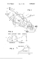
- FIG. 1 is a schematic and perspective view of a spectrophotometer embodying the invention
- FIG. 2 is a graph illustrating the output of the detector
- FIG. 3 is a graph of an exemplary analysis of the data.
- Spectrophotometer 10 designed to analyze a test sample 11 for the fluorescent properties thereof.
- the test sample may be a piece of dyed textile or optically brightened paint, paper or plastic.
- Spectrophotometer 10 includes a wide band radiant energy source 12 that provides light in both the ultraviolet and visible regions.
- the collimating lens 13 focuses or concentrates light from source 12 onto the intake of a light pipe system which coacts with a rotary member 14.
- Part of the light pipe system includes an illumination and collecting system 15, the details of the system and of member 14 being described in detail below.
- the outlet end of the light pipe system is connected to a detector 16 that produces an output signal I proportional to the intensity of the radiant energy received by detector 16.
- Member 14 is driven by a motor 22 which may be either a continuously driven or a digitally or incrementally driven motor, the motor being also connected to a conventional encoder 23 that provides signals indicating the angular position of member 14 from a reference position, in a manner known in the art.
- a motor 22 which may be either a continuously driven or a digitally or incrementally driven motor, the motor being also connected to a conventional encoder 23 that provides signals indicating the angular position of member 14 from a reference position, in a manner known in the art.
- the light pipe system includes a series of fiber optic bundles arranged in two paths, a reference path and a sample path.
- the reference path includes a bundle 24 that receives light from source 12 and transmits it towards rotary member 14.
- the end of bundle 24 adjacent member 14 is flatened to provide an elongated relatively thin end that is aligned with a similarly shaped end of a bundle 25 disposed on the other side of member 14.
- This bundle in turn has its other end similarly shaped and aligned with the flatened end of bundle 26 that is connected to detector 16.
- the elongated ends of bundles 24, 25 and 26 are located in a plane that passes diametrically through the axis of member 14.
- the sample path includes a bundle 27 that receives light from source 12 and transmits it toward member 14.
- a bundle 28 is disposed on the opposite side of member 14 and includes an end that forms part of system 15. In this connection, the end of 28 is the system is located at an angle perpendicular to the surface of sample 11.
- Four additional collection bundles 30 - 33 are disposed around the lower end of bundle 28 and at 45° to the surface so that light or energy from bundle 28 is reflected from the surface and part of such energy along with energy emitted due to fluorescense is picked up by these light collection bundles which form part of a fiber optic bundle 29. This bundle is aligned with a further bundle 34 connected to the detector.
- the light collection system may include a housing or hood 35 (shown in dotted outline for simplicity) which effectively shields stray light from the sample so as to not interfere with the measurements.
- a housing or hood 35 shown in dotted outline for simplicity
- other types of light illumination and collection systems such as conventional integrating spheres, may be used.
- Member 14 is circularly shaped and is of an opaque material. It has an opening 20 and a similar opening in which is mounted a variable interference type filter 21. Both opening 20 and filter 21 are shaped in the forms of sectors of an annulus located at the same distance from the axis of rotation on diametrically opposite sides thereof and subtending angles of 90° each.
- the filter 21, opening 20 and remaining portions of member 14 provide a track that is alternately filtered, opaque, open and opaque.
- the flat ends of the fiber optic bundles adjacent member 14 are aligned with this track. As the member 14 rotates, it controls the transmission of radiant energy between the aligned adjacent ends of the fiber optic bundles.
- Filter 21 is a wedge-type interference filter whose filtering characteristic varies uniformly from one end to the other so as to provide a wide band of radiant energy transmitted thereby.
- the filter is located relative to a zero reference position (described below) whereby the angular position of the filter corresponds to a given nominal wavelength, such wavelengths being determined by the widths of the adjacent portions of aligned bundles.
- filter 21 acts as a monochromator.
- the lower edge of filter 21, as viewed in FIG. 1, is arbitrarily designated at 0° and is used with the zero reference position whereby the wavelength being transmitted by filter 21 is proportional to the angular displacement of member 14.
- the zero reference position is determined when this 0° edge of filter 21 is aligned with the adjacent ends of bundles 27 and 28, at the "zero reference position" shown in FIG. 1.
- Filter 21 is arranged so that the 0° end passes the shortest wavelength of energy and the longer wavelengths are passed at the other end.
- sample 11 will be illuminated by a continuously variable monochromatic light over the range established by the filter.
- the filter varies uniformly to provide a wavelength bandwidth range from ⁇ l to ⁇ m.
- the light received by the light collection system includes not only that portion of the nominal wavelength that is reflected from the surface of 11 but it will also include those wavelengths that are generated due to the fluorescent properties of the material so that the light gathered by system 15 includes both the reflected and the fluorescent energy.
- the energy travels through bundle 29, through opening 20 and bundle 34 to detector 16 where the output I is proportional to the intensity of the incident radiant energy.
- the output I may vary as indicated.
- the output signal at a given wavelength ⁇ k is I s .
- the sample light path is blocked and the reference path is unblocked.
- Energy will pass along bundle 24, through filter 21, through bundle 25, opening 20 and bundle 26 to detector 16.
- the output signal I will follow a locus of points as shown in FIG. 2 representing the spectral characteristics of the light source.
- the sample and reference paths are exposed to the variable monochromatic light over a range of values.
- the sample and reference paths are exposed to polychromatic light where such light would first pass through opening 20 and then through filter 21, instead of the reverse direction as during the monochromatic excitation.
- the output signal I of detector 16 can be fed into an automatic system for analyzing the data, such a system being similar to the type shown in U.S. Pat. No. 3,751,643 -- Dill et al.
- the signal I is converted by an analog-to-digital converter and fed to a computer in conjunction with the encoding signals so that a series of digital values are produced that when plotted, would form a locus similar to that shown in FIG. 2.
- the respective monochromatic and polychromatic values are converted to the reflectance curves shown in FIG. 3. This is done, by the formula: ##EQU1##
- the spectrophotometer includes means compensating for dark current values of the system so as to produce the desired output signal I.
- I s and I r are the respective output signals corresponding to a given wavelength ⁇ k .
- the reflectance values for the polychromatic excitation are calculated and plotted.
- FIG. 3 is merely exemplary for an understanding of the invention.
Abstract
A spectrophotometer includes a wide band radiant energy source and a detector for providing an output signal proportional to the intensity of the radiant energy received thereby. A light pipe system is divided into a reference path and a sample path. Such system coacts with a rotary assembly having a variable monochromatic filter located diametrically opposite to an opening through which radiant energy can freely pass. The remaining portions of the rotary assembly are opaque so that as the assembly turns, the sample and reference paths are serially energized by monochromatic energy and then by polychromatic energy. The sample path includes a sample illumination and collection system for illuminating a test sample and collecting the light reflected therefrom. The resultant output of the detector can be analyzed to determine the amount of fluorescence.
Description
This invention relates to spectrophotometry and, more particularly, to a spectrophotometer particularly useful for analyzing the fluorescent properties of a material by a dual mode technique.
The dual or two mode method of analyzing materials for fluorescent properties by subjecting the materials to monochromatic and polychromatic excitation is a known method. It is described in "The Two-Mode Method for Measurement in Formulation with Fluorescent Colorants", by F. T. Simon, Journal of Color and Appearance, Vol. 1, No. 4, February/March 1972, pages 5-11. In accordance with this method, the test sample is alternately illuminated with monochromatic and polychromatic energy. The monochromatic energy is varied over a wide band and the reflectance of the material is determined across such band. Then, the sample is illuminated with polychromatic light and the light reflectance of the sample is again determined across the same bandwidth and the two results are compared to determine the degree of fluorescence.
In accordance with prior art techniques, spectrophotometers are available which operate both a monochromatic mode and a polychromatic mode. To perform the two mode technique, the measurements are first taken in the monochromatic mode, the spectrophotometer is then switched to the polychromatic mode and the further measurements are taken. Resultant data can then be analyzed either manually or by use of a computer.
One application where such a technique is particularly advantageous involves mixing paints or dyes to produce a resultant combination that matches a desired color. In attempting to predict a precise formula for producing the desired color, it has been customary to use the Kubelka-Munk formulas which are useful only in connection with the true spectralreflectance data without any distortions due to fluorenscence. The two mode technique provides such true spectral reflectance data.
One of the objects of the invention is to provide a spectrophotometer for analyzing fluorescent materials in accordance with the two mode technique.
Another object is to provide a spectrophotometer in which a test sample is excited or illuminated by a range of monochromatic energy and by polychromatic energy, without the need to switch the spectrophotometer between different modes of operation.
Still another object of the invention is to provide a spectrophotometer for analyzing fluorescent samples in accordance with the two mode technique, at relatively high speeds.
Briefly, in accordance with a preferred embodiment of the invention, a spectrophotometer has a wide band radiant energy source that is directed along two light pipe paths providing spectral data relative to the sample and to a reference. A rotary member intersects both light paths and includes a variable interference filter that transmits a narrow bandwidth of spectral energy over a wide range, the filter being disposed opposite to an opening through which light may freely pass. The energy which passes through the light pipes is fed to a detector providing an output signal. As the member rotates, the sample and reference paths are serially and alternately excited or provided with monochromatic and polychromatic energy so that the detector provides an output signal that can be analyzed to determine the fluorescent characteristics and true spectralreflectance of the material.
Other objects and advantages of the invention will be apparent from the following more particular description of a preferred embodiment of the invention taken in connection with the accompanying drawing, wherein:
FIG. 1 is a schematic and perspective view of a spectrophotometer embodying the invention;
FIG. 2 is a graph illustrating the output of the detector; and
FIG. 3 is a graph of an exemplary analysis of the data.
Referring now to the drawing, first to FIG. 1, there is illustrated a spectrophotometer 10 designed to analyze a test sample 11 for the fluorescent properties thereof. The test sample may be a piece of dyed textile or optically brightened paint, paper or plastic. Spectrophotometer 10 includes a wide band radiant energy source 12 that provides light in both the ultraviolet and visible regions. The collimating lens 13 focuses or concentrates light from source 12 onto the intake of a light pipe system which coacts with a rotary member 14. Part of the light pipe system includes an illumination and collecting system 15, the details of the system and of member 14 being described in detail below. The outlet end of the light pipe system is connected to a detector 16 that produces an output signal I proportional to the intensity of the radiant energy received by detector 16. Member 14 is driven by a motor 22 which may be either a continuously driven or a digitally or incrementally driven motor, the motor being also connected to a conventional encoder 23 that provides signals indicating the angular position of member 14 from a reference position, in a manner known in the art.
The light pipe system includes a series of fiber optic bundles arranged in two paths, a reference path and a sample path. The reference path includes a bundle 24 that receives light from source 12 and transmits it towards rotary member 14. The end of bundle 24 adjacent member 14 is flatened to provide an elongated relatively thin end that is aligned with a similarly shaped end of a bundle 25 disposed on the other side of member 14. This bundle in turn has its other end similarly shaped and aligned with the flatened end of bundle 26 that is connected to detector 16. The elongated ends of bundles 24, 25 and 26 are located in a plane that passes diametrically through the axis of member 14.
The sample path includes a bundle 27 that receives light from source 12 and transmits it toward member 14. A bundle 28 is disposed on the opposite side of member 14 and includes an end that forms part of system 15. In this connection, the end of 28 is the system is located at an angle perpendicular to the surface of sample 11. Four additional collection bundles 30 - 33 are disposed around the lower end of bundle 28 and at 45° to the surface so that light or energy from bundle 28 is reflected from the surface and part of such energy along with energy emitted due to fluorescense is picked up by these light collection bundles which form part of a fiber optic bundle 29. This bundle is aligned with a further bundle 34 connected to the detector. The light collection system may include a housing or hood 35 (shown in dotted outline for simplicity) which effectively shields stray light from the sample so as to not interfere with the measurements. Obviously, other types of light illumination and collection systems, such as conventional integrating spheres, may be used.
It will be appreciated that in the position shown in FIG. 1, light from source 12 travels through bundle 27, opening 20 and bundle 28 where it is reflected from sample 11. The light collected from system 15 then passes through bundle 29, filter 21 and bundle 34 to excite the detector so as to produce an output signal I proportional to the intensity. Because of the opaque nature of member 14, light from bundle 24 is prevented from travelling along the length of the reference path. In such a position, the sample is being excited or illuminated with a polychromatic radiant energy.
The lower edge of filter 21, as viewed in FIG. 1, is arbitrarily designated at 0° and is used with the zero reference position whereby the wavelength being transmitted by filter 21 is proportional to the angular displacement of member 14. The zero reference position is determined when this 0° edge of filter 21 is aligned with the adjacent ends of bundles 27 and 28, at the "zero reference position" shown in FIG. 1. The operations of the system for one revolution of the wheel would now be described, relative to an example. Filter 21 is arranged so that the 0° end passes the shortest wavelength of energy and the longer wavelengths are passed at the other end. As member 14 rotates from a zero position through the first 90°, sample 11 will be illuminated by a continuously variable monochromatic light over the range established by the filter. The filter varies uniformly to provide a wavelength bandwidth range from λl to λm. At any given wavelength, the light received by the light collection system includes not only that portion of the nominal wavelength that is reflected from the surface of 11 but it will also include those wavelengths that are generated due to the fluorescent properties of the material so that the light gathered by system 15 includes both the reflected and the fluorescent energy. The energy travels through bundle 29, through opening 20 and bundle 34 to detector 16 where the output I is proportional to the intensity of the incident radiant energy. Thus, as shown in FIG. 2 in an exemplary first 90° of rotation from the zero reference position, the output I may vary as indicated. The output signal at a given wavelength λk is Is. As a member rotates from 90° to 180°, the sample light path is blocked and the reference path is unblocked. Energy will pass along bundle 24, through filter 21, through bundle 25, opening 20 and bundle 26 to detector 16. As the wheel rotates, the output signal I will follow a locus of points as shown in FIG. 2 representing the spectral characteristics of the light source. Thus, for the first 180° of rotation, the sample and reference paths are exposed to the variable monochromatic light over a range of values. In a somewhat similar fashion, for the next 180°, the sample and reference paths are exposed to polychromatic light where such light would first pass through opening 20 and then through filter 21, instead of the reverse direction as during the monochromatic excitation.
It is to be appreciated that the output signal I of detector 16 can be fed into an automatic system for analyzing the data, such a system being similar to the type shown in U.S. Pat. No. 3,751,643 -- Dill et al. Preferably, the signal I is converted by an analog-to-digital converter and fed to a computer in conjunction with the encoding signals so that a series of digital values are produced that when plotted, would form a locus similar to that shown in FIG. 2.
To analyze the data, the respective monochromatic and polychromatic values are converted to the reflectance curves shown in FIG. 3. This is done, by the formula: ##EQU1## For this calculation, it is assumed that the spectrophotometer includes means compensating for dark current values of the system so as to produce the desired output signal I. Is and Ir are the respective output signals corresponding to a given wavelength λk. In a similar manner, the reflectance values for the polychromatic excitation are calculated and plotted. FIG. 3 is merely exemplary for an understanding of the invention. Because of the nature of the fluorescence material, wherein fluorescent emissions at a higher wavelength are due to excitation at a lower wavelength, that portion of the polychromatic curve that is below the monochromatic curve represents the true spectral reflectance of the material and that portion of the monochromatic curve below the polychromatic curve represents the true spectral reflectance at the higher regions where emissions due to fluorescence are high.
It should be apparent to those skilled in the art that changes may be made in the details and arrangements of parts without departing from the spirit and scope of the invention as defined in the appended claims.
Claims (10)
1. In a spectrophotometer for analyzing the fluorescent properties of a test sample, the combination comprising:
a wideband radiant energy source;
a radiant energy detector;
a light pipe system comprising a reference path operative to conduct radiant energy from said source to said detector, and a sample path operative to conduct radiant energy to said detector;
a movable opaque member disposed across said reference and sample paths and having an opening therein for transmitting radiant energy therethrough and a variable interference filter mounted therein for transmitting a variable narrow bandwidth of monochromatic radiant energy;
and means for moving said member relative to said system;
said opening and said filter being movable through positions aligned with said paths to expose said sample and reference paths alternately to monochromatic and polychromatic radiant energy during movement of said member.
2. The combination of claim 1 wherein:
said opaque member is circular and rotatable, said opening and said filter being at the same radial distance from the axis of rotation.
3. The combination of claim 2 wherein:
said opening and said filter are located in diametrically opposite positions and extend around different quadrants of said member.
4. The combination of claim 2 wherein:
said filter is uniformly graduated from one side of its quadrant to the other whereby the wavelength of the monochromatic energy transmitted thereby is proportional to the angular position thereof.
5. The combination of claim 4 comprising:
encoding means connected for rotation with said member providing signals at predetermined angular displacements.
6. In a spectrophotometer for analyzing the fluorescence of a test sample, the combination of:
a source of polychromatic radiant energy having a bandwidth including both ultraviolet and visible portions;
a radiant energy detector providing an output signal proportional to the intensity of radiant energy received thereby;
a movable member having a track therein comprising a variable filter for transmitting a variable wavelength of monochromatic radiant energy, a section for transmitting both monochromatic and polychromatic radiant energy, and an opaque portion for blocking the transmission of any radiant energy;
first fiber optic means having a first end disposed to receive light from said source and a second end disposed adjacent to one side of said track;
second fiber optic means having a first end disposed on the other side of said track and aligned with said second end of said first fiber optic means to receive radiant energy therefrom transmitted through said filter and said section when aligned therewith, said second fiber optic means having a second end disposed to illuminate said test sample with the radiant energy received by said second fiber optic means;
third fiber optic means having a first end for receiving radiant energy reflected from said sample and emitted by said sample due to fluorescence thereof, and a second end disposed adjacent one side of said track;
fourth fiber optic means having a first end aligned with said second end of said third fiber optic means on the opposite side of said track for receiving radiant energy transmitted through said filter and said section when aligned therewith, and a second end connected to said detector;
fifth fiber optic means having a first end disposed to receive radiant energy from said source and a second end disposed adjacent to said track;
sixth fiber optic means having first and second ends disposed adjacent to said track, said first end thereof being aligned with said second end of said fifth fiber optic means on the opposite side of said track for receiving radiant energy therefrom when aligned with said filters and said section;
seventh fiber optic means having first and second ends, said first end thereof being aligned with said second end of said sixth fiber optic means on the opposite side of said track, said second end thereof being connected to said detector;
and means for moving said member and track relative to said fiber optic means;
said track and said ends adjacent thereto being arranged whereby such movement:
during one period
aligns said filter with adjacent ends of said first and second fiber optic means to illuminate said sample with monochromatic energy,
aligns said section with adjacent ends of said third and fourth fiber optic means to transmit radiant energy from said sample to said detector, and aligns said opaque portion with said fifth, sixth and seventh fiber optic means;
during another period
aligns said section with adjacent ends of said first and second fiber optic means to illuminate said sample with polychromatic energy,
aligns said filter with adjacent ends of said third and fourth fiber optic means to transmit only a monochromatic portion of radiant energy from said sample to said detector,
and aligns said opaque portion with said fifth, sixth and seventh fiber optic means;
and during at least one more period
aligns said opaque portion with adjacent ends of said first, second, third and fourth fiber optic means,
and aligns said filter and said section with adjacent ends of said fifth, sixth and seventh fiber optic means to provide a reference for determining the reflectance from said sample.
7. The combination of claim 6 wherein:
said movable member is rotatable;
and said track is concentric to the axis of rotation.
8. The combination of claim 7 wherein:
said track comprises said filter located in one quadrant thereof, said section located in another quadrant thereof opposite to said one quadrant, and said opaque portion located between said one and said another quadrants.
9. The combination of claim 7 wherein:
said filter is uniformly graduated from one end to the other thereof along said track, whereby the wavelength of the monochromatic energy transmitted therethrough is proportional to the angular position thereof.
10. The combination of claim 9 comprising:
an encoder connected for rotation with said member and providing output signals indicative of the angular position thereof.
Priority Applications (9)
| Application Number | Priority Date | Filing Date | Title |
|---|---|---|---|
| US05/618,523 US3999062A (en) | 1975-10-01 | 1975-10-01 | Spectrophotometer for dual mode fluorescence analysis |
| GB33281/76A GB1506366A (en) | 1975-10-01 | 1976-08-10 | Spectrophotometer |
| FR7626306A FR2326693A1 (en) | 1975-10-01 | 1976-08-25 | DUAL MODE FLUORESCENT ANALYSIS SPECTROPHOTOMETER |
| CH1081176A CH595628A5 (en) | 1975-10-01 | 1976-08-26 | |
| IT27310/76A IT1077025B (en) | 1975-10-01 | 1976-09-17 | PERFECTED SPECTROMETER |
| DE2642170A DE2642170C2 (en) | 1975-10-01 | 1976-09-20 | spectrophotometer |
| JP51116078A JPS5243489A (en) | 1975-10-01 | 1976-09-29 | Spectrometer |
| ES451978A ES451978A1 (en) | 1975-10-01 | 1976-09-30 | Spectrophotometer for dual mode fluorescence analysis |
| CA262,459A CA1053925A (en) | 1975-10-01 | 1976-10-01 | Spectrophotometer for dual mode fluorescence analysis |
Applications Claiming Priority (1)
| Application Number | Priority Date | Filing Date | Title |
|---|---|---|---|
| US05/618,523 US3999062A (en) | 1975-10-01 | 1975-10-01 | Spectrophotometer for dual mode fluorescence analysis |
Publications (1)
| Publication Number | Publication Date |
|---|---|
| US3999062A true US3999062A (en) | 1976-12-21 |
Family
ID=24478068
Family Applications (1)
| Application Number | Title | Priority Date | Filing Date |
|---|---|---|---|
| US05/618,523 Expired - Lifetime US3999062A (en) | 1975-10-01 | 1975-10-01 | Spectrophotometer for dual mode fluorescence analysis |
Country Status (9)
| Country | Link |
|---|---|
| US (1) | US3999062A (en) |
| JP (1) | JPS5243489A (en) |
| CA (1) | CA1053925A (en) |
| CH (1) | CH595628A5 (en) |
| DE (1) | DE2642170C2 (en) |
| ES (1) | ES451978A1 (en) |
| FR (1) | FR2326693A1 (en) |
| GB (1) | GB1506366A (en) |
| IT (1) | IT1077025B (en) |
Cited By (25)
| Publication number | Priority date | Publication date | Assignee | Title |
|---|---|---|---|---|
| US4052616A (en) * | 1976-06-30 | 1977-10-04 | Cerberus Ag | Infrared radiation-burglary detector |
| US4119381A (en) * | 1976-12-17 | 1978-10-10 | Eastman Kodak Company | Incubator and radiometric scanner |
| US4155005A (en) * | 1977-09-08 | 1979-05-15 | Valtec Corporation | Fiber optic control system |
| EP0003015A1 (en) * | 1978-01-03 | 1979-07-11 | Howard Maurice Shapiro | Apparatus for non-invasive detection of zinc protoporphyrin in erythrocytes |
| US4262205A (en) * | 1979-09-21 | 1981-04-14 | Varian Associates, Inc. | Fluorometer with high sensitivity and stability |
| US4529308A (en) * | 1982-05-28 | 1985-07-16 | Hunter Associates Laboratory, Inc. | Spectrophotometer apparatus and method including scale drift correction feature |
| US4547666A (en) * | 1983-01-19 | 1985-10-15 | National Computer Systems, Inc. | Mark array sense reader with sequential output signals |
| EP0230679A1 (en) * | 1986-01-30 | 1987-08-05 | The Dow Chemical Company | Fiber-optic probe |
| US4693602A (en) * | 1984-11-06 | 1987-09-15 | Wyatt Technology Corporation | Method and apparatus for measuring the light scattering properties of small particles |
| EP0254204A2 (en) * | 1986-07-22 | 1988-01-27 | Pacific Scientific Company | Optical instrument employing fiber optics to direct light through tilting filter wheel |
| US4755054A (en) * | 1986-05-07 | 1988-07-05 | E-Squared Engineering, Inc. | Multichannel, optical-fiber-based spectrometer |
| US4801789A (en) * | 1986-07-07 | 1989-01-31 | Videx, Inc. | Replaceable reader head for optical code reader |
| EP0302565A2 (en) * | 1987-08-03 | 1989-02-08 | KADIA-Diamant Maschinen- und Werkzeugfabrik O. Kopp GmbH & Co. | Machining tool |
| US4968892A (en) * | 1986-12-24 | 1990-11-06 | General Electric Eompany | Fluorescent penetrant inspection sensor |
| GB2189623B (en) * | 1986-04-23 | 1991-01-30 | Kollmorgen Tech Corp | Remote reading spectrophotometer |
| US5015056A (en) * | 1989-09-12 | 1991-05-14 | Optec D.D. Melco Laboratory Co., Ltd. | Photointerruptor for use in light-transmission type rotary encoder |
| US5357343A (en) * | 1990-10-01 | 1994-10-18 | Eastman Kodak Company | Spectrophotometer having means for simultaneous modulation, switching and wavelength selection of a light source |
| US5386295A (en) * | 1990-10-01 | 1995-01-31 | Eastman Kodak Company | Postacquired spectrophotometers |
| US6097405A (en) * | 1996-09-30 | 2000-08-01 | Hewlett-Packard Company | Detection apparatus and method for use in a printing device |
| EP1498708A1 (en) * | 2002-04-23 | 2005-01-19 | Hiromu Maeda | Small packaged spectroscopic sensor unit |
| CN102563543A (en) * | 2011-05-09 | 2012-07-11 | 绎立锐光科技开发(深圳)有限公司 | Method and light source for generating high-brightness homogeneous light based on optical wavelength conversion |
| US9726335B2 (en) | 2011-09-22 | 2017-08-08 | Delta Electronics, Inc. | Phosphor device and manufacturing method thereof having a second phosphor agent to increase the luminous intensity of a converted color light |
| US10281810B2 (en) | 2011-09-22 | 2019-05-07 | Delta Electronics, Inc. | Projection apparatus comprising phosphor wheel coated with phosphor agents for converting waveband light |
| US10688527B2 (en) | 2011-09-22 | 2020-06-23 | Delta Electronics, Inc. | Phosphor device comprising plural phosphor agents for converting waveband light into plural color lights with different wavelength peaks |
| WO2020260448A1 (en) * | 2019-06-28 | 2020-12-30 | Protea Ltd | In-situ infra-red & ultra-violet photometer |
Families Citing this family (9)
| Publication number | Priority date | Publication date | Assignee | Title |
|---|---|---|---|---|
| GB2096352B (en) * | 1981-04-02 | 1985-04-11 | Abbott Lab | Fluorescence spectroscopy |
| JPS5847239A (en) * | 1981-09-14 | 1983-03-18 | Nisshin Denki Seisakusho:Kk | Liquid chromatograph apparatus |
| JPS6141780A (en) * | 1984-07-31 | 1986-02-28 | Mie Kounetsu Kk | Method and device for welding ceramic material to inside surface of tubular metallic blank material |
| DE3512744A1 (en) * | 1985-04-09 | 1986-10-16 | Brodhag, geb. Lebe, Helga, 8999 Scheidegg | Photometric rotation sensor for translucent originals |
| JPS62231608A (en) * | 1986-03-10 | 1987-10-12 | 今間 豊子 | Tableware receiver for stand-up dinner party |
| DE19615957A1 (en) * | 1996-04-22 | 1997-10-23 | Hans Joachim Bruins | Distribution device |
| AT1406U1 (en) * | 1996-05-31 | 1997-04-25 | Slt Labinstruments Gmbh | FLUOROMETER |
| DE19719422A1 (en) * | 1997-05-12 | 1998-11-19 | Matthias Dipl Ing Lau | Device for measuring fluorescence excited by light and its use |
| DE19936999C2 (en) * | 1999-08-02 | 2002-03-14 | Jena Optronik Gmbh | Arrangement for detecting the fluorescence radiation from matrix-shaped sample carriers |
Citations (2)
| Publication number | Priority date | Publication date | Assignee | Title |
|---|---|---|---|---|
| US3292484A (en) * | 1961-12-21 | 1966-12-20 | Rca Corp | Apparatus for monitoring spectral characteristics of substances |
| US3354319A (en) * | 1967-06-14 | 1967-11-21 | Bausch & Lomb | Optical illumination and sensing system including a plurality of optical fiber means |
Family Cites Families (6)
| Publication number | Priority date | Publication date | Assignee | Title |
|---|---|---|---|---|
| DE718434C (en) * | 1939-12-08 | 1942-03-12 | Siemens Ag | Push-pull photometer |
| US3393800A (en) * | 1965-10-21 | 1968-07-23 | Fred A. Durand Jr. | Method and apparatus for measuring light |
| GB1262322A (en) * | 1968-05-27 | 1972-02-02 | Douglas Graham Mitchell | Apparatus for spectroscopic analysis |
| US3733137A (en) * | 1971-01-12 | 1973-05-15 | Damon Corp | Log ratio transmittance signal processor for photometric apparatus |
| FR2142799B3 (en) * | 1971-06-25 | 1974-04-05 | Soulet Michel | |
| US3751643A (en) * | 1972-05-23 | 1973-08-07 | Ibm | System for performing spectral analyses under computer control |
-
1975
- 1975-10-01 US US05/618,523 patent/US3999062A/en not_active Expired - Lifetime
-
1976
- 1976-08-10 GB GB33281/76A patent/GB1506366A/en not_active Expired
- 1976-08-25 FR FR7626306A patent/FR2326693A1/en active Granted
- 1976-08-26 CH CH1081176A patent/CH595628A5/xx not_active IP Right Cessation
- 1976-09-17 IT IT27310/76A patent/IT1077025B/en active
- 1976-09-20 DE DE2642170A patent/DE2642170C2/en not_active Expired
- 1976-09-29 JP JP51116078A patent/JPS5243489A/en active Granted
- 1976-09-30 ES ES451978A patent/ES451978A1/en not_active Expired
- 1976-10-01 CA CA262,459A patent/CA1053925A/en not_active Expired
Patent Citations (2)
| Publication number | Priority date | Publication date | Assignee | Title |
|---|---|---|---|---|
| US3292484A (en) * | 1961-12-21 | 1966-12-20 | Rca Corp | Apparatus for monitoring spectral characteristics of substances |
| US3354319A (en) * | 1967-06-14 | 1967-11-21 | Bausch & Lomb | Optical illumination and sensing system including a plurality of optical fiber means |
Cited By (35)
| Publication number | Priority date | Publication date | Assignee | Title |
|---|---|---|---|---|
| US4052616A (en) * | 1976-06-30 | 1977-10-04 | Cerberus Ag | Infrared radiation-burglary detector |
| US4119381A (en) * | 1976-12-17 | 1978-10-10 | Eastman Kodak Company | Incubator and radiometric scanner |
| US4155005A (en) * | 1977-09-08 | 1979-05-15 | Valtec Corporation | Fiber optic control system |
| EP0003015A1 (en) * | 1978-01-03 | 1979-07-11 | Howard Maurice Shapiro | Apparatus for non-invasive detection of zinc protoporphyrin in erythrocytes |
| US4262205A (en) * | 1979-09-21 | 1981-04-14 | Varian Associates, Inc. | Fluorometer with high sensitivity and stability |
| US4529308A (en) * | 1982-05-28 | 1985-07-16 | Hunter Associates Laboratory, Inc. | Spectrophotometer apparatus and method including scale drift correction feature |
| US4547666A (en) * | 1983-01-19 | 1985-10-15 | National Computer Systems, Inc. | Mark array sense reader with sequential output signals |
| US4693602A (en) * | 1984-11-06 | 1987-09-15 | Wyatt Technology Corporation | Method and apparatus for measuring the light scattering properties of small particles |
| EP0230679A1 (en) * | 1986-01-30 | 1987-08-05 | The Dow Chemical Company | Fiber-optic probe |
| GB2189623B (en) * | 1986-04-23 | 1991-01-30 | Kollmorgen Tech Corp | Remote reading spectrophotometer |
| US4755054A (en) * | 1986-05-07 | 1988-07-05 | E-Squared Engineering, Inc. | Multichannel, optical-fiber-based spectrometer |
| US4801789A (en) * | 1986-07-07 | 1989-01-31 | Videx, Inc. | Replaceable reader head for optical code reader |
| EP0254204A2 (en) * | 1986-07-22 | 1988-01-27 | Pacific Scientific Company | Optical instrument employing fiber optics to direct light through tilting filter wheel |
| EP0254204A3 (en) * | 1986-07-22 | 1989-02-08 | Pacific Scientific Company | Optical instrument employing fiber optics to direct light through tilting filter wheel |
| US4968892A (en) * | 1986-12-24 | 1990-11-06 | General Electric Eompany | Fluorescent penetrant inspection sensor |
| EP0302565A3 (en) * | 1987-08-03 | 1989-03-29 | Kadia-Diamant Maschinen- Und Werkzeugfabrik O. Kopp Gmbh & Co. | Machining tool |
| WO1989000902A3 (en) * | 1987-08-03 | 1989-02-23 | Kadia Diamant | Machining tool with wear detection and system for measuring wear |
| WO1989000902A2 (en) * | 1987-08-03 | 1989-02-09 | Kadia-Diamant Maschinen- Und Werkzeugfabrik O. Kop | Machining tool with wear detection and system for measuring wear |
| EP0302565A2 (en) * | 1987-08-03 | 1989-02-08 | KADIA-Diamant Maschinen- und Werkzeugfabrik O. Kopp GmbH & Co. | Machining tool |
| US5015056A (en) * | 1989-09-12 | 1991-05-14 | Optec D.D. Melco Laboratory Co., Ltd. | Photointerruptor for use in light-transmission type rotary encoder |
| US5357343A (en) * | 1990-10-01 | 1994-10-18 | Eastman Kodak Company | Spectrophotometer having means for simultaneous modulation, switching and wavelength selection of a light source |
| US5386295A (en) * | 1990-10-01 | 1995-01-31 | Eastman Kodak Company | Postacquired spectrophotometers |
| US5526121A (en) * | 1990-10-01 | 1996-06-11 | Eastman Kodak Company | Variable filter spectrophotometers |
| US6097405A (en) * | 1996-09-30 | 2000-08-01 | Hewlett-Packard Company | Detection apparatus and method for use in a printing device |
| EP1498708A1 (en) * | 2002-04-23 | 2005-01-19 | Hiromu Maeda | Small packaged spectroscopic sensor unit |
| US20050036145A1 (en) * | 2002-04-23 | 2005-02-17 | Hiromu Meada | Small packaged spectroscopic sensor unit |
| EP1498708A4 (en) * | 2002-04-23 | 2005-07-13 | Hiromu Maeda | Small packaged spectroscopic sensor unit |
| CN102563543A (en) * | 2011-05-09 | 2012-07-11 | 绎立锐光科技开发(深圳)有限公司 | Method and light source for generating high-brightness homogeneous light based on optical wavelength conversion |
| US9175830B2 (en) | 2011-05-09 | 2015-11-03 | Apptronics (China) Corporation | Method for producing high-luminance monochromatic light based on optical wavelength conversion and light source |
| US9726335B2 (en) | 2011-09-22 | 2017-08-08 | Delta Electronics, Inc. | Phosphor device and manufacturing method thereof having a second phosphor agent to increase the luminous intensity of a converted color light |
| US10281810B2 (en) | 2011-09-22 | 2019-05-07 | Delta Electronics, Inc. | Projection apparatus comprising phosphor wheel coated with phosphor agents for converting waveband light |
| US10310363B2 (en) | 2011-09-22 | 2019-06-04 | Delta Electronics, Inc. | Phosphor device with spectrum of converted light comprising at least a color light |
| US10688527B2 (en) | 2011-09-22 | 2020-06-23 | Delta Electronics, Inc. | Phosphor device comprising plural phosphor agents for converting waveband light into plural color lights with different wavelength peaks |
| US10758937B2 (en) | 2011-09-22 | 2020-09-01 | Delta Electronics, Inc. | Phosphor device comprising plural phosphor agents for converting waveband light into plural color lights |
| WO2020260448A1 (en) * | 2019-06-28 | 2020-12-30 | Protea Ltd | In-situ infra-red & ultra-violet photometer |
Also Published As
| Publication number | Publication date |
|---|---|
| JPS5243489A (en) | 1977-04-05 |
| IT1077025B (en) | 1985-04-27 |
| JPS5616378B2 (en) | 1981-04-16 |
| CH595628A5 (en) | 1978-02-15 |
| ES451978A1 (en) | 1977-09-16 |
| DE2642170C2 (en) | 1984-12-20 |
| FR2326693B1 (en) | 1979-09-28 |
| FR2326693A1 (en) | 1977-04-29 |
| GB1506366A (en) | 1978-04-05 |
| DE2642170A1 (en) | 1977-04-14 |
| CA1053925A (en) | 1979-05-08 |
Similar Documents
| Publication | Publication Date | Title |
|---|---|---|
| US3999062A (en) | Spectrophotometer for dual mode fluorescence analysis | |
| CA1055721A (en) | Gloss measuring instrument | |
| US4477190A (en) | Multichannel spectrophotometer | |
| US7365842B2 (en) | Light scanning type confocal microscope | |
| CA1091967A (en) | Cam filter wheel for tilting optical filters | |
| EP0174722B1 (en) | Fluorometer | |
| JP2703680B2 (en) | Spectrophotometer with simultaneous light source modulation, switching and wavelength selection means | |
| US5952660A (en) | Method of identifying post consumer or post industrial waste carpet utilizing a hand-held infrared spectrometer | |
| WO2001023848A1 (en) | Spectrometer and method for measuring optical spectrum | |
| US3598994A (en) | Method and apparatus for sensing fluorescent substances | |
| WO1982000717A1 (en) | Method and apparatus for photometric detection in fluids | |
| US3519816A (en) | Stream analyzer for radiation absorption analysis of a plurality of components | |
| Vo-Dinh et al. | Phase-resolved fiber-optics fluoroimmunosensor | |
| US5305077A (en) | High-resolution spectroscopy system | |
| KR100460972B1 (en) | Method and apparatus for identifying discarded carpet using hand-held infrared spectrometer | |
| CA1249138A (en) | Simultaneous multiple wavelength photometer | |
| SU1414328A3 (en) | Method of measuring difference in color content of two specimens | |
| EP0176826A2 (en) | Method and apparatus for dual-beam spectral transmission measurements | |
| DE1472144A1 (en) | Spectrophotometer | |
| US4017191A (en) | Two-beam photometer with rotatable graded interference filter | |
| US3342099A (en) | Scattered light spectrophotometer | |
| US3372282A (en) | Color coding optical reticle | |
| US3600092A (en) | Apparatus for measuring density stimulus values of three primary colors | |
| SU1004878A1 (en) | Fibrous sheet material humidity determination method | |
| SU1060953A1 (en) | Method of measuring intensity of lens in optical spectrum |