US3738257A - Turret type coring unit - Google Patents
Turret type coring unit Download PDFInfo
- Publication number
- US3738257A US3738257A US00153552A US3738257DA US3738257A US 3738257 A US3738257 A US 3738257A US 00153552 A US00153552 A US 00153552A US 3738257D A US3738257D A US 3738257DA US 3738257 A US3738257 A US 3738257A
- Authority
- US
- United States
- Prior art keywords
- fruit
- carriage
- turret
- cups
- coring
- Prior art date
- Legal status (The legal status is an assumption and is not a legal conclusion. Google has not performed a legal analysis and makes no representation as to the accuracy of the status listed.)
- Expired - Lifetime
Links
Images


Classifications
-
- A—HUMAN NECESSITIES
- A23—FOODS OR FOODSTUFFS; TREATMENT THEREOF, NOT COVERED BY OTHER CLASSES
- A23N—MACHINES OR APPARATUS FOR TREATING HARVESTED FRUIT, VEGETABLES OR FLOWER BULBS IN BULK, NOT OTHERWISE PROVIDED FOR; PEELING VEGETABLES OR FRUIT IN BULK; APPARATUS FOR PREPARING ANIMAL FEEDING- STUFFS
- A23N4/00—Machines for stoning fruit or removing seed-containing sections from fruit, characterised by their stoning or removing device
- A23N4/12—Machines for stoning fruit or removing seed-containing sections from fruit, characterised by their stoning or removing device for coring fruit
Abstract
A machine for stemming, coring and slicing pears includes a horizontal plane indexing turret having six fruit cups moving to feed, stemming, coring, slicing and idle stations. The cups are pivotally supported by a discharge cam. The tools are mounted on a vertically reciprocating nonrotatable carriage above the turret, so that one individual operation is performed at each station. The cups have jaws that are opened slightly at the slicing station and closed at the stemming station.
Description
United States Patent 1 Manfre et a1.
TURRET TYPE CORING UNIT Inventors: Ben Louis Manfre; Peter Werner Forcella, both of San Jose, Calif.
Assignee: FMC Corporation, San Jose, Calif.
Filed: June 16, 1971 Appl. No.: 153,552
US. Cl 99/547, 99/545 Int. Cl A23n 3/08 Field of Search 146/52; 99/545, 547
References Cited UNITED STATES PATENTS 2/1967 Anderson 146/52 X 2/1944 Erickson 146/52 June 12, 1973 2,227,794 1/1941 Phillips 146/52 3,319,678 5/1967 Anderson 146/52 Primary Erqn i ierwillie G. Abercrombie Attorney-F. W. Anderson and C. E. Tripp [57] ABSTRACT A machine for stemming, coring and slicing pears includes a horizontal plane indexing turret having six fruit cups moving to feed, stemming, coring, slicing and idle stations; The cups are pivotally supported by a discharge cam. The tools are mounted on a vertically reciprocating nonrotatable carriage above the turret, so that one individual operation is performed at each station. The cups have jaws that are opened slightly at the slicing station and closed at the stemming station.
8 Claims, 21 Drawing Figures PAIENTED I 2 I975 m m E V W BEN L. MANFRE PETER W. FORCELLA ATTORNEYS TURRET TYPE CORING UNIT DESCRIPTION OF PRIOR ART The U.S. Pat. Nos. to Anderson 3,199,558, Aug. 10, 1965; Anderson 3,269,441, Aug. 30, 1966; and Anderson 3,351,114, Nov. 7, 1967 disclose a belt-type fruit cup conveyor above which a row of stemming, coring and slicing tools is mounted on an oscillating carriage.
The U.S. Pat. to Chamberlin No. 3,305,074, Feb. 21, 1967 shows a fruit cup with gear sector connected jaws that can be opened and closed along a belt conveyor.
The U.S. Pat. to Bridge No. 2,437,637, Mar. 9, 1948 shows a horizontal plane indexed fruit cup turret with a set of coring and slicing tools for each cup mounted to rotate with the turret and reciprocated by a fixed barrel cam.
The U.S. Pat. to Perkins No. 3,396,766, Aug. 13, 1968, discloses an artichoke preparation machine having an indexed turret, carrying gripping jaws which carry the fruits past a saw, beneath a rotary cutter and beneath a core pruner, the latter two tools being raised and lowered individually by cam controlled fluid cylinders.
The U.S. Pat. to Deitz No. 2,076,496, Apr. 6, 1937, shows a tomato coring and peeling machine having an indexed table with fruit receiving openings, a vertically reciprocating nonrotatable carriage. The fruit is simultaneously cored from below and peeled by a carriage mounted peeler, after which the table carries the cored and peeled fruit over a rotary knife to slice off the tops. A hold-down on the carriage functions at the slicing station.
The U.S. Pat. to Thompson No. 2,526,712, Oct. 24, 1950, (FIGS. 8 and 32) shows cammed jaw members on a transfer turret that can be closed to center the fruit for transfer.
In the U.S. Pat. to Gardiner, No. 2,788,037, Apr. 9, 1957, the tools rotate with the turret and the fruit is gripped between upper and lower fingers.
The U.S. Pat. to Pease No. 2,509,781, May 30, 1950, shows spring loaded apple gripping jaws.
The U.S. Pat. to Gardiner No. 1,886,388, Nov. 8, 1932, shows an artichoke trimming and coring machine having a Geneva drive for the table.
SUMMARY OF THE INVENTION The present invention represents a simple turret type coring unit that can be fed and attended to by one operator and which simultaneously performs a stemming, coring and slicing operation for each indexed position of the turret, but on different fruits. A peeled fruit such as a pear is placed in a cup at the feed station, and a stemmed, cored and sliced pear is correspondingly discharged from a discharge station remote from the feed station. This is accomplished by arranging a series of at least five fruit cups on a horizontal plane, indexed turret. A vertically reciprocating, nonrotatable carriage is mounted above the turret which carriage has circumferentially spaced stemming, coring and slicing tools that operate simultaneously on different fruits when the carriage is brought down toward the fruits in the circumferentially spaced row of fruit cups on the turret. The entire cups are pivotally mounted on the turrets and supported in a manner which causes their fruit receiving openings to face up for feeding and for operation by the tools, but when each cup reaches the discharge station, its support is removed, whereby the entire cup falls down about its pivot causing discharge of the processed fruit.
Another feature of the invention is that the fruit cups themselves have jaws that can open and close slightly. Althoughthis is known generally in the art (see the Chamberlin patent), in accordance with the present invention, means synchronized with the reciprocation of the vertically moving carriage opens the cup jaws slightly during the slicing operation and the jaws remain open until their cups reach the stemming tools, whereupon the jaws are closed somewhat to center the pears in the cups for stemming. The jaws remain closed until the cups are again under the slicing tool.
Another feature of the invention relates to simple mechanism for causing discharge of sliced processed pears from the turret. As previously mentioned, and as opposed to the United States Bridge patent, each entire cup is pivotally mounted on the turret, the pivot being off center relative to the vertical axis of the cup. The undersides of the cups are supported by cam rollers which ride along the upper surface of a fixed cam beneath the turret. A relief portion of the fixed cam accommodates falling of the cups from their upwardly facing position to a horizontal position for discharge of the processed fruits at the discharge station.
Another feature of the invention is that a single motor driven camshaft reciprocates the nonrotatable tool mounting carriage, indexes the turret and operates a stem ejector in the stemming tube. Thus, with the relatively simple fruit processing apparatus of the present invention, a machine tended by a single operator can, for example, stem, core and slice peeled pears or the like at the rate of about 15 30 per minute.
DETAILED DESCRIPTION OF THE DRAWINGS FIG. 1 is a plan diagram of the turret of the present invention showing the various work stations.
FIG. 2 is a perspective diagram of the machine.
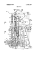
FIG. 3 is a side view of the machine looking toward the coring tool.
FIGS. 3A and 3B are sections taken as indicated on FIG. 3.
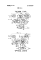
FIG. 4 is a section of the machine along lines 4 4 of FIG. 3.
FIG. 5 is a plan view of one of the cups.
FIG. 6 is a side elevation of one of the cups with parts broken away.
FIG. 7 is a section taken on line 7 7 of FIG. 6.
FIG. 8 is a section taken on line 8 8 of FIG. 6.
FIG. 9 is a perspective view of one of the cups showing how it is supported by the cup cam.
FIG. 10 is a developed view at the discharge station.
FIG. 11 is a fragmentary section showing the cup opening operation at the slicing station.
FIGS. 12 to 17A are sequential operational diagrams of the stemming unit.
GENERAL DESCRIPTION Referring to FIGS. 1 and 2, the apparatus embodying the present invention is indicated at 10 and includes a horizontal plane indexed turret plate T mounted on a vertical shaft 11. I
The turret T is circumferentially apertured to receive six fruit cups 20, and is indexed through the angular spacing between these cups. The cups 20 are normally disposed with their upper edges flush with the top of the turret plate T.
A vertically reciprocating carriage 12 is slidably mounted on the shaft 11 by a sleeve 13. The carriage 12 mounts a stemming tool ST, a coring tool C and a slicer S so that these tools are brought down against the fruit in fruit cups 20, and are retracted therefrom by reciprocation of the carriage. The turret T also provides a feed station F and a discharge station D, there being an idle station X between the discharge and feed stations. The shaft 1 1 for the turret is indexed by a Geneva gear assembly having a driven wheel 14 (FIG. 2) mounted on the shaft 11 and rotated by a driver 16 operated from a gear box 18 of conventional design. The gear box 18 is driven by a gear box sprocket 21, a chain 22, a camshaft sprocket 24 mounted on. a camshaft 26, a camshaft driving sprocket 28, a chain 30 and a sprocket 31 on a planetary reducer 32, the latter being driven by a motor M.
The carriage 12 is lowered to bring the tools down against the fruit in cups 20 and retracted by a cam 40 (FIG. 2) mounted on the cam shaft 26 that operates a bell crank cam follower mechanism indicated generally at 42 and connected to the carriage in a manner to be described in detail presently.
The stemming tool ST includes a stemming tube 110 and a stem ejector rod 120 (FIG. 3) which will also be described in detail presently. The stem ejector rod 120 must be operated independently of the carriage l2 and this is accomplished by a cam 50 (FIG. 2) on the camshaft 26, operating an ejector cam bell crank follower mechanism indicated generally at 52.
The coring unit C has a rotary knife 180 (FIG. 3) which is rotated by means of a gear box 54 (FIG. 2) driven by a V-belt and pulley assembly 56 from the motor M. A flexible shaft 58 shown fragmentarily in FIG. 2 connects the gearbox 54 to the coring unit 60 for rotating the coring knife 180.
Thus, to summarize, the general mode of operation of the invention thus far described, assume the turret to be empty. An operator places a peeled pear in the cup 20 at the feed station F when the turret is stationary and the carriage retracted to an upper position. The turret is then indexed by the Geneva gearing 14, 16 to transport the pear from the feed station F to a zone beneath the stemming tool ST whereupon the turret momentarily stops. The cam mechanism 50,52 lowers the carriage 12 which stems the fruit and ejects the stem from the stemming tube by means of the cam 50 and the cam follower arm 52 which will be described presently.
During the descent of the carriage, an operator will place another pear in the feed station F and this will take place during every dwell period of the turret.
The first stemmed pear P will be indexed to the coring tool C which is brought down by the carriage 12 against the fruit and the rotating coring knife 180 enters the hole produced by the stemmer ST to remove the seed cells in a manner generally known in the art. The next indexing of the carriage brings the first stemmed and cored fruit beneath the slicer S whereupon the carriage l2 descends again and the slicing tool S halves the fruit. As will be seen, each cup 20 has moveable jaws and these jaws will be closed for stemming and coring but will be opened somewhat during tion (FIG. 10) in a manner to be described presently, for discharge of the halved pear P to a discharge chute 59. The cups are returned to their fruit receiving position and each cup passes through an idle station X (FIGS. 1 and 2) at which no operation is performed.
Carriage FIGS. 3, 3A, 3B and 4 show important details of the carriage tool assembly and their mounting on the frame of the machine. Referring to these figures, the frame work is made up of structural elements including base elements 60, rear vertical posts 62 (FIG. 3), front vertical posts 64,64a (FIG. 4) and upper frame elements 66. The vertical shaft 11 for the turret is mounted in lower bearings (FIG. 4) on the lower frame elements and upper bearings 72 on the upper frame elements. The gear box for the Geneva drive 16 is mounted on frame elements 67 (FIG. .4) in a manner not critical to the present invention. As mentioned, the carriage indicated generally at 12 is formed with a vertical sleeve 13 that surrounds the vertical turret shaft 11 and from which projects a lateral flange 78. (FIGS. 3A and 4). As seen in FIGS. 3A and 4, an outer edge plate 79 on the flange 78 reciprocates in a vertical guide 80 secured to the vertical frame element 64, thereby preventing rotation of the carriage as it is reciprocated.
As best seen in FIG. 3, the carriage reciprocating follower mechanism 42 includes a bell crank 82 pivoted to the frame at 84 by means of a bracket 86 projecting from a transverse frame element 88. One end of the bell crank 82 mounts a cam follower roller 90 and the other end is pivoted at 91 to a link 92, the lower end of which is pivoted at 93 to an ear 94 projecting from the carriage flange 78 (FIGS. 3, 3A and 4). The link 92 provides a turnbuckle type adjustment to accommodate refinements in the lowermost position of the carriage. Thus, rotation of the cam shaft 26 and the carriage reciprocating cam 40 oscillates the bell crank 82 and hence reciprocates the carriage 12 vertically along the turret shaft 11.
Stemming Tool Continuing the general description of the apparatus, the construction of the stemming tool S will now be described in connection with FIGS. 3 to 4. Subsequently, the operation of that tool will be described in more detail relative to the diagrams of FIGS. 12 to 17A. A frame bracket projects from the vertical frame element 64 (FIG. 4) and mounts a horizontal platform 102 (see also FIGS. 3 and 3B). Upstanding from the platform 102 is a fixed cylindrical guide member 104 (FIG. 3) and projecting up from the guide is a hold-down rod 106. The long stemming tube 110, having a sharpened lower end, is mounted for vertical reciprocation with the carriage 12. The stemming tube is secured to the carriage 12 by means of frame brackets 112, 114, best seen in FIG. 3, these brackets being bolted to the carriage plate 78 previously mentioned. A latch release pin 113 projects up from the lower bracket 112 (FIG. 12 et seq.). The stemming tube 110, being fixed to the bracket 114, reciprocates with the carriage and hence when the carriage descends, the stemming tube is forced through the stem zone of the pears P in the cup 20. that is disposed at the stemming station.
. As best seen in FIGS. 12 17, a hold-down is provided to keep the pears in their cups when the stemming tube is withdrawn after the stemming operation (FIG. This hold-down structure is provided in the form of a centrally apertured pad 119 (see also FIG. 3) that receives the stemming tube 110 and which pad is slideably mounted in the guide 104 previously described by means of rods 122 extending upwardly from the pad. The upper ends of the rods 122 mount a latch support plate 124 having an angled latch support block 126 that loosely mounts a latch plate 128 by means of a bolt 130 on the block 126. The latch plate 128 is apertured to slideably receive the hold-down rod 106 previously described and its action will be described in detail in conjunction with FIGS. 12 to 17A, as previously mentioned. The stem ejector rod 120 reciprocates within the stemming tube 110 and is independently reciprocated by the cam 50 and the linkage indicated generally at 52, as previously mentioned. Specifically, the upper end of the stem ejector rod 120 is pivoted at 121 (FIG. 3) to one end of a bell crank lever 123, which lever is pivoted at 123a to ears 127 projecting from the frame. The other end of the bell crank lever 123 has a roller 129 (FIG. 3) that bears on the stem ejector cam 50 previously described. A spring 123b is connected between the bell crank lever 123 and the frame to hold the roller 129 against the cam 50. As seen in FIGS. 3 and 12, the upper portion of the core ejector rod 120 mounts a piston 132 that fits within a cylinder 134 and this assembly serves simply as a suction mechanism for the stemming tool, as described in U.S. Pat. to Anderson No. 3,351,114.
Coring Tool The general arrangement of the coring tool C will now be described. The internal construction of this unit and the details thereof are not critical to the present invention and the unit disclosed herein is constructed like that of the US. Pat. to Anderson No. 3,35l,l14, Nov. 7, 1967 assigned to the FMC Corporation. The coring tool C is slidably mounted on the carriage so that after the knife 180 enters the fruit the carriage can continue to descend. Linkages extend between the carriage and the coring unit which operate tool elements after the coring tool is stopped by the fruit and the carriage continues its descent.
The frame platform 102,102a and an upper frame platform 140,140a (FIGS. 3A and 4) assist in locating the coring tool. The coring tool includes a housing 142 which is secured to vertical guide rods 144 (FIGS. 3 and 4) that slide in the frame platforms 102a, 140a and which can also slide in a bracket 146 (FIG. 3) projecting from the carriage plate 78. The upper ends of the guide rods 144 mount a pad 148 that supports the coring tool on the carriage 12 and establish its normal position on the carriage. Compression springs 150 extend between the frame bracket 140a and the upper end of the housing 142 for the coring tool and hence resiliently urge the coring tool in its lowermost position on the carriage 12, as determined by the pad 148 and the carriage bracket 146 (FIG. 3).
As seen in FIGS. 38 and 4, the housing 142 for the coring tool C is pivotally connected at 155 to a lower operating link 156, the other end of which is pivoted at 157 to a short link 158 pivotally mounted by eye 159 on the frame 64. An upper operating link 160 (FIGS. 3A and 4) is pivoted to the coring tool housing 142 at 161 (FIG. 4) and to a link 162 on an L-shaped bracket 164 supported by the carriage plate 78 (FIG. 3A). The
6 coring knife projects down from the coring tool (FIG. 3).
As mentioned, the internal construction of the coring unit described is disclosed completely in the aforesaid U.S. Anderson Pat. No. 3,351,114, and the details thereof are not critical to the present invention. For purposes of the present invention it need only be stated that as the carriage descends, the coring tool C descends also, until the tool is brought down against the upper end of the pear, after this, the slide mounting of the housing 142 on the carriage by means of the guide rods 144 permits further descent of the carriage but the coring tool hangs back, without damage to the pear. However, the operating links 146,160 (FIG. 4) are operated by relative motion of the carriage and the coring tool housing and cause further descent of the coring knife 180 into the stem hole previously produced at the stemming tool S as well as providing a radially outward motion of the coring knife 180. The coring knife 180 is constantly rotated by an internal connection shown in the aforesaid Anderson patent to the flexible shaft 58, which shaft is driven by the gear box 54 and the motor M in a manner previously described. As a result of the construction, the previously stemmed fruit, such as a pear in a cup 20 below the coring tool C, will be internally cored as the carriage continues to descend after it has brought the coring tool against the fruit.
Slicing Tool In the apparatus of the present invention, the slicing tool S is provided to halve the previously stemmed and cored fruit, such as the pears being described by way of example, at the station that follows the coring station. This operation is performed in a very simple manner by providing a tapered slicing knife (FIG. 3) which is mounted on a rod 192 secured to a plate 193 (FIG. 3A) on the carriage sleeve 13. The knife 190 has a pilot tip 194 (FIG. 3). Thus the slicing knife 190 descends in synchronism with the stemming and coring tools and cuts the pears in the cups 20 disposed at the slicing station into halves, while the pears remain in the cups. As will be explained presently, the cups have jaws which can move somewhat between an open and a closed position. These jaws will have been closed for the stemming and coring operations in order to center the fruit, but will be opened somewhat for the slicing operation in order to provide clearance for the slicing knife and so that the two halves produced by the slicing operation can spread apart slightly and thus obviate crushing of the fruit due to the jaw pressure by the cups during the slicing operations.
Fruit Cups FIGS. 5 8 show constructional details of the fruit cups 20 and FIGS. 9 and 10 show how these cups are pivotally mounted for discharge and the discharge station D. FIG. 11 shows how the cup jaws can be opened for the slicing operation, as previously mentioned.
Referring to FIGS. 5 9 for details of the cup construction, each cup 20 has a unitary body member 200 which is channeled at its upper fruit receiving portion to receive opposed jaws 202,204. The body member 200 has an annular guide pocket 206 (FIG. 8) which is apertured at 208 (FIG. 8) to avoid interference with the descending tools. Projecting upwardly from the annular guide pocket 206 are fixed fruit receiving pocket members 210 (FIGS. 5 and 9). The fruit receiving pocket is completed by the jaws 202,204, previously mentioned. The cup jaws 202,204 are pivoted to the body 200 by means of pins 202a, 204a respectively projecting through ears 204 on the fixed body 200 as best seen in the FIG. 7. As seen in FIG. 6, the jaws 202,204 are geared together for symmetrical opening and closing motion by pairs of interengaging toothed sectors 211,212, these sectors also appearing in plan in FIG. 7.
The cup jaw 202 has an operating arm 202b and the cup jaw 204 has a similar arm 204b (FIGS. 6 and 7). With this construction raising or lowering either arm 202b or 204b will symmetrically open both jaws 202,204 and holding either arm in any one position will cause both jaws to remain in a corresponding position.
As previously mentioned, the cups 20 are pivotally mounted at one side on the turret T so that the jaws can be released for discharging processed fruit. This construction is best seen in FIGS. 5, 9 and 10. In order to mount the cups 20 on the turret T, ears 220 are secured to a block 222 (FIGS. and 10) and this block is secured to the underside of the turret T. These ears provide spaced pivotal supports for the cups by means of a pivot pin 226 (FIGS. 5 and 9) which extends through the cup body 200 and the turret ears 220.
The position of each pivotably mounted cup is individually determined by a cam and roller assembly that operates at the discharge station D to lower the cup for discharging the processed fruit. This is accomplished by connecting a cross plate 228 to the pin 226, previously described, and to a similar pin 226a (FIG. 5) whereby the crossplate is secured to the cup body 200. At the side of the cup opposite the pivot pin 226, that is adjacent the pin 226a (FIGS. 5 and 9), a cup support roller 230 is mounted on a stub shaft 232 that projects radially inwardly from the remote end of the crossplate 228. This roller rides on a cup cam 240 which is a barrel type cam disposed below the turret (FIGS; 3 and 4) and which has a relieved sector 242 at the discharge station D, best seen in the developed view of FIG. 10. Thus at every station except the discharge station D, the roller 230 supports the cups on the upper planar surface 244 of the cam 240 so that its jaws face upwardly for receiving and guiding a pear P. At the discharge station D, the roller 230 drops into the relief zone 242 of the cup cam allowing the cup at that station to pivot about the pin 226 to a horizontal position for discharge of the processed pears P into the chute 59 (FIG. 4). The cup is restored as the roller sides up the cam ramp 242a. This action is clearly shown in the developed view of FIG. 10. Stop bolts 245 (FIG. 10) prevent upward bounce of the raised cups, and stop-bolts 246 limit downward pivoting of the cups during discharge.
FIG. 11 shows how the cup jaws 202,204 can be opened to accommodate the slicing knife 190 of the slicer S for the purposes previously described. At the slicing station, a link 250 (FIGS. 3 and 11) has a lost motion sliding and pivotal connection 252 (FIG. 3) with the carriage reciprocating bell crank 82. When the carriage descends, the link 250 descends. The lower end of the link 250 is slotted at 254 to slide over a fixed guide pin 256 on the lower frame element 60. The link 250 carries at its lower end an adjustably mounted cup opening finger 258 which is in the path of the jaw opening arm 204b previously described. A spring 260 between the finger 258 and the lower frame element 60 holds the link 250 resiliently in its lowermost position but accommodates some overtravel by the bell crank 82 because of the pin and slot connection 252 (FIG. 3) between the link 250 and the bell crank. When the bell crank arm 82 lowers the carriage, the link 250 is thus moved downwardly as indicated by the arrow in FIG. 11, and at this time the turret T will have been indexed to position a cup 20 so that its jaw opening arm 204b is disposed beneath the finger 258. Thus, the descending finger 258 opens the jaw 204 and by means of the gear sectors 211, the other jaw 202 is opened by an equal amount. This provides clearance for the slicing knife. The cup parts just described are so constructed that there is enough friction in the pivotal mountings of the jaws 202,204 so that they will remain open until they are positively closed in a manner which will now be described.
As just described, the cup jaws 202,204 are opened at the slicing station, remain open for discharge of the fruit at the discharge station D, and are still open at the idle station X and at the feed station F. However, after pears have been fed into cups at the feed station, the jaws are closed to center the fruit for the stemming and coring operations that follow.
The jaw closing function is performed by a pair of resiliently mounted cam rods 270 (FIG. 3) there being one of these cam rods situated to close the jaws by the time the cup reaches the stemming tool S and another insures that the jaws are held closed at the coring tool C. The cam rods 270, which are identical, are pivotally mounted to the lower portion of the cup cam 240 at 272 and are resiliently held in their uppermost positions by compression springs 274 (see also FIG. 12). The springs 274 surround stop rods 276 depending from the cams 270, and having heads that engage brackets 278 on the cup cam for determining the uppermost position of the cam rods 270. Thus, when the cups with their jaws opened, approach the stemming tool ST at the stemming station, the jaw operating fingers 202b ride over the first cam rod 270 which closes the jaws. If, by any chance, the jaws open or partially open during indexing of the cup from the stemming tool to the coring tool, they are again closed or at least are held closed by the second cam rod 270. There are no cam rods 270 at the other stations of the turret, in order that the jaws can be opened at the slicing station by the finger 258, as previously described and in order that they will remain open when the cups reach the feed station F.
Stemming Tool Details As previously mentioned, FIGS. 12 17A are step by step diagrams showing operation of the stemming tool S, the general construction of which has been previously described.
In FIG. 12, a pear P is in the cup 20 at the stemming station below the stemming tool ST and with the jaws 202,204 closed by the cam rod 270 as previously described. The carriage 12 is in its uppermost position and the stemming tube and the core ejector rod are in their uppermost or retracted positions. The hold-down pad 119 is in its lowermost position, being supported by the latch support plate 124 on the bracket 112 of the carriage. The latch release pin 113 has raised the latch plate 128 to its release position relative to the fixed stop rod 106.
In FIG. 13, the carriage 12 has descended sufficiently to bring the hold-down pad 119 against the upper face of the pear P in the cup and hence the hold-down pad 119, the associated guide rods 122 and latch support plate 124 on those rods can move down no further. However, the carriage l2 continues to descend, lowering the stemming tube 110 towards the pear in the cup. The latch release pin 113 on the carriage plate 112 is now lowered relative to the immobilized latch support pad 124, which permits the latch plate 128 to drop to its latching position relative to the frame mounted rod 106. However, the latch has no effect on the apparatus at this time because the only part that is moving is the carriage and the partsassociated therewith, and the latch plate 128 operates only on the fixed stop rod 106. The bell crank 123 for operating the stem ejector rod 120 is moving the ejector rod down with the stemming tube 110 up to this point, in response to the contour of the stem ejector cam 150 (FIG. 3). Further downward motion of the carriage will cause the stemming tube 110 to move down relative to the stem ejector rod 120 because the contour of the stem ejector cam 50 is such that the ejector rod is held stationary for a period of time at the carriage position shown in FIG. 13.
In FIG. 14, the carriage 12 has descended to its lowermost position so that the stemming tube 110 has cut loose the stem portion W of the pear. Also, as indicated in dotted lines at the top of the figure, the mechanism for the stem ejector rod 120 has again been set in motion to lower the stem ejector rod and eject the stem material M from the stemming tube 120 as is also indicated in FIG. 14.
In FIG. 15, the carriage 12 is now being raised by its cam 40 and associated linkage. This retracts the stemming tube 110 from the stemmed pear in the cup and the stem ejector rod 120 moves upwardly with the stemming tube in response to the contour of the stemming cam 50.
In FIG. 16, the carriage is still rising along with the stemming tube. The stem ejector rod is also being raised at a velocity to match that of the carriage.
In both FIGS. 15 and 16, the hold-down pad 119 holds the pear in the cup as the stemming tools are raised. This action is insured by the latch mechanism as is shown in somewhat enlarged form in 15A. Upward frictional force exerted by the stemming tube 110 on the stemmed pear, tends to lift the pear from the cup on the retraction motion of the carriage 12, but is resisted by the hold-down pad 119 acting through the latch plate 128 against the fixed latch rod 106. As seen in FIG. 3, the rod 106 is on the cylindrical guide 104 that in turn is mounted on the frame 102 of the apparatus. A very slight initial upward motion of the holddown pad 119 (in response to the aforesaid lifting action on the pear by stemming tube 120) lifts the latch mechanism relative to the fixed rod 106. This causes the edges of the aperture 128a in the latch plate 128 that surrounds the fixed rod 106 to bite into the rod 106 and prevents further upward motion of the holddown assembly.
The latching effect takes place until the carriage rises to the position shown in FIGS. 17 and 17A. Here the latch release pin 113 on the carriage plate 112 engages the latch plate 128 and lifts it slightly, thereby relieving the biting or latching action of that plate against the fixed rod 106. Just after this release, the plate 112 that moves with the carriage engages the latch support pad 124 on the hold-down assembly and causes the entire hold-down assembly to 'move upwardly with the carriage. The latch plate slides freely up along the fixed latch rod 106. Thus, free retraction of the carriage towards its uppermost position is accommodated until the parts reach the uppermost position of FIG. 12 for a new cycle. The latch is not released again for future action until the carriage reaches the position shown in FIG. 13 on its next downward stroke.
Brief Summary of the Operation The operation of the fruit processing machine of the present invention will now be summarized briefly. A single operator tends the machine and as the turret T is indexed and stops, the operator places a peeled pear P in the cup 20 at the feed station F. The cup will be in its normal upwardly facing condition, and the jaws 202,204 will be open at this time. The carriage 12 will be in an upper or retracted position.
The Geneva mechanism 14, 16 now indexes the turret T through an angle of 60 bringing the newly loaded cup underneath the stemming tool ST. The jaw operating finger 2021) will ride up on the first spring loaded cam 270 (FIGS. 3 and 12) to close the jaws for centering the pear in the cup.
When the freshly loaded cup is stopped beneath the stemming tool ST, the carriage cam moves the carriage 12 down and retracts it again to perform the stemming operation previously described in detail in connection with FIGS. 12 17.
After the stemming operation is completed the turret is again indexed and the cup containing the stemmed pear is brought beneath the coring tool C. The cup jaws 202,204 are still held in their closed position by the second cam rod 270 (FIG. 3) during the coring operation to maintain alignment of the fruit in the cup.
The carriage now descends to bring the coring tool down against the fruit whereupon relative motion of the coring tool and the descending carriage causes, through the links 156,160 (FIG. 4), advance of the coring knife into the fruit coupled with a radial motion of the knife to remove the seed cells. The knife 180 is being constantly rotated by the motor 54 and the flexible shaft 58 as previously described. This operation, as mentioned before is described in detail in the aforesaid U.S. Pat. to Anderson No. 3,351,114.
After the coring has been completed, the carriage retracts, and the turret is indexed to bring the cored pear to the slicing tool S. At this time the carriage again descends to bring the slicing knife down for halving the fruit in the cup. Before the slicing begins, the descending carriage lowers the link 250 (FIGS. 3 and 11) to cause the finger 258 to engage the cup jaw arm 204b and open both jaws 202,204 to provide clearance for the sliced fruit without binding on the slicing knife 190.
The carriage is again retracted to its uppermost position by the carriage cam 40 and the turret is indexed to bring the cup containing the cored and halved fruit to the discharge station D. As the cup approaches the discharge station, the cup supporting roller 230 drops off the upper edge 244 (FIG. 10) of the cup cam 240 and falls into the relieved portion 242 of that cam causing the cup to pivot about the pin 226 to a horizontal position so that the halved pear P falls out into the chute 59 (FIG. 4).
The carriage again retracts, raising tools, whereupon the turret indexes another 60 to the idle station X. Indexing of the turret causes the cup suppo'rt roller 230 to ride up the ramp portion 224a of the cam 240, thereby restoring the cup to its uppermost position, flush with the turret T, whereupon the upper edge 244 of the cam 240 holds the cup in that position. The cup will be in substantial engagement with the lower end of the stop screw 245 (FIG. at this time. The restored cup reaches the idle station X in a condition ready to receive fruit and with its jaws remaining in their open condition imparted at the slicing station.
The last indexing of the cup being followed through the machine returns it to the feed station F for the insertion of another pear. Only a single cup has been traced through the machine in the preceding operational description. Actually, the operator will place a pear in each cup 20 as it reaches the feeding station F and accordingly there will be a pear under each of the three tools, the stemming tool ST, the coring tool C and the slicer S so that a halved pear is discharged for every 60 indexing of the turret T.
Thus it can be seen that a pear can be rapidly stemmed, cored and sliced by a simple apparatus under the attendance of a single operator, who must only feed pears one at a time to a readily accessible and stationary feed cup. The simplicity and compactness of the machine of the present invention renders it useful in certain commercial conditions wherein the more complex horizontal conveyor row-type machine of the aforesaid Anderson patent cannot be economically warranted.
Although the best mode contemplated for carrying out the present invention has been herein shown and described, it will be apparent that modification and variation may be made without departing from what is regarded to be the subject matter of the invention.
We claim:
1. Fruit preparation apparatus of the type comprising a frame, a horizontal plane turret on said frame, a plurality of circumferentially mounted fruit receiving means mounted on said turret, a single vertically reciprocating, nonrotatable tool mounting carriage on said frame, fruit processing tool means all on said carriage, means forming a discharge station for processed fruit, means providing a feed station between said discharge station and said tool means, and drive means for alternately indexing said turret and for reciprocating said carriage to cause said tool means to process the fruit; the improvement wherein said fruit receiving means comprises a plurality of cups having opposed operable and closable jaws, said tool means comprising a coring tool and a flat slicing blade for halving the fruit, said blade being circumferentially spaced from the coring tool, means for closing said cup jaws at said coring tool, and means for partially opening said cup jaws at said slicing blade to provide clearance for the blade.
2. Apparatus for coring and slicing fruit of the type comprising a frame, a horizontal plane turret on said frame, circumferentially spaced fruit cups on said turret, a vertically reciprocating carriage nonrotatably mounted on said frame, means forming a discharge station for processed fruit, means providing a feed station following said discharge station, and drive means for alternately indexing said turret and reciprocating said carriage to process the fruit; the improvement comprising spaced individual stemming, coring and slicing tools on said carriage for simultaneously performing these three operations individually on the fruit in three of said fruit cups, said fruit cups being pivotally mounted in their entirety on the turret about radial axes at one side of the cups, cam means for normally supporting the other side of the cups, in their upwardly facing positions, and cam means causing said cups to pivot downwardly and rearwardly in their entirety at said dis charge station and restoring the cups to their normal, upwardly facing positions before they return to said feed station.
3. The apparatus of claim 2, wherein said cups are normally supported with their upper edges flush with the top of said turret.
4. Apparatus for coring and slicing fruit of the type comprising a frame, a horizontal plane turret on said frame, circumferentially spaced fruit cups on said turret, a vertically reciprocating carriage nonrotatably mounted on said frame, means forming a discharge station for processed fruit, means providing a feed station following said discharge station, and drive means for alternately indexing said turret and reciprocating said carriage to process the fruit; the improvement comprising spaced individual stemming, coring and slicing tools on said carriage for simultaneously performing these three operations individually on the fruit in three of said fruit cups, said cups comprising opposed jaws that can be partially opened and closed, means for partially opening the jaws at said slicing tool, said jaws remaining open at said feed station, and means for closing said jaws before they reach said coring tool.
5. The apparatus of claim 4, comprising means for operating said cup jaw closing means to close the jaws in response to descent of said carriage.
6. The apparatus of claim 5, wherein said jaw opening means comprises mechanism coupling the jaws for simultaneous operation, and cam means beneath said turret for engagement by an abutment on one of said jaws to close both jaws.
7. Apparatus for coring and slicing fruit of the type comprising a frame, a horizontal plane turret on said frame, circumferentially spaced fruit receivers on said turret, a vertically reciprocating carriage nonrotatably mounted on said frame, means forming a discharge station for processed fruit, means providing a feed station following said discharge station, and drive means for alternately indexing said turret and reciprocating said carriage to process the fruit; the improvement comprising spaced individual stemming, coring and slicing tools on said carriage for simultaneously performing these three operations individually on the fruit in three of said fruit receivers, a camshaft on said frame, a carriage reciprocating cam on said camshaft, cam follower means for reciprocating the entire carriage and the tools therein, means for driving said camshaft in synchronism with said drive means, said stemming tool comprising a stemming tube that moves with said carriage and a stem ejector rod slidable in said tube, an ejector rod reciprocating cam on said camshaft, and ejector rod cam follower means for independently reciprocating said ejector rod.
8. Apparatus for coring fruit comprising a frame, a generally horizontal plane turret on said frame, a plurality of circumferentially mounted fruit cups pivotally mounted in their entirety on said turret along one of their sides, the tops of said cups being normally flush with the top of said turret, means for normally holding the cups up in their upwardly facing position flush with said turret, a single, vertically reciprocating, nonrotatable carriage on said frame, processing stations respecfor releasing the cups to swing down about their pivots for causing fruit to be discharged from the cups that leave the last tool, means providing a feed station for a cup disposed between said discharge station and the first tool, and drive means for alternately indexing said turret and moving said carriage down to cause said tools to engage and process the fruit.
Claims (8)
1. Fruit preparation apparatus of the type comprising a frame, a horizontal plane turret on said frame, a plurality of circumferentially mounted fruit receiving means mounted on said turret, a single vertically reciprocating, nonrotatable tool mounting carriage on said frame, fruit processing tool means all on said carriage, means forming a discharge station for processed fruit, means providing a feed station between said discharge station and said tool means, and drive means for alternately indexing said turret and for reciprocating said carriage to cause said tool means to process the fruit; the improvement wherein said fruit receiving means comprises a plurality of cups having opposed operable and closable jaws, said tool means comprising a coring tool and a flat slicing blade for halving the fruit, said blade being circumferentially spaced from the coring tool, means for closing said cup jaws at said coring tool, and means for partially opening said cup jaws at said slicing blade to provide clearance for the blade.
2. Apparatus for coring and slicing fruit of the type comprising a frame, a horizontal plane turret on said frame, circumferentially spaced fruit cups on said turret, a vertically reciprocating carriage nonrotatably mounted on said frame, means forming a discharge station for processed fruit, means providing a feed station following said discharge station, and drive means for alternately indexing said turret and reciprocating said carriage to process the fruit; the improvement comprising spaced individual stemming, coring and slicing tools on said carriage for simultaneously performing these three operations individually on the fruit in three of said fruit cups, said fruit cups being pivotally mounted in their entirety on the turret about radial axes at one side of the cups, cam means for normally supporting the other side of the cups, in their upwardly facing positions, and cam means causing said cups to pivot downwardly and rearwardly in their entirety at said discharge station and restoring the cups to their normal, upwardly facing positions before they return to said feed station.
3. The apparatus of claim 2, wherein said cups are normally supported with their upper edges flush with the top of said turret.
4. Apparatus for coring and slicing fruit of the type comprising a frame, a horizontal plane turret on said frame, circumferentially spaced fruit cups on said turret, a vertically reciprocating carriage nonrotatably mounted on said frame, means forming a discharge station for processed fruit, means providing a feed station following said discharge station, and drive means for alternately indexing saiD turret and reciprocating said carriage to process the fruit; the improvement comprising spaced individual stemming, coring and slicing tools on said carriage for simultaneously performing these three operations individually on the fruit in three of said fruit cups, said cups comprising opposed jaws that can be partially opened and closed, means for partially opening the jaws at said slicing tool, said jaws remaining open at said feed station, and means for closing said jaws before they reach said coring tool.
5. The apparatus of claim 4, comprising means for operating said cup jaw closing means to close the jaws in response to descent of said carriage.
6. The apparatus of claim 5, wherein said jaw opening means comprises mechanism coupling the jaws for simultaneous operation, and cam means beneath said turret for engagement by an abutment on one of said jaws to close both jaws.
7. Apparatus for coring and slicing fruit of the type comprising a frame, a horizontal plane turret on said frame, circumferentially spaced fruit receivers on said turret, a vertically reciprocating carriage nonrotatably mounted on said frame, means forming a discharge station for processed fruit, means providing a feed station following said discharge station, and drive means for alternately indexing said turret and reciprocating said carriage to process the fruit; the improvement comprising spaced individual stemming, coring and slicing tools on said carriage for simultaneously performing these three operations individually on the fruit in three of said fruit receivers, a camshaft on said frame, a carriage reciprocating cam on said camshaft, cam follower means for reciprocating the entire carriage and the tools therein, means for driving said camshaft in synchronism with said drive means, said stemming tool comprising a stemming tube that moves with said carriage and a stem ejector rod slidable in said tube, an ejector rod reciprocating cam on said camshaft, and ejector rod cam follower means for independently reciprocating said ejector rod.
8. Apparatus for coring fruit comprising a frame, a generally horizontal plane turret on said frame, a plurality of circumferentially mounted fruit cups pivotally mounted in their entirety on said turret along one of their sides, the tops of said cups being normally flush with the top of said turret, means for normally holding the cups up in their upwardly facing position flush with said turret, a single, vertically reciprocating, nonrotatable carriage on said frame, processing stations respectively comprising circumferentially spaced individually different coring tools all supported on said single carriage for simultaneous vertical motion with the carriage, means mounting said coring tools on said carriage for accommodating additional descent of the carriage after the tools engage fruits on said cups, said tools simultaneously performing different coring operations on fruit in said cups, means at a discharge station for releasing the cups to swing down about their pivots for causing fruit to be discharged from the cups that leave the last tool, means providing a feed station for a cup disposed between said discharge station and the first tool, and drive means for alternately indexing said turret and moving said carriage down to cause said tools to engage and process the fruit.
Applications Claiming Priority (1)
| Application Number | Priority Date | Filing Date | Title |
|---|---|---|---|
| US15355271A | 1971-06-16 | 1971-06-16 |
Publications (1)
| Publication Number | Publication Date |
|---|---|
| US3738257A true US3738257A (en) | 1973-06-12 |
Family
ID=22547680
Family Applications (1)
| Application Number | Title | Priority Date | Filing Date |
|---|---|---|---|
| US00153552A Expired - Lifetime US3738257A (en) | 1971-06-16 | 1971-06-16 | Turret type coring unit |
Country Status (5)
| Country | Link |
|---|---|
| US (1) | US3738257A (en) |
| AR (1) | AR193094A1 (en) |
| FR (1) | FR2141831A1 (en) |
| IT (1) | IT968278B (en) |
| ZA (1) | ZA722421B (en) |
Cited By (13)
| Publication number | Priority date | Publication date | Assignee | Title |
|---|---|---|---|---|
| US3886857A (en) * | 1973-04-18 | 1975-06-03 | Richard J Goodale | Apparatus for coring cauliflower heads |
| US4112838A (en) * | 1976-06-23 | 1978-09-12 | Altman James E | Halving and calyx removing apparatus for pears and the like |
| US4157681A (en) * | 1976-11-29 | 1979-06-12 | Produits Findus S.A. | Machine for paring vegetables or fruits |
| US5699725A (en) * | 1996-05-20 | 1997-12-23 | Poltielov; Neris | System for preparing baked apples and other edible fruits and vegetables |
| US5870949A (en) * | 1998-04-24 | 1999-02-16 | Ashlock Company, A Division Of Vistan Corporation | Pitting apparatus with box cam; wiping blade, or separating assembly |
| USRE37321E1 (en) * | 1996-05-20 | 2001-08-14 | Neris Poltielov | System for preparing baked apples and other edible fruits and vegetables |
| US20100243497A1 (en) * | 2007-06-04 | 2010-09-30 | Chih-Ching Hsieh | Pivotable tool box |
| US8586118B1 (en) * | 2010-02-02 | 2013-11-19 | Gene Baca | Method of using a gravity wheel de-stemmer |
| CN104432417A (en) * | 2014-12-17 | 2015-03-25 | 华东交通大学 | Full-automatic red date pitter |
| CN105852147A (en) * | 2016-06-23 | 2016-08-17 | 河北工业大学 | Spherical melon and fruit peeling, coring and slicing machine |
| CN108783473A (en) * | 2018-07-02 | 2018-11-13 | 李义飞 | A kind of jujube processing unit (plant) |
| CN108902996A (en) * | 2018-07-02 | 2018-11-30 | 李义飞 | Jujube stoning slice all-in-one machine |
| US10863863B2 (en) * | 2017-06-30 | 2020-12-15 | Grillworks Llc | Grill height adjustment and indicator mechanism and methods of use thereof |
Citations (4)
| Publication number | Priority date | Publication date | Assignee | Title |
|---|---|---|---|---|
| US2227794A (en) * | 1939-02-24 | 1941-01-07 | Jr Benjamin F Phillips | Canning apparatus |
| US2342131A (en) * | 1942-02-10 | 1944-02-22 | Barron Gray Packing Company | Apparatus for trimming artichokes |
| US3305071A (en) * | 1965-09-13 | 1967-02-21 | Fmc Corp | Fruit preparation machine |
| US3319678A (en) * | 1962-07-02 | 1967-05-16 | Fmc Corp | Fruit processing machine with means to align tool with work |
-
1971
- 1971-06-16 US US00153552A patent/US3738257A/en not_active Expired - Lifetime
-
1972
- 1972-04-11 ZA ZA722421A patent/ZA722421B/en unknown
- 1972-06-02 AR AR242331A patent/AR193094A1/en active
- 1972-06-06 IT IT50716/72A patent/IT968278B/en active
- 1972-06-12 FR FR7221067A patent/FR2141831A1/fr not_active Withdrawn
Patent Citations (4)
| Publication number | Priority date | Publication date | Assignee | Title |
|---|---|---|---|---|
| US2227794A (en) * | 1939-02-24 | 1941-01-07 | Jr Benjamin F Phillips | Canning apparatus |
| US2342131A (en) * | 1942-02-10 | 1944-02-22 | Barron Gray Packing Company | Apparatus for trimming artichokes |
| US3319678A (en) * | 1962-07-02 | 1967-05-16 | Fmc Corp | Fruit processing machine with means to align tool with work |
| US3305071A (en) * | 1965-09-13 | 1967-02-21 | Fmc Corp | Fruit preparation machine |
Cited By (15)
| Publication number | Priority date | Publication date | Assignee | Title |
|---|---|---|---|---|
| US3886857A (en) * | 1973-04-18 | 1975-06-03 | Richard J Goodale | Apparatus for coring cauliflower heads |
| US4112838A (en) * | 1976-06-23 | 1978-09-12 | Altman James E | Halving and calyx removing apparatus for pears and the like |
| US4157681A (en) * | 1976-11-29 | 1979-06-12 | Produits Findus S.A. | Machine for paring vegetables or fruits |
| US5699725A (en) * | 1996-05-20 | 1997-12-23 | Poltielov; Neris | System for preparing baked apples and other edible fruits and vegetables |
| USRE37321E1 (en) * | 1996-05-20 | 2001-08-14 | Neris Poltielov | System for preparing baked apples and other edible fruits and vegetables |
| US5870949A (en) * | 1998-04-24 | 1999-02-16 | Ashlock Company, A Division Of Vistan Corporation | Pitting apparatus with box cam; wiping blade, or separating assembly |
| US20100243497A1 (en) * | 2007-06-04 | 2010-09-30 | Chih-Ching Hsieh | Pivotable tool box |
| US7841677B2 (en) * | 2007-06-04 | 2010-11-30 | Chih-Ching Hsieh | Pivotable tool box |
| US8586118B1 (en) * | 2010-02-02 | 2013-11-19 | Gene Baca | Method of using a gravity wheel de-stemmer |
| CN104432417A (en) * | 2014-12-17 | 2015-03-25 | 华东交通大学 | Full-automatic red date pitter |
| CN105852147A (en) * | 2016-06-23 | 2016-08-17 | 河北工业大学 | Spherical melon and fruit peeling, coring and slicing machine |
| CN105852147B (en) * | 2016-06-23 | 2017-12-15 | 河北工业大学 | A kind of spherical melon and fruit, which is peeled, is enucleated valve cutting machine |
| US10863863B2 (en) * | 2017-06-30 | 2020-12-15 | Grillworks Llc | Grill height adjustment and indicator mechanism and methods of use thereof |
| CN108783473A (en) * | 2018-07-02 | 2018-11-13 | 李义飞 | A kind of jujube processing unit (plant) |
| CN108902996A (en) * | 2018-07-02 | 2018-11-30 | 李义飞 | Jujube stoning slice all-in-one machine |
Also Published As
| Publication number | Publication date |
|---|---|
| AR193094A1 (en) | 1973-03-30 |
| IT968278B (en) | 1974-03-20 |
| FR2141831A1 (en) | 1973-01-26 |
| ZA722421B (en) | 1973-01-31 |
Similar Documents
| Publication | Publication Date | Title |
|---|---|---|
| US3738257A (en) | Turret type coring unit | |
| US4453458A (en) | Food processing apparatus | |
| US4206697A (en) | Method and apparatus for selective pitting of fruits of the drupe type | |
| US3696847A (en) | Apple slicer and celler | |
| US4109021A (en) | Method of peeling pineapples | |
| US5074203A (en) | Coring apparatus | |
| US2403516A (en) | Fruit halving and pitting machinery | |
| US5156874A (en) | Method for slicing broccoli and the like into spears | |
| US3162225A (en) | Fruit corer | |
| US2226664A (en) | Fruit handling and treating machine | |
| US5009909A (en) | Coring method | |
| US2652085A (en) | Fruit pitting and halving machine | |
| GB1195342A (en) | Contour Peeler | |
| US2627709A (en) | Candy wrapping machine | |
| US3035620A (en) | Fruit preparation machine | |
| US3396766A (en) | Artichoke machine | |
| US2558205A (en) | Cherry pitter | |
| US2367859A (en) | Fruit juice extractor | |
| US2895587A (en) | Egg cracking mechanism | |
| US3018179A (en) | Pear peeling, coring and trimming machine and method and product thereof | |
| US3156277A (en) | Fruit preparation machine | |
| US3061070A (en) | Fruit handling machine | |
| US3016076A (en) | Fruit orientator and corer | |
| US2682900A (en) | Citrus fruit reamer | |
| US4262025A (en) | Method for selective pitting of fruits of the drupe type |