US3552257A - Fastener adapted for wire cage - Google Patents
Fastener adapted for wire cage Download PDFInfo
- Publication number
- US3552257A US3552257A US815328A US3552257DA US3552257A US 3552257 A US3552257 A US 3552257A US 815328 A US815328 A US 815328A US 3552257D A US3552257D A US 3552257DA US 3552257 A US3552257 A US 3552257A
- Authority
- US
- United States
- Prior art keywords
- nut
- bolt
- fastener
- shank
- wire
- Prior art date
- Legal status (The legal status is an assumption and is not a legal conclusion. Google has not performed a legal analysis and makes no representation as to the accuracy of the status listed.)
- Expired - Lifetime
Links
- 229920003023 plastic Polymers 0.000 claims description 29
- 230000002093 peripheral effect Effects 0.000 claims description 2
- 239000000463 material Substances 0.000 description 12
- 229910052751 metal Inorganic materials 0.000 description 10
- 239000002184 metal Substances 0.000 description 10
- 244000144977 poultry Species 0.000 description 8
- 235000013594 poultry meat Nutrition 0.000 description 8
- 229920003002 synthetic resin Polymers 0.000 description 8
- 239000000057 synthetic resin Substances 0.000 description 8
- 238000010276 construction Methods 0.000 description 6
- XLYOFNOQVPJJNP-UHFFFAOYSA-N water Substances O XLYOFNOQVPJJNP-UHFFFAOYSA-N 0.000 description 6
- 229930182556 Polyacetal Natural products 0.000 description 3
- 229920006324 polyoxymethylene Polymers 0.000 description 3
- 125000000391 vinyl group Chemical group [H]C([*])=C([H])[H] 0.000 description 3
- 229920002554 vinyl polymer Polymers 0.000 description 3
- 241000287828 Gallus gallus Species 0.000 description 2
- 229910000831 Steel Inorganic materials 0.000 description 2
- FPIPGXGPPPQFEQ-OVSJKPMPSA-N all-trans-retinol Chemical compound OC\C=C(/C)\C=C\C=C(/C)\C=C\C1=C(C)CCCC1(C)C FPIPGXGPPPQFEQ-OVSJKPMPSA-N 0.000 description 2
- 235000013330 chicken meat Nutrition 0.000 description 2
- 238000004519 manufacturing process Methods 0.000 description 2
- 229910001220 stainless steel Inorganic materials 0.000 description 2
- 239000010959 steel Substances 0.000 description 2
- 229920004943 Delrin® Polymers 0.000 description 1
- 229920005177 Duracon® POM Polymers 0.000 description 1
- 229910001335 Galvanized steel Inorganic materials 0.000 description 1
- 235000017349 Tetrapleura tetraptera Nutrition 0.000 description 1
- 240000008374 Tetrapleura tetraptera Species 0.000 description 1
- 239000011717 all-trans-retinol Substances 0.000 description 1
- 235000019169 all-trans-retinol Nutrition 0.000 description 1
- 229910052782 aluminium Inorganic materials 0.000 description 1
- XAGFODPZIPBFFR-UHFFFAOYSA-N aluminium Chemical compound [Al] XAGFODPZIPBFFR-UHFFFAOYSA-N 0.000 description 1
- 238000005452 bending Methods 0.000 description 1
- 229910010293 ceramic material Inorganic materials 0.000 description 1
- 239000011248 coating agent Substances 0.000 description 1
- 238000000576 coating method Methods 0.000 description 1
- 230000000295 complement effect Effects 0.000 description 1
- 239000002131 composite material Substances 0.000 description 1
- 235000013601 eggs Nutrition 0.000 description 1
- 239000008397 galvanized steel Substances 0.000 description 1
- 229920001903 high density polyethylene Polymers 0.000 description 1
- 238000001746 injection moulding Methods 0.000 description 1
- JEIPFZHSYJVQDO-UHFFFAOYSA-N iron(III) oxide Inorganic materials O=[Fe]O[Fe]=O JEIPFZHSYJVQDO-UHFFFAOYSA-N 0.000 description 1
- 238000000034 method Methods 0.000 description 1
- 230000004048 modification Effects 0.000 description 1
- 238000012986 modification Methods 0.000 description 1
- 229920005989 resin Polymers 0.000 description 1
- 239000011347 resin Substances 0.000 description 1
- 230000000717 retained effect Effects 0.000 description 1
- 239000010935 stainless steel Substances 0.000 description 1
- 229910052725 zinc Inorganic materials 0.000 description 1
- 239000011701 zinc Substances 0.000 description 1
Images


Classifications
-
- F—MECHANICAL ENGINEERING; LIGHTING; HEATING; WEAPONS; BLASTING
- F16—ENGINEERING ELEMENTS AND UNITS; GENERAL MEASURES FOR PRODUCING AND MAINTAINING EFFECTIVE FUNCTIONING OF MACHINES OR INSTALLATIONS; THERMAL INSULATION IN GENERAL
- F16B—DEVICES FOR FASTENING OR SECURING CONSTRUCTIONAL ELEMENTS OR MACHINE PARTS TOGETHER, e.g. NAILS, BOLTS, CIRCLIPS, CLAMPS, CLIPS OR WEDGES; JOINTS OR JOINTING
- F16B37/00—Nuts or like thread-engaging members
- F16B37/16—Wing-nuts
-
- F—MECHANICAL ENGINEERING; LIGHTING; HEATING; WEAPONS; BLASTING
- F16—ENGINEERING ELEMENTS AND UNITS; GENERAL MEASURES FOR PRODUCING AND MAINTAINING EFFECTIVE FUNCTIONING OF MACHINES OR INSTALLATIONS; THERMAL INSULATION IN GENERAL
- F16B—DEVICES FOR FASTENING OR SECURING CONSTRUCTIONAL ELEMENTS OR MACHINE PARTS TOGETHER, e.g. NAILS, BOLTS, CIRCLIPS, CLAMPS, CLIPS OR WEDGES; JOINTS OR JOINTING
- F16B35/00—Screw-bolts; Stay-bolts; Screw-threaded studs; Screws; Set screws
- F16B35/02—Screw-bolts; Stay-bolts; Screw-threaded studs; Screws; Set screws divided longitudinally
Definitions
- the fastener can secure another wire or plate to be held to a support wire by inserting the support wire together with a second wire into the notch, or inserting the support wire only into the notch and passing the notched shank through an aperture of a plate, and screwing a wing nut towards them.
- the present invention relates to a novel fastener of nut and bolt type, and more particularly, to a novel and improved fastener adapted for a wire cage.
- the fastener of nut and bolt type of this invention has been invented and developed in order to adapt itself particularly to wire cage use in the field of poultry husbandry.
- the novel fastener of this invention is advantageous for use in every field of construction and assembly work, such as assembly of mechanical and electronic parts.
- the cage system for poultry production is widely employed because it has several advantages that the laying of eggs can be discerned at a glance, poultry raising can be effected in a three-dimensional manner just as the floor system.
- a series of cages are continuously provided on a continuous rack construction, single row, split stairsteps, back to back or double deck, and besides, a watering trough together with a feed trough is installed in front of cages.
- a steel wire which constitutes a preferred cage has a diameter of about 2.5 3-mm. and is coated with a -zinc coating.
- a relatively expensive stainless steel wire and an aluminum wire are also used. No matter what material the wire may be,-the diameter thereof for use in cage making is in the range of 2.5 3 mm. described above,.hence it was inconvenient and impractical for the wire to serve as a stable support when considering the hanging a holder thereon to support a trough.
- a clip and the link now commonly employed have never been met with satisfaction as a fastening means which secures something to a single wire.
- This invention proposes to overcome the above disadvantages and to provide a novel and improved fastening means adapted particularly for a singlewire of cage, said fastener being fabricated by cutting out an axial notch wide enough to accommodate a single wire therein from the central portion of bolt shank and'having preferably a wingnut to be engaged vide a novel fastener of nut and bolt type which is effective for supporting a single wire which constitutes a wire construction,
- It is another object of the inventionjto provide a novel fastener of nut and bolt type which is-adapted to secure a holder for a water trough as well as a feed trough to a single wire of cage in a simple, safe", effective-and convenient manner.
- FIG. 1 is a side view of a metallic or other material bolt of this invention, showing some of its relative dimensions;
- FIG. 2 is a longitudinal sectional view of a plastic bolt of this invention
- FIG. 3 is a longitudinal sectional view of a plastic wingnut engageable with the bolt of FIG. 3, showing a side view of a central, axially extended reenforcing rod;
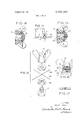
- FIG. 4 is a perspective view of a modified bolt, the shank of which being cut into four portions by a cruciform slotway;
- FIG. 5 shows a sectional view wherein two wires are clamped as by the bolt 1 of FIG. 1;
- FIG. 6 is a perspective view in which a holder for supporting a water or feed trough in front of the cage is secured to a wire thereof by the fastener of this invention
- FIG. 7 is a sectional view of FIG. 6 taken along the line 7-7;
- FIG. 8 is a sectional view of a modified wingnut made of synthetic resin different from the one of FIG 3 in that'the central rod can be separated from the body of the wingnut with which it is associated;
- FIG. 9 is a sectional view of a modified nut and bolt of synthetic resin in which a flexible synthetic resin covered electric cord is tightly secured to a plate at three points, the section of the bolt being shown along the line 9-9 of FIG. 10;
- FIG. 10 is a side view of the bolt of FIG. 9 from which the nut and the cord are removed;
- FIG. 11 is a perspective view showing an electrified cord being tightly secured on the plate by the fastener of FIGS. 9-10 of this invention.
- FIG. 12 is an exploded perspective view showing how two crossed wires are retained between apair of washers complementally cut out to receive the four-cut cruciform slotted fastener of FIG. 4;
- FIG. 13 is a composite end view of three similar or related fasteners representative of different forms of plural cuts or slots made in the shank of the fastener as in substantially Y, T and L shape;
- FIGS. 14 and 15 are cross-sectional detail views similar to FIG. 8, but showing, respectively, different embodiments of the central rods of the wing part of the fastener combination;
- FIG. 16 is a'view partially in side elevation and partially in section and related to FIG. 12, but showing a modified form of the fastener nut as assembled with the washers to clamp a pair of crossed wires;
- FIG. 17 is a detailed cross section taken substantially through the center of one of the modified washers of FIG. 16.
- the fastener bolt of this invention may be made of two kinds of material, preferably metal or plastic, whereas the nut should be made of only plastic material, although it is understood that the bolt could be made of plastic and the nut of metal.
- the fastener bolt of this invention can be made of ceramic material. Where use conditions are such that the metal tends to be corroded, the two (nut and bolt) should be made of dissimilar material.
- the diameter of wire which constitutes a cage is in the range of 2.5 3 mm. and the weight of troughs for water and feed is relatively light, hence it has been found that the fastener made of plastic material can meet the requirementof strength for poultry cage, although some of the plastic fasteners hitherto considered were deemed to be inferior to metal in strength.
- the fastener bolt of this invention may be made of metal, but in general metal has the disadvantage of corroding, whereas the synthetic resin material advantageously will never corrode.
- the fastener may be made of the above high strength polyacetal resin, it should be noted that some safety measure should be taken in order to prevent it from breaking by chance because it is considered to be inferior to metal in strength.
- the present invention provides the central rod 10 of FIG. 3 within'a fastener nut or preferably a'wingnut in the mm: FIG., this nut being rnade of synthetic resin.
- This central rod 1 within the plastic wingnut'5 in FIG. 3 is one of the important features of the fastener of this invention.
- the single slotted plastic bolt of FIG. 2 can be tightly engaged with the plastic wing nut 5 having the central rod inserted centrally within the slotted portion of plastic bolt in a safe manner.
- the ,bolt shank of this fastener is made with an axially cut notch 3 wide enough to accommodate asing'le wire therein extending from the end of an externally threaded shank to the head 4 thereof as clearly shown in FIGS.Il--2. If the bolt is made of plastic material as shown in FIG. 2, it may happen that the plastic bolt shank is distorted or broken when tightly engaged with the plastic wingnut or with the metallic wingnut.
- the plastic bolt and nut fastener are correspondingly made a little bigger than the metallic fastener.
- the fastener of this invention comprises a known type single nut and bolt, but with the shank ofthe bolt being cut diametrically along the central axis thereof.
- the slot portion 3 is wide enough to'accomrnodate a single wire therein.
- the shank of the bolt is externally threaded substantially the full length less an amount adjacent to the head equal to slightly less than the diameter of fine gauge wire to be used therewith, and having only a single axially extended medial slot of predetermined width to accommodate wire(s) of predetermined gauge.
- the slot terminates in a radius corresponding essentially to that of the fine gauge wire to be used therein, and the slot terminates at a depth coextensive with the full length of said shank, and preferably flush with the underside of the bolt head, thereby facilitating positive frictional gripping of the wire(s) between the enlarged undersurface of the bolt head and fastener nut clamping surface.
- the plastic wingnut is provided with the central rod therein. Therefore, the construction of the fastener of nut and bolt type of this invention is very simple and easily understandable. In more detail, it will be described herein'below. i
- FIG; 1 shows preferably a metallic bolt 1. It is understood that the length of shank and the number of threads 2 canbe as to strengthen same because of the islotted shank. It is understood that'the bigger the diameter of wire'or rod, the'wider the notchbecomes. when acon'stiuctio'n element, such as a big wire rope or a steel pipe, to :be inserted into the-notch of a bolt shank is employed, it isfiiriders'tood that a pretty large, nut
- FIG. 2 shows a plastic bolt of this invention which is different from the metallic bolt of FIG. I inthat'there is 'a'convex portion 9' around the connection between head 4 and shank.
- This convex portion 9 is provided in the plastic bolt so as to make it strong.
- the axial notch of plastic bolt flares a little toward the 'openingend.
- the flare notch has two advantages that it is easy to mold by injection molding and his also convenient inactual use, preferably with a generally complementary formed axial projection on th e nut. w
- FIG. 3 shows a plastic wingnut 5 of this invention wherein the nut is provided with a closed end cover to which a central rod 10 is integrally attached therein.
- the cover' serves to support the central rod l0.
- the lengthof the central rod 10 is preferred to be shorter than the depth of the nut 5 and of a length to correspond with apiedetermined gauge of wire to be clamped.
- FIG. 4 shows a modified 'bolt having the shank divided by intersecting slots dividing it into fourequal pottions, and is a modification of single cut, divided shank bolt of this'inventi on.
- a bolt with a three-cut portion arida .bolt' with an Is-form cut portion may be invented, evolved and rtion utilizedfsu'ch-as shownin FIG. l3.l"he use of the fourshank will be described hereinafter.
- FIG. 5 shows a partial sectional view wherein two wires 12a and 12b are clamped by the bolt 1 such as of the type shown-in FIG. I and an-assoc iated wingnut 5.
- FIG. 6 shows how tosecur e a metallic holder 1-3 to a vertical wire 12 of cage by the fastener of this invention.
- Anaperture 19 (see FIG. 7) is drilled through an upper portior'iof the holder 13, and the aperture .19 is large enough to pass the shank of 'bolt.
- the holder 13 has a curved portion at the lower end to receive a wateror feed trough therein/This FIG. shows clearly that the fastener of this inveption can be used to support an article easily and quickly from any part required for the poultry cage using ⁇ single wire as a-support.
- the imetallic holder 13 is shown as made of a narrow metal piece, but it can be made-as of wire having a round eyelet or loop '19 made by bending it.
- the apert ure 19 is made in the form of a triangle of square it enables the holder 13 to maintain its position without shifting.
- FIG. 6 shows the holder 13'in a vertical position, but the holder 13' or a narrow long piece of any material can be secured to a wire of cage in a horizontal position.
- the narrow long piece with no curved portion is called "adjustable piece.
- This piece has an aperture 19 as same as the holder 13.
- the narrow long piece can be secured to a wire in fronto f cage in a horizOntal direction at any desired height or level.
- the adjustable narrow long plate is providdin front of cage, particularly, chick-breeder'.
- the height-or level of adjustable plate is controlled according to the growth of chick. The bigger the chick grows the higher the adjustable plate is positioned. By the aide of this adjustable plate positioned in front of cage, many chickens can drink water and feed side by side.
- FIG. a shows a plastic wingnut similar to that aisle. 4, but a central rod 21 is removably screwed through a cover 20 so that the rodZl can be removed from the plastic jvin'gnut body.
- This is a modified embodiment of plastic nut witha view to facilitating to adjust a space between a wire or cord and the top end of the rod 21.
- the cover 20 may be adhesively or otherwise affixedto the outer face of the'nut 5, or it may be made removable as shown in FIGS. 14 and 15 by means of an annular lip (FIG. 14) press fittedinto a complement-ll recess in the outer end of the nut body 5; or by a plurality of pin members 20b (FIG.
- the central rod 21a in FIG. 15 is cylindrical or preferably tapered along the greater part of the shank for cooperation in the slotway(s), with only the outermost end being threaded as shown.
- FIG. 9 is a modified form of the fastener of this invention in which the central rod 10 is relatively short, and a bolt 22 has a medial projection 23 within its slot 24.
- a section taken along the line 9-9 of FIG. 10 a flexible cord 16 is shown as it passes the top of the projection 23 and is tightly clamped at three points, viz., by the periphery of the nut 5 and a shortened central rod 10a.
- FIG. 11 shows how a flexible electrified cord 16 is tightly affixed on the plate by the fastener of FIGS. 9 10.
- FIG. 12 is an exploded perspective view in which two crossed wires or electric cords or the like 12e and 12f are fastened by the four-portioned, cross-slotted bolt in accordance with this invention between a pair of washers 18a and 18b
- the cruciform type slotway divides the shank into four equal portions, as shown, when axially centered.
- the washers are provided with recesses complementally formed to receive the four portions of the divided shank, and are further provided with cruciform'recesses centered thereon and of a depth slightly less than the radius of the small gauge wire with which it is associated. l4
- FIG. 16 partially shows the modified form of FIG. 12, wherein the nut 5 may also be provided with a more slender form of central axial projection 25 of the same typeshown in FIGS. 3, 8, 14 or 15, and the washers are provided with additional central recessed areas as more clearly shown and described relative to FIG. 17 below.
- the axial projection 25 is also desired in very small diameter screws where some of the four-way divided legs of the shank might otherwise tend to break off, if not centrally reenforced by the rod, responsive to tightening action of the nut 5.
- FIG. 17 shows in cross section a modified detail wherein the central part is further recessed (as partially shown in washer 18b of FIG. 12) in either one or both directions to receive the hump where one of the wires crosses the other.
- the threaded shank of the bolt havingan axially extended generally cruciform slotway formed by intersecting slots of substantially equal depth dividing the shank into a plurality of generally equal portions, and extending the full length of said shank and terminating flush with said undersurface of said bolt head, said slotway being of a width corresponding to the gauge of the wire with which it is to be associated;
- a pair of washers having apertures correspondingly centrally positioned to receive the plural portions of the shank as defined by said cruciform slotway, each of said washers further having a corresponding generally cruciform recess substantially centered thereon and said recesses being of a depth corresponding to slightly less than the radius of the gauge with which it is to be associated, said washers assembled with the cruciform recesses facing each other;
- said generally cruciform recesses of said washers include deeper recessed portions in the area of intersection of the recesses defining the cruciform shaped slotway to facilitate better clamping of overlapping intersecting wires being gripped by said fastener;
- a fastening nut internally threaded to complementally cooperate with said threaded shank to clamp said washers together to grip together normally intersecting fine gauge wires therebetween.
Abstract
In a nut and bolt fastener, an axially cut notch wide enough to accommodate a single wire therein of predetermined gauge, said notch extending from the end of an externally threaded bolt shank to the head thereof is made by cutting out the central longitudinal portion of the shank. The fastener can secure another wire or plate to be held to a support wire by inserting the support wire together with a second wire into the notch, or inserting the support wire only into the notch and passing the notched shank through an aperture of a plate, and screwing a wing nut towards them.
Description
United States Patent FASTENER ADAPTED FOR WIRE CAGE 7 Claims, 17 Drawing Figs.
US. Cl. ..85/l, 85/32, 85/50; 339/272 Int. Cl Fl6b 35/02 Field ofSearch 287/49; 24/125, 135; 339/2723 [56] References Cited UNITED STATES PATENTS 834,669 l0/l906 Fricke 339/2728 1,502,417 7/1924 Arnstein 24/135 Primary Examiner- Edward C. Allen Attorney-Wenderoth, Lind & Ponack ABSTRACT: In a nut and bolt fastener, an axially cut notch wide enough to accommodate a single wire therein of predetermined gauge, said notch extending from the end of an externally threaded bolt shank to the head thereof is made by cutting out the central longitudinal portion of the shank. The fastener can secure another wire or plate to be held to a support wire by inserting the support wire together with a second wire into the notch, or inserting the support wire only into the notch and passing the notched shank through an aperture of a plate, and screwing a wing nut towards them.
PATENTEUJAN 5197! 3552.257
INVENTOR.
A fsush/ Tanabe A TTORALEYS PATENTEUJAN SIBYI 3,552,257
Afsush/ Tanabe BY WM,MW
A TTOEA/[ZYJ PATENTEDJAH-msn 3552-2577 sumaopg INVHNTOR.
A fsush/ Tanobe BY /m,mq M
A TTOEMEXS' FASTENER ADAPTED FOR WIRE CAGE This application is a continuationin-part of my copending application Serial No. 641,312 filed May 25, 1967, now abandoned.
The present invention relates to a novel fastener of nut and bolt type, and more particularly, to a novel and improved fastener adapted for a wire cage.
The fastener of nut and bolt type of this invention has been invented and developed in order to adapt itself particularly to wire cage use in the field of poultry husbandry. However, the novel fastener of this invention is advantageous for use in every field of construction and assembly work, such as assembly of mechanical and electronic parts.
In general, the cage system for poultry production is widely employed because it has several advantages that the laying of eggs can be discerned at a glance, poultry raising can be effected in a three-dimensional manner just as the floor system. In addition, in a large-scale cage system for poultry production, a series of cages are continuously provided on a continuous rack construction, single row, split stairsteps, back to back or double deck, and besides, a watering trough together with a feed trough is installed in front of cages.
Recently, a vinyl trough has been introduced in the market in place of an expensive stainless or galvanized steel one with a plastic liner. The vinyl trough of one-piece construction without scams or joints, is easy to install, clean and maintain, and further with nothing to crack, break, and more importantly, nothing to rust or corrode. Thus, the problem of corrosive metallic troughs has been solved by the one of synthetic resin.
Next, a problem arose as how to affix the vinyl trough to a single wire of which each cage is assembled. This is solved by supporting the trough by a wire holder and hooking the upper end of the wire holder on the single -'wire of cage. However, while this method of hooking appears to be simple, as a matter of fact, it is rather difficult to install the water trough to the cage to provide it in a precise horizontal or slightly inclined position, so as to facilitate the flow of water in the trough. Further, it is necessary to adjust the level of the feed trough periodically during the growth of poultry.
As is well known, a steel wire which constitutes a preferred cage has a diameter of about 2.5 3-mm. and is coated with a -zinc coating. A relatively expensive stainless steel wire and an aluminum wire are also used. No matter what material the wire may be,-the diameter thereof for use in cage making is in the range of 2.5 3 mm. described above,.hence it was inconvenient and impractical for the wire to serve as a stable support when considering the hanging a holder thereon to support a trough. A clip and the link now commonly employed have never been met with satisfaction as a fastening means which secures something to a single wire. This invention proposes to overcome the above disadvantages and to provide a novel and improved fastening means adapted particularly for a singlewire of cage, said fastener being fabricated by cutting out an axial notch wide enough to accommodate a single wire therein from the central portion of bolt shank and'having preferably a wingnut to be engaged vide a novel fastener of nut and bolt type which is effective for supporting a single wire which constitutes a wire construction,
- such as wire cage.
It is another object of the inventionjto provide a novel fastener of nut and bolt type which is-adapted to secure a holder for a water trough as well as a feed trough to a single wire of cage in a simple, safe", effective-and convenient manner.
It is still another object of the invention to provide a fastener of nut and bolt type which is effective for a fastener for a continuous length of electric cord at a plurality of points so as to facilitate an electric wiring system.
It is an additional object of the invention to provide a novel fastener of nut and bolt type which can secure an adjustable plate and the like which can be elevated according to the growth of chicken to a wire of cage in front thereof in an easy and simple manner.
It is still an additional object of the invention to provide a convenient fastener which can connect two ends of poultry netting and the like.
Other objects and advantages of the invention will be apparent as it is better understood from the following description, which, taken in connection with the accompanying drawing, discloses some preferred embodiments thereof.
Referring to the drawing:
FIG. 1 is a side view of a metallic or other material bolt of this invention, showing some of its relative dimensions;
FIG. 2 is a longitudinal sectional view of a plastic bolt of this invention;
FIG. 3 is a longitudinal sectional view of a plastic wingnut engageable with the bolt of FIG. 3, showing a side view of a central, axially extended reenforcing rod;
FIG. 4 is a perspective view of a modified bolt, the shank of which being cut into four portions by a cruciform slotway;
FIG. 5 shows a sectional view wherein two wires are clamped as by the bolt 1 of FIG. 1;
FIG. 6 is a perspective view in which a holder for supporting a water or feed trough in front of the cage is secured to a wire thereof by the fastener of this invention;
FIG. 7 is a sectional view of FIG. 6 taken along the line 7-7;
FIG. 8 is a sectional view of a modified wingnut made of synthetic resin different from the one of FIG 3 in that'the central rod can be separated from the body of the wingnut with which it is associated;
FIG. 9 is a sectional view of a modified nut and bolt of synthetic resin in which a flexible synthetic resin covered electric cord is tightly secured to a plate at three points, the section of the bolt being shown along the line 9-9 of FIG. 10;
FIG. 10 is a side view of the bolt of FIG. 9 from which the nut and the cord are removed;
FIG. 11 is a perspective view showing an electrified cord being tightly secured on the plate by the fastener of FIGS. 9-10 of this invention;
FIG. 12 is an exploded perspective view showing how two crossed wires are retained between apair of washers complementally cut out to receive the four-cut cruciform slotted fastener of FIG. 4;
FIG. 13 is a composite end view of three similar or related fasteners representative of different forms of plural cuts or slots made in the shank of the fastener as in substantially Y, T and L shape;
FIGS. 14 and 15 are cross-sectional detail views similar to FIG. 8, but showing, respectively, different embodiments of the central rods of the wing part of the fastener combination;
FIG. 16 is a'view partially in side elevation and partially in section and related to FIG. 12, but showing a modified form of the fastener nut as assembled with the washers to clamp a pair of crossed wires; and
FIG. 17 is a detailed cross section taken substantially through the center of one of the modified washers of FIG. 16.
The fastener bolt of this invention may be made of two kinds of material, preferably metal or plastic, whereas the nut should be made of only plastic material, although it is understood that the bolt could be made of plastic and the nut of metal. In some instances, the fastener bolt of this invention can be made of ceramic material. Where use conditions are such that the metal tends to be corroded, the two (nut and bolt) should be made of dissimilar material.
In general, the diameter of wire which constitutes a cage is in the range of 2.5 3 mm. and the weight of troughs for water and feed is relatively light, hence it has been found that the fastener made of plastic material can meet the requirementof strength for poultry cage, although some of the plastic fasteners hitherto considered were deemed to be inferior to metal in strength.
'With the advance of manmade material, a polyacetal synthetic resin sold under the trade name Delrin" or Duracon" is now available and called as a high strength material comparable to metal. It has been found that the fastener of this invention made of the above polyacetal synthetic resin can meet the requirement comparable to metal.
No matter how strong'the plastic material referred above may be, however, in orderto maintain a safety measure l have invented a central rod to be attached within the plastic fastener of this invention may be illustrative only, not limited.
The fastener bolt of this invention may be made of metal, but in general metal has the disadvantage of corroding, whereas the synthetic resin material advantageously will never corrode. Although the fastener may be made of the above high strength polyacetal resin, it should be noted that some safety measure should be taken in order to prevent it from breaking by chance because it is considered to be inferior to metal in strength.
l'o'this end, the present invention provides the central rod 10 of FIG. 3 within'a fastener nut or preferably a'wingnut in the mm: FIG., this nut being rnade of synthetic resin. The provision of this central rod 1 within the plastic wingnut'5 in FIG. 3 is one of the important features of the fastener of this invention. By the aide of the central rod I0, the single slotted plastic bolt of FIG. 2 can be tightly engaged with the plastic wing nut 5 having the central rod inserted centrally within the slotted portion of plastic bolt in a safe manner.
The ,bolt shank of this fastener is made with an axially cut notch 3 wide enough to accommodate asing'le wire therein extending from the end of an externally threaded shank to the head 4 thereof as clearly shown in FIGS.Il--2. If the bolt is made of plastic material as shown in FIG. 2, it may happen that the plastic bolt shank is distorted or broken when tightly engaged with the plastic wingnut or with the metallic wingnut.
In addition to the central rod 10, the plastic bolt and nut fastener are correspondingly made a little bigger than the metallic fastener. i
The fastener of this invention comprises a known type single nut and bolt, but with the shank ofthe bolt being cut diametrically along the central axis thereof. The slot portion 3 is wide enough to'accomrnodate a single wire therein. In reference to the metallic bolt, it is entirely of the same construction as the known one, except for an'enlarged base portion 9, as shown in FIGS. 1-2. The shank of the bolt is externally threaded substantially the full length less an amount adjacent to the head equal to slightly less than the diameter of fine gauge wire to be used therewith, and having only a single axially extended medial slot of predetermined width to accommodate wire(s) of predetermined gauge. The slot terminates in a radius corresponding essentially to that of the fine gauge wire to be used therein, and the slot terminates at a depth coextensive with the full length of said shank, and preferably flush with the underside of the bolt head, thereby facilitating positive frictional gripping of the wire(s) between the enlarged undersurface of the bolt head and fastener nut clamping surface. The plastic wingnut is provided with the central rod therein. Therefore, the construction of the fastener of nut and bolt type of this invention is very simple and easily understandable. In more detail, it will be described herein'below. i
FIG; 1 shows preferably a metallic bolt 1. It is understood that the length of shank and the number of threads 2 canbe as to strengthen same because of the islotted shank. It is understood that'the bigger the diameter of wire'or rod, the'wider the notchbecomes. when acon'stiuctio'n element, such as a big wire rope or a steel pipe, to :be inserted into the-notch of a bolt shank is employed, it isfiiriders'tood that a pretty large, nut
and bolt should bepreferred. I I
FIG. 2 shows a plastic bolt of this invention which is different from the metallic bolt of FIG. I inthat'there is 'a'convex portion 9' around the connection between head 4 and shank. This convex portion 9 is provided in the plastic bolt so as to make it strong. Additionally, the axial notch of plastic bolt flares a little toward the 'openingend. As isknown, the flare notch has two advantages that it is easy to mold by injection molding and his also convenient inactual use, preferably with a generally complementary formed axial projection on th e nut. w
FIG. 3 shows a plastic wingnut 5 of this invention wherein the nut is provided with a closed end cover to which a central rod 10 is integrally attached therein. The cover'serves to support the central rod l0.'The lengthof the central rod 10 is preferred to be shorter than the depth of the nut 5 and of a length to correspond with apiedetermined gauge of wire to be clamped.
FIG. 4 shows a modified 'bolt having the shank divided by intersecting slots dividing it into fourequal pottions, and is a modification of single cut, divided shank bolt of this'inventi on. Based on the simila'rida, a bolt with a three-cut portion arida .bolt' with an Is-form cut portion may be invented, evolved and rtion utilizedfsu'ch-as shownin FIG. l3.l"he use of the fourshank will be described hereinafter. v
'FIG. 5 shows a partial sectional view wherein two wires 12a and 12b are clamped by the bolt 1 such as of the type shown-in FIG. I and an-assoc iated wingnut 5.'
'FIG. 6 shows how tosecur e a metallic holder 1-3 to a vertical wire 12 of cage by the fastener of this invention. Anaperture 19 (see FIG. 7) is drilled through an upper portior'iof the holder 13, and the aperture .19 is large enough to pass the shank of 'bolt. The holder 13 has a curved portion at the lower end to receive a wateror feed trough therein/This FIG. shows clearly that the fastener of this inveption can be used to support an article easily and quickly from any part required for the poultry cage using} single wire as a-support.
In this FIG. 6, the imetallic holder 13 is shown as made of a narrow metal piece, but it can be made-as of wire having a round eyelet or loop '19 made by bending it. When the apert ure 19 is made in the form of a triangle of square it enables the holder 13 to maintain its position without shifting.
FIG. 6 shows the holder 13'in a vertical position, but the holder 13' or a narrow long piece of any material can be secured to a wire of cage in a horizontal position. The narrow long piece with no curved portion is called "adjustable piece. This piece has an aperture 19 as same as the holder 13. The narrow long piece can be secured to a wire in fronto f cage in a horizOntal direction at any desired height or level. The adjustable narrow long plate is providdin front of cage, particularly, chick-breeder'. The height-or level of adjustable plate is controlled according to the growth of chick. The bigger the chick grows the higher the adjustable plate is positioned. By the aide of this adjustable plate positioned in front of cage, many chickens can drink water and feed side by side.
FIG. a shows a plastic wingnut similar to that aisle. 4, but a central rod 21 is removably screwed through a cover 20 so that the rodZl can be removed from the plastic jvin'gnut body. This is a modified embodiment of plastic nut witha view to facilitating to adjust a space between a wire or cord and the top end of the rod 21. The cover 20 may be adhesively or otherwise affixedto the outer face of the'nut 5, or it may be made removable as shown in FIGS. 14 and 15 by means of an annular lip (FIG. 14) press fittedinto a complement-ll recess in the outer end of the nut body 5; or by a plurality of pin members 20b (FIG.
The central rod 21a in FIG. 15 is cylindrical or preferably tapered along the greater part of the shank for cooperation in the slotway(s), with only the outermost end being threaded as shown.
FIG. 9 is a modified form of the fastener of this invention in which the central rod 10 is relatively short, and a bolt 22 has a medial projection 23 within its slot 24. In FIG. 9, a section taken along the line 9-9 of FIG. 10, a flexible cord 16 is shown as it passes the top of the projection 23 and is tightly clamped at three points, viz., by the periphery of the nut 5 and a shortened central rod 10a.
FIG. 11 shows how a flexible electrified cord 16 is tightly affixed on the plate by the fastener of FIGS. 9 10.
FIG. 12 is an exploded perspective view in which two crossed wires or electric cords or the like 12e and 12f are fastened by the four-portioned, cross-slotted bolt in accordance with this invention between a pair of washers 18a and 18b The cruciform type slotway divides the shank into four equal portions, as shown, when axially centered. The washers are provided with recesses complementally formed to receive the four portions of the divided shank, and are further provided with cruciform'recesses centered thereon and of a depth slightly less than the radius of the small gauge wire with which it is associated. l4
FIG. 16 partially shows the modified form of FIG. 12, wherein the nut 5 may also be provided with a more slender form of central axial projection 25 of the same typeshown in FIGS. 3, 8, 14 or 15, and the washers are provided with additional central recessed areas as more clearly shown and described relative to FIG. 17 below.
While the four legs of the divided shank of the bolt will serve and be reenforced by the cooperation with and by the ribs 27 of the washers, the axial projection 25 is also desired in very small diameter screws where some of the four-way divided legs of the shank might otherwise tend to break off, if not centrally reenforced by the rod, responsive to tightening action of the nut 5.
FIG. 17 shows in cross section a modified detail wherein the central part is further recessed (as partially shown in washer 18b of FIG. 12) in either one or both directions to receive the hump where one of the wires crosses the other.
Accordingly, it is apparent that the foregoing description presents an improved fastener combination which achieves the objects and provides the various advantages set forth therein.
I claim:
1. A fastener assembly of the threaded bolt and nut type for clamping fine gauge wire characterized by and comprising in combination:
a. a bolt with a head of substantially larger cross sectional area than that of the shank diameter,'said bolt head having a substantially flat under-surface;
b. the threaded shank of the bolt havingan axially extended generally cruciform slotway formed by intersecting slots of substantially equal depth dividing the shank into a plurality of generally equal portions, and extending the full length of said shank and terminating flush with said undersurface of said bolt head, said slotway being of a width corresponding to the gauge of the wire with which it is to be associated;
c. a pair of washers having apertures correspondingly centrally positioned to receive the plural portions of the shank as defined by said cruciform slotway, each of said washers further having a corresponding generally cruciform recess substantially centered thereon and said recesses being of a depth corresponding to slightly less than the radius of the gauge with which it is to be associated, said washers assembled with the cruciform recesses facing each other; v d. said generally cruciform recesses of said washers include deeper recessed portions in the area of intersection of the recesses defining the cruciform shaped slotway to facilitate better clamping of overlapping intersecting wires being gripped by said fastener; and
e. a fastening nut internally threaded to complementally cooperate with said threaded shank to clamp said washers together to grip together normally intersecting fine gauge wires therebetween.
2. A fastener assembly as defined in claim 1 wherein the nut is provided with a centrally disposed, axially extended generally cylindrical projection of a diameter slightly less than that of the gauge wire with which it is associated, and adapted to fit into thecentral recess of the cruciform slot way when the fastener is assembled to prevent collapse of the shank portions.
' 3. A fastener assembly as defined in claim 2 wherein the component parts are fabricated of plastic, and the axial projection provided on the nut is a separable part.
4. A fastener assembly as defined in claim 2 wherein the slot is provided with outwardly tapering sidewalls; and said generally cylindrical axial projection on said nut is complementally tapered for cooperation with said tapered slot.
5. A fastener assembly as defined in claim 2 wherein the axial projection and nut include complementally coacting means at the rearward or outermost part of the nut and projection respectively to provide axial adjustment of said axial projection.
6. A fastener assembly as defined in claim 2 wherein the nut and bolt component parts are fabricated of plastic and the said axial projection of the nut is fabricated in a separable part having an uninterrupted peripheral surface, and being insertable from and engageable only with the outermost end of the nut away from the head of the fastener bolt.
7. A fastener assembly as defined in claim 2 wherein the axial projection is at least partially threaded at its outermost end away from the bolt head and has no other interruptions or extensions apart from said threaded portion, and the nut associated therewith has a closed outermost end provided with a complementally threaded aperture to adjustably receive the threaded portion of the axial projection therein.
Claims (7)
1. A fastener assembly of the threaded bolt and nut type for clamping fine gauge wire characterized by and comprising in combination: a. a bolt with a head of substantially larger cross sectional area than that of the shank diameter, said bolt head having a substantially flat undersurface; b. the threaded shank of the bolt having an axially extended generally cruciform slotway formed by intersecting slots of substantially equal depth dividing the shank into a plurality of generally equal portions, and extending the full length of said shank and terminating flush with said undersurface of said bolt head, said slotway being of a width corresponding to the gauge of the wire with which it is to be associated; c. a pair of washers having apertures correspondingly centrally positioned to receive the plural portions of the shank as defined by said cruciform slotway, each of said washers further having a corresponding generally cruciform recess substantially centered thereon and said recesses being of a depth corresponding to slightly less than the radius of the gauge with which it is to be associated, said washers assembled with the cruciform recesses facing each other; d. said generally cruciform recesses of said washers include deeper recessed portions in the area of intersection of the recesses defining the cruciform shaped slotway to facilitate better clamping of overlapping intersecting wires being gripped by said fastener; and e. a fastening nut internally threaded to complementally cooperate with said threaded shank to clamp said washers together to grip together normally intersecting fine gauge wires therebetween.
2. A fastener assembly as defined in claim 1 wherein the nut is provided with a centrally disposed, axially extended generally cylindrical projection of a diameter slightly less than that of the gauge wire with which it is associated, and adapted to fit into the central recess of the cruciform slot way when the fastener is assembled to prevent collapse of the shank portions.
3. A fastener assembly as defined in claim 2 wherein the component parts are fabricated of plastic, and the axial projection provided on the nut is a separable part.
4. A fastener assembly as defined in claim 2 wherein the slot is provided with outwardly tapering sidewalls; and said generally cylindrical axial projection on said nut is complementally tapered for cooperation with said tapered slot.
5. A fastener assembly as defined in claim 2 wherein the axial projection and nut include complementally coacting means at the rearward or outermost part of the nut and projection respectively to provide axial adjustment of said axial projection.
6. A fastener assembly as defined in claim 2 wherein the nut and bolt component parts are fabricated of plastic and the said axial projection of the nut is fabricated in a separable part having an uninterrupted peripheral surface, and being insertable from and engageable only with the outermost end of the nut away from the head of the fastener bolt.
7. A fastener assembly as defined in claim 2 wherein the axial projection is at least partially threaded at its outermost end away from the bolt head and has no other interruptions or extensions apart from said threaded portion, and the nut associated therewith has a closed outermost end provided with a complementally threaded aperture to adjustably receive the threaded portion of the axial projection therein.
Applications Claiming Priority (1)
| Application Number | Priority Date | Filing Date | Title |
|---|---|---|---|
| US81532869A | 1969-04-11 | 1969-04-11 |
Publications (1)
| Publication Number | Publication Date |
|---|---|
| US3552257A true US3552257A (en) | 1971-01-05 |
Family
ID=25217472
Family Applications (1)
| Application Number | Title | Priority Date | Filing Date |
|---|---|---|---|
| US815328A Expired - Lifetime US3552257A (en) | 1969-04-11 | 1969-04-11 | Fastener adapted for wire cage |
Country Status (1)
| Country | Link |
|---|---|
| US (1) | US3552257A (en) |
Cited By (34)
| Publication number | Priority date | Publication date | Assignee | Title |
|---|---|---|---|---|
| US3890972A (en) * | 1973-09-25 | 1975-06-24 | Abbott Lab | Syringe injector with pop-top cap |
| US3943818A (en) * | 1971-09-13 | 1976-03-16 | Pryor Roy R | Railroad tie |
| US3997138A (en) * | 1974-06-18 | 1976-12-14 | Henry Vernon Crock | Securing devices and structures |
| US4365861A (en) * | 1980-12-29 | 1982-12-28 | Illinois Tool Works Inc. | Wire terminal |
| US4630956A (en) * | 1984-10-05 | 1986-12-23 | Safway Scaffolds Company Of Houston | Scaffolding connection and retention device and method |
| US4813109A (en) * | 1986-08-20 | 1989-03-21 | Illinois Tool Works Inc. | Clip for fastening the ends of an elongate flexible band |
| US5332020A (en) * | 1992-11-05 | 1994-07-26 | Brunner Larry F | Tire changing apparatus |
| US5947668A (en) * | 1998-08-31 | 1999-09-07 | Thommes; Friedrich | Self-retaining bolt |
| USD426870S (en) * | 1999-04-14 | 2000-06-20 | Vladimir Selepouchin | Valve handle |
| US6581896B1 (en) * | 2002-01-07 | 2003-06-24 | Steven Olexovitch | Baluster clamp |
| US6672931B1 (en) * | 2000-11-14 | 2004-01-06 | Jim Bagley | Interconnectable model construction elements |
| US6796003B1 (en) * | 2002-12-20 | 2004-09-28 | David R. Marvel | Rope knot system |
| US20040224601A1 (en) * | 2003-02-07 | 2004-11-11 | Jim Bagley | Interconnectable model construction elements |
| US7044426B1 (en) * | 2002-07-30 | 2006-05-16 | Allmon James A | Fitting for building structures and the like |
| US20080166930A1 (en) * | 2007-01-05 | 2008-07-10 | Intermatic Incorporated | Electrical connector |
| US20080290884A1 (en) * | 2007-05-25 | 2008-11-27 | King Yuan Electronics Co., Ltd. | Probe card assembly with ZIF connectors, method of assembling, wafer testing system and wafer testing method introduced by the same |
| US20080290883A1 (en) * | 2007-05-25 | 2008-11-27 | King Yuan Electronics To., Ltd. | Testboard with ZIF connectors, method of assembling, integrated circuit test system and test method introduced by the same |
| US20100026330A1 (en) * | 2007-08-13 | 2010-02-04 | Yuan-Chi Lin | Testboard with zif connectors, method of assembling, integrated circuit test system and test method introduced by the same |
| US20100171003A1 (en) * | 2007-03-08 | 2010-07-08 | Panduit Corp. | Common Bonding Network Clamp |
| US20130078851A1 (en) * | 2011-07-29 | 2013-03-28 | Matthew Esmacher | Grounding connector |
| US20150244134A1 (en) * | 2012-11-12 | 2015-08-27 | Dubuis Et Cie | Device for fixing an electrical connection terminal to a support |
| US20150327681A1 (en) * | 2014-05-15 | 2015-11-19 | Jin Ju Han Industrial Corporation | Bathroom rack |
| US9279259B1 (en) * | 2015-05-21 | 2016-03-08 | William P. Russo | Tile lippage removal system |
| US9322185B1 (en) * | 2015-05-21 | 2016-04-26 | William P. Russo | Tile lippage removal system |
| USD775935S1 (en) * | 2015-06-17 | 2017-01-10 | Engineered Products And Services, Inc. | Tile leveler cap assembly |
| US20170020642A1 (en) * | 2015-07-22 | 2017-01-26 | James Mah | Devices and methods for shipping and analyzing dental impressions |
| USD830161S1 (en) | 2016-11-04 | 2018-10-09 | Russo Trading Company, Inc. | Orientation washer |
| USD834922S1 (en) | 2015-05-21 | 2018-12-04 | Russo Trading Company, Inc. | Threaded lippage cap |
| US20190040899A1 (en) * | 2017-08-04 | 2019-02-07 | Yi-Chang Wu | Pressing-type screw |
| USD856111S1 (en) | 2015-05-21 | 2019-08-13 | Russo Trading Company, Inc. | Tile lippage threaded post |
| USD862204S1 (en) | 2015-05-21 | 2019-10-08 | Russo Trading Company, Inc. | Lippage cap |
| US11002025B2 (en) | 2018-05-09 | 2021-05-11 | Raimondi S.P.A. | Leveling spacer device |
| USRE49567E1 (en) | 2015-05-21 | 2023-07-04 | Russo Trading Company, Inc. | Tile lippage post |
| US20230361521A1 (en) * | 2022-05-03 | 2023-11-09 | James McCommons | Precision Soldering Fixture |
Citations (2)
| Publication number | Priority date | Publication date | Assignee | Title |
|---|---|---|---|---|
| US834669A (en) * | 1904-10-24 | 1906-10-30 | William A Fricke | Test and wire-connector. |
| US1502417A (en) * | 1922-10-23 | 1924-07-22 | Firm Luftschiffbau Zeppelin Gm | Wire and rope clamp |
-
1969
- 1969-04-11 US US815328A patent/US3552257A/en not_active Expired - Lifetime
Patent Citations (2)
| Publication number | Priority date | Publication date | Assignee | Title |
|---|---|---|---|---|
| US834669A (en) * | 1904-10-24 | 1906-10-30 | William A Fricke | Test and wire-connector. |
| US1502417A (en) * | 1922-10-23 | 1924-07-22 | Firm Luftschiffbau Zeppelin Gm | Wire and rope clamp |
Cited By (46)
| Publication number | Priority date | Publication date | Assignee | Title |
|---|---|---|---|---|
| US3943818A (en) * | 1971-09-13 | 1976-03-16 | Pryor Roy R | Railroad tie |
| US3890972A (en) * | 1973-09-25 | 1975-06-24 | Abbott Lab | Syringe injector with pop-top cap |
| US3997138A (en) * | 1974-06-18 | 1976-12-14 | Henry Vernon Crock | Securing devices and structures |
| US4365861A (en) * | 1980-12-29 | 1982-12-28 | Illinois Tool Works Inc. | Wire terminal |
| US4630956A (en) * | 1984-10-05 | 1986-12-23 | Safway Scaffolds Company Of Houston | Scaffolding connection and retention device and method |
| US4813109A (en) * | 1986-08-20 | 1989-03-21 | Illinois Tool Works Inc. | Clip for fastening the ends of an elongate flexible band |
| US5332020A (en) * | 1992-11-05 | 1994-07-26 | Brunner Larry F | Tire changing apparatus |
| WO2000012904A3 (en) * | 1998-08-31 | 2000-06-22 | Friedrich Thommes | Self-retaining bolt |
| US5947668A (en) * | 1998-08-31 | 1999-09-07 | Thommes; Friedrich | Self-retaining bolt |
| WO2000012904A2 (en) * | 1998-08-31 | 2000-03-09 | Friedrich Thommes | Self-retaining bolt |
| USD426870S (en) * | 1999-04-14 | 2000-06-20 | Vladimir Selepouchin | Valve handle |
| US6672931B1 (en) * | 2000-11-14 | 2004-01-06 | Jim Bagley | Interconnectable model construction elements |
| US6581896B1 (en) * | 2002-01-07 | 2003-06-24 | Steven Olexovitch | Baluster clamp |
| US7044426B1 (en) * | 2002-07-30 | 2006-05-16 | Allmon James A | Fitting for building structures and the like |
| US6796003B1 (en) * | 2002-12-20 | 2004-09-28 | David R. Marvel | Rope knot system |
| US20040224601A1 (en) * | 2003-02-07 | 2004-11-11 | Jim Bagley | Interconnectable model construction elements |
| US6948998B2 (en) | 2003-02-07 | 2005-09-27 | Jim Bagley | Interconnectable model construction elements |
| US20080166930A1 (en) * | 2007-01-05 | 2008-07-10 | Intermatic Incorporated | Electrical connector |
| US7632159B2 (en) | 2007-01-05 | 2009-12-15 | Malibu Lighting Corporation | Electrical connector |
| US20100171003A1 (en) * | 2007-03-08 | 2010-07-08 | Panduit Corp. | Common Bonding Network Clamp |
| US20080290884A1 (en) * | 2007-05-25 | 2008-11-27 | King Yuan Electronics Co., Ltd. | Probe card assembly with ZIF connectors, method of assembling, wafer testing system and wafer testing method introduced by the same |
| US20080290883A1 (en) * | 2007-05-25 | 2008-11-27 | King Yuan Electronics To., Ltd. | Testboard with ZIF connectors, method of assembling, integrated circuit test system and test method introduced by the same |
| US7639028B2 (en) * | 2007-05-25 | 2009-12-29 | King Yuan Electronics Co., Ltd. | Probe card assembly with ZIF connectors |
| US20100026330A1 (en) * | 2007-08-13 | 2010-02-04 | Yuan-Chi Lin | Testboard with zif connectors, method of assembling, integrated circuit test system and test method introduced by the same |
| US8974254B2 (en) * | 2011-07-29 | 2015-03-10 | Washington Gas Light Company | Grounding connector |
| US20130078851A1 (en) * | 2011-07-29 | 2013-03-28 | Matthew Esmacher | Grounding connector |
| US9496627B2 (en) | 2011-07-29 | 2016-11-15 | Washington Gas Light Company | Grounding connector |
| US9401578B2 (en) * | 2012-11-12 | 2016-07-26 | Dubuis Et Cie | Device for fixing an electrical connection terminal to a support |
| US20150244134A1 (en) * | 2012-11-12 | 2015-08-27 | Dubuis Et Cie | Device for fixing an electrical connection terminal to a support |
| US20150327681A1 (en) * | 2014-05-15 | 2015-11-19 | Jin Ju Han Industrial Corporation | Bathroom rack |
| US9380876B2 (en) * | 2014-05-15 | 2016-07-05 | Jin Ju Han Industrial Corporation | Bathroom rack |
| USD862204S1 (en) | 2015-05-21 | 2019-10-08 | Russo Trading Company, Inc. | Lippage cap |
| US9322185B1 (en) * | 2015-05-21 | 2016-04-26 | William P. Russo | Tile lippage removal system |
| USD834922S1 (en) | 2015-05-21 | 2018-12-04 | Russo Trading Company, Inc. | Threaded lippage cap |
| USRE49567E1 (en) | 2015-05-21 | 2023-07-04 | Russo Trading Company, Inc. | Tile lippage post |
| USD856111S1 (en) | 2015-05-21 | 2019-08-13 | Russo Trading Company, Inc. | Tile lippage threaded post |
| US9279259B1 (en) * | 2015-05-21 | 2016-03-08 | William P. Russo | Tile lippage removal system |
| USD775935S1 (en) * | 2015-06-17 | 2017-01-10 | Engineered Products And Services, Inc. | Tile leveler cap assembly |
| US10441395B2 (en) * | 2015-07-22 | 2019-10-15 | James Mah | Devices and methods for shipping and analyzing dental impressions |
| US20170020642A1 (en) * | 2015-07-22 | 2017-01-26 | James Mah | Devices and methods for shipping and analyzing dental impressions |
| USD830161S1 (en) | 2016-11-04 | 2018-10-09 | Russo Trading Company, Inc. | Orientation washer |
| US10570945B2 (en) * | 2017-08-04 | 2020-02-25 | Yi-Chang Wu | Pressing-type screw |
| US20190040899A1 (en) * | 2017-08-04 | 2019-02-07 | Yi-Chang Wu | Pressing-type screw |
| US11002025B2 (en) | 2018-05-09 | 2021-05-11 | Raimondi S.P.A. | Leveling spacer device |
| US20230361521A1 (en) * | 2022-05-03 | 2023-11-09 | James McCommons | Precision Soldering Fixture |
| US11936153B2 (en) * | 2022-05-03 | 2024-03-19 | James McCommons | Precision soldering fixture |
Similar Documents
| Publication | Publication Date | Title |
|---|---|---|
| US3552257A (en) | Fastener adapted for wire cage | |
| US5062388A (en) | Bird feeder | |
| US3292888A (en) | I-beam clamp for supporting an electrical outlet box, multiple conduits and/or pipes | |
| US4440371A (en) | Pot hanger | |
| US4366640A (en) | Fishing rod holder | |
| US2306312A (en) | Bird feeding device | |
| US4097015A (en) | Ceiling hook | |
| US4714166A (en) | Supporting rack for cooking utensils | |
| US3298642A (en) | Tree stand | |
| US4524542A (en) | Ornamental fixture for suspending potted plants | |
| US2625357A (en) | Bar hanger attachment | |
| US3582028A (en) | Tree holder | |
| US3264663A (en) | Ski assembly | |
| US20020195529A1 (en) | Hanger for hanging objects from a vertically extending structure | |
| US2893670A (en) | Pipe hanger | |
| US6062520A (en) | Opposing sling object holding device | |
| US4979715A (en) | Hanger for suspended ceiling | |
| US2202739A (en) | Fishing rod support | |
| US20060011141A1 (en) | Feed hopper | |
| US1761978A (en) | Separable or detachable bolt eye | |
| EP0215842A4 (en) | Grating clamp system. | |
| US3749348A (en) | Gun butt holder | |
| US5100365A (en) | Game support rack | |
| US4733837A (en) | Nursing bottle support | |
| US1934600A (en) | Saddle support |