US3503460A - Pipe handling and centering apparatus for well drilling rigs - Google Patents
Pipe handling and centering apparatus for well drilling rigs Download PDFInfo
- Publication number
- US3503460A US3503460A US742258A US3503460DA US3503460A US 3503460 A US3503460 A US 3503460A US 742258 A US742258 A US 742258A US 3503460D A US3503460D A US 3503460DA US 3503460 A US3503460 A US 3503460A
- Authority
- US
- United States
- Prior art keywords
- centering
- pads
- pipe
- string
- conduit
- Prior art date
- Legal status (The legal status is an assumption and is not a legal conclusion. Google has not performed a legal analysis and makes no representation as to the accuracy of the status listed.)
- Expired - Lifetime
Links
Images


Classifications
-
- E—FIXED CONSTRUCTIONS
- E21—EARTH DRILLING; MINING
- E21B—EARTH DRILLING, e.g. DEEP DRILLING; OBTAINING OIL, GAS, WATER, SOLUBLE OR MELTABLE MATERIALS OR A SLURRY OF MINERALS FROM WELLS
- E21B19/00—Handling rods, casings, tubes or the like outside the borehole, e.g. in the derrick; Apparatus for feeding the rods or cables
- E21B19/14—Racks, ramps, troughs or bins, for holding the lengths of rod singly or connected; Handling between storage place and borehole
- E21B19/143—Racks, ramps, troughs or bins, for holding the lengths of rod singly or connected; Handling between storage place and borehole specially adapted for underwater drilling
-
- E—FIXED CONSTRUCTIONS
- E21—EARTH DRILLING; MINING
- E21B—EARTH DRILLING, e.g. DEEP DRILLING; OBTAINING OIL, GAS, WATER, SOLUBLE OR MELTABLE MATERIALS OR A SLURRY OF MINERALS FROM WELLS
- E21B19/00—Handling rods, casings, tubes or the like outside the borehole, e.g. in the derrick; Apparatus for feeding the rods or cables
- E21B19/002—Handling rods, casings, tubes or the like outside the borehole, e.g. in the derrick; Apparatus for feeding the rods or cables specially adapted for underwater drilling
-
- E—FIXED CONSTRUCTIONS
- E21—EARTH DRILLING; MINING
- E21B—EARTH DRILLING, e.g. DEEP DRILLING; OBTAINING OIL, GAS, WATER, SOLUBLE OR MELTABLE MATERIALS OR A SLURRY OF MINERALS FROM WELLS
- E21B19/00—Handling rods, casings, tubes or the like outside the borehole, e.g. in the derrick; Apparatus for feeding the rods or cables
- E21B19/24—Guiding or centralising devices for drilling rods or pipes
Definitions
- Such apparatus in which the pipe centering apparatus includes opposing rams hydraulically actuated to engage and move the length of pipe supported in the gimbal master bushing and in which one of the rams is relieved of hydraulic fluid pressure in the event that the tendency of the derrick to move relative to the length of pipe supported in the gimbal master bushing is excessive.
- the upper end of the drill string supported in the master bushing is held against movement relative to the vessel so as to be forcibly held in a disposition at which the threaded box at the upper end thereof is inherently in axial alignment with a length of drill pipe to be added to the drill string, then the upper end of the drill string which is fixedly engaged in the master bushing is at all times subjected to the effects of movement of the vessel, such as the pitch and roll caused by waves.
- vessels have been provided with means for allowing the vessel to be headed into the waves and to move angularly about a stationary midsection of the vessel, thereby minimizing rolling of the vessel.
- vessels do not eliminate the inherent pitch resulting from the vessels heading into the waves.
- Fixation of the upper end of the drill string supported in the rotary table mechanism inherently results in bending of the drill pipe not only during the periods of time when connections are being made but at all other times during the drilling operations, thus resulting in potential fatigue failure of the drill pipe.
- the present invention provides apparatus combined with the structure for supporting a length of drill string in a gimbal master bushing beneath a derrick which supports a length of drill pipe to be added to the drill string sup ported in the gimbal master bushing, which apparatus is adapted to engage and deflect the drill string beneath the gimbal master bushing so as to temporarily bend the same during the period that the tool joint is to be made up, bending of the drill string below the gimbal master bushing resulting in the gimbal master bushing being aligned with the length of drill pipe supported in the derrick.
- the invention more particularly provides centering ram apparatus operated by hydraulic fluid under pressure to engage the drill string below the gimbal master bushing and eifectively align the portion of the drill string below the master bushing with the axis of the gimbal mount, so that the drill string projecting upwardly through the gimbal master bushing is aligned with a length of drill pipe supported in the derrick in the same manner as would occur if the master bushing were of the conventional non-gimbaled type which would sup port the upper end of the drill string and inherently maintain coaxial alignment of the master bushing and the drill string at all times.
- the centering ram means are operated intermittently only when it is desired to make up a length of drill pipe (including the usual kelly) with the drill string supported in the master bushing, so that the drill string is not otherwise subjected to bending during normal drilling operations when the floating vessel tends to pitch and/or roll.
- the invention provides centering ram means which are adapted to relieve the bending forces applied to the drill string to force it into alignment with the pipe supported in the derrick in the event that the pitch and/ or roll of the vessel is of such magnitude as to overstress the drill string, resulting otherwise in damage to the drill string and potential failure thereof.
- the centering ram apparatus of the invention furthermore is adjustable to accommodate and center pipe in a range of sizes or diameters, say from relatively small drill pipe to relatively large casing.
- selector means are provided for establishing for the centering rams a limit to their movement toward one another in directions adapted to center the pipe therebetween.
- the pipe centering means in accordnnce with the invention comprises horizontally extended pads adapted to be moved toward and away from a center line projecting downwardly from the gimbal master bushing by pairs of hydraulic rams supporting the pads at their ends, so that the pads are adapted to engage the pipe at any location along the length of the pads and progressively move the pipe into a central location between the pads as the pads are moved in a closing direction relative to one another, means being provided for distributing the hydraulic fluid from a supply source between each pair of pad operating rams so as to apply equal closing forces to the opposite ends of the respective pads.
- the hydraulic distribution system also includes means for periodically permitting the equalization of the ram closing systems so as to prevent movement of one of the centering pads a distance greater than another of the centering pads during the pipe centering operation.
- FIG. 1 is a side elevational view of a drilling vessel having a derrick assembly and pipe centering apparatus in accordance with the invention
- FIGS. 2a and 2b together constitute an enlarged view of the derrick assembly and the deck portion of the vessel, taken on the line 22 of FIG. 1, FIG. 2b being a downward continuation of FIG. 2a;
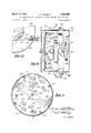
- FIG. 3 is a view diagrammatically illustrating a possible angular relationship between a drill string supported in a gimbal master bushing on a floating vessel and a length of drill pipe supported by a derrick on the vessel;
- FIG. 4 is a view in horizontal section, as taken on the line 44 of FIG. 3.;
- FIG. 5 is a view corresponding to FIG. 3 but showing the centering means holding the drill string in alignment with the drill pipe supported in the derrick;
- FIG. 6 is a view in horizontal section, as taken on the line 66 of FIG. 5;
- FIG. 7 is a fragmentary view in horizontal section but showing in top plan the pipe centering apparatus of the invention as taken on the line 7-7 of FIG. 2b, depicting an alternate arrangement of the centering means;
- FIG. 8 is a view in vertical section, as taken on the line 88 of FIG. 7;
- FIG. 9 is a view on an enlarged scale in vertical section, as taken on the line 99 of FIG. 8, with certain of the parts shown in elevation and more particularly illustrating a control switch mechanism for regulating the extent of closing movement of the pipe centering means;
- FIG. 10 is an enlarged fragmentary view, partly in vertical section and partly in elevation, as taken on the line 1010 of FIG. 9;
- FIG. 11 is a view in vertical section, as taken on the line 11-11 of FIG. 9;
- FIGS. 12a and 12b together constitute a schematic illustration of the hydraulic control circuitry for the centering means, FIG. 12b being a downward continuation of FIG. 12a;
- FIGS. 13a and 13b together constitute a schematic wiring diagram of the control circuitry for the centering apparatus, FIG. 13b being a downward continuation of FIG. 13a;
- FIG. 14 is a plan view illustrating a selector switch and actuator for selecting the size of pipe for which the centering means is to be set.
- FIG. 1 there is shown a vessel 21 afloat in the water, the surface of the water being designated 22.
- the vessel 21 has a platform 23 located substantially amidships and on which is erected a derrick 24. Extending through the vessel below the platform 23 is an opening defined by a housing 25, such opening generally being referred to in the industry as a moon hole.
- a well drilling string 26 composed of a number of lengths of drill pipe extends downwardly through the moon hole 25 to the bottom of the body of water. In the type of drilling operations performed from floating vessels the drill string 26 will extend downwardly through the usual surface equipment which is located at the bottom of the body of water, including the usual blowout preventer and the like.
- a conductor pipe 10 extends upwardly from the bottom of the body of water and into the moon hole in surrounding relation to the drill string 26 so as to provide an annular space 11 for the return flow of well drilling fluids or mud, the conductor pipe 10 having an outlet 12 leading from the annular space 11 to suitable mud tanks (not shown).
- the derrick 24 has the usual corner posts 27 and 28 supported on the platform 23 on base members 29 and 31.
- a water table 32 near the top of the derrick carries the usual crown block 33 which is aligned with the vertical center line of the derrick.
- cable 34 Suspended from the crown block by cable 34 is a traveling block 35.
- the dead end (not shown) of the cable 34 is anchored to the vessels structure or to the platform, and the other end is led to the drum 36 of a draw works 37 for raising and lowering the traveling block and the load supported thereby.
- a hook structure 38 is swingably suspended from the bottom of the traveling block 35 by inter-engaged bails 39 on the hook and 41 on the block.
- Elevator links 42 are swingably suspended from ears 43 on the hook structure, and the links have an elevator 44 swingably attached by cars 45 to the lower end of the links 42.
- the general reference numeral 46 denotes apparatus for positioning and guiding the block and hook structure.
- a device for stabilizing the links in accordance with the invention is designated by the general reference numeral 47.
- the general reference numeral 48 designates apparatus for supplying compressed air to the elevator 44 to actuate it.
- a stand 49 of drill pipe is shown as being supported by pipe handling equipment including rackers 51 and 52.
- Other stands 53 of drill pipe and a stand 54 of drill collars are shown at rest in a pipe rack having a finger board 55, a base 56, and an intermediate rack member 57.
- the upper end of the drill string 26 is shown projecting above power tongs 58, slips 59, and the rotary table 61.
- Casing manipulating apparatus is shown at 62.
- a swivel and kelly assembly 63 is disposed in the rat hole 64.
- a horizontal stage 65 Projecting outwardly from the derrick and positioned under the racker 51 is a horizontal stage 65 upon which an operator may stand to adjust or repair the racker.
- a cable 66 actuated by a fluid-powered piston-and-cylinder motor 67 for raising and lowering a component of the racker 52.
- the block and hook structure positioning and guiding apparatus, as well as the apparatus for stabilizing the links as generally referred to above, are more particularly illustrated and described in an application for US. Letters Patent of John W. Turner, Jr., Ser. No. 687,818, entitled Stabilized Pipe Supporting Structure for Drilling Rigs.
- the details of the finger board and rack member 57, as well as the base 56, that is, the pipe racking apparatus and its mode of operation, are more particularly the subject matter of an application for US. Letters Patent of Noal E. Johnson and John W. Turner, In, Ser. No. 687,820, entitled Finger Board and Racker Apparatus.
- the hook structure 38 and its relationship to the elevator 44 that is, the means of conducting elevator operating fluid pressure to the elevator from the hook so as to effect the remote operation of the elevator 44, are more particularly the subject matter of an application for U.S. Letters Patent of Edward I. McFadden, Ser. No. 687,829, entitled Fluid Conductor Means for Hook- Mounted Elevator, now US. Patent No. 3,479,062. Accordingly, the details of the rig assembly, except to the extent necessary to describe the structure and mode of operation of the combined traveling block and hook guiding and positioning means and link stabilizer means of the present invention, will not be further described herein.
- the hook structure generally designated 38 comprises a hook body 38b and a hook 38a having the above-described cars 43 thereon by which the links 42 are suspended.
- the hook body 38b is relatively stationary, that is, is non-rotatable, while the hook 38a is adapted to be rotated from a normal position, as shown in FIG. 2a, to angularly displaced positions during certain of the pipe handling operations.
- the hook body 38b is provided with a manifold 380 for air under pressure supplied through a conduit (not shown), air passing from the manifold 380 through a flexible conductor 38d to the elevator 44 so as to cause opening of the elevator 44 when desired.
- An exemplary air-operated elevator is shown in the patent to Chrisman and Nicolson granted Nov. 23, 1954, Patent No. 2,695,189, from which it will be noted that characteristically such an elevator will be air opened, but automatically closed, upon the forceful movement of a pipe into the open elevator in a lateral direction.
- the pipe racker apparatus indicated at 51 and 52 is adapted to support and move the stand of drill pipe 49 to a position centrally of the derrick 24 and above the rotary table 61 in which the drill string 26 is supported by the slips 59. It will be appreciated that, inasmuch as the vessel 21 floats upon the water, it will be subjected to the waves and caused to pitch and/ or roll, thereby causing the derrick to swing from side to side with the stand 49 of drill pipe supported by the rackers 51 and 52 in a fixed relationship to the derrick 24.
- the pin end 49a at the lower end of the drill pipe stand 49 be stabbed into the box end 26a at the upper end of the drill string 26, with the pin and box in axial alignment to enable the making up of the usual threaded connection therebetween.
- the making of such connections poses no real problem insofar as alignment is concerned, but in the case of floating platforms such as the platform 23 on a floating vessel, the movement of the vessel creates a problem respecting the drill string 26.
- the slips 59 fixedly connect the upper end of the drill string 26 to the derrick 24 the drill string 26 will be caused to bend each time the vessel pitches or rolls.
- the gimbal master bushing G comprises a gimbal support or bowl 100 providing a hemispherical seat 101 for the gimbal member 102 which supports the pipe engaging slips 59.
- the gimbal mount 100 is pinned, as at 103, or otherwise suitably connected for rotation with the usual rotary table 61.
- pipe centering apparatus in order to maintain alignment of the pin end 49a and the box end 26a of the drill pipe stand 49 and the drill string 26, respectively, notwithstanding the pitch and roll of the vessel 21, pipe centering apparatus is provided, such apparatus being located beneath the platform 23 and being generally denoted at C.
- the centering apparatus includes a number of spaced pads or bars forming a quadrilateral opening 105 therebetween through which the drill string 26 extends.
- the quadrilateral opening 105 is formed by elongated pads 107, 108, 109 and 110.
- the pads 108 and 110 are disposed on a plane above the pads 107 and 109 so as to allow movement of the pads toward one another, as shown in FIG. 6, so as to grip the drill string 26 between the pads.
- Actuator means are provided for shifting the pads 107-110 in the generally illustrated form of hydraulic ram means 107R, 108R, 109R and 110R respectively connected to the pads 107-110 by rods 111, 112, 113 and 114.
- Suitable means hereinafter to be described are provided for supplying hydraulic fluid under pressure to the respective rams 107R-110R and exhausting fluid therefrom so as to move the pads toward and away from one another.
- the quadrilateral opening 105 is located beneath and in axial alignment with the center of the gimbal mount 100 of the master bushing G. Therefore, the disposition of the upper end of the drill string 26 relative to the platform 23 is fixed, as shown in FIG. 5.
- the centering apparatus includes structure best illustrated in FIGS. 7 through 11. More particularly, the centering apparatus C includes a supporting frame structure adapted to be suitably mounted beneath the platform 23 and including frame members 121 and 122 which define a. central opening 123, this central opening being located beneath the rotary table 61 for the passage of the drill string 26 therethrough.
- the ram means 107R for effecting actuation of the centering pad 107 includes a pair of double acting ram. cylinders 124 suitably rigidly supported on spaced supporting plates 125 formed as part of the frame structure 120 and having actuator rods 111 projecting therefrom and connected at 127 to the ends of the centering pad 107.
- the ram means 108R for actuating the centering pad 108 includes a pair of spaced ram actuator cylinders 128 having actuator rods 112 projecting therefrom and connected as at 130 to the ends of the. centering pad 108. These actuator cylinders 128, as seen in FIGS. 3-6 and in FIGS.
- the actuator means 109R for actuating the centering pad 109 includes a pair of actuator cylinders 132 having rods 113 connected as at 134 to the ends of the centering pad 109, the actuator cylinders 132 being rigidly supported on suitable plates 135 carried by the frame structure 120.
- the ram means 110R for the centering pad 110 includes a pair of actuator cylinders 136 mounted on plates 137 formed as a part of the support structure 120. These actuator cylinders 136 have actuator rods 114 projecting therefrom and connected as at 139 to the ends of the centering pad 110.
- the actuator cylinders 136 are in the plane of the actuator cylinders 128 so that, like the centering pad 108, the centering pad 110' is elevated above the centering pads 107 and 109.
- the actuator cylinders of the ram means 107R-110R may be variously arranged to either push or pull the pads 107-110 toward one another, as may be required by various space limitations.
- all of the actuator cylinders 124, 132 and 136 push the pads 107, 109, 110, but the actuator cylinders 128 are adapted to pull the pad 108 to a closed position.
- all of the ram means 107R- 110R are shown as being adapted to push the pads 107- 110 to their pipe engaging positions.
- the centering pads 107 and 108 constitute a pair which are actuatable in response to the application of fluid under pressure to the respective actuator cylinders 124 and 128 so as to be projected and retracted in unison.
- the centering pads 109 and 110 constitute a pair of pads actuatable by the application of fluid pressure to the actuator cylinders 132 and 136, respectively.
- Position controller means are provided for limiting the movement of the respective pairs of pads relatively toward and away from one another; that is, movement of the pads toward one another is limited to a position at which there is defined an opening therebetween of a selected size, and movement of the pads away from one another is limited so that the pads will retract to a uniform starting position for subsequent projection thereof into engagement with the drill string 26.
- the position controlling means includes in respect of each associated pair of centering pads a position controller, these position controllers being respectively designated PC1 and PC2.
- the position controller PC1 is adapted to control the projection and retraction of the centering pads 107 and 108 by the ram means 107R and 108R
- the position controller PC2 is adapted to control the projection and retraction of the centering pads 109 and 110 by the ram means 109R and 110R.
- FIGS. 9-11 An exemplary position controller is illustrated in FIGS. 9-11.
- This position controller PC1 includes a housing 140 composed of housing sections 141 and 142 suitably attached to an outer flange 143 of a support member 144, the flange 143 having suitable means, such as bolt openings 145, enabling its rigid attachment to a suitable location on the support structure 120.
- a shaft 146 Within the housing 140 is a shaft 146, the shaft projecting into the housing section 141 and having thereon a reel 147 about which is wound a cable 148.
- the cable 148 extends through a suit able packing gland 149 (FIG. so as to prevent the en try of foreign matter into the housing; and at its outer extremity the cable 148 is connected as by an eye 150 to the centering pad 107.
- a re-wind spring means 151 adapted to normally effect revolution of the shaft 146 so as to pull cable 148 into the housing in response to winding of the cable 148 about the reel 147.
- a switch actuator arm 153 Suitably aflixed to the shaft 146 for rotation therewith is a switch actuator arm 153 which will be caused to move angularly about the axis of the shaft 146 a distance which is proportional to the extent of projection of the centering pad 107 by the ram means 107R.
- Supported in spaced relation to the support member 144 on suitable spacers 154 is a switch supporting plate 155 having mounted thereon a number of limit switches respectively designated, as best seen in FIG. 11, LS1 through L510.
- limit switches LS1 through LS10 may be conventional microswitches adapted to be successively actuated by switch actuators 156 which are arranged in radially spaced relation along the switch actuator arm 153 so as to be successively moved into positions for actuating the limit switches LS1 through LS9 in succession upon rotation of the shaft 146 in a counterclockwise direction, as viewed in FIG. 11, one of the limit switch actuators 156 being adapted to actuate the limit switch LS10 in response to rotation of the shaft 146 in a clockwise direction, as viewed in FIG. 11.
- limit switch LS1 it is the purpose of the limit switch LS1 to limit the projected position of the centering pads 107 and 108 to a location adapted to form two sides of the quadrilateral drill string receiving opening, whereby to engage a pipe string of the maximum diameter for which the apparatus is to be used.
- the limit switch LS9 is adapted to limit the inward projection of the centering pads 107 and 108 to position forming two sides of the quadrilateral opening for the pipe string of the smallest diameter for which the subject apparatus is useful.
- the position controller PC1 will suflice to also disclose the details of the second position controller PC2 which is adapted to limit the inward projection of the other pair of pads 109 and which form the other two sides of the quadrilateral pipe string receiving opening.
- the position controller PC2 will be provided with, for example, nine limit switches for limiting the projection of the centering pads 109 and 110 to different extents dependent upon the diameter of the pipe string, as well as with a tenth limit switch which will limit the retraction of the centering pads 109 and 110.
- Means are provided for effecting the simultaneous projection of the centering pads 107 through 110 by their respective ram means 107R through 110R by the application of equal volumes of hydraulic fluid under pressure to the respective actuator cylinders 124, 128, 132 and 136.
- the hydraulic system for actuating the cylinders 124 and 128 of the ram means 107R and 108R is illustrated as including a pump P1 having an inlet leading from a suitable reservoir of hydraulic fluid.
- a conduit 160 leads to solenoid actuated valve means SV-l.
- This valve means SV1 has a return outlet 161 leading back to the reservoir.
- a conduit 162 which is connected to a flow divider 163 which communicates through one outlet conduit 164 with a second flow divider 165 and through a second outlet conduit 166 with a third flow divider 167.
- conduits 168 and 169 respectively lead to the actuator cylinders 128.
- conduits 170 and 171 respectively lead to the actuator cylinders 124.
- fluid is adapted to be supplied to the ram means 107R and 108R to effect equal movement of each of the pads 107 and 108 by the application of equal volumes of fluid to the respective actuator cylinders 124 and 128 acting on the ends of the respective pads 107 and 108 to move the pads in a direction for engagement with a drill string 26.
- the valve means SV-l When the valve means SV-l is actuated to retract the centering pads 107 and 108, fluid will be supplied from the pump P1 to the other ends of the respective actuator cylinders 124 and 128 via a conduit 172 having branch connecttions with each of the actuator cylinders.
- the flow dividers 167, 165 and 163 respectively function as flow accumulators, allowing the uniform exhaust of fluid from the respective actuator cylinders through the exhaust conduit 161 of the valve SV-l.
- a second pump P2 having an inlet from the reservoir and having an outlet conduit 260 leading to solenoid valve means SV2.
- the solenoid valve means SV2 has a return outlet 261 leading back to the reservoir.
- a conduit 262 which is connected to a first flow divider 263, this flow divider communicating through me outlet conduit 264 with a second flow divider 265 and through a second conduit 266 with another flow divider 267. From the flow divider 265 conduits 268 and 269 lead to the actuator cylinders 132.
- conduits 270 and 271 respectively lead to the actuator cylinders 136.
- fluid under pressure is adapted to be supplied to the respective ram means 109R and 110R to effect equal movement of the pads 109 and 110 by the application of equal volumes of fluid to the actuator cylinders 132 and 136 which act on the ends of the pads 109 and 110 to move the pads in a direction for engagement with a drill string 26.
- the solenoid valve means SV2 is actuated to retract the centering pads 109 and 110 fluid will be supplied from the pump P2 to the other ends of the respective actuator cylinders 132 and 136 via a conduit 272 having branch connections with each of the actuator cylinders 132 and 136.
- the flow dividers 263, 265 and 267 respectively act as flow accumulators, allowing the uniform exhaust of fluid from the respective actuator cylinders through the exhaust conduit 261 of the valve SV2.
- each of the solenoid valves SV-l and SV2 is adapted to be actuated to the two positions just described above in response to the energization of a solenoid SOL.A on the one hand, or the energization of a solenoid SOLB on the other hand, whereby to condition the respective valves SV-l and SV2. for the supply of hydraulic fluid to the ram means 107R-110R or the exhaust of such fluid therefrom, the solenoid valves SV-l and SVZ having a normal unrenergized condition at which fluid merely circulates from the pumps P1 and P2 through the valve inlet and exhaust conduits 160, 161 and 260, 261.
- each of the solenoid valves SV1 and SV-Z will have its solenoid A energized when closure of the centering pads 107-110 on the drill string is initiated, and each of these solenoid valves will have its solenoid B energized when the centering pads 107-110 have reached positions determined by the position controllers P01 and P02.
- the hydraulic system as seen in FIG. 12b includes also a pressure relief control system, including a main relief valve 300 which is of the type normally closed by pilot pressure.
- This pressure relief valve 300 includes an inlet 301 which is connected to a conduit 302.
- the conduit 302 leads to a number of ball check valves 303, 304, 305 and 306.
- the check valve 303 communicates through a conduit 307 with the conduit 166 which leads from the flow divider 163 to the flow divider 167 for supplying fluid under pressure to the actuating cylinders 124.
- the check valve 304 communicates through a conduit 308 with the conduit 164 which leads from the flow divider 163 to the flow divider 165 from which fluid is supplied to the actuator cylinders 128.
- the main relief valve will be caused to open and fluid pressure will bleed off through the check valve 303 or through the check valve 304 to an exhaust conduit 309 leading from the main relief valve 300 to the reservoir.
- the check valves 305 and 306 are interconnected between the main relief valve 300 and the flow dividers 265 and 267 which distribute fluid to the cylinders 132 and 136. Accordingly, the check valve 305 communicates through a conduit 310 with the conduit 264 which leads from the flow divider 263 to the flow divider 265 from which fluid is supplied to each of the actuator cylinders 132.
- the check valve 306 communicates through a conduit 311 with the conduit 266 which leads from the flow divider 263 to the flow divider 267 from which fluid is distributed to the actuator cylinders 136.
- selective pilot control means are provided for subjecting the main pressure relief valve 300 to different pilot pressures.
- a pair of solenoid valves SV5 and SV-6 are illustrated for effecting a variation in the pilot pressure supplied to the main pilot controlled relief valve 300 through a pilot conduit 315 by selectively establishing communication between the main relief valve 300 and one of a number of pilot relief valves 316 and 317 controlled by solenoid valve SVS or one of a number of pilot relief valves 318 and 319 controlled by the solenoid valve SV6.
- pilot relief valves 316, 317 and 318, 319 is adapted to open at a particular back pressure applied thereto from the main relief valve 300 through the conduit 315.
- the pilot relief valve 316 will be connected with the conduit 315 of the main relief valve 300 upon energization of the solenoid SOL.A of solenoid valve SV-5 and the pilot relief valve 317 will be connected with the conduit 315 of the main relief valve 300 upon energization of the solenoid SOLB of the solenoid valve SV-5.
- solenoid SOL.A of solenoid valve SV-6 will establish communication between the pilot relief valve 318 and the conduit 315 of the main relief valve 300
- solenoid SOL.B of solenoid valve SV-6 will establish communication between the pilot relief valve 319 and the conduit 315 of the main relief valve 300.
- a relief pilot conduit 320 leads from all of the pilot relief valves 316319 to the conduit 309 and the reservoir.
- the solenoids A and B of both of the solenoid valves SV5 and SV6 are selectively energized when the system is activated to effect the centering of a length of drill pipe or casing by the centering ram means.
- reset means are provided whereby the centering pads 107 through 110 may be retracted by the respective ram means 107R110R beyond their normal retracted positions to what may be characterized as stowed positions of maximum permissible retraction, whereby all of the ram means 107R110R will be reconditioned for effecting subsequent synchronous projection of the centering pads 107-110 toward one another.
- This reset means is seen in FIG. 1211 as including a solenoid valve SV-3 and another solenoid valve SV4 which are connected respectively by conduits 321 and 322 to the exhaust conduits 172 and 272 which lead from the respective actuator cylinders 124, 128 and 132, 136 to the reservoir through the solenoid valves SV1 and SV2. Also included in the reset system are bypass conduits 323 and 324. Conduits 323 is connected to the conduits 168 and 169 through which fluid is exhausted from the actuator cylinders 128 during retraction of the centering pad 108, and conduit 324 is connected to the conduits 170 and 171 through which fluid is exhausted from the actuator cylinders 124 during retraction of the centering pad 107.
- the reset system includes a conduit 327 connected with the exhaust conduits 270 and 271 through which fluid flows from the actuator cylinders 136 during retraction of the centering pad 110; and another conduit is provided at 328 and is connected to the conduits 268 and 269 through which fluid flows from the actuator cylinders 132 when the centering pad 109 is being retracted.
- the conduit 327 is a normally closed, pilot pressure controlled valve 329; and in the conduit 328 is a normally closed, pilot 1 1 pressure controlled valve 330.
- pilot pressure is supplied to the pilot pressure controlled valves 325, 326 and 329, 330 via a pilot pressure conduit 332 which is supplied with fluid from a conduit 333 when the solenoid valves SV3 and SV-4 are opened and when the solenoid B of the solenoid valves SV1 and SV2 are energized to initiate retraction of the centering pads.
- FIGS. 13a and 13b there is illustrated a control circuit diagram whereby the hydraulic systems previously described will be caused to effect actuation of the centering ram and centering pad means as previously described.
- This circuit includes a voltage source which is under the control of a main switch 400 (FIG. 13a).
- This circuit also includes a motor M1 and a motor M2 for respectively driving the pumps P1 and P2 under the control of an on-off switch 401.
- In the motor circuit is a normally open relay contact 403a adapted to be closed upon energization of a relay coil 403 which is in circuit with a Close Rams switch 404.
- an indicator lamp 405 which may be white to indicate that the pump motor circuit is closed as a condition precedent to the closing of the rams upon closure of the Close Rams switch 404.
- the relay coil 403, following closure of the switch 404, is in a holding circuit 405' including another normally open relay contact 403b whereby upon closure of the switch 404 the solenoid A of each of the solenoid valves SVI and SV2 will be energized so as to establish communication between the pumps P1 and P2 and the respective ram actuator cylinders of the ram means 107R-110R.
- the circuitry for effecting closure of the rams may also include an emergency close switch 404 in a circuit which bypasses the holding relay 403.
- An indicator lamp 408 may be included in the ram closing circuit so as to be illuminated when the. rams 107R-110R have effectively closed the centering pads 107110 about the pipe 26.
- the relay coil 411 is illustrated as being coupled at one side of each of the limit switches LS1 through LS9 of the position controller PC1, while the relay coil 412 is illustrated as being coupled at one side of each of the limit switches LS1 through LS9 of the position controller PC2.
- Each of the limit switches LS1 12 through LS9 of both of the position controllers PC1 and PCZ is a normally open switch, one of which is adapted to be selectively placed in the circuit with the relay coils 411 and 412 by means of a suitable selector switch generally denoted at SS.
- the selector switch SS has ten selective positions, respectively designated 81-810, and a rotary selector 415 is provided for selectively placing in parallel a selected one of the limit switches LS1-LS9 of both of the position controllers PC1 and PC2.
- the rotary selector 415 will be placed in contact with the selector switch contact S1 so that each of the limit switches LS1 of the position controllers PC1 and PC2 will be in circuit with the respective relay coils 411 and 412, which relays include respective normally closed contact sets 411a and 412 c coupled in series with the solenoids A of the solenoid valves SV-1 and SV2.
- Rotation of the switch actuator arm 153 (FIG. 11) of the position controllers in a counter-clockwise direction will cause actuation of the micro limit switch LS1 illustrated therein by one of the switch actuators 156.
- the limit switch LS1 of the respective position controller PC1 or PCZ is closed when the pads 107, 108 and the pads 109, have reached their pipe centering position, causing rotation of the switch actuator arm 153 through the flexible cable 148.
- Such closure of the limit switch LS1 of the position controller PC1 will cause energization of the relay coil 411, thereby opening a normally closed relay contact 411b which is in circuit with the holding coil 403 in the Close Rams circuit and, at the same time, the second normally closed relay contact 4110 will be opened, causing de-energization of the solenoid A of the solenoid valve SV-l. The latter valve will then be neutralized and closing motion of the centering pads 107 and 108 will be halted.
- both of the solenoid valves SV-l and SV2 will be neutral, and the centering pads 107-110 will be held in the desired pipe engaging positions until either an Open Rams switch 416 (FIG. 13b) is closed, or the pipe 26, due to the motion of the vessel, is subjected to such a bending force that the relief system previously described allows one of the centering pads 107-110 to move in a direction to relieve the bending force from the pipe 26.
- the open rams circuit is energized by closure of the just-mentioned switch 416 which energizes the holding coil of a relay 417. Energization of the coil relay 417 closes the normally open relay contacts 417a to hold the open rams circuit energized. This energizes the solenoids B of each of the solenoid valves SV-l and SV2 so as to shift these valves to positions reversing the flow of hydraulic fluid to actautor cylinders of the rams means 107R-110R to to retract the centering pads 107-110.
- one of the relay coils 419 or 420 will be energized, causing the opening of one of the contacts 419a or 420a, as well as opening of one of the contacts 41% or 420b,
- the other limit switch LS10 is closed energizing the other of the relays 420 or 419, the other of the contacts 420a or 419a, and 420b or 419a, will be opened, thereby both opening the circuit to the holding relay coil 417 and opening the circuit to the solenoids B of the solenoid valves SV-l and SV-Z.
- the solenoid valves SV-l and SV-2 will be neutralized to limit retraction of the centering pads 107-110 to positions determined by the limit switches LS10, rather than by full retraction of the centering pads.
- An indication that the rams are open may be provided by a rams open indicator light 4220 which is in series circuit with normally open contacts 419s and 420e, which contacts are closed upon energization of the limit switch controlled relays 419 and 420.
- the selector switch SS includes a second set of switch contacts respctively designated S11 through S20; and a rotary contactor 415a is provided for selective engagement with one of the contacts $11-$20.
- certain of the contacts S11- S20 are connected to the solenoid A of solenoid valve SV-S; other of these contacts are connected to the solenoid B of solenoid valve SV; certain of these contacts are connected to the solenoid A of solenoid valve SV6-, and still other of these contacts are connected to the solenoid B of solenoid valve SV-6.
- one of the solenoids A or B of one of the solenoid valves SV-S and SV-6 will be energized so as to establish communication between one of the pilot relief valves 316-319 and the main relief valve pilot conduit 315 as previously described.
- the pressure at which one of the centering pad rarn means 107R-110R will be permitted to be bled off through the main relief valve to the reservoir is determined by the setting of the selector switch SS.
- the circuitry includes a Stow Switch 421 (FIG. 13b) adapted, upon closure thereof, to energize a holding relay coil 422 through normally closed contact set 334a which eifects closure of normally open contacts 422a in a holding circuit through which the solenoids of solenoid valves SV3 and SV-4 are energized.
- Relay coil 422 also closes normally open corrtacts 4221) so as to energize the solenoids B of solenoid valves SV-1 and SV-2 through a circuit parallel to the open ra-ms circuit. Energization of the relay coil 422 moreover effects opening of normally closed contacts 4220 (FIG. 13a) by which the selector 14 switch contacts S11-S20 are connected in the circuit with the solenoids A and B of the solenoid valves SV-5 and SV-fi.
- pilot pressure is supplied to the pilot pressure conduit 332, so that when one of the centering pads 107-110 is fully retracted, one of the pilot pressure controlled valves 325, 326 and 329, 330 will be caused to open thereby allowing bleed off of fluid from the other actuator cylinders of the ram means 107R-110R until all of the centering pads 107- 110 are fully retracted, at which time pressure in the fluid supply conduit 333 will increase causing actuation of the pressure switch 334 (FIG.
- normally closed contacts 428k are interposed between the source of power and the A solenoids of each of the solenoid valves SV-l and SV-2, these normally closed contacts 428k being opened in response to energization of the relief warning relay coil 428 which is energized upon actuation of the pressure switch 334 to close contact set 334b during the relief of fluid from the ram closing hydraulic system.
- an emergency stow circuit may be provided, including an Emer. Stow switch 421a which bypasses the normally open contacts 422b which are under the control of the Stow Switch controlled relay 422.
- the selector switch SS is generally illustrated as having ten selective positions of the rotary selector 415, the positions being provided with legends representative of different sizes of pipe of different types, i.e., drill pipe, drill collars and casing, all of which are referred to herein as pipe inasmuch as they are tubular conduits adapted to be supported in the pipe rackers 51 and 52 in a position above the upper end of a string of such pipe supported in the gimbal master bushing G, as previously described. While there are ten selective positions illustrated for ten sizes of different pipes, it is notable that two of the positions have corresponding pipe sizes, namely, 5" casing and 5" drill pipe.
- the contacts S5 and S9 of the selector switch SS are both connected to the same limit switch LS7 in the schematic diagram, since that single limit switch will function in both cases to limit closure of the centering pads on either drill pipe or casing.
- the string of pipe 26 will be supported in the gimbal master bushing G, as seen in FIG. 3, with the centering pads 107-110 retracted so as to allow angular motion of the derrick 24 relative to the pipe string 26 as a result of pitch or roll of the vessel.
- the length of drill pipe 49 having the pin end 49a at its lower end is supported in the pipe rackers 51 and 52, as shown in FIG. 2b, in a position at which ideally it will be axially aligned with the gimbal master bushing G so as to allow the pin end 49a to be stabbed into the box end 26a of the pipe string 26 supported in the master bushing.
- the centering ram apparatus will be energized by closure of the main switch 400 and conditioning of the pump motors M1 and M2 by closure of the pump on-off switch 401. Thereupon, closure of the centering pads 107110 on the pipe string 26, as seen in FIG. 5, will be effected upon closure of the Close Rams switch 404. As previously described, the position controllers PC1 and PC2 will limit movement of the centering pads toward one another so that the quadrilateral opening defined therebetween is adapted to confine the pipe string 26, as seen in FIG. 6.
- the previously described reset means will be employed by closure of the Stow Switch 421, so that all of the centering pads are retracted to the fullest possible extent, which is a distance greater than normal retraction of the centering pads resulting from energization of the open rams means by closure of the Open Rams switch 416. Accordingly, thereafter when the Close Rams switch 404 is again closed to project the centering pads into engagement with the pipe string 26 the pads will have a uniform starting location and will move in synchronism into centering engagement with the pipe string 26 under the control of the position controllers PC1 and PC2.
- the reset means may also be periodically operated to eliminate any erratic positioning of the pads 107-110 which may be caused by unequal distribuiton of hydraulic fluid to the actuator cylinders of the ram means 107R-110R.
- the length of pipe 49a may be stabbed into the pipe string 26, and the tong means 58 may be employed to effect rotation of the pipe stand 49 to make up the threaded connection thereof with the pipe string 26.
- the Open Rams switch 416 is closed to effect retraction of the centering pads as the now elongated pipe string 26 is lowered into the well by the cable supported traveling block 35 and hook 38.
- the swivel and kelly 63 may be made up with the pipe string 26 and lowered into the gimbal master bushing G so as to be driven rotatably thereby upon rotation of the rotary table 61; and the gimbal master bushing will allow angular disposition of the kelly relative to the axis of the rotary table, so as to relieve the drill string from bending during drilling of the well.
- a well drilling rig comprising, in combination, a vessel adapted to float on a body of water, said vessel having a derrick, a rotary table and a gimbal master bushing for supporting a vertically oriented pipe string at its upper end with said pipe string extending downwardly in the body of water from said vessel, means operatively related with said derrick for supporting a length of pipe in said derrick for connection to said upper end of said pipe string, and centering means spaced from said bushing and operatively related with said rig and engageable with and disengageable from said pipe string for holding said upper end of said pipe string in axial alignment with said length of pipe with said master bushing and said rotary table coaxially disposed with respect to one another for releasing said upper end of said pipe string, and operating means operatively related to said centering means for actuating said centering means into and from engagement with said pipe string, whereby said centering means is engageable with said pipe string during connection of said length of pipe to said pipe string and said centering means is disengageable from
- centering means comprises a number of horizontally extended pads defining a multi-lateral opening through which said upper end of said pipe string extends, and said operating means including means for moving said centering pads towards and away from one another to engage said upper end of said pipe string therebetween for respectively preventing and allowing angular movement of said vessel relative to said upper end of said pipe string.
- said centering means comprises a number of horizontally extended pads defining a multi-lateral opening through which said upper end of said pipe string extends, said operating means including means for projecting said pads towards one another to hold said upper end of said pipe string therebetween, and relief means for allowing one of said pads to retract relative to the other of said pads when said upper end of said pipe string imposes a predetermined force on said one of said pads.
- said centering means comprises a number of horizontally extended pads defining a multi-lateral opening through which said upper end of said pipe string extends, said operating means including means for projecting said pads towards one another to hold said upper end of said pipe string therebetween, relief means for allowing one of said pads to retract relative to the other of said pads when said upper end of said pipe string imposes a predetermined force on said one of said pads, and means for resetting said one of said pads in a uniform spaced relation to the other of said pads following retraction of said one of said pads.
- centering means comprises a plurality of elongated pads defining a multi-lateral opening therebetween, said operating means including ram means for effecting projection and retraction of said pads and position controller means for adjustably limiting said projection of said pads to accommodate pipe strings of different sizes.
- centering means comprises a plurality of elongated centering pads defining a quadrilateral opening therebetween, and said operating means including ram means for effecting projection and retraction of said pads including a pair of rams respectively connected to the ends of each of said pads.
- said centering means comprises a plurality of elongated centering pads defining a quadrilateral opening there- 17 between, said operating means including ram means for effecting projection and retraction of said pads including a pair of rams respectively connected to the ends of each of said pads, and means for supplying equal volumes of hydraulic fluid under pressure to said pairs of rams to effect synchronized projection thereof.
- said centering means comprises a plurality of elongated centering pads defining a quadrilateral opening therebetween, said operating means including ram means for effecting projection and retraction of said pads including a pair of rams respectively connected to the ends of each of said pads, means for supplying equal volumes of hydraulic fluid under pressure to said pairs of rams to effect synchronized projection thereof, and means for resetting the position of said centering pads when one of said pads is out of synchronization with the rest of said pads.
- Pipe centering apparatus for a Well drilling rig on floating vessels, said rig having a rotary table, a gimbal master bushing for a string of pipe extending through the rotary table of said rig, said pipe centering apparatus comprising: a support structure adapted to be connected to said rig and spaced from said gimbal master bushing, and centering means carried by said support structure and actuatable to engage said pipe string and center the latter with respect to said rotary table and to hold said master bushing and rotary table coaxially disposed with respect to one another and to release said pipe string for universal movement with said master bushing.
- Pipe centering apparatus as defined in claim 10, wherein said centering means comprises a plurality of centering pads for defining a quadrilateral opening beneath said rotary table, ram means connected to said support structure and connected to said centering pads for effecting projection and retraction of said centering pads, and means communicating with said ram means for supplying fluid pressure to said ram means.
- centering means comprises a plurality of centering pads for defining a quadrilateral opening beneath said rotary table, ram means connected to said support structure and connected to said centering pads, and including means communicating with said ram means for supplying equal volumes of hydraulic fluid under pressure to said ram means for effecting uniform projection thereof.
- Pipe centering apparatus as defined in claim 10, wherein said centering means comprises a plurality of centering pads for defining a quadrilateral opening beneath said rotary table, ram means connected to said support structure and connected to said centering pads, and including means communicating with said ram means for supplying equal volumes of hydraulic fluid under pressure to said ram means for effecting uniform projection thereof, and position control means operatively related to said ram means for adjustably limiting projection of said pads for centering pipe of different sizes.
- said centering means comprises a plurality of centering pads for defining a quadrilateral opening beneath said rotary table, ram means connected to said support structure and connected to said centering pads, and including means communicating with said ram means for supplying equal volumes of hydraulic fluid under pressure to said ram means for effecting uniform projection thereof, and position control means operatively related to said ram means for adjustably limiting projection of said pads for centering pipe of different sizes, said position control means including means for effecting uniform retraction of said pads.
- said centering means comprises a plurality of centering pads for defining a quadrilateral opening beneath said rotary table, ram means connected to said support structure and connected to said centering pads, and including means communicating with said ram means for supplying hydraulic fluid under pressure to said ram means for effecting projection thereof, said means for supplying hydraulic fluid to said ram means including relief means for bleeding off fluid from the ram means of one of said pads in response to resistance encountered by said last-mentioned ram means.
- said centering means comprises a plurality of centering pads for defining a quadrilateral opening be neath said rotary table, ram means connected to said support structure and connected to said centering pads, and including means communicating with said ram means for supplying hydraulic fluid under pressure to said ram means for effecting projection thereof, said means for supplying hydraulic fluid to said ram means including relief means for bleeding off fluid from the ram means of one of said pads in response to resistance encountered by said last-mentioned ram means, and means operatively related to said ram means for resetting said ram means with said pads in uniform positions.
- said centering means comprises a plurality of elongated centering pads for defining a quadrilateral opening beneath said rotary table, ram means connected to said support structure and connected to each of said centering pads, and including a pair of hydraulic actuators connected to the ends of each of said pads, means communicating with said ram means for supplying equal volumes of hydraulic fluid under pressure toeach of said actuators for effecting uniform projection thereof.
- said centering means comprises a plurality of elongated centering pads for defining a quadrilateral opening beneath said rotary table, pairs of hydraulic actuators respectively connected to the ends of each of said centering pads, means communicating with each of said pairs of hydraulic actuators for supplying hydraulic fluid under pressure to said pairs of hydraulic actuators including flow divider means for supplying equal volumes of hydraulic fluid to each actuator of each of said pairs of actuators.
- said means for supplying hydraulic fluid under pressure to said actuators includes a source of fluid under pressure, conduit means leading from said source to the actuators of a pair of said pads, conduit means leading from said source to the actuators of the other pair of said pads, said flow divider means being in the respective conduit means, valve means in each of said conduit means for controlling the admission of fluid to and the exhaust from the actuators of each of said pairs of pads, and position control means responsive to the position of one of said pads of each of said pair of pads for actuating said valve means to limit projection of said pads.
- said position control means includes a plurality of limit switches, means connected to said one of said pads of each of said pair of pads and operatively related to said limit switches for actuating said limit switches, solenoid means for actuating said valve means, and circuit means for selectively connecting said solenoid means to said limit switches.
- said position control means includes a plurality of limit switches, means connected to said one of said pads of each of said pair of pads and operatively related to said limit switches for actuating said limit switches, solenoid means for actuating said valve means, circuit means for selectively connecting said solenoid means to said limit switches, and including pressure relief means for venting the pair of actuators of one of said pads when said one of said pads encounters a predetermined resistance.
- said position control means includes a plurality of limit switches, means connected to said one of said pads of each of said pair of pads and operatively related to said limit switches for actuating said limit switches, solenoid means for actuating said valve means, circuit means for selectively connecting said solenoid means to said limit switches, and including pressure relief means for venting the pair of actuators of one of said pads when said one of said pads encounters a predetermined resistance, said pressure relief means including a plurality of pilot relief valves, a main relief valve, conduit means connecting said pilot relief valves to said main relief valve, selectively operable valve means in said conduit means between said relief valves for establishing communication between one of said pilot relief valves and said main relief valve, conduit means leading from each of said pairs of actuators to said main relief valve, solenoid means for operating said selectively operable valve means, and selective circuit means for energizing said solenoid means.
- said position control means includes a plurality of limit switches, means connected to said one of said pads of each of said pair of pads and operatively related to said limit switches for actuating said limit switches, solenoid means for actuating said valve means, circuit means for selectively connecting said solenoid means to said limit switches, and including reset means for effecting retraction of all of said centering pads to uniform positions.
- Pipe centering apparatus as defined in claim 10, wherein said centering means comprises a plurality of pipe engaging elements for defining an opening beneath said rotary table, hydraulic actuators connected to said elements, and means communicating with said hydraulic actuators for supplying hydraulic fluid under pressure to said actuators.
- Pipe centering apparatus as defined in claim 24, wherein said means communicating with said hydraulic actuators for supplying hydraulic fluid under pressure to said actuators includes a source of fluid under pressure, conduit means leading from said source to said actuators, valve means in said conduit means for controlling the admission of fluid to and the exhaust of fluid from said actuators, and position control means responsive to the position of said elements and operatively associated with said valve means for actuating said valve means to limit movement of said elements towards one another.
- Pipe centering apparatus as defined in claim 25, wherein said position control means includes a plurality of limit switches, means connected to certain of said elements for actuating said limit switches, solenoid means for actuating said valve means, and circuit means for selectively connecting said solenoid means to said limit switches.
- Pipe centering apparatus as defined in claim 25, wherein said position control means includes a support, a plurality of limit switches spaced angularly on said support, a shaft revolvable on said support and having limit switch operator means thereon, and means connecting said shaft to one of said elements for actuating said switch operator upon movement of said elements toward and away from one another, said means connecting one of said elements to said shaft including a flexible cable and a reel carried by said shaft, said cable being wound on said reel.
- said position control means includes a support, a plurality of limit switches spaced angularly on said support, a shaft revolvable on said support and having limit switch operator means thereon, and means connecting said shaft to one of said elements for actuating said switch operator upon movement of said elements toward and away from one another, said means connecting one of said elements to said shaft including a flexible cable and a reel carried by said shaft, said cable being wound on said reel, and including spring re-wind means for winding said cable on said reel upon movement of said elements away from one another.
Description
March 31, 1970 J. F. GADBOIS 3,
PIPE HANDLING AND CENTERING APPARATUS FOR WELL DRILLING R165 9 Sheets-Sheet 1 Filed July 5, 1968 INVENTOR JQH/V PEA/v05 6,4050/5 BY 6 f March 1970 I .1. F. GADBOIS 3,503,460
PIPE HANDLING AND CENTERING APPARATUS FOR WELL DRILLING RIGS Filed July 5, 1968 9 Sheets-Sheet 2 aad W42 a 27 v Q a; E25 57 5/ u T w m. 22,.
INVENTOR J0/7 A/F64A/C/5 64050/5 I mad/$2 2 ATTOEA/EV March 31, 1970 J F. GADBOIS 3,503,460
PIPE HANDLING AND CENTERING APPARATUS FOR WELL DRILLING RIGS Filed July 5, 1968 9 Sheets-Sheet 5 49 M o M52 4% W 4 m5 o I O O V i o 7 K V o we j/a w 1/09? a 62 .i D
INVENTOR. J0/1'A/F54NC75 6/3050/5 Bar f? March 31, 1970 J. F. GADBOIS PIPE HANDLING AND CENTERING APPARATUS FOR WELL DRILLING RIGS Filed July 5. 1968 9 Sheets-Sheet 4.
INVENTOR. JdH/V 1 54/1/05 640506 BY J I A 77'0E/L/6V J SQ Saw b mm March 31, 1970 J. F. GADBOIS 3,503,460
RIPE HANDLING AND CENTERING APPARATUS FOR WELL DRILLING RIGS Filed July 5, 1968 9 Sheets-Sheet 5 5 o INVENTOR.
3% J'0/l/V FEM/d5 6/1050/5 BY W7;
A TTOE/VEJ March 31, 1970 J. F. GADBOIS PIPE HANDLING AND CENTERING APPARATUS FOR WELL DRILLING RIGS 9 Sheets-Sheet 6 Filed July 5, 1968 March 31, 1970 J. F. GADBOIS 3,
PIPE HANDLING AND CENTERING APPARATUS FOR WELL DRILLING RIGS 9 Sheets-Sheet '7 Filed July 5, 1968 March 1970 J. F. GADBOIS 3,503,460
PIPE HANDLING AND CENTERING APPARATUS FOR WELL DRILLING RIGS Filed July 5, 1968 9 Sheets-Sheet 8 #5 1/40. MA/A/ J0///v FZ l/W Armz/va United States Patent 3,503,460 PIPE HANDLING AND CENTERING APPARATUS FOR WELL DRILLING RIGS John F. Gadbois, Houston, Tex., assignor to Byron Jackson Inc., Long Beach, Calif., a corporation of Delaware Filed July 3, 1968, Ser. No. 742,258 Int. Cl. E21b 7/12 U.S. Cl. 175-5 28 Claims ABSTRACT OF THE DISCLOSURE Pipe handling and centering apparatus for well drilling rigs in which a length of pipe is supported by a well drilling derrick mounted on a derrick floor which is movable relative to a length of pipe extending into the well bore and supported in a gimbal master bushing and pipe centering apparatus is employed to engage the length of pipe below the gimbal master bushing to deflect the pipe so as to align the length of pipe supported in the gimbal master bushing with the length of pipe supported in the derrick to facilitate the making up of threaded connections therebetween. Such apparatus in which the pipe centering apparatus includes opposing rams hydraulically actuated to engage and move the length of pipe supported in the gimbal master bushing and in which one of the rams is relieved of hydraulic fluid pressure in the event that the tendency of the derrick to move relative to the length of pipe supported in the gimbal master bushing is excessive.
BACKGROUND OF THE INVENTION In the drilling of offshore wells from a floating barge or vessel which is subject to the effects of wind and waves, problems are encountered in the making up of the threaded connections or tool joints between a length of pipe supported by the well drilling derrick equipment and the upper end of the drill string supported in the master bushing. If the upper end of the drill string supported in the master bushing is held against movement relative to the vessel so as to be forcibly held in a disposition at which the threaded box at the upper end thereof is inherently in axial alignment with a length of drill pipe to be added to the drill string, then the upper end of the drill string which is fixedly engaged in the master bushing is at all times subjected to the effects of movement of the vessel, such as the pitch and roll caused by waves.
Efforts have been made to avoid some of the problems encountered in such well drilling operations involving the use of a floating vessel. For example, vessels have been provided with means for allowing the vessel to be headed into the waves and to move angularly about a stationary midsection of the vessel, thereby minimizing rolling of the vessel. However, such vessels do not eliminate the inherent pitch resulting from the vessels heading into the waves. Fixation of the upper end of the drill string supported in the rotary table mechanism inherently results in bending of the drill pipe not only during the periods of time when connections are being made but at all other times during the drilling operations, thus resulting in potential fatigue failure of the drill pipe.
When the upper end of the drill string is supported in the usual gimbal master bushing which allows the' vessel to pitch or roll relative to the drill pipe, then angular misalignment results between a length of drill pipe supported in the moving derrick and the upper end of the drill string supported in the gimbal master bushing, resulting in difficulties in stabbing the pin end of a length of drill pipe supported in the derrick into the box end of the drill 3,503,460 Patented Mar.- 31, 1970 string supported in the gimbal master bushing and resulting in the tendency of the tool joints to be cross-threaded.
SUMMARY The present invention provides apparatus combined with the structure for supporting a length of drill string in a gimbal master bushing beneath a derrick which supports a length of drill pipe to be added to the drill string sup ported in the gimbal master bushing, which apparatus is adapted to engage and deflect the drill string beneath the gimbal master bushing so as to temporarily bend the same during the period that the tool joint is to be made up, bending of the drill string below the gimbal master bushing resulting in the gimbal master bushing being aligned with the length of drill pipe supported in the derrick.
In accomplishing the foregoing, the invention more particularly provides centering ram apparatus operated by hydraulic fluid under pressure to engage the drill string below the gimbal master bushing and eifectively align the portion of the drill string below the master bushing with the axis of the gimbal mount, so that the drill string projecting upwardly through the gimbal master bushing is aligned with a length of drill pipe supported in the derrick in the same manner as would occur if the master bushing were of the conventional non-gimbaled type which would sup port the upper end of the drill string and inherently maintain coaxial alignment of the master bushing and the drill string at all times. The centering ram means are operated intermittently only when it is desired to make up a length of drill pipe (including the usual kelly) with the drill string supported in the master bushing, so that the drill string is not otherwise subjected to bending during normal drilling operations when the floating vessel tends to pitch and/or roll.
Further, the invention provides centering ram means which are adapted to relieve the bending forces applied to the drill string to force it into alignment with the pipe supported in the derrick in the event that the pitch and/ or roll of the vessel is of such magnitude as to overstress the drill string, resulting otherwise in damage to the drill string and potential failure thereof.
The centering ram apparatus of the invention furthermore is adjustable to accommodate and center pipe in a range of sizes or diameters, say from relatively small drill pipe to relatively large casing. In accomplishing this, selector means are provided for establishing for the centering rams a limit to their movement toward one another in directions adapted to center the pipe therebetween.
The pipe centering means in accordnnce with the invention comprises horizontally extended pads adapted to be moved toward and away from a center line projecting downwardly from the gimbal master bushing by pairs of hydraulic rams supporting the pads at their ends, so that the pads are adapted to engage the pipe at any location along the length of the pads and progressively move the pipe into a central location between the pads as the pads are moved in a closing direction relative to one another, means being provided for distributing the hydraulic fluid from a supply source between each pair of pad operating rams so as to apply equal closing forces to the opposite ends of the respective pads.
The hydraulic distribution system also includes means for periodically permitting the equalization of the ram closing systems so as to prevent movement of one of the centering pads a distance greater than another of the centering pads during the pipe centering operation.
Further objects and advantages of the invention will be herein shown and described or will become apparent to those skilled in the art as defined in the appended claims.
3 BRIEF DESCRIPTION OF THE DRAWINGS FIG. 1 is a side elevational view of a drilling vessel having a derrick assembly and pipe centering apparatus in accordance with the invention;
FIGS. 2a and 2b together constitute an enlarged view of the derrick assembly and the deck portion of the vessel, taken on the line 22 of FIG. 1, FIG. 2b being a downward continuation of FIG. 2a;
FIG. 3 is a view diagrammatically illustrating a possible angular relationship between a drill string supported in a gimbal master bushing on a floating vessel and a length of drill pipe supported by a derrick on the vessel;
FIG. 4 is a view in horizontal section, as taken on the line 44 of FIG. 3.;
FIG. 5 is a view corresponding to FIG. 3 but showing the centering means holding the drill string in alignment with the drill pipe supported in the derrick;
FIG. 6 is a view in horizontal section, as taken on the line 66 of FIG. 5;
FIG. 7 is a fragmentary view in horizontal section but showing in top plan the pipe centering apparatus of the invention as taken on the line 7-7 of FIG. 2b, depicting an alternate arrangement of the centering means;
FIG. 8 is a view in vertical section, as taken on the line 88 of FIG. 7;
FIG. 9 is a view on an enlarged scale in vertical section, as taken on the line 99 of FIG. 8, with certain of the parts shown in elevation and more particularly illustrating a control switch mechanism for regulating the extent of closing movement of the pipe centering means;
FIG. 10 is an enlarged fragmentary view, partly in vertical section and partly in elevation, as taken on the line 1010 of FIG. 9;
FIG. 11 is a view in vertical section, as taken on the line 11-11 of FIG. 9;
FIGS. 12a and 12b together constitute a schematic illustration of the hydraulic control circuitry for the centering means, FIG. 12b being a downward continuation of FIG. 12a;
FIGS. 13a and 13b together constitute a schematic wiring diagram of the control circuitry for the centering apparatus, FIG. 13b being a downward continuation of FIG. 13a;
FIG. 14 is a plan view illustrating a selector switch and actuator for selecting the size of pipe for which the centering means is to be set.
DESCRIPTION OF THE PREFERRED EMBODIMENT Referring to FIG. 1, there is shown a vessel 21 afloat in the water, the surface of the water being designated 22. The vessel 21 has a platform 23 located substantially amidships and on which is erected a derrick 24. Extending through the vessel below the platform 23 is an opening defined by a housing 25, such opening generally being referred to in the industry as a moon hole. A well drilling string 26 composed of a number of lengths of drill pipe extends downwardly through the moon hole 25 to the bottom of the body of water. In the type of drilling operations performed from floating vessels the drill string 26 will extend downwardly through the usual surface equipment which is located at the bottom of the body of water, including the usual blowout preventer and the like. A conductor pipe 10 extends upwardly from the bottom of the body of water and into the moon hole in surrounding relation to the drill string 26 so as to provide an annular space 11 for the return flow of well drilling fluids or mud, the conductor pipe 10 having an outlet 12 leading from the annular space 11 to suitable mud tanks (not shown). As best seen in FIGS. 2a and 2b, the derrick 24 has the usual corner posts 27 and 28 supported on the platform 23 on base members 29 and 31. A water table 32 near the top of the derrick carries the usual crown block 33 which is aligned with the vertical center line of the derrick. Suspended from the crown block by cable 34 is a traveling block 35. As is usual, the dead end (not shown) of the cable 34 is anchored to the vessels structure or to the platform, and the other end is led to the drum 36 of a draw works 37 for raising and lowering the traveling block and the load supported thereby.
A hook structure 38 is swingably suspended from the bottom of the traveling block 35 by inter-engaged bails 39 on the hook and 41 on the block. Elevator links 42, only one of which is seen in FIGS. 2a and 2b, are swingably suspended from ears 43 on the hook structure, and the links have an elevator 44 swingably attached by cars 45 to the lower end of the links 42.
The general reference numeral 46 denotes apparatus for positioning and guiding the block and hook structure. A device for stabilizing the links in accordance with the invention is designated by the general reference numeral 47. The general reference numeral 48 designates apparatus for supplying compressed air to the elevator 44 to actuate it.
A stand 49 of drill pipe is shown as being supported by pipe handling equipment including rackers 51 and 52. Other stands 53 of drill pipe and a stand 54 of drill collars are shown at rest in a pipe rack having a finger board 55, a base 56, and an intermediate rack member 57. The upper end of the drill string 26 is shown projecting above power tongs 58, slips 59, and the rotary table 61. Casing manipulating apparatus is shown at 62. A swivel and kelly assembly 63 is disposed in the rat hole 64.
Projecting outwardly from the derrick and positioned under the racker 51 is a horizontal stage 65 upon which an operator may stand to adjust or repair the racker. Associated with the racker 52 is a cable 66 actuated by a fluid-powered piston-and-cylinder motor 67 for raising and lowering a component of the racker 52.
The block and hook structure positioning and guiding apparatus, as well as the apparatus for stabilizing the links as generally referred to above, are more particularly illustrated and described in an application for US. Letters Patent of John W. Turner, Jr., Ser. No. 687,818, entitled Stabilized Pipe Supporting Structure for Drilling Rigs. The details of the finger board and rack member 57, as well as the base 56, that is, the pipe racking apparatus and its mode of operation, are more particularly the subject matter of an application for US. Letters Patent of Noal E. Johnson and John W. Turner, In, Ser. No. 687,820, entitled Finger Board and Racker Apparatus. The hook structure 38 and its relationship to the elevator 44, that is, the means of conducting elevator operating fluid pressure to the elevator from the hook so as to effect the remote operation of the elevator 44, are more particularly the subject matter of an application for U.S. Letters Patent of Edward I. McFadden, Ser. No. 687,829, entitled Fluid Conductor Means for Hook- Mounted Elevator, now US. Patent No. 3,479,062. Accordingly, the details of the rig assembly, except to the extent necessary to describe the structure and mode of operation of the combined traveling block and hook guiding and positioning means and link stabilizer means of the present invention, will not be further described herein.
It will be noted that the hook structure generally designated 38 comprises a hook body 38b and a hook 38a having the above-described cars 43 thereon by which the links 42 are suspended. The hook body 38b is relatively stationary, that is, is non-rotatable, while the hook 38a is adapted to be rotated from a normal position, as shown in FIG. 2a, to angularly displaced positions during certain of the pipe handling operations. Accordingly, the hook body 38b is provided with a manifold 380 for air under pressure supplied through a conduit (not shown), air passing from the manifold 380 through a flexible conductor 38d to the elevator 44 so as to cause opening of the elevator 44 when desired. An exemplary air-operated elevator is shown in the patent to Chrisman and Nicolson granted Nov. 23, 1954, Patent No. 2,695,189, from which it will be noted that characteristically such an elevator will be air opened, but automatically closed, upon the forceful movement of a pipe into the open elevator in a lateral direction.
The pipe racker apparatus indicated at 51 and 52, and more particularly illustrated in an application for US. Letters Patent of John W. Turner, 11:, Ser. No. 731,542 entitled Well Pipe Racker, is adapted to support and move the stand of drill pipe 49 to a position centrally of the derrick 24 and above the rotary table 61 in which the drill string 26 is supported by the slips 59. It will be appreciated that, inasmuch as the vessel 21 floats upon the water, it will be subjected to the waves and caused to pitch and/ or roll, thereby causing the derrick to swing from side to side with the stand 49 of drill pipe supported by the rackers 51 and 52 in a fixed relationship to the derrick 24. However, it is desired that the pin end 49a at the lower end of the drill pipe stand 49 be stabbed into the box end 26a at the upper end of the drill string 26, with the pin and box in axial alignment to enable the making up of the usual threaded connection therebetween. On stable platforms the making of such connections poses no real problem insofar as alignment is concerned, but in the case of floating platforms such as the platform 23 on a floating vessel, the movement of the vessel creates a problem respecting the drill string 26. In this connection, if the slips 59 fixedly connect the upper end of the drill string 26 to the derrick 24 the drill string 26 will be caused to bend each time the vessel pitches or rolls. Such bending of the drill pipe is damaging thereto, particularly during the drilling operations which involve rotation of the drill string 26 by the rotary table 61. Accordingly, in the use of some floating vessels having drilling derricks thereon, gimbal master bushings or drive bushing assemblies for supporting the slips 59 have been employed which, as shown in FIG. 3, allow the drill string 26 to remain vertical 'while the derrick rocks angularly relative to a horoizontal plane. Obviously, the use of such gimbal master bushings, illustrated generally at G in FIG. 3, relieves the drill string from bending during the round-tripping of drill pipe and relieves the kelly from bending during drilling operations. The gimbal master bushing G comprises a gimbal support or bowl 100 providing a hemispherical seat 101 for the gimbal member 102 which supports the pipe engaging slips 59. The gimbal mount 100 is pinned, as at 103, or otherwise suitably connected for rotation with the usual rotary table 61.
While such a gimbal master bushing is protective of the drill string, it enables the pin end 49a of the drill pipe stand 49 supported in the rackers 51 and 52 to be disposed at an angle relative to the box end 26a at the top of the drill string 26 and to be laterally displaced therefrom, thus rendering difficult the operation of stabbing the pin end 49a into the box end 26a to make up the threaded joint when the vessel is being subjected to the action of the waves.
Therefore, in accordance with the invention, in order to maintain alignment of the pin end 49a and the box end 26a of the drill pipe stand 49 and the drill string 26, respectively, notwithstanding the pitch and roll of the vessel 21, pipe centering apparatus is provided, such apparatus being located beneath the platform 23 and being generally denoted at C.
The centering apparatus includes a number of spaced pads or bars forming a quadrilateral opening 105 therebetween through which the drill string 26 extends. As gen erally illustrated in FIGS. 3 through 6, the quadrilateral opening 105 is formed by elongated pads 107, 108, 109 and 110. In the illustrative showing, the pads 108 and 110 are disposed on a plane above the pads 107 and 109 so as to allow movement of the pads toward one another, as shown in FIG. 6, so as to grip the drill string 26 between the pads. Actuator means are provided for shifting the pads 107-110 in the generally illustrated form of hydraulic ram means 107R, 108R, 109R and 110R respectively connected to the pads 107-110 by rods 111, 112, 113 and 114. Suitable means hereinafter to be described are provided for supplying hydraulic fluid under pressure to the respective rams 107R-110R and exhausting fluid therefrom so as to move the pads toward and away from one another. When the pads 107-110 are moved toward one another so as to grip the pipe, the quadrilateral opening 105 is located beneath and in axial alignment with the center of the gimbal mount 100 of the master bushing G. Therefore, the disposition of the upper end of the drill string 26 relative to the platform 23 is fixed, as shown in FIG. 5. Since the disposition of the stand of drill pipe 49 in the derrick 24 is fixed by the racker means 51 and 52 so as to be in axial alignment with the center of the master bushing G, it is now apparent that the pin end 49a of the drill pipe stand 49 and the box end 26a of the drill string 26 will also be in axial alignment so that the pin may be stabbed into the box without regard to the pitch or roll of the vessel, the centering means C effectively causing the drill string 26 to bend below the centering means to compensate for the pitch or roll. How ever, the bending of the drill string 26 occurs only when the centering means is closed upon the drill string and not during drilling operations.
The centering apparatus includes structure best illustrated in FIGS. 7 through 11. More particularly, the centering apparatus C includes a supporting frame structure adapted to be suitably mounted beneath the platform 23 and including frame members 121 and 122 which define a. central opening 123, this central opening being located beneath the rotary table 61 for the passage of the drill string 26 therethrough.
The ram means 107R for effecting actuation of the centering pad 107 includes a pair of double acting ram. cylinders 124 suitably rigidly supported on spaced supporting plates 125 formed as part of the frame structure 120 and having actuator rods 111 projecting therefrom and connected at 127 to the ends of the centering pad 107. The ram means 108R for actuating the centering pad 108 includes a pair of spaced ram actuator cylinders 128 having actuator rods 112 projecting therefrom and connected as at 130 to the ends of the. centering pad 108. These actuator cylinders 128, as seen in FIGS. 3-6 and in FIGS. 7 and 8 in their alternate arrangement for pulling instead of pushing the pad 108, are rigidly supported on suitable plates 131 formed as a part of the support structure 120 so as to extend at right angles to the actuator cylinders 124; and, as illustrated in FIG. 8, it will be seen that the actuator cylinders 128 (shown in phantom lines to indicate their relative vertical positions) are located on a plane vertically spaced above the plane of the actuator cylinders 124 and 132, so that the centering pad 108 is elevated above the plane of the centering pads 107 and 109. The actuator means 109R for actuating the centering pad 109 includes a pair of actuator cylinders 132 having rods 113 connected as at 134 to the ends of the centering pad 109, the actuator cylinders 132 being rigidly supported on suitable plates 135 carried by the frame structure 120. The ram means 110R for the centering pad 110 includes a pair of actuator cylinders 136 mounted on plates 137 formed as a part of the support structure 120. These actuator cylinders 136 have actuator rods 114 projecting therefrom and connected as at 139 to the ends of the centering pad 110. The actuator cylinders 136 are in the plane of the actuator cylinders 128 so that, like the centering pad 108, the centering pad 110' is elevated above the centering pads 107 and 109. Thus movement of the centering pads toward and away from one another is enabled so as to form a quadrilateral opening therebetween for pipe of various diameters. The actuator cylinders of the ram means 107R-110R may be variously arranged to either push or pull the pads 107-110 toward one another, as may be required by various space limitations. Thus, in the illustrative structure of FIGS. 7 and 8 7 all of the actuator cylinders 124, 132 and 136 push the pads 107, 109, 110, but the actuator cylinders 128 are adapted to pull the pad 108 to a closed position. Otherwise, in the illustrations, all of the ram means 107R- 110R are shown as being adapted to push the pads 107- 110 to their pipe engaging positions.
As will hereinafter more fully appear, the centering pads 107 and 108 constitute a pair which are actuatable in response to the application of fluid under pressure to the respective actuator cylinders 124 and 128 so as to be projected and retracted in unison. Likewise, the centering pads 109 and 110 constitute a pair of pads actuatable by the application of fluid pressure to the actuator cylinders 132 and 136, respectively.
Position controller means are provided for limiting the movement of the respective pairs of pads relatively toward and away from one another; that is, movement of the pads toward one another is limited to a position at which there is defined an opening therebetween of a selected size, and movement of the pads away from one another is limited so that the pads will retract to a uniform starting position for subsequent projection thereof into engagement with the drill string 26. The position controlling means includes in respect of each associated pair of centering pads a position controller, these position controllers being respectively designated PC1 and PC2. The position controller PC1 is adapted to control the projection and retraction of the centering pads 107 and 108 by the ram means 107R and 108R, and the position controller PC2 is adapted to control the projection and retraction of the centering pads 109 and 110 by the ram means 109R and 110R.
An exemplary position controller is illustrated in FIGS. 9-11. This position controller PC1 includes a housing 140 composed of housing sections 141 and 142 suitably attached to an outer flange 143 of a support member 144, the flange 143 having suitable means, such as bolt openings 145, enabling its rigid attachment to a suitable location on the support structure 120. Within the housing 140 is a shaft 146, the shaft projecting into the housing section 141 and having thereon a reel 147 about which is wound a cable 148. The cable 148 extends through a suit able packing gland 149 (FIG. so as to prevent the en try of foreign matter into the housing; and at its outer extremity the cable 148 is connected as by an eye 150 to the centering pad 107. Within the housing section 142 of the position controller PC1 is a re-wind spring means 151 adapted to normally effect revolution of the shaft 146 so as to pull cable 148 into the housing in response to winding of the cable 148 about the reel 147. Suitably aflixed to the shaft 146 for rotation therewith is a switch actuator arm 153 which will be caused to move angularly about the axis of the shaft 146 a distance which is proportional to the extent of projection of the centering pad 107 by the ram means 107R. Supported in spaced relation to the support member 144 on suitable spacers 154 is a switch supporting plate 155 having mounted thereon a number of limit switches respectively designated, as best seen in FIG. 11, LS1 through L510. These limit switches LS1 through LS10 may be conventional microswitches adapted to be successively actuated by switch actuators 156 which are arranged in radially spaced relation along the switch actuator arm 153 so as to be successively moved into positions for actuating the limit switches LS1 through LS9 in succession upon rotation of the shaft 146 in a counterclockwise direction, as viewed in FIG. 11, one of the limit switch actuators 156 being adapted to actuate the limit switch LS10 in response to rotation of the shaft 146 in a clockwise direction, as viewed in FIG. 11.
As will hereinafter more particularly appear, it is the purpose of the limit switch LS1 to limit the projected position of the centering pads 107 and 108 to a location adapted to form two sides of the quadrilateral drill string receiving opening, whereby to engage a pipe string of the maximum diameter for which the apparatus is to be used.
correspondingly, the limit switch LS9 is adapted to limit the inward projection of the centering pads 107 and 108 to position forming two sides of the quadrilateral opening for the pipe string of the smallest diameter for which the subject apparatus is useful.
The above description of the position controller PC1 will suflice to also disclose the details of the second position controller PC2 which is adapted to limit the inward projection of the other pair of pads 109 and which form the other two sides of the quadrilateral pipe string receiving opening. Moreover, like the position controller PC1, the position controller PC2 will be provided with, for example, nine limit switches for limiting the projection of the centering pads 109 and 110 to different extents dependent upon the diameter of the pipe string, as well as with a tenth limit switch which will limit the retraction of the centering pads 109 and 110.
Means are provided for effecting the simultaneous projection of the centering pads 107 through 110 by their respective ram means 107R through 110R by the application of equal volumes of hydraulic fluid under pressure to the respective actuator cylinders 124, 128, 132 and 136.
Referring to FIG. 12a, the hydraulic system for actuating the cylinders 124 and 128 of the ram means 107R and 108R is illustrated as including a pump P1 having an inlet leading from a suitable reservoir of hydraulic fluid. From the pump P1 a conduit 160 leads to solenoid actuated valve means SV-l. This valve means SV1 has a return outlet 161 leading back to the reservoir. Also leading from the valve SV-1 is a conduit 162 which is connected to a flow divider 163 which communicates through one outlet conduit 164 with a second flow divider 165 and through a second outlet conduit 166 with a third flow divider 167. From the second flow divider 165 conduits 168 and 169 respectively lead to the actuator cylinders 128. From the third flow divider 167 conduits 170 and 171 respectively lead to the actuator cylinders 124. Thus, fluid is adapted to be supplied to the ram means 107R and 108R to effect equal movement of each of the pads 107 and 108 by the application of equal volumes of fluid to the respective actuator cylinders 124 and 128 acting on the ends of the respective pads 107 and 108 to move the pads in a direction for engagement with a drill string 26. When the valve means SV-l is actuated to retract the centering pads 107 and 108, fluid will be supplied from the pump P1 to the other ends of the respective actuator cylinders 124 and 128 via a conduit 172 having branch connecttions with each of the actuator cylinders. Under these circumstances, the flow dividers 167, 165 and 163 respectively function as flow accumulators, allowing the uniform exhaust of fluid from the respective actuator cylinders through the exhaust conduit 161 of the valve SV-l.
In order to actuate the cylinders 132 and 136 to cause movement of the pads 109 and 110 there is shown a second pump P2 having an inlet from the reservoir and having an outlet conduit 260 leading to solenoid valve means SV2. Like the solenoid valve means SV-l, the solenoid valve means SV2 has a return outlet 261 leading back to the reservoir. Also leading from the valve SV2 is a conduit 262 which is connected to a first flow divider 263, this flow divider communicating through me outlet conduit 264 with a second flow divider 265 and through a second conduit 266 with another flow divider 267. From the flow divider 265 conduits 268 and 269 lead to the actuator cylinders 132. From the flow divider 267 conduits 270 and 271 respectively lead to the actuator cylinders 136. Thus, fluid under pressure is adapted to be supplied to the respective ram means 109R and 110R to effect equal movement of the pads 109 and 110 by the application of equal volumes of fluid to the actuator cylinders 132 and 136 which act on the ends of the pads 109 and 110 to move the pads in a direction for engagement with a drill string 26. When the solenoid valve means SV2 is actuated to retract the centering pads 109 and 110 fluid will be supplied from the pump P2 to the other ends of the respective actuator cylinders 132 and 136 via a conduit 272 having branch connections with each of the actuator cylinders 132 and 136. During retraction of the centering pads 109 and 110 the flow dividers 263, 265 and 267 respectively act as flow accumulators, allowing the uniform exhaust of fluid from the respective actuator cylinders through the exhaust conduit 261 of the valve SV2.
As will be hereinafter more fully described, each of the solenoid valves SV-l and SV2 is adapted to be actuated to the two positions just described above in response to the energization of a solenoid SOL.A on the one hand, or the energization of a solenoid SOLB on the other hand, whereby to condition the respective valves SV-l and SV2. for the supply of hydraulic fluid to the ram means 107R-110R or the exhaust of such fluid therefrom, the solenoid valves SV-l and SVZ having a normal unrenergized condition at which fluid merely circulates from the pumps P1 and P2 through the valve inlet and exhaust conduits 160, 161 and 260, 261. More particularly, each of the solenoid valves SV1 and SV-Z will have its solenoid A energized when closure of the centering pads 107-110 on the drill string is initiated, and each of these solenoid valves will have its solenoid B energized when the centering pads 107-110 have reached positions determined by the position controllers P01 and P02.
However, in the event that as a result of the excessive pitch or roll of the vessel 21 while the centering pads 107-110 are closed about the drill string, or any pair of these centering pads is engaged with the drill string 26 tending to bend the same, it is desirable that the hydraulic pressure acting to force the centering pads into engagement with the drill string be relieved so as to prevent damage to the drill string. Accordingly, the hydraulic system as seen in FIG. 12b includes also a pressure relief control system, including a main relief valve 300 which is of the type normally closed by pilot pressure. This pressure relief valve 300 includes an inlet 301 which is connected to a conduit 302. The conduit 302 leads to a number of ball check valves 303, 304, 305 and 306. The check valve 303 communicates through a conduit 307 with the conduit 166 which leads from the flow divider 163 to the flow divider 167 for supplying fluid under pressure to the actuating cylinders 124. The check valve 304 communicates through a conduit 308 with the conduit 164 which leads from the flow divider 163 to the flow divider 165 from which fluid is supplied to the actuator cylinders 128. Therefore, if either of the centering pads 107 or 108 is subjected by the drill string 26 to a force resisting movement of the pads 107 and 108, or the maintenance of these pads in engagement with the drill string 26 is suflicient to overstress the drill string 26, the main relief valve will be caused to open and fluid pressure will bleed off through the check valve 303 or through the check valve 304 to an exhaust conduit 309 leading from the main relief valve 300 to the reservoir.
The check valves 305 and 306 are interconnected between the main relief valve 300 and the flow dividers 265 and 267 which distribute fluid to the cylinders 132 and 136. Accordingly, the check valve 305 communicates through a conduit 310 with the conduit 264 which leads from the flow divider 263 to the flow divider 265 from which fluid is supplied to each of the actuator cylinders 132. The check valve 306 communicates through a conduit 311 with the conduit 266 which leads from the flow divider 263 to the flow divider 267 from which fluid is distributed to the actuator cylinders 136. Therefore, if either of the centering pads 109 or .110 is subjected to sufficient force to cause opening of the main relief valve 300, fluid will flow from the flow divider 265 or from the flow divider 267 through the check valves 305 or 306, as the case may be, to the pressure relief outlet conduit 309.
Inasmuch as the maximum holding force to be applied to the pipe string 26 by the centering pads 107-410 varies with the pipe string, that is, varies depending upon the size of the drill pipe or casing engaged between the pads, selective pilot control means are provided for subjecting the main pressure relief valve 300 to different pilot pressures. In the illustrative embodiment, a pair of solenoid valves SV5 and SV-6 are illustrated for effecting a variation in the pilot pressure supplied to the main pilot controlled relief valve 300 through a pilot conduit 315 by selectively establishing communication between the main relief valve 300 and one of a number of pilot relief valves 316 and 317 controlled by solenoid valve SVS or one of a number of pilot relief valves 318 and 319 controlled by the solenoid valve SV6. Each of these pilot relief valves 316, 317 and 318, 319 is adapted to open at a particular back pressure applied thereto from the main relief valve 300 through the conduit 315. Thus, the pilot relief valve 316 will be connected with the conduit 315 of the main relief valve 300 upon energization of the solenoid SOL.A of solenoid valve SV-5 and the pilot relief valve 317 will be connected with the conduit 315 of the main relief valve 300 upon energization of the solenoid SOLB of the solenoid valve SV-5. Correspondingly, energization of the solenoid SOL.A of solenoid valve SV-6 will establish communication between the pilot relief valve 318 and the conduit 315 of the main relief valve 300, and energization of the solenoid SOL.B of solenoid valve SV-6 will establish communication between the pilot relief valve 319 and the conduit 315 of the main relief valve 300. A relief pilot conduit 320 leads from all of the pilot relief valves 316319 to the conduit 309 and the reservoir.
As will hereinafter be described, the solenoids A and B of both of the solenoid valves SV5 and SV6 are selectively energized when the system is activated to effect the centering of a length of drill pipe or casing by the centering ram means.
Inasmuch as some variation in the distribution of hydraulic fluid through the various flow dividers described above may from time to time occur so that the centering pads 107-110 are not actuated in synchronism, reset means are provided whereby the centering pads 107 through 110 may be retracted by the respective ram means 107R110R beyond their normal retracted positions to what may be characterized as stowed positions of maximum permissible retraction, whereby all of the ram means 107R110R will be reconditioned for effecting subsequent synchronous projection of the centering pads 107-110 toward one another.
This reset means is seen in FIG. 1211 as including a solenoid valve SV-3 and another solenoid valve SV4 which are connected respectively by conduits 321 and 322 to the exhaust conduits 172 and 272 which lead from the respective actuator cylinders 124, 128 and 132, 136 to the reservoir through the solenoid valves SV1 and SV2. Also included in the reset system are bypass conduits 323 and 324. Conduits 323 is connected to the conduits 168 and 169 through which fluid is exhausted from the actuator cylinders 128 during retraction of the centering pad 108, and conduit 324 is connected to the conduits 170 and 171 through which fluid is exhausted from the actuator cylinders 124 during retraction of the centering pad 107. In the conduit 323 is a pilot pressure controlled, normally closed valve 325; and in the conduit 324 is a pilot pressure controlled, normally closed valve 326. correspondingly, the reset system includes a conduit 327 connected with the exhaust conduits 270 and 271 through which fluid flows from the actuator cylinders 136 during retraction of the centering pad 110; and another conduit is provided at 328 and is connected to the conduits 268 and 269 through which fluid flows from the actuator cylinders 132 when the centering pad 109 is being retracted. In the conduit 327 is a normally closed, pilot pressure controlled valve 329; and in the conduit 328 is a normally closed, pilot 1 1 pressure controlled valve 330. Through a conduit 331 and suitable branch connections, the respective valves 325, 326 and 329, 330 are adapted to communicate with the reservoir. Pilot pressure is supplied to the pilot pressure controlled valves 325, 326 and 329, 330 via a pilot pressure conduit 332 which is supplied with fluid from a conduit 333 when the solenoid valves SV3 and SV-4 are opened and when the solenoid B of the solenoid valves SV1 and SV2 are energized to initiate retraction of the centering pads. However, when the first of the pads 107- 110 to be fully retracted is prevented from further movement in a retracting direction, pressure in the actuator cylinders of the ram means for that particular centering pad will increase thereby causing an increase in pressure in one of the conduits 321, 322, such increased pressure being applied to the respective pilot pressure controlled valves 325, 326 and 329, 330 whereby to open the latter to thereafter allow the fluid from all of the remaining ram actuator cylinders to bypass the flow dividers 165, 167 and 265, 267 and return to the reservoir through the open valves 325, 326 and 329, 330, respectively. When all of the ram actuator cylinders have effected the full retraction of all of the centering pads 107110 the pressure in the conduits 321, 322 will further increase causing actuation of a pressure switch 334, the purpose of which will be hereinafter more fully described but which serves to de-energize the solenoid valves SV-3 and SV4 to deactivate the reset system. The pads 107-110 are thus, following operation of the reset system, repositioned so as to all have a common starting point, i.e., at the end of their retraction strokes, so that upon the next extension of the actuator cylinders of the ram means 107R-110R the centering pads 107-110 will be moved in synchronism.
Referring now more particularly to FIGS. 13a and 13b, there is illustrated a control circuit diagram whereby the hydraulic systems previously described will be caused to effect actuation of the centering ram and centering pad means as previously described. This circuit includes a voltage source which is under the control of a main switch 400 (FIG. 13a). This circuit also includes a motor M1 and a motor M2 for respectively driving the pumps P1 and P2 under the control of an on-off switch 401. In the motor circuit is a normally open relay contact 403a adapted to be closed upon energization of a relay coil 403 which is in circuit with a Close Rams switch 404. Also in the motor circuit is an indicator lamp 405 which may be white to indicate that the pump motor circuit is closed as a condition precedent to the closing of the rams upon closure of the Close Rams switch 404. The relay coil 403, following closure of the switch 404, is in a holding circuit 405' including another normally open relay contact 403b whereby upon closure of the switch 404 the solenoid A of each of the solenoid valves SVI and SV2 will be energized so as to establish communication between the pumps P1 and P2 and the respective ram actuator cylinders of the ram means 107R-110R. If desired, the circuitry for effecting closure of the rams may also include an emergency close switch 404 in a circuit which bypasses the holding relay 403. An indicator lamp 408 may be included in the ram closing circuit so as to be illuminated when the. rams 107R-110R have effectively closed the centering pads 107110 about the pipe 26. In series with the lamp 408, therefore, are normally open relay contacts 411a and 312a which will be closed to energize the lamp 408 when relay coils 411 and 412 are respectively energized under the control of the position controllers PC1 and PC2, previously referred to, and as shown in a position control circuit including conductors 413 and 414 respectively leading to 'the relay coils 411 and 412 from one of the two source conductors. The relay coil 411 is illustrated as being coupled at one side of each of the limit switches LS1 through LS9 of the position controller PC1, while the relay coil 412 is illustrated as being coupled at one side of each of the limit switches LS1 through LS9 of the position controller PC2. Each of the limit switches LS1 12 through LS9 of both of the position controllers PC1 and PCZ is a normally open switch, one of which is adapted to be selectively placed in the circuit with the relay coils 411 and 412 by means of a suitable selector switch generally denoted at SS.
In the illustrative embodiment the selector switch SS has ten selective positions, respectively designated 81-810, and a rotary selector 415 is provided for selectively placing in parallel a selected one of the limit switches LS1-LS9 of both of the position controllers PC1 and PC2. Accordingly, if the pipe 26 disposed between the centering pads 107-110 is of the largest diameter for which the apparatus is designed, the rotary selector 415 will be placed in contact with the selector switch contact S1 so that each of the limit switches LS1 of the position controllers PC1 and PC2 will be in circuit with the respective relay coils 411 and 412, which relays include respective normally closed contact sets 411a and 412 c coupled in series with the solenoids A of the solenoid valves SV-1 and SV2. Rotation of the switch actuator arm 153 (FIG. 11) of the position controllers in a counter-clockwise direction will cause actuation of the micro limit switch LS1 illustrated therein by one of the switch actuators 156. Thus, the limit switch LS1 of the respective position controller PC1 or PCZ is closed when the pads 107, 108 and the pads 109, have reached their pipe centering position, causing rotation of the switch actuator arm 153 through the flexible cable 148. Such closure of the limit switch LS1 of the position controller PC1 will cause energization of the relay coil 411, thereby opening a normally closed relay contact 411b which is in circuit with the holding coil 403 in the Close Rams circuit and, at the same time, the second normally closed relay contact 4110 will be opened, causing de-energization of the solenoid A of the solenoid valve SV-l. The latter valve will then be neutralized and closing motion of the centering pads 107 and 108 will be halted.
By the same token, when the limit switch LS1 of the position controller P02 is closed in response to the centering pads 109 and 110 reaching the position at which their closing movement is to be arrested, the coil 412 will be energized, thereby opening a first normally closed relay contact 41212 in parallel with contact 41111 and coupled to the holding relay coil 403, and opening the second normally closed relay contact 4120 which is coupled in parallel with contact 4111: and which is in series circuit with the solenoid A of the solenoid valve SV2. When both of the normally closed contacts 411b and 412b are opened in response to energization of both of the relay coils 411 and 412 the circuit to the holding relay coil 403 will be opened. In addition, as will now be apparent, both of the solenoid valves SV-l and SV2 will be neutral, and the centering pads 107-110 will be held in the desired pipe engaging positions until either an Open Rams switch 416 (FIG. 13b) is closed, or the pipe 26, due to the motion of the vessel, is subjected to such a bending force that the relief system previously described allows one of the centering pads 107-110 to move in a direction to relieve the bending force from the pipe 26.
When it is desired to open the rams or move the centering pads 107-110 relatively away from one another, the open rams circuit is energized by closure of the just-mentioned switch 416 which energizes the holding coil of a relay 417. Energization of the coil relay 417 closes the normally open relay contacts 417a to hold the open rams circuit energized. This energizes the solenoids B of each of the solenoid valves SV-l and SV2 so as to shift these valves to positions reversing the flow of hydraulic fluid to actautor cylinders of the rams means 107R-110R to to retract the centering pads 107-110. In circuit with the holding relay coil 417 are normally closed contacts 419a and 420a of a pair of a pair of relays 419 and 420 which are normally de-energized but which are in circuit respectively with the limit switches LS10 of the position controllers PC1 and PC2. In the circuit to the solenoids B of each of the solenoid valves SV-1 and SV-Z are additional normally closed contacts 419]) and 420b which are also adapted to be opened in response to enegization of the relay coils 419 and 420 upon closure of the respective limit switches L810. Thus, when the limit switch LS10 of one of the position controllers PCI and PC2 is closed in response to clockwise movement of the switch actuator arm 153 (FIG. 11) during retraction of the centering pads 107, 108 and 109, 110, respectively, one of the relay coils 419 or 420 will be energized, causing the opening of one of the contacts 419a or 420a, as well as opening of one of the contacts 41% or 420b, When the other limit switch LS10 is closed energizing the other of the relays 420 or 419, the other of the contacts 420a or 419a, and 420b or 419a, will be opened, thereby both opening the circuit to the holding relay coil 417 and opening the circuit to the solenoids B of the solenoid valves SV-l and SV-Z. Thus, the solenoid valves SV-l and SV-2 will be neutralized to limit retraction of the centering pads 107-110 to positions determined by the limit switches LS10, rather than by full retraction of the centering pads. An indication that the rams are open may be provided by a rams open indicator light 4220 which is in series circuit with normally open contacts 419s and 420e, which contacts are closed upon energization of the limit switch controlled relays 419 and 420.
On the other hand, if, prior to the closure of the Open Rams switch 416 one of the centering pads 107-110 is caused to move with the pipe 26 to avoid potential damage to the pipe, as permitted by the previously described pressure relief control system, such pressure relief will be determined by the selection of the setting of the selector switch SS (FIG. 13a) to accommodate various pipe sizes within the opening defined between the centering pads 107410. Accordingly, the selector switch SS includes a second set of switch contacts respctively designated S11 through S20; and a rotary contactor 415a is provided for selective engagement with one of the contacts $11-$20. While Various combinations are feasible, in the illustrated embodiment certain of the contacts S11- S20 are connected to the solenoid A of solenoid valve SV-S; other of these contacts are connected to the solenoid B of solenoid valve SV; certain of these contacts are connected to the solenoid A of solenoid valve SV6-, and still other of these contacts are connected to the solenoid B of solenoid valve SV-6. Accordingly, depending upon the selected setting of the selector switch SS, one of the solenoids A or B of one of the solenoid valves SV-S and SV-6 will be energized so as to establish communication between one of the pilot relief valves 316-319 and the main relief valve pilot conduit 315 as previously described. Thus, the pressure at which one of the centering pad rarn means 107R-110R will be permitted to be bled off through the main relief valve to the reservoir is determined by the setting of the selector switch SS.
Following the relief of fluid from one of the centering rams systems, or at other times when it is desired to synchronize the positions of the centering pads 107-110, the previously described reset system is operated to effect retraction of the pads 107-110 beyond the limit of their retraction determined by the limit switches L510 in the position controllers PCI and PCZ. For this purpose the circuitry includes a Stow Switch 421 (FIG. 13b) adapted, upon closure thereof, to energize a holding relay coil 422 through normally closed contact set 334a which eifects closure of normally open contacts 422a in a holding circuit through which the solenoids of solenoid valves SV3 and SV-4 are energized. Relay coil 422 also closes normally open corrtacts 4221) so as to energize the solenoids B of solenoid valves SV-1 and SV-2 through a circuit parallel to the open ra-ms circuit. Energization of the relay coil 422 moreover effects opening of normally closed contacts 4220 (FIG. 13a) by which the selector 14 switch contacts S11-S20 are connected in the circuit with the solenoids A and B of the solenoid valves SV-5 and SV-fi.
Under these circumstances, with both of the solenoid valves SV3 and SV-4 (FIG. 13b) open, pilot pressure is supplied to the pilot pressure conduit 332, so that when one of the centering pads 107-110 is fully retracted, one of the pilot pressure controlled valves 325, 326 and 329, 330 will be caused to open thereby allowing bleed off of fluid from the other actuator cylinders of the ram means 107R-110R until all of the centering pads 107- 110 are fully retracted, at which time pressure in the fluid supply conduit 333 will increase causing actuation of the pressure switch 334 (FIG. 12b), whereby normally closed contacts 334a will open the circuit to the holding relay coil 422 so that the latter is de-energized, allowing the reopening of normally open relay contacts 422a so that the solenoids of solenoid valves SV-3 and SV-4 are deenergized and the pilot pressure conduit 332 is closed off, the bypass pilot pressure controlled valves 325, 326 and 329, 330 thereby being rendered inoperative.
'Energization of the holding relay coil 422 when the Stow Switch 421 is initially closed opens a set of relay contacts 422d; and energization of the open rams relay coil 417 upon closure of the Open Rams switch 416 opens a set of normally closed contacts 417d whereby to open a relief warning circuit which includes a relay 428 adapted to close a set of normally open contacts 428a when the above-mentioned pressure switch 334 causes the closure of another set of contacts 334b in circuit with the relay coil 428, so as to render operative a relief warning light 430 which may be red to indicate that one of the centering pads 107-110 is being moved in response to the force applied thereto by the pipe 26 to relieve bending force from the pipe. In order to prevent energization of the solenoid valves SV-l and SV-Z (FIG. 13a) to effect closure of the pads 107-110 either by closure of the Close Rams switch 404 or the emergency switch 404', normally closed contacts 428k are interposed between the source of power and the A solenoids of each of the solenoid valves SV-l and SV-2, these normally closed contacts 428k being opened in response to energization of the relief warning relay coil 428 which is energized upon actuation of the pressure switch 334 to close contact set 334b during the relief of fluid from the ram closing hydraulic system.
If desired, an emergency stow circuit may be provided, including an Emer. Stow switch 421a which bypasses the normally open contacts 422b which are under the control of the Stow Switch controlled relay 422.
Referring to FIG. 14, the selector switch SS is generally illustrated as having ten selective positions of the rotary selector 415, the positions being provided with legends representative of different sizes of pipe of different types, i.e., drill pipe, drill collars and casing, all of which are referred to herein as pipe inasmuch as they are tubular conduits adapted to be supported in the pipe rackers 51 and 52 in a position above the upper end of a string of such pipe supported in the gimbal master bushing G, as previously described. While there are ten selective positions illustrated for ten sizes of different pipes, it is notable that two of the positions have corresponding pipe sizes, namely, 5" casing and 5" drill pipe. Thus, the contacts S5 and S9 of the selector switch SS, as illustrated in FIG. 13a, are both connected to the same limit switch LS7 in the schematic diagram, since that single limit switch will function in both cases to limit closure of the centering pads on either drill pipe or casing.
In the use of the apparatus described above, for example, in running a string of drill pipe into a previously drilled hole, the string of pipe 26 will be supported in the gimbal master bushing G, as seen in FIG. 3, with the centering pads 107-110 retracted so as to allow angular motion of the derrick 24 relative to the pipe string 26 as a result of pitch or roll of the vessel. The length of drill pipe 49 having the pin end 49a at its lower end is supported in the pipe rackers 51 and 52, as shown in FIG. 2b, in a position at which ideally it will be axially aligned with the gimbal master bushing G so as to allow the pin end 49a to be stabbed into the box end 26a of the pipe string 26 supported in the master bushing. In the event that the vessel is moving in response to wave action causing angular misalignment, as seen in FIG. 3, then the centering ram apparatus will be energized by closure of the main switch 400 and conditioning of the pump motors M1 and M2 by closure of the pump on-off switch 401. Thereupon, closure of the centering pads 107110 on the pipe string 26, as seen in FIG. 5, will be effected upon closure of the Close Rams switch 404. As previously described, the position controllers PC1 and PC2 will limit movement of the centering pads toward one another so that the quadrilateral opening defined therebetween is adapted to confine the pipe string 26, as seen in FIG. 6. Such closure of the positioning pads upon the pipe string effectively causes alignment of the upper end of the pipe string 26 and the gimbal master bushing G coaxially with respect to the pipe stand 49 supported in the derrick pipe rackers. Under these circumstances, the motion of the vessel is imposed on the pipe string 26 below the centering means C.
If the motion of the vessel is of such magnitude as to do possible damage to the pipe string 26 due to the bending thereof, then the previously described pressure relief means become effective to allow the excessively loaded centering pad to retract so as to relieve the bending of the pipe string 26.
Since such relief of the bending of the pipe by the bleeding off of fluid which causes projection of the rams causes an inherent lack of uniformity in the position of the respective ram actuated centering pads, the previously described reset means will be employed by closure of the Stow Switch 421, so that all of the centering pads are retracted to the fullest possible extent, which is a distance greater than normal retraction of the centering pads resulting from energization of the open rams means by closure of the Open Rams switch 416. Accordingly, thereafter when the Close Rams switch 404 is again closed to project the centering pads into engagement with the pipe string 26 the pads will have a uniform starting location and will move in synchronism into centering engagement with the pipe string 26 under the control of the position controllers PC1 and PC2. The reset means may also be periodically operated to eliminate any erratic positioning of the pads 107-110 which may be caused by unequal distribuiton of hydraulic fluid to the actuator cylinders of the ram means 107R-110R.
With the pipe string 26 centered by the centering means C beneath the master bushing G the length of pipe 49a may be stabbed into the pipe string 26, and the tong means 58 may be employed to effect rotation of the pipe stand 49 to make up the threaded connection thereof with the pipe string 26. Then the Open Rams switch 416 is closed to effect retraction of the centering pads as the now elongated pipe string 26 is lowered into the well by the cable supported traveling block 35 and hook 38. These operations may be repeated until the pipe string, and more particularly a bit (not shown) at the lower end thereof, reaches the bottom of the well. Thereafter, the swivel and kelly 63 may be made up with the pipe string 26 and lowered into the gimbal master bushing G so as to be driven rotatably thereby upon rotation of the rotary table 61; and the gimbal master bushing will allow angular disposition of the kelly relative to the axis of the rotary table, so as to relieve the drill string from bending during drilling of the well.
While the specific details of the invention have been herein shown and described, changes and alterations may be resorted to without departing from the spirit of the invention as defined in the appended claims.
What is claimed is:
1. A well drilling rig comprising, in combination, a vessel adapted to float on a body of water, said vessel having a derrick, a rotary table and a gimbal master bushing for supporting a vertically oriented pipe string at its upper end with said pipe string extending downwardly in the body of water from said vessel, means operatively related with said derrick for supporting a length of pipe in said derrick for connection to said upper end of said pipe string, and centering means spaced from said bushing and operatively related with said rig and engageable with and disengageable from said pipe string for holding said upper end of said pipe string in axial alignment with said length of pipe with said master bushing and said rotary table coaxially disposed with respect to one another for releasing said upper end of said pipe string, and operating means operatively related to said centering means for actuating said centering means into and from engagement with said pipe string, whereby said centering means is engageable with said pipe string during connection of said length of pipe to said pipe string and said centering means is disengageable from said pipe string to free said pipe string and gimbal master bushing after connection of said length of pipe to said pipe string.
2. A well drilling rig as defined in claim 1, wherein said centering means is disposed beneath said rotary table.
3. A well drilling rig as defined in claim 1, wherein said centering means comprises a number of horizontally extended pads defining a multi-lateral opening through which said upper end of said pipe string extends, and said operating means including means for moving said centering pads towards and away from one another to engage said upper end of said pipe string therebetween for respectively preventing and allowing angular movement of said vessel relative to said upper end of said pipe string.
4. A well drilling rig as defined in claim 1, wherein said centering means comprises a number of horizontally extended pads defining a multi-lateral opening through which said upper end of said pipe string extends, said operating means including means for projecting said pads towards one another to hold said upper end of said pipe string therebetween, and relief means for allowing one of said pads to retract relative to the other of said pads when said upper end of said pipe string imposes a predetermined force on said one of said pads.
5. A well drilling rig as defined in claim 1, wherein said centering means comprises a number of horizontally extended pads defining a multi-lateral opening through which said upper end of said pipe string extends, said operating means including means for projecting said pads towards one another to hold said upper end of said pipe string therebetween, relief means for allowing one of said pads to retract relative to the other of said pads when said upper end of said pipe string imposes a predetermined force on said one of said pads, and means for resetting said one of said pads in a uniform spaced relation to the other of said pads following retraction of said one of said pads.
6. A well drilling rig as defined in claim 1, wherein said centering means comprises a plurality of elongated pads defining a multi-lateral opening therebetween, said operating means including ram means for effecting projection and retraction of said pads and position controller means for adjustably limiting said projection of said pads to accommodate pipe strings of different sizes.
7. A well drilling rig as defined in claim 1, wherein said centering means comprises a plurality of elongated centering pads defining a quadrilateral opening therebetween, and said operating means including ram means for effecting projection and retraction of said pads including a pair of rams respectively connected to the ends of each of said pads.
8. A well drilling rig as defined in claim 1, wherein said centering means comprises a plurality of elongated centering pads defining a quadrilateral opening there- 17 between, said operating means including ram means for effecting projection and retraction of said pads including a pair of rams respectively connected to the ends of each of said pads, and means for supplying equal volumes of hydraulic fluid under pressure to said pairs of rams to effect synchronized projection thereof.
9. A well drilling rig as defined in claim 1, wherein said centering means comprises a plurality of elongated centering pads defining a quadrilateral opening therebetween, said operating means including ram means for effecting projection and retraction of said pads including a pair of rams respectively connected to the ends of each of said pads, means for supplying equal volumes of hydraulic fluid under pressure to said pairs of rams to effect synchronized projection thereof, and means for resetting the position of said centering pads when one of said pads is out of synchronization with the rest of said pads.
10. Pipe centering apparatus for a Well drilling rig on floating vessels, said rig having a rotary table, a gimbal master bushing for a string of pipe extending through the rotary table of said rig, said pipe centering apparatus comprising: a support structure adapted to be connected to said rig and spaced from said gimbal master bushing, and centering means carried by said support structure and actuatable to engage said pipe string and center the latter with respect to said rotary table and to hold said master bushing and rotary table coaxially disposed with respect to one another and to release said pipe string for universal movement with said master bushing.
11. Pipe centering apparatus as defined in claim 10, wherein said centering means comprises a plurality of centering pads for defining a quadrilateral opening beneath said rotary table, ram means connected to said support structure and connected to said centering pads for effecting projection and retraction of said centering pads, and means communicating with said ram means for supplying fluid pressure to said ram means.
12. Pipe centering apparatus as defined in claim 10, wherein said centering means comprises a plurality of centering pads for defining a quadrilateral opening beneath said rotary table, ram means connected to said support structure and connected to said centering pads, and including means communicating with said ram means for supplying equal volumes of hydraulic fluid under pressure to said ram means for effecting uniform projection thereof.
13. Pipe centering apparatus as defined in claim 10, wherein said centering means comprises a plurality of centering pads for defining a quadrilateral opening beneath said rotary table, ram means connected to said support structure and connected to said centering pads, and including means communicating with said ram means for supplying equal volumes of hydraulic fluid under pressure to said ram means for effecting uniform projection thereof, and position control means operatively related to said ram means for adjustably limiting projection of said pads for centering pipe of different sizes.
14. Pipe centering apparatus as defined in claim 10, wherein said centering means comprises a plurality of centering pads for defining a quadrilateral opening beneath said rotary table, ram means connected to said support structure and connected to said centering pads, and including means communicating with said ram means for supplying equal volumes of hydraulic fluid under pressure to said ram means for effecting uniform projection thereof, and position control means operatively related to said ram means for adjustably limiting projection of said pads for centering pipe of different sizes, said position control means including means for effecting uniform retraction of said pads.
15. Pipe centering apparatus as defined in claim 10, wherein said centering means comprises a plurality of centering pads for defining a quadrilateral opening beneath said rotary table, ram means connected to said support structure and connected to said centering pads, and including means communicating with said ram means for supplying hydraulic fluid under pressure to said ram means for effecting projection thereof, said means for supplying hydraulic fluid to said ram means including relief means for bleeding off fluid from the ram means of one of said pads in response to resistance encountered by said last-mentioned ram means.
16. Pipe centering apparatus as defined in claim 10, wherein said centering means comprises a plurality of centering pads for defining a quadrilateral opening be neath said rotary table, ram means connected to said support structure and connected to said centering pads, and including means communicating with said ram means for supplying hydraulic fluid under pressure to said ram means for effecting projection thereof, said means for supplying hydraulic fluid to said ram means including relief means for bleeding off fluid from the ram means of one of said pads in response to resistance encountered by said last-mentioned ram means, and means operatively related to said ram means for resetting said ram means with said pads in uniform positions.
17. Pipe centering apparatus as defined in claim 10, wherein said centering means comprises a plurality of elongated centering pads for defining a quadrilateral opening beneath said rotary table, ram means connected to said support structure and connected to each of said centering pads, and including a pair of hydraulic actuators connected to the ends of each of said pads, means communicating with said ram means for supplying equal volumes of hydraulic fluid under pressure toeach of said actuators for effecting uniform projection thereof.
18. Pipe centering apparatus as defined in claim 10, wherein said centering means comprises a plurality of elongated centering pads for defining a quadrilateral opening beneath said rotary table, pairs of hydraulic actuators respectively connected to the ends of each of said centering pads, means communicating with each of said pairs of hydraulic actuators for supplying hydraulic fluid under pressure to said pairs of hydraulic actuators including flow divider means for supplying equal volumes of hydraulic fluid to each actuator of each of said pairs of actuators.
19. Pipe centering apparatus as defined in claim 18, wherein said means for supplying hydraulic fluid under pressure to said actuators includes a source of fluid under pressure, conduit means leading from said source to the actuators of a pair of said pads, conduit means leading from said source to the actuators of the other pair of said pads, said flow divider means being in the respective conduit means, valve means in each of said conduit means for controlling the admission of fluid to and the exhaust from the actuators of each of said pairs of pads, and position control means responsive to the position of one of said pads of each of said pair of pads for actuating said valve means to limit projection of said pads.
20. Pipe centering apparatus as defined in claim 19, wherein said position control means includes a plurality of limit switches, means connected to said one of said pads of each of said pair of pads and operatively related to said limit switches for actuating said limit switches, solenoid means for actuating said valve means, and circuit means for selectively connecting said solenoid means to said limit switches.
21. Pipe centering apparatus as defined in claim 19, wherein said position control means includes a plurality of limit switches, means connected to said one of said pads of each of said pair of pads and operatively related to said limit switches for actuating said limit switches, solenoid means for actuating said valve means, circuit means for selectively connecting said solenoid means to said limit switches, and including pressure relief means for venting the pair of actuators of one of said pads when said one of said pads encounters a predetermined resistance.
22. Pipe centering apparatus as defined in claim 19, wherein said position control means includes a plurality of limit switches, means connected to said one of said pads of each of said pair of pads and operatively related to said limit switches for actuating said limit switches, solenoid means for actuating said valve means, circuit means for selectively connecting said solenoid means to said limit switches, and including pressure relief means for venting the pair of actuators of one of said pads when said one of said pads encounters a predetermined resistance, said pressure relief means including a plurality of pilot relief valves, a main relief valve, conduit means connecting said pilot relief valves to said main relief valve, selectively operable valve means in said conduit means between said relief valves for establishing communication between one of said pilot relief valves and said main relief valve, conduit means leading from each of said pairs of actuators to said main relief valve, solenoid means for operating said selectively operable valve means, and selective circuit means for energizing said solenoid means.
23. Pipe centering apparatus as defined in claim 19, wherein said position control means includes a plurality of limit switches, means connected to said one of said pads of each of said pair of pads and operatively related to said limit switches for actuating said limit switches, solenoid means for actuating said valve means, circuit means for selectively connecting said solenoid means to said limit switches, and including reset means for effecting retraction of all of said centering pads to uniform positions.
24. Pipe centering apparatus as defined in claim 10, wherein said centering means comprises a plurality of pipe engaging elements for defining an opening beneath said rotary table, hydraulic actuators connected to said elements, and means communicating with said hydraulic actuators for supplying hydraulic fluid under pressure to said actuators.
25. Pipe centering apparatus as defined in claim 24, wherein said means communicating with said hydraulic actuators for supplying hydraulic fluid under pressure to said actuators includes a source of fluid under pressure, conduit means leading from said source to said actuators, valve means in said conduit means for controlling the admission of fluid to and the exhaust of fluid from said actuators, and position control means responsive to the position of said elements and operatively associated with said valve means for actuating said valve means to limit movement of said elements towards one another.
26. Pipe centering apparatus as defined in claim 25, wherein said position control means includes a plurality of limit switches, means connected to certain of said elements for actuating said limit switches, solenoid means for actuating said valve means, and circuit means for selectively connecting said solenoid means to said limit switches.
27. Pipe centering apparatus as defined in claim 25, wherein said position control means includes a support, a plurality of limit switches spaced angularly on said support, a shaft revolvable on said support and having limit switch operator means thereon, and means connecting said shaft to one of said elements for actuating said switch operator upon movement of said elements toward and away from one another, said means connecting one of said elements to said shaft including a flexible cable and a reel carried by said shaft, said cable being wound on said reel.
28. Pipe centering apparatus as defined in claim 25, wherein said position control means includes a support, a plurality of limit switches spaced angularly on said support, a shaft revolvable on said support and having limit switch operator means thereon, and means connecting said shaft to one of said elements for actuating said switch operator upon movement of said elements toward and away from one another, said means connecting one of said elements to said shaft including a flexible cable and a reel carried by said shaft, said cable being wound on said reel, and including spring re-wind means for winding said cable on said reel upon movement of said elements away from one another.
References Cited UNITED STATES PATENTS 3,110,350 11/1963 Spiri -5 3,125,171 3/1964 Stewart 175-5 3,142,343 7/1964 Otteman 175--7 3,177,954 4/1965 Rand 175--7 3,310,108 3/1967 Yancey 166.5
NILE O. BYERS, JR., Primary Examiner UNITED STATES PATENT OFFICE CERTIFICATE OF CORRECTION Patent No. 3,5 3, Dat ed March 3 97 Inventor(s) John G iS It is certified that error appears in the above-identified patent and that said Letters Patent are hereby corrected as shown below:
Column 18, line 5 (line 9 of claim 19), after "exhaust" should be --of fluid---.
31 Emblem SEALED Mom ---=m 6 Am Edwardul 'lstclnqil.
Am; Offioor mm x. m.
Oomisaiom of Pat ents Column 8, line +8, "connecttiohs" should be --connections--.
FORM PC4050 410-69) USCOMM-DC wan-P69 0.5. GOVERNMENT PRINTING DFFIC! "GI O-366-3.N
Applications Claiming Priority (1)
| Application Number | Priority Date | Filing Date | Title |
|---|---|---|---|
| US74225868A | 1968-07-03 | 1968-07-03 |
Publications (1)
| Publication Number | Publication Date |
|---|---|
| US3503460A true US3503460A (en) | 1970-03-31 |
Family
ID=24984110
Family Applications (1)
| Application Number | Title | Priority Date | Filing Date |
|---|---|---|---|
| US742258A Expired - Lifetime US3503460A (en) | 1968-07-03 | 1968-07-03 | Pipe handling and centering apparatus for well drilling rigs |
Country Status (7)
| Country | Link |
|---|---|
| US (1) | US3503460A (en) |
| JP (1) | JPS4823241B1 (en) |
| AT (1) | AT292607B (en) |
| DE (1) | DE1933247A1 (en) |
| FR (1) | FR2012257A1 (en) |
| GB (1) | GB1256134A (en) |
| NO (1) | NO128454B (en) |
Cited By (24)
| Publication number | Priority date | Publication date | Assignee | Title |
|---|---|---|---|---|
| US3650339A (en) * | 1969-09-15 | 1972-03-21 | Richard J Selfe | Slant hole drilling rig |
| DE2615086A1 (en) * | 1975-04-07 | 1976-10-28 | Bj Hughes Inc | DEVICE FOR HANDLING DRILL PIPE |
| FR2314348A1 (en) * | 1975-06-09 | 1977-01-07 | Regan Offshore Int | SUPPORT DEVICE FOR THE RISING COLUMN OF A BOREHOLE, ESPECIALLY OF OIL |
| US4053022A (en) * | 1974-06-26 | 1977-10-11 | Entreprise De Recherches Et D'activites Petrolieres (E.R.A.P.) | Device for guiding a drilling string during underwater drilling |
| DE2755055A1 (en) * | 1976-12-10 | 1978-06-15 | Thomas Leon Elliston | FLOATING FRAME FOR SUPPORTING A PIPE |
| US5479990A (en) * | 1992-09-28 | 1996-01-02 | Shell Oil Company | Rising centralizing spider |
| US20030097209A1 (en) * | 2001-11-16 | 2003-05-22 | Cedric Le Cunff | System and method for limiting vortex-induced vibrations on an offshore production riser |
| US20040099421A1 (en) * | 2002-11-27 | 2004-05-27 | Expro Americas, Inc. | Motion compensation system for watercraft connected to subsea conduit |
| US20060144622A1 (en) * | 2002-10-31 | 2006-07-06 | Weatherford/Lamb, Inc. | Rotating control head radial seal protection and leak detection systems |
| NO324170B1 (en) * | 2005-02-21 | 2007-09-03 | Agr Subsea As | Apparatus and method for producing a fluid-tight seal against a drill rod and against surrounding surroundings in a seabed installation |
| US20090101411A1 (en) * | 2007-10-23 | 2009-04-23 | Weatherford/Lamb, Inc. | Low profile rotating control device |
| US20090101351A1 (en) * | 2007-10-19 | 2009-04-23 | Weatherford/Lamb, Inc. | Universal marine diverter converter |
| US20090139724A1 (en) * | 2004-11-23 | 2009-06-04 | Weatherford/Lamb, Inc. | Latch position indicator system and method |
| US20100147528A1 (en) * | 2008-09-09 | 2010-06-17 | Bp Corporation North America, Inc. | Riser Centralizer System (RCS) |
| US20100175882A1 (en) * | 2009-01-15 | 2010-07-15 | Weatherford/Lamb, Inc. | Subsea Internal Riser Rotating Control Device System and Method |
| US20110024195A1 (en) * | 2009-07-31 | 2011-02-03 | Weatherford/Lamb, Inc. | Drilling with a high pressure rotating control device |
| US7926593B2 (en) | 2004-11-23 | 2011-04-19 | Weatherford/Lamb, Inc. | Rotating control device docking station |
| US20120172072A1 (en) * | 2009-08-02 | 2012-07-05 | Cameron International Corporation | ARC RFID Antenna |
| US8347982B2 (en) | 2010-04-16 | 2013-01-08 | Weatherford/Lamb, Inc. | System and method for managing heave pressure from a floating rig |
| US8844652B2 (en) | 2007-10-23 | 2014-09-30 | Weatherford/Lamb, Inc. | Interlocking low profile rotating control device |
| US9175542B2 (en) | 2010-06-28 | 2015-11-03 | Weatherford/Lamb, Inc. | Lubricating seal for use with a tubular |
| US9194195B2 (en) | 2011-02-18 | 2015-11-24 | Sandvik Mining And Construction Oy | Control equipment for controlling drill rod |
| US9359853B2 (en) | 2009-01-15 | 2016-06-07 | Weatherford Technology Holdings, Llc | Acoustically controlled subsea latching and sealing system and method for an oilfield device |
| US10041335B2 (en) | 2008-03-07 | 2018-08-07 | Weatherford Technology Holdings, Llc | Switching device for, and a method of switching, a downhole tool |
Families Citing this family (3)
| Publication number | Priority date | Publication date | Assignee | Title |
|---|---|---|---|---|
| FR2640680B1 (en) * | 1988-12-15 | 1991-04-12 | Inst Fs Rech Expl Mer | DEVICE FOR HANDLING A ROD TRAIN HAVING BENDING LIMITING MEANS |
| GB2501489A (en) * | 2012-04-24 | 2013-10-30 | First Subsea Ltd | Rotatable joint for receiving a tubular |
| CN106639906B (en) * | 2017-03-14 | 2018-10-19 | 上海强劲地基工程股份有限公司 | A kind of drilling rod spreading of mixing pile machine and provision for disengagement and its method |
Citations (5)
| Publication number | Priority date | Publication date | Assignee | Title |
|---|---|---|---|---|
| US3110350A (en) * | 1957-01-11 | 1963-11-12 | Continental Oil Co | Universal joint marine master bushing |
| US3125171A (en) * | 1964-03-17 | stewart iii | ||
| US3142343A (en) * | 1960-12-14 | 1964-07-28 | Shell Oil Co | Method and apparatus for drilling underwater wells |
| US3177954A (en) * | 1956-09-17 | 1965-04-13 | William W Rand | Subaqueous drilling apparatus |
| US3310108A (en) * | 1963-12-09 | 1967-03-21 | Fmc Corp | Guiding apparatus for installing well equipment |
-
1968
- 1968-07-03 US US742258A patent/US3503460A/en not_active Expired - Lifetime
-
1969
- 1969-06-26 NO NO02663/69A patent/NO128454B/no unknown
- 1969-06-30 GB GB33023/69A patent/GB1256134A/en not_active Expired
- 1969-07-01 DE DE19691933247 patent/DE1933247A1/en active Pending
- 1969-07-03 AT AT638369A patent/AT292607B/en not_active IP Right Cessation
- 1969-07-03 JP JP44052231A patent/JPS4823241B1/ja active Pending
- 1969-07-03 FR FR6922580A patent/FR2012257A1/fr not_active Withdrawn
Patent Citations (5)
| Publication number | Priority date | Publication date | Assignee | Title |
|---|---|---|---|---|
| US3125171A (en) * | 1964-03-17 | stewart iii | ||
| US3177954A (en) * | 1956-09-17 | 1965-04-13 | William W Rand | Subaqueous drilling apparatus |
| US3110350A (en) * | 1957-01-11 | 1963-11-12 | Continental Oil Co | Universal joint marine master bushing |
| US3142343A (en) * | 1960-12-14 | 1964-07-28 | Shell Oil Co | Method and apparatus for drilling underwater wells |
| US3310108A (en) * | 1963-12-09 | 1967-03-21 | Fmc Corp | Guiding apparatus for installing well equipment |
Cited By (58)
| Publication number | Priority date | Publication date | Assignee | Title |
|---|---|---|---|---|
| US3650339A (en) * | 1969-09-15 | 1972-03-21 | Richard J Selfe | Slant hole drilling rig |
| US4053022A (en) * | 1974-06-26 | 1977-10-11 | Entreprise De Recherches Et D'activites Petrolieres (E.R.A.P.) | Device for guiding a drilling string during underwater drilling |
| DE2615086A1 (en) * | 1975-04-07 | 1976-10-28 | Bj Hughes Inc | DEVICE FOR HANDLING DRILL PIPE |
| FR2314348A1 (en) * | 1975-06-09 | 1977-01-07 | Regan Offshore Int | SUPPORT DEVICE FOR THE RISING COLUMN OF A BOREHOLE, ESPECIALLY OF OIL |
| DE2755055A1 (en) * | 1976-12-10 | 1978-06-15 | Thomas Leon Elliston | FLOATING FRAME FOR SUPPORTING A PIPE |
| US5479990A (en) * | 1992-09-28 | 1996-01-02 | Shell Oil Company | Rising centralizing spider |
| US7520330B2 (en) | 2001-11-16 | 2009-04-21 | Institut Francais Du Petrole | System and method for limiting vortex-induced vibrations on an offshore production riser |
| US7128159B2 (en) * | 2001-11-16 | 2006-10-31 | Institut Francais Du Petrole | System and method for limiting vortex-induced vibrations on an offshore production riser |
| US20070012452A1 (en) * | 2001-11-16 | 2007-01-18 | Cunff Cedric L | System and method for limiting vortex-induced vibrations on an offshore production riser |
| US20030097209A1 (en) * | 2001-11-16 | 2003-05-22 | Cedric Le Cunff | System and method for limiting vortex-induced vibrations on an offshore production riser |
| US8353337B2 (en) | 2002-10-31 | 2013-01-15 | Weatherford/Lamb, Inc. | Method for cooling a rotating control head |
| US8113291B2 (en) | 2002-10-31 | 2012-02-14 | Weatherford/Lamb, Inc. | Leak detection method for a rotating control head bearing assembly and its latch assembly using a comparator |
| US20060144622A1 (en) * | 2002-10-31 | 2006-07-06 | Weatherford/Lamb, Inc. | Rotating control head radial seal protection and leak detection systems |
| US8714240B2 (en) | 2002-10-31 | 2014-05-06 | Weatherford/Lamb, Inc. | Method for cooling a rotating control device |
| US20110168382A1 (en) * | 2002-10-31 | 2011-07-14 | Weatherford/Lamb, Inc. | Leak Detection Method for a Rotating Control Head Bearing Assembly and its Latch Assembly using a Comparator |
| US7934545B2 (en) | 2002-10-31 | 2011-05-03 | Weatherford/Lamb, Inc. | Rotating control head leak detection systems |
| US20110036629A1 (en) * | 2002-10-31 | 2011-02-17 | Weatherford/Lamb, Inc. | Rotating control head leak detection systems |
| US7836946B2 (en) | 2002-10-31 | 2010-11-23 | Weatherford/Lamb, Inc. | Rotating control head radial seal protection and leak detection systems |
| US20040099421A1 (en) * | 2002-11-27 | 2004-05-27 | Expro Americas, Inc. | Motion compensation system for watercraft connected to subsea conduit |
| US20050103500A1 (en) * | 2002-11-27 | 2005-05-19 | Trewhella Ross J. | Motion compensation system for watercraft connected to subsea conduit |
| US8826988B2 (en) | 2004-11-23 | 2014-09-09 | Weatherford/Lamb, Inc. | Latch position indicator system and method |
| US20090139724A1 (en) * | 2004-11-23 | 2009-06-04 | Weatherford/Lamb, Inc. | Latch position indicator system and method |
| US8701796B2 (en) | 2004-11-23 | 2014-04-22 | Weatherford/Lamb, Inc. | System for drilling a borehole |
| US8939235B2 (en) | 2004-11-23 | 2015-01-27 | Weatherford/Lamb, Inc. | Rotating control device docking station |
| US7926593B2 (en) | 2004-11-23 | 2011-04-19 | Weatherford/Lamb, Inc. | Rotating control device docking station |
| US9404346B2 (en) | 2004-11-23 | 2016-08-02 | Weatherford Technology Holdings, Llc | Latch position indicator system and method |
| US9784073B2 (en) | 2004-11-23 | 2017-10-10 | Weatherford Technology Holdings, Llc | Rotating control device docking station |
| US8408297B2 (en) | 2004-11-23 | 2013-04-02 | Weatherford/Lamb, Inc. | Remote operation of an oilfield device |
| US10024154B2 (en) | 2004-11-23 | 2018-07-17 | Weatherford Technology Holdings, Llc | Latch position indicator system and method |
| US8087466B2 (en) * | 2005-02-21 | 2012-01-03 | Agr Subsea As | Centralization and running tool and method |
| US20090008099A1 (en) * | 2005-02-21 | 2009-01-08 | Arvid Iversen | Centralization and Running Tool and Method |
| NO324170B1 (en) * | 2005-02-21 | 2007-09-03 | Agr Subsea As | Apparatus and method for producing a fluid-tight seal against a drill rod and against surrounding surroundings in a seabed installation |
| US7997345B2 (en) | 2007-10-19 | 2011-08-16 | Weatherford/Lamb, Inc. | Universal marine diverter converter |
| US20090101351A1 (en) * | 2007-10-19 | 2009-04-23 | Weatherford/Lamb, Inc. | Universal marine diverter converter |
| US10087701B2 (en) | 2007-10-23 | 2018-10-02 | Weatherford Technology Holdings, Llc | Low profile rotating control device |
| US9004181B2 (en) | 2007-10-23 | 2015-04-14 | Weatherford/Lamb, Inc. | Low profile rotating control device |
| US8286734B2 (en) | 2007-10-23 | 2012-10-16 | Weatherford/Lamb, Inc. | Low profile rotating control device |
| US20090101411A1 (en) * | 2007-10-23 | 2009-04-23 | Weatherford/Lamb, Inc. | Low profile rotating control device |
| US8844652B2 (en) | 2007-10-23 | 2014-09-30 | Weatherford/Lamb, Inc. | Interlocking low profile rotating control device |
| US10041335B2 (en) | 2008-03-07 | 2018-08-07 | Weatherford Technology Holdings, Llc | Switching device for, and a method of switching, a downhole tool |
| US20100147528A1 (en) * | 2008-09-09 | 2010-06-17 | Bp Corporation North America, Inc. | Riser Centralizer System (RCS) |
| US8573308B2 (en) | 2008-09-09 | 2013-11-05 | Bp Corporation North America Inc. | Riser centralizer system (RCS) |
| US8770297B2 (en) | 2009-01-15 | 2014-07-08 | Weatherford/Lamb, Inc. | Subsea internal riser rotating control head seal assembly |
| US20100175882A1 (en) * | 2009-01-15 | 2010-07-15 | Weatherford/Lamb, Inc. | Subsea Internal Riser Rotating Control Device System and Method |
| US9359853B2 (en) | 2009-01-15 | 2016-06-07 | Weatherford Technology Holdings, Llc | Acoustically controlled subsea latching and sealing system and method for an oilfield device |
| US8322432B2 (en) | 2009-01-15 | 2012-12-04 | Weatherford/Lamb, Inc. | Subsea internal riser rotating control device system and method |
| US8636087B2 (en) | 2009-07-31 | 2014-01-28 | Weatherford/Lamb, Inc. | Rotating control system and method for providing a differential pressure |
| US9334711B2 (en) | 2009-07-31 | 2016-05-10 | Weatherford Technology Holdings, Llc | System and method for cooling a rotating control device |
| US20110024195A1 (en) * | 2009-07-31 | 2011-02-03 | Weatherford/Lamb, Inc. | Drilling with a high pressure rotating control device |
| US8347983B2 (en) | 2009-07-31 | 2013-01-08 | Weatherford/Lamb, Inc. | Drilling with a high pressure rotating control device |
| US9316099B2 (en) * | 2009-08-02 | 2016-04-19 | Cameron International Corporation | ARC RFID antenna |
| US20120172072A1 (en) * | 2009-08-02 | 2012-07-05 | Cameron International Corporation | ARC RFID Antenna |
| US9260927B2 (en) | 2010-04-16 | 2016-02-16 | Weatherford Technology Holdings, Llc | System and method for managing heave pressure from a floating rig |
| US8863858B2 (en) | 2010-04-16 | 2014-10-21 | Weatherford/Lamb, Inc. | System and method for managing heave pressure from a floating rig |
| US8347982B2 (en) | 2010-04-16 | 2013-01-08 | Weatherford/Lamb, Inc. | System and method for managing heave pressure from a floating rig |
| US9175542B2 (en) | 2010-06-28 | 2015-11-03 | Weatherford/Lamb, Inc. | Lubricating seal for use with a tubular |
| US9194195B2 (en) | 2011-02-18 | 2015-11-24 | Sandvik Mining And Construction Oy | Control equipment for controlling drill rod |
| AU2012216965B2 (en) * | 2011-02-18 | 2016-02-25 | Sandvik Mining And Construction Oy | Control equipment for controlling drill rod |
Also Published As
| Publication number | Publication date |
|---|---|
| AT292607B (en) | 1971-09-10 |
| FR2012257A1 (en) | 1970-03-13 |
| DE1933247A1 (en) | 1970-01-22 |
| JPS4823241B1 (en) | 1973-07-12 |
| NO128454B (en) | 1973-11-19 |
| GB1256134A (en) | 1971-12-08 |
Similar Documents
| Publication | Publication Date | Title |
|---|---|---|
| US3503460A (en) | Pipe handling and centering apparatus for well drilling rigs | |
| US7946795B2 (en) | Telescoping jack for a gripper assembly | |
| US3883009A (en) | Racking arm for pipe sections, drill collars, riser pipe, and the like used in well drilling operations | |
| US3561811A (en) | Well pipe racker | |
| AU2012248862B2 (en) | Backup heave compensation system and lifting arrangement for a floating drilling vessel | |
| US8936424B1 (en) | Vertical pipe handler with pivoting arms and smart grip | |
| US8534386B2 (en) | Articulated apparatus for handling a drilling tool | |
| US7726929B1 (en) | Pipe handling boom pretensioning apparatus | |
| US9068398B2 (en) | Deepwater completion installation and intervention system | |
| US10301884B2 (en) | Support apparatus for supporting down hole rotary tools | |
| US7980802B2 (en) | Pipe handling apparatus with arm stiffening | |
| US3421581A (en) | Method and apparatus for carrying out operations on a well under water | |
| US20170009538A1 (en) | Dual device apparatus and methods usable in well drilling and other operations | |
| US3681928A (en) | Method and apparatus for carrying out underwater well operations | |
| US20070084606A1 (en) | Rig assist compensation system | |
| NO762133L (en) | ||
| US9217297B2 (en) | Method and support apparatus for supporting down hole rotary tools | |
| US3179176A (en) | Method and apparatus for carrying out operations at underwater installations | |
| US3615027A (en) | Pipe racking control system | |
| US2187392A (en) | Derrick | |
| NO774103L (en) | FINGER LOCKER CONTROL | |
| US3800962A (en) | Electrohydraulic control system | |
| US3507405A (en) | Block and hook structure positioning and guiding apparatus | |
| US3760889A (en) | Apparatus and method to modify and service a subaqueous strata drilling system | |
| US1841671A (en) | Oil well derrick |
Legal Events
| Date | Code | Title | Description |
|---|---|---|---|
| AS | Assignment |
Owner name: HUGHES TOOL COMPANY, P.O. BOX 2539, HOUSTON, TX. 7 Free format text: ASSIGNMENT OF ASSIGNORS INTEREST.;ASSIGNOR:BJ-HUGHES INC.,;REEL/FRAME:004098/0273 Effective date: 19821231 |