US3493669A - Output systems for electric guitars and the like - Google Patents
Output systems for electric guitars and the like Download PDFInfo
- Publication number
- US3493669A US3493669A US511514A US3493669DA US3493669A US 3493669 A US3493669 A US 3493669A US 511514 A US511514 A US 511514A US 3493669D A US3493669D A US 3493669DA US 3493669 A US3493669 A US 3493669A
- Authority
- US
- United States
- Prior art keywords
- tone
- filter
- filters
- terminal
- guitar
- Prior art date
- Legal status (The legal status is an assumption and is not a legal conclusion. Google has not performed a legal analysis and makes no representation as to the accuracy of the status listed.)
- Expired - Lifetime
Links
Images


Classifications
-
- G—PHYSICS
- G10—MUSICAL INSTRUMENTS; ACOUSTICS
- G10H—ELECTROPHONIC MUSICAL INSTRUMENTS; INSTRUMENTS IN WHICH THE TONES ARE GENERATED BY ELECTROMECHANICAL MEANS OR ELECTRONIC GENERATORS, OR IN WHICH THE TONES ARE SYNTHESISED FROM A DATA STORE
- G10H3/00—Instruments in which the tones are generated by electromechanical means
- G10H3/12—Instruments in which the tones are generated by electromechanical means using mechanical resonant generators, e.g. strings or percussive instruments, the tones of which are picked up by electromechanical transducers, the electrical signals being further manipulated or amplified and subsequently converted to sound by a loudspeaker or equivalent instrument
- G10H3/14—Instruments in which the tones are generated by electromechanical means using mechanical resonant generators, e.g. strings or percussive instruments, the tones of which are picked up by electromechanical transducers, the electrical signals being further manipulated or amplified and subsequently converted to sound by a loudspeaker or equivalent instrument using mechanically actuated vibrators with pick-up means
- G10H3/18—Instruments in which the tones are generated by electromechanical means using mechanical resonant generators, e.g. strings or percussive instruments, the tones of which are picked up by electromechanical transducers, the electrical signals being further manipulated or amplified and subsequently converted to sound by a loudspeaker or equivalent instrument using mechanically actuated vibrators with pick-up means using a string, e.g. electric guitar
- G10H3/186—Means for processing the signal picked up from the strings
-
- G—PHYSICS
- G10—MUSICAL INSTRUMENTS; ACOUSTICS
- G10H—ELECTROPHONIC MUSICAL INSTRUMENTS; INSTRUMENTS IN WHICH THE TONES ARE GENERATED BY ELECTROMECHANICAL MEANS OR ELECTRONIC GENERATORS, OR IN WHICH THE TONES ARE SYNTHESISED FROM A DATA STORE
- G10H2250/00—Aspects of algorithms or signal processing methods without intrinsic musical character, yet specifically adapted for or used in electrophonic musical processing
- G10H2250/471—General musical sound synthesis principles, i.e. sound category-independent synthesis methods
- G10H2250/481—Formant synthesis, i.e. simulating the human speech production mechanism by exciting formant resonators, e.g. mimicking vocal tract filtering as in LPC synthesis vocoders, wherein musical instruments may be used as excitation signal to the time-varying filter estimated from a singer's speech
Definitions
- the present invention relates generally to electronic musical instruments, and more particularly to electronic stringed instruments, wherein transducers coupled to the strings are used as tone sources, and wherein the tonal outputs of the strings may be modified in a variety of ways in pre-established degrees by means of a limited number of simple on-oif controls, and in such manner as to simulate at will the tonal output of some members at least of an entire family of stringed instruments.
- a modulator which can provide pre-selected frequencies of either vibrato or tremolo, and at various modulation depths for tremolo and frequency deviations for vibrato.
- the various selections to be made are available by push-button activated switches, so that reproducibility of tone is always available, in terms of manipulation of selected switches.
- the switch actuators can be interlocked so that selection of one tone quality, for example, disables selection of all others.
- Partials may be added, according to the invention, by clipping the tones as actually tranduced, and the tone forming filters may then be designed to select desired relative partial amplitudes of the complex wave provided by the clippers in order to generate desired tone colorations.
- Another feature of the invention resides in the pro vision of a modulator capable of modulating, in both frequency and amplitude, a wide-band spectrum representing musical tones, the frequency-modulated and amplitudemodulated tones being available at separate output ter- 3,493,669 Patented Feb. 3, 1970 ICC minals, and the extent of frequency deviation and the depth of amplitude modulation being selectable at will.
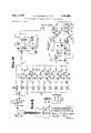
- FIGURE 1 is a block diagram of a controller and modulator system for electronic guitars
- FIGURE 2 is a block diagram of a modification of the system of FIGURE 1;
- FIGURES 3A, 3B taken together are a schematic circuit diagram of a system according to FIGURE 1;
- FIGURE 4 is a schematic circuit diagram of a signal clipper employed in the system of FIGURE 2;
- FIGURE 5 is a tone forming system with button controlled filter capable of replacing a tone forming filter system employed in the system of FIGURES 3A, 3B;
- FIGURES 6A-F indicate schematically the several filters resultant from activation of the several push buttons of FIGURE 5, and their characteristic frequency responses;
- FIGURE 7 illustrates in pictorial and block form one embodiment of the invention
- FIGURE 8 illustrates in pictorial and block form another embodiment of the invention
- FIGURE 9 illustrates in pictorial and block form yet another embodiment of the invention.
- FIGURE 10 illustrates in pictorial and block form a still further embodiment of the invention.
- FIGURE 11 illustrates in block form an embodiment alternative to that of FIGURE 2.
- numeral 10 identifies the pick-up section of an electric guitar and may comprise at least one electromagnetic or piezo-electric transducer per string.
- the output of the pick-up section of the guitar is in electrical form and represents tones, including the partials, generated by the vibrating strings of the instrument. It is known that the relative amplitudes of the partials of any tone can be modified by varying the positions of the string pick-ups with respect to the bridge of the instrument, and the positions of the system of FIGURE 1 are selected to provide a full complement of partials.
- the electrical signals produced by the pick-ups 10 are passed by an isolating amplifier 11 to a series of parallel filters 12, 13, 14, 15, 16, 17, which are tailored to provide desired tone colorations, and which may be selected individually or in combination by the tone-color selection switches 18.
- the tone color filters may include a filter 12 which is purely resistive and therefore passes all partials with the same attenuation, a low-pass filter 13, and a high-pass filter 17, and various tone formant filters 14-16, inclusive. These latter provide tone colorations, at least some of which may be consonant with the outputs f members of the guitar family which differ in kind from the coloration provided by filter 12. For example, if the filter 12 provides the coloration of a rock-and-roll guitar, formant filter 14 may convert the tone to that of an acoustic guitar, etc.
- the output of the filter bank is applied via an amplifier 20 to a modulator 21.
- the latter is provided with sub-audio signal at a frequency suitable for vibrato and/ or tremolo production, by oscillator 22.
- the oscillator 22 is provided with a frequency control, for providing a range of suitable sub-audio oscillations.
- the modulator 21 is capable of providing frequency-modulated output or amplitude-modulated output, in response to modulation signal provided by oscillator 22, at separate output terminals. Modification of frequency deviation is provided by control 23, and depth of amplitude modulation by control 24.
- the frequencyand/ or amplitude-modulated signal is derived in a summing amplifier 25, power amplified in amplifier 26 and radiated by loudspeaker 27.
- FIGURE 2 of the drawings four representative pickups 30, 31, 32 and 33 are illustrated, each of which pertains to a different string of the instrument.
- individual clippers as 34, 35, 36 and 37. These may be individually adjusted to produce desired harmonics or partials on vibration of the strings of the instrument, generally serving to augment the total number of partials available and their amplitudes relative to the amplitude of the fundamenal.
- the several clippers are then connected to tone forming filters 12-17, the outputs of which are utilized precisely as in FIGURE 1, FIGURES 1 and 2 being identical to the right of the line A.
- the specific tone forming filters may or may not be identical in the two forms of the invention, since the precise contours of the filters must be established in terms of the character and extent of the partials which must be filtered to form desired tones.
- FIGURE 3A there is illustrated schematically an isolating amplifier and an array of tone-forming filters such as might be used in the system of FIGURES 1 or 2.
- An input jack 50 is provided which supplies signal from the several string motion transducers to the base 51 of a transistor 52 forming part of a conventional emitter follower amplifier 53.
- the amplifier thus provides isolation between the transducers and following tone coloration filters, while providing suitable impedance matching between the two.
- the output of the amplifier 53 appears on switch 54 and is applied via a bus 55 in common to a series of filters, via selector switches 18.
- the uppermost filter 12 is a resistance pad and accordingly when signal is passed via filter 12, no change occurs in the tone as provided on the bus 55.
- the remaining filters 56, 57, 58, 59, 60, 61, 62 and 63 are all bandpass filters, the several filters 56-63 being of the same configuration but utilizing difierent circuit values.
- the shunt elements of the filters comprise each an inductance, as 6 -1, and a capacitor, as 65, and are tuned to different frequencies.
- the mean frequencies to which the filters are tuned are 175 c.p.s., 330 c.p.s., 460 c.p.s., 600 c.p.s., 770 c.p.s., 980 c.p.s., 1350 c.p.s., and 2000 c.p.s.
- the bandpass filters are in the nature of tone formants and each provides a difierent tone coloration, and some at least may be appropriate to a type of guitar.
- a high-pass filter 66 which passes all frequencies over 2,000 c.p.s., and which is generally of conventional configuration. Outputs of the selected filters applied to a common terminal 70, which in turn is connected to a conventional amplifier, generally indicated by the refernce numeral 72, and the latter supplies the audio signal to a vibrato and tremolo modulator 73, via terminal 75.
- the modulating circuit 73 (FIGURE 3B) is capable of either amplitude modulating to produce tremolo or frequency modulating to produce vibrato, and a subsonic oscillator 74 supplies modulating signal to the modulating circuit 73.
- the amplifier 72 is a conventional two-stage transistorized amplifier, the design constants of which are provided in the accompanying drawings, and which need not be described in detail.
- the output of the amplifier 72 is present at terminal 75, which supplies audio signal in parallel to the bases 76, 77 of two PNP transistors 78 and 79'.
- the collector of transistor 78 is connected to a negative power source 80 (-12 v.) via a small load resistance 78a, and the emitter of the transistor 78 is connected to (+6 v.) through a small resistance 81.
- the terminal 135 is connected to the subsonic oscillator 74, which presents to the terminal 135 a modulated impedance.
- Lead 82 connected to terminal 135, connects this modulated impedance to the emitter of transistor 78.
- the output of transistor 78, at its collector, is thus modulated, i.e. consists of the audio band modulated in amplitude subsonically.
- the amplitude-modulated audio band is coupled from the collector of transistor 78 via capacitor 86 to a terminal 87. From terminal 87 the modulated audio band may proceed, via one of capacitors 100, 101 and lead L to the base of transistor 79. Alternatively, the modulated audio band may proceed via one of resistances 107-110, incl. to a terminal 87a, isolated from terminal 87 by resistance 87b.
- a phase shift is introduced in a path from the collector of transistor 78, to terminal 87, lead L terminal 87a, one of capacitors 100, 101 and to the base 77 of transistor 79.
- variable sub-audio voltage is effectively applied to terminal 135, by varying the load across emitter load 81, the phase shift varies.
- amplitude-modulated audio band present at the collector of transistor 78, can proceed via terminal 87, lead L one of resistances 107-110,
- Diiferent degrees of tremolo i.e., different depths of amplitude modulation, are produced by connecting different attenuating resistances 107, 108, 109, (of values 3.3M, 1.5M, 680 and 330 respectively), between point 87a and a point 111.
- the latter point is connected to ground through a resistance 112, for application to summing amplifier 90.
- the oscillator 74 which supplies modulating signal to the modulating device 73 is an RC oscillator 74 having two cascaded transistors 113, 114, and a phase-shift feedback path 121.
- Phase-shift feedback circuit 121 includes three series capacitors C1, C2, C3 connected in feedback path 121 between the collector of transistor 114 and the base of transistor 113.
- a fixed resistance R1 extends from the junction of C1 and C2 to ground and an adjustable resistance network R2 extends from the junction of C2 and C3 to ground.
- the adjustable resistance R2 includes five parallel paths consisting, except for one path, of a switch and a resistance, the paths being identified by the numerals of reference 124, 126, 128, 130, 132.
- the path 130 includes Zero resistance, so that when it is closed, the oscillator is disabled by shorting of its feedback path 121.
- the remaining parallel paths contain, respectively, different resistances to provide different values of oscillatory frequency for oscillator 74.
- Path 132 contains no switch, so that opening of the 130 path places path 132 in circuit and oscillations occur. As additional paths 124, 126, 128 are closed the oscillatory frequency is modified. But closure of path 130 disables the oscillator regardless of which other paths are open or closed.
- the oscillator rate may be one of several rates, as established by the paths 124, 126, 128, 132, or the oscillator may be turned off by closing the switch 130.
- the modulated impedance seen looking into terminal 135 is produced by diodes D1 and D2, and subaudio current supplied from oscillator 74 via resistance 137.
- the impedance of D1 and D2 is inversely proportional to the forward current through resistor 127. This impedance is then modulated by the subaudio current supplied via resistance 137.
- Capacitors C5 and C6 are selected to be relatively high impedances at the subaudio frequency and relatively low impedances at the audio frequency.
- D1 and D2 are seen in parallel looking into terminal 135. For this condition the diodes are reversed relative to each other and compensate for the non-linearity of each other. This compensation eliminates even-harmonic distortion.
- the tone forming filter system of FIGURE 3A operates brute force, in that it employs multiple independent filters se ectable by switches.
- FIGURE 5 is illustrated a more sophisticated filter in which a limited number of filter components are selectively connected in circuit, at will, to provide desired filter characteristics.
- Six sets of pushbutton-actuated switches are provided, which, when actuated, provide the filter configurations of FIGURES 6a to 6 inclusive.
- FIGURE 5 54 is an input terminal and 70 an output terminal, the numeration corresponding with that employed in FIGURE 3A.
- Signal provided at terminal 54 is applied to a first bus 200.
- a plurality of further buses 200a, 200b, 200a, 200a, is provided, of which 200 represents a first bus, connected to input terminal 54, and 2000! represents a fifth bus, connected to output terminal 70.
- Buses 200a, 200b, 2000 then represent second, third and fourth buses.
- Each of buses 20% and 2000 are shown as double leads, but in fact these double leads are directly interconnected and always carry the same signal.
- the push-button switch actuators available are denoted Sl-S6, inclusive. With S1 actuated, switches S10, S11, S12 are closed, all others being open. A circuit then proceeds through series resistance R10, and via shunt capacitor C10 to ground.
- Resistance R10 proceeds to S10 and thence to coil L10 in parallel with R12, to S11, lead 201, and series resistance R11 and terminal 70, a shunt capacitor C11 being asso ciated with resistance R11. Further, S13 leads to resistance R22, which via S13, and resistance R22, also parallels L10. Further, S12 connects a resistance having 27K in parallel with R11.
- the filter configuration resulting is essentially that of FIGURE 6a.
- switches S20, S22 are closed (and all others opened), providing a circuit from bus 200 to series resistance R and shunt resistance R21, through switch S20 to coil L10, with R12 in parallel with L10, and thence via S22 to R23, C23 to terminal 70.
- the resulting circuit configuration is that of FIGURE 612.
- switches S and S31 are closed, resulting in a circiut through resistance R30, to switch S30, lead 204, which in turn connects to lead 205 and via switch S31 to RC network 205, and terminal 70.
- a coil L2 is connected from lead 205 to ground: the resulting configuration is that of FIGURE 60.
- switches S60 and S61 are closed, providing a circuit composed of C40 and R60 in series, and resistance R61 connected from their junction to ground, i.e., the configuration of FIGURE 6 Rough indications of the pass bands of the several filters are provided adjacent to the filter configurations of FIGURES 6a-6f, plotted to logarithmic scale, with a maximum frequency of 10 kc. and peaks or valleys are numerically provided.
- a low-pass filter (FIGURE 6a) is employed, which provides a soft output in response to guitar music, the filter being generally of the type which would isolate an F0 sound, from a broad frequency spectrum.
- a second filter (FIGURE 6b) is designed to produce an a sound, a third (FIGURE 6c) to produce an a sound, a fourth (FIGURE 6d) to produce a sound between ii and e, a fifth (FIGURE 6e) to produce a sound between a and 6, and a sixth (FIGURE 6 to produce an 5 sound.
- the sounds therefore extend from very soft to strident.
- the filters may also be described as suitable for producing Background, Bass, Mood, Solo, rock and roll and wild dog, types of sound, respectively. Precise circuit values for the circuit components are provided in the accompanying drawings and are not here repeated.
- a filter system such as that illustrated in FIGURE 5 may be physically housed in different locations in an electric guitar system.
- a filter system 150 controlled by actuating means 151, may be placed inside the body of a guitar 152, there being connections as illustrated to a pickup or sensing means 154 and to an output system 156.
- the latter may be a standard guitar amplifier unit having its usual amplifier, controls and loudspeaker (not shown).
- FIGURE 8 Another example of location of a filter system is illustrated in FIGURE 8, wherein the pickup 158 of a guitar 160 is connected as shown to a separate filter box 162, with actuators 163, there being a connection to a stand ard amplifier unit 164.
- FIG- URE 9 A third example of filter location is illustrated in FIG- URE 9, wherein the pickup 166 of a guitar 168 is connected as shown to a filter system 170, with actuators 171, located within an amplifier unit 172.
- FIGURE 10 A fourth example of filter location system is illustrated in FIGURE 10, wherein pickup 174 of a guitar 176 is connected as shown to a filter system 178, with actuators 180, located within the body of the guitar 176, connection being made to an output system 182 located also in the guitar 1.7 6, the circular element 184 representing acoustical radiating means.
- FIGURE 4 represents circuitry of any of clippers 34- 37 of FIGURE 2.
- Signal input is supplied from string vibration transducer coil 300 to the base of transistor 142 and transistor 144 in parallel.
- Transistor 144 supplies signal to a load terminal 301 via a diode 146.
- the transistor 144 is collector loaded, by resistance 302, and the collector supplies negative feedback, via
- FIGURE 11 a pickup section 10a, corresponding to 30-37 inclusive in FIGURE 2, is shown connected to a preamp 11a, which, in turn, is connected to a modulator 21a, the latter two elements corresponding generally to 21, 22-25 of FIGURE 2.
- Subsonic oscillator 22a feeds the modulator 21a.
- Filter section 18a is shown connected between the modulator 21a and output system 26a, the latter corresponding to elements 26 and 27 of FIGURE 2.
- At least one pickup means for sensing the vibrations of each individual string of said guitar
- multiple harmonic generation means connected in cascade with said at least one pickup means
- said harmonic generation means including tone signal clippers which in response to a complex musical tone signal representative of said vibrations generates an array of harmonics harmonically related to the frequencies of said tone signal, and
- tone color filter means coupled between said harmonic generation means and said output system.
- subsonic frequency and amplifier modulation means coupled in series with said filter means to said output means to provide frequency and amplitude vibrato of said tone signals.
- said selective tone color filter component array including a plurality of electrical circuit elements
- said elements including inductances, capacitors and resistances,
- tone color filter array includes plural leads between which is connected at least one filter component
- tone color filter array includes parallel filter paths extending from all said transducers
- plural ones of said switch arrays including each a switch for connecting one of said parallel filter paths to said common lead,
- At least one of said switch arrays including a switch for interconnecting said first and second common leads.
- said selective tone color filter component array including plural simpler tone color filters
- said array includes, connected in series with said source of tone signals and in parallel with each other the inputs of a low pass filter and a resistive p a first bus,
- each path including a separate further switch
- a tone color system for an electronic musical instrument including an input terminal,
Description
Feb. 3, 1970 OUTPUT SYSTEMS FOR ELECTRIC GUITARS AND THE LIKE Filed Dec. 5, 1965 4 Sheets-Sheet 1 l all- 23 I I Mm L.P. P fioneerase OP PEEQMOD I P\CK-UP 2O iff SECTION K5 T 5 MOD W sum Aw \TA Q GU R M 2& L25
-{FoRMAuT|- sua- MD A SONIC 1g 57 (FQEQ 3] r l I PlCK-UP cuppez TONE ST 32 3 I vgm gg MOD SUM AMP I PICK-UP cuPPEQ I 20 26 53 37 g 75 25 27 -n PlCK-UP CLIPPER 1 23 --AMP MOD A osc.
5Q ISI r 1 OUTPUT L L" D Pu SYSTEM x54 [56 BY INVENTORS THOMAS wfiuumuenm kDONALD UELBRECHT y ow-z ATTORNEYS Feb. 3, 1970 w. ELBRECHT ET L 3,493,569
OUTPUT SYSTEMS FOR ELECTRIC GUITARS AND THE LIKE Filed Dec. 5, 1965 4 Sheets-Sheet 2 -91: Hamw (NORM. cwssn) a? ON AMPLIFI R INVENTORS THOMH$ wcuumnsHAM FrDoumo uLELBREcHT WM Au .1
ATTORNEYS- Feb. 3, 1970 w. ELBRECHT ET L OUTPUT SYSTEMS FOR ELECTRIC GUITARS AND THE LIKE 4 Sheets-Sheet .3
Filed Dec. s.- 1965 l M T 2 8H WW M :2 05 W. W f m MOEJBQZ W M T m W m 0+ M M w w 7 M N W sm 00 V m. e M Q. mm 2. M# h 1 1 mm h .g TH I oo z o: u g 0 or n M omflom, 9 am an 8% E m 263 mm IFSAEIDO N m Q Emil uwo 0 m2 HJIL 0mm 4 Omfi 000 Q0 m; .H 1mm Pod NNOO. v.00 2Q 81 81 m 0E v m: N o q w: mow wow QZJmwE 3 W w w w ..u.. w 4 @556 2m ATTORNEYS I 1.970 D. w. ELBRECHT ET AL OUTPUT SYSTEMS FOR ELECTRIC GUITARS AND THE LIKE Filed Deb. 5. 1965 4 Sheets-Sheet 4 mo {ED 2. 723.
vOON INVENTORS THOMAS blCuumueHAM GYDONQLD l1 ELBREcHT M )1. I ATTORNEYS United States Patent 3,493,669 OUTPUT SYSTEMS FOR ELECTRIC GUITARS AND THE LIKE Donald W. Elbrecht, Milford, and Thomas W. Cunningham, Cincinnati, Ohio, assignors to D. H. Baldwin Company, Cincinnati, Ohio, a corporation of Ohio Filed Dec. 3, 1965, Ser. No. 511,514 Int. Cl. Gh 3/00 US. Cl. 841.16 10 Claims ABSTRACT OF THE DISCLOSURE The present invention relates generally to electronic musical instruments, and more particularly to electronic stringed instruments, wherein transducers coupled to the strings are used as tone sources, and wherein the tonal outputs of the strings may be modified in a variety of ways in pre-established degrees by means of a limited number of simple on-oif controls, and in such manner as to simulate at will the tonal output of some members at least of an entire family of stringed instruments.
Many instruments of a family, e.g., the guitar family, are made in various forms, sizes, and tone capabilities. In such case, the musician may be impelled to own and to transport and have available for playing and example of each form of the instrument contained within the family, at considerable cost and inconvenience. Electric Electric guitars are known which transduce the motion of the strings of a guitar to electrical signals, and filter the signals to modify the timbre or quality of the tone prior to electro-acoustical transduction and radiation of the signals. According to the present invention the filters employed to modify tone quality are specifically designed to produce tone qualities appropriate to the several individuals of a family of instruments. For example, in the case of the guitar, there are the classic guitar, the type used for Western music, the rock-and-roll guitar, the Hawaiian guitar, the bass guitar, the solo guitar, and the like.
The modification of timbre or tone quality alone does not exhaust the possibilities of modifying guitar tones electrically. In accordance with a further feature of the invention, a modulator is provided which can provide pre-selected frequencies of either vibrato or tremolo, and at various modulation depths for tremolo and frequency deviations for vibrato. The various selections to be made are available by push-button activated switches, so that reproducibility of tone is always available, in terms of manipulation of selected switches. The switch actuators can be interlocked so that selection of one tone quality, for example, disables selection of all others.
It is, accordingly, a broad object of the invention to provide easily reproducible electrical simulations of, and enhancements of the tones of some at least of a family of guitars, while only one member of the family is being played.
For some forms of pickups used in stringed instruments, and for some locations of the pickups with respect to the bridge of an instrument, many of the partials of the tones of the instrument are not transduced. Partials may be added, according to the invention, by clipping the tones as actually tranduced, and the tone forming filters may then be designed to select desired relative partial amplitudes of the complex wave provided by the clippers in order to generate desired tone colorations.
Another feature of the invention resides in the pro vision of a modulator capable of modulating, in both frequency and amplitude, a wide-band spectrum representing musical tones, the frequency-modulated and amplitudemodulated tones being available at separate output ter- 3,493,669 Patented Feb. 3, 1970 ICC minals, and the extent of frequency deviation and the depth of amplitude modulation being selectable at will.
It is another object of the invention to solve the problem of providing a large number of tone qualities at low cost by providing for multiple usage of circuit components in different filters.
The above and still further objects, features and advantages of the present invention will be come apparent upon consideration of the following detailed description of, one specific embodiment thereof, especially when taken in conjunction with the accompanying drawings, wherein:
FIGURE 1 is a block diagram of a controller and modulator system for electronic guitars;
FIGURE 2 is a block diagram of a modification of the system of FIGURE 1;
FIGURES 3A, 3B taken together are a schematic circuit diagram of a system according to FIGURE 1;
FIGURE 4 is a schematic circuit diagram of a signal clipper employed in the system of FIGURE 2;
FIGURE 5 is a tone forming system with button controlled filter capable of replacing a tone forming filter system employed in the system of FIGURES 3A, 3B;
FIGURES 6A-F indicate schematically the several filters resultant from activation of the several push buttons of FIGURE 5, and their characteristic frequency responses;
FIGURE 7 illustrates in pictorial and block form one embodiment of the invention;
FIGURE 8 illustrates in pictorial and block form another embodiment of the invention;
FIGURE 9 illustrates in pictorial and block form yet another embodiment of the invention;
FIGURE 10 illustrates in pictorial and block form a still further embodiment of the invention; and
FIGURE 11 illustrates in block form an embodiment alternative to that of FIGURE 2.
Referring now to the accompanying drawings, in FIGURE 1, numeral 10 identifies the pick-up section of an electric guitar and may comprise at least one electromagnetic or piezo-electric transducer per string. The output of the pick-up section of the guitar is in electrical form and represents tones, including the partials, generated by the vibrating strings of the instrument. It is known that the relative amplitudes of the partials of any tone can be modified by varying the positions of the string pick-ups with respect to the bridge of the instrument, and the positions of the system of FIGURE 1 are selected to provide a full complement of partials.
The electrical signals produced by the pick-ups 10 are passed by an isolating amplifier 11 to a series of parallel filters 12, 13, 14, 15, 16, 17, which are tailored to provide desired tone colorations, and which may be selected individually or in combination by the tone-color selection switches 18. The tone color filters may include a filter 12 which is purely resistive and therefore passes all partials with the same attenuation, a low-pass filter 13, and a high-pass filter 17, and various tone formant filters 14-16, inclusive. These latter provide tone colorations, at least some of which may be consonant with the outputs f members of the guitar family which differ in kind from the coloration provided by filter 12. For example, if the filter 12 provides the coloration of a rock-and-roll guitar, formant filter 14 may convert the tone to that of an acoustic guitar, etc.
The output of the filter bank is applied via an amplifier 20 to a modulator 21. The latter is provided with sub-audio signal at a frequency suitable for vibrato and/ or tremolo production, by oscillator 22. The oscillator 22 is provided with a frequency control, for providing a range of suitable sub-audio oscillations. The modulator 21 is capable of providing frequency-modulated output or amplitude-modulated output, in response to modulation signal provided by oscillator 22, at separate output terminals. Modification of frequency deviation is provided by control 23, and depth of amplitude modulation by control 24. The frequencyand/ or amplitude-modulated signal is derived in a summing amplifier 25, power amplified in amplifier 26 and radiated by loudspeaker 27.
It is a feature of the invention to provide selective tones, frequencies of modulation, deviations of frequency modulation and depth of amplitude modulation, by pushbutton control. This assures reproducibility and ease of control. To accomplish this result, the various controls are incorporated in push-button form, so that operation of selected push buttons generates pre-selected tone colorations which are always the same for a given selection of push buttons.
It is well known in the art of electrical guitars that the location of the pick-ups of mechanical-electrical transducers with respect to the bridge of the instrument determines the cnaracter of the overtones which will be transduced. It can, therefore, be the case that many overtones present in the audible music produced by the strings themselves are not transduced, depending on pickup location, or it can be the case that even though all partials are transduced, many of these are in lesser amplitude at the transducers than they are in the actual instrument. To overcome this difficulty, use can be made of individual clippers, one in series with each pick-up.
Referring now to FIGURE 2 of the drawings, four representative pickups 30, 31, 32 and 33 are illustrated, each of which pertains to a different string of the instrument. In cascade with the separate pick-ups are individual clippers as 34, 35, 36 and 37. These may be individually adjusted to produce desired harmonics or partials on vibration of the strings of the instrument, generally serving to augment the total number of partials available and their amplitudes relative to the amplitude of the fundamenal. The several clippers are then connected to tone forming filters 12-17, the outputs of which are utilized precisely as in FIGURE 1, FIGURES 1 and 2 being identical to the right of the line A. However, the specific tone forming filters may or may not be identical in the two forms of the invention, since the precise contours of the filters must be established in terms of the character and extent of the partials which must be filtered to form desired tones.
In FIGURE 3A there is illustrated schematically an isolating amplifier and an array of tone-forming filters such as might be used in the system of FIGURES 1 or 2. An input jack 50 is provided which supplies signal from the several string motion transducers to the base 51 of a transistor 52 forming part of a conventional emitter follower amplifier 53. The amplifier thus provides isolation between the transducers and following tone coloration filters, while providing suitable impedance matching between the two. The output of the amplifier 53 appears on switch 54 and is applied via a bus 55 in common to a series of filters, via selector switches 18. The uppermost filter 12 is a resistance pad and accordingly when signal is passed via filter 12, no change occurs in the tone as provided on the bus 55. The remaining filters 56, 57, 58, 59, 60, 61, 62 and 63 are all bandpass filters, the several filters 56-63 being of the same configuration but utilizing difierent circuit values. The shunt elements of the filters comprise each an inductance, as 6 -1, and a capacitor, as 65, and are tuned to different frequencies. In the order of the numerals of reference, i.e., 56 to 63, incl., the mean frequencies to which the filters are tuned are 175 c.p.s., 330 c.p.s., 460 c.p.s., 600 c.p.s., 770 c.p.s., 980 c.p.s., 1350 c.p.s., and 2000 c.p.s. The bandpass filters are in the nature of tone formants and each provides a difierent tone coloration, and some at least may be appropriate to a type of guitar. In addition to the filters already described, a high-pass filter 66 is provided which passes all frequencies over 2,000 c.p.s., and which is generally of conventional configuration. Outputs of the selected filters applied to a common terminal 70, which in turn is connected to a conventional amplifier, generally indicated by the refernce numeral 72, and the latter supplies the audio signal to a vibrato and tremolo modulator 73, via terminal 75.
The modulating circuit 73 (FIGURE 3B) is capable of either amplitude modulating to produce tremolo or frequency modulating to produce vibrato, and a subsonic oscillator 74 supplies modulating signal to the modulating circuit 73.
The amplifier 72 is a conventional two-stage transistorized amplifier, the design constants of which are provided in the accompanying drawings, and which need not be described in detail. The output of the amplifier 72 is present at terminal 75, which supplies audio signal in parallel to the bases 76, 77 of two PNP transistors 78 and 79'. The collector of transistor 78 is connected to a negative power source 80 (-12 v.) via a small load resistance 78a, and the emitter of the transistor 78 is connected to (+6 v.) through a small resistance 81.
The terminal 135 is connected to the subsonic oscillator 74, which presents to the terminal 135 a modulated impedance. Lead 82, connected to terminal 135, connects this modulated impedance to the emitter of transistor 78. The output of transistor 78, at its collector, is thus modulated, i.e. consists of the audio band modulated in amplitude subsonically.
The amplitude-modulated audio band is coupled from the collector of transistor 78 via capacitor 86 to a terminal 87. From terminal 87 the modulated audio band may proceed, via one of capacitors 100, 101 and lead L to the base of transistor 79. Alternatively, the modulated audio band may proceed via one of resistances 107-110, incl. to a terminal 87a, isolated from terminal 87 by resistance 87b.
Considering the frequency vibrato modulated aspect of modulator 73, a phase shift is introduced in a path from the collector of transistor 78, to terminal 87, lead L terminal 87a, one of capacitors 100, 101 and to the base 77 of transistor 79. As variable sub-audio voltage is effectively applied to terminal 135, by varying the load across emitter load 81, the phase shift varies.
On the other hand, amplitude-modulated audio band, present at the collector of transistor 78, can proceed via terminal 87, lead L one of resistances 107-110,
incl., lead L to terminal 87a. Depth of amplitude modulation is selected by selection of resistances 107 to 110, incl. Accordingly vibrato output derives from the terminal 93, while tremolo output is selectively switched via switches 114, 116, 118 and 120 from terminal 87, and appears on terminal 87a. So long as switches 102, 103 are open there is no vibrato, since the base of transistor 79 is disconnected from the coupling capacitor 86. When one of the vibrato switches 102, 103 is closed, the output of the transistor 78 feds through one of capacitors 100, 101, to provide selective vibrato swings or deviations of frequency.
When both frequency vibrato switches 102, 103 are open, and one of switches 114, 116, 118, 120 closed, amplitude vibrato, or tremolo, is produced.
Diiferent degrees of tremolo i.e., different depths of amplitude modulation, are produced by connecting different attenuating resistances 107, 108, 109, (of values 3.3M, 1.5M, 680 and 330 respectively), between point 87a and a point 111. The latter point is connected to ground through a resistance 112, for application to summing amplifier 90.
The oscillator 74 which supplies modulating signal to the modulating device 73 is an RC oscillator 74 having two cascaded transistors 113, 114, and a phase-shift feedback path 121. Phase-shift feedback circuit 121 includes three series capacitors C1, C2, C3 connected in feedback path 121 between the collector of transistor 114 and the base of transistor 113. A fixed resistance R1 extends from the junction of C1 and C2 to ground and an adjustable resistance network R2 extends from the junction of C2 and C3 to ground. The adjustable resistance R2 includes five parallel paths consisting, except for one path, of a switch and a resistance, the paths being identified by the numerals of reference 124, 126, 128, 130, 132. The path 130 includes Zero resistance, so that when it is closed, the oscillator is disabled by shorting of its feedback path 121. The remaining parallel paths contain, respectively, different resistances to provide different values of oscillatory frequency for oscillator 74. Path 132 contains no switch, so that opening of the 130 path places path 132 in circuit and oscillations occur. As additional paths 124, 126, 128 are closed the oscillatory frequency is modified. But closure of path 130 disables the oscillator regardless of which other paths are open or closed.
Accordingly, the oscillator rate may be one of several rates, as established by the paths 124, 126, 128, 132, or the oscillator may be turned off by closing the switch 130. The modulated impedance seen looking into terminal 135 is produced by diodes D1 and D2, and subaudio current supplied from oscillator 74 via resistance 137. The impedance of D1 and D2 is inversely proportional to the forward current through resistor 127. This impedance is then modulated by the subaudio current supplied via resistance 137. Capacitors C5 and C6 are selected to be relatively high impedances at the subaudio frequency and relatively low impedances at the audio frequency. At the audio frequency D1 and D2 are seen in parallel looking into terminal 135. For this condition the diodes are reversed relative to each other and compensate for the non-linearity of each other. This compensation eliminates even-harmonic distortion.
The tone forming filter system of FIGURE 3A operates brute force, in that it employs multiple independent filters se ectable by switches. In FIGURE 5 is illustrated a more sophisticated filter in which a limited number of filter components are selectively connected in circuit, at will, to provide desired filter characteristics. Six sets of pushbutton-actuated switches are provided, which, when actuated, provide the filter configurations of FIGURES 6a to 6 inclusive.
In FIGURE 5, 54 is an input terminal and 70 an output terminal, the numeration corresponding with that employed in FIGURE 3A.
Signal provided at terminal 54 is applied to a first bus 200. A plurality of further buses 200a, 200b, 200a, 200a, is provided, of which 200 represents a first bus, connected to input terminal 54, and 2000! represents a fifth bus, connected to output terminal 70. Buses 200a, 200b, 2000, then represent second, third and fourth buses. Each of buses 20% and 2000 are shown as double leads, but in fact these double leads are directly interconnected and always carry the same signal. The push-button switch actuators available are denoted Sl-S6, inclusive. With S1 actuated, switches S10, S11, S12 are closed, all others being open. A circuit then proceeds through series resistance R10, and via shunt capacitor C10 to ground. Resistance R10 proceeds to S10 and thence to coil L10 in parallel with R12, to S11, lead 201, and series resistance R11 and terminal 70, a shunt capacitor C11 being asso ciated with resistance R11. Further, S13 leads to resistance R22, which via S13, and resistance R22, also parallels L10. Further, S12 connects a resistance having 27K in parallel with R11. The filter configuration resulting is essentially that of FIGURE 6a.
If push-button S2 is actuated, switches S20, S22 are closed (and all others opened), providing a circuit from bus 200 to series resistance R and shunt resistance R21, through switch S20 to coil L10, with R12 in parallel with L10, and thence via S22 to R23, C23 to terminal 70. The resulting circuit configuration is that of FIGURE 612.
With switch S3 push-button actuated, switches S and S31 are closed, resulting in a circiut through resistance R30, to switch S30, lead 204, which in turn connects to lead 205 and via switch S31 to RC network 205, and terminal 70. A coil L2 is connected from lead 205 to ground: the resulting configuration is that of FIGURE 60.
When push button S4 is actuated, switches S40, S41, S42 and S43 are closed. A circuit then proceeds from bus 200, R10, C10, S40, L10, R12, S41, lead 201 and R11, C11. In addition, a circiut proceeds from bus 200, to capacitor C40. S42, S43, and resistances R40, R41 to terminal 70, whereby coil L2 is connected to ground at the junction of C40 and R40 plus R41. The circuit configuration is thus that of FIGURE 6d.
When S5 push button is actuated, switches S50 and S51 are closed. The resulting circuit includes C40 and R41 in series, with L2 connected from their junction to ground, i.e. the configuration of FIGURE 6e.
When S6 push button is actuated, switches S60 and S61 are closed, providing a circuit composed of C40 and R60 in series, and resistance R61 connected from their junction to ground, i.e., the configuration of FIGURE 6 Rough indications of the pass bands of the several filters are provided adjacent to the filter configurations of FIGURES 6a-6f, plotted to logarithmic scale, with a maximum frequency of 10 kc. and peaks or valleys are numerically provided.
We have arrived at the conclusion, after much experimentation, that the use of vowel formants as a basis for designing guitar tone forming filters, presents a useful approach. For example, a low-pass filter (FIGURE 6a) is employed, which provides a soft output in response to guitar music, the filter being generally of the type which would isolate an F0 sound, from a broad frequency spectrum. A second filter (FIGURE 6b) is designed to produce an a sound, a third (FIGURE 6c) to produce an a sound, a fourth (FIGURE 6d) to produce a sound between ii and e, a fifth (FIGURE 6e) to produce a sound between a and 6, and a sixth (FIGURE 6 to produce an 5 sound. The sounds therefore extend from very soft to strident. The filters may also be described as suitable for producing Background, Bass, Mood, Solo, rock and roll and wild dog, types of sound, respectively. Precise circuit values for the circuit components are provided in the accompanying drawings and are not here repeated.
A filter system such as that illustrated in FIGURE 5 may be physically housed in different locations in an electric guitar system. For example, in FIGURE 7, a filter system 150, controlled by actuating means 151, may be placed inside the body of a guitar 152, there being connections as illustrated to a pickup or sensing means 154 and to an output system 156. The latter may be a standard guitar amplifier unit having its usual amplifier, controls and loudspeaker (not shown).
Another example of location of a filter system is illustrated in FIGURE 8, wherein the pickup 158 of a guitar 160 is connected as shown to a separate filter box 162, with actuators 163, there being a connection to a stand ard amplifier unit 164.
A third example of filter location is illustrated in FIG- URE 9, wherein the pickup 166 of a guitar 168 is connected as shown to a filter system 170, with actuators 171, located within an amplifier unit 172.
A fourth example of filter location system is illustrated in FIGURE 10, wherein pickup 174 of a guitar 176 is connected as shown to a filter system 178, with actuators 180, located within the body of the guitar 176, connection being made to an output system 182 located also in the guitar 1.7 6, the circular element 184 representing acoustical radiating means.
FIGURE 4 represents circuitry of any of clippers 34- 37 of FIGURE 2. Signal input is supplied from string vibration transducer coil 300 to the base of transistor 142 and transistor 144 in parallel. Transistor 144 supplies signal to a load terminal 301 via a diode 146.
The transistor 144 is collector loaded, by resistance 302, and the collector supplies negative feedback, via
In the system of FIGURE 2, there was shown an embodiment in which the filters were ahead of the modulator. One skilled in the art will realize that the locations of these elements may be reversed. In FIGURE 11, a pickup section 10a, corresponding to 30-37 inclusive in FIGURE 2, is shown connected to a preamp 11a, which, in turn, is connected to a modulator 21a, the latter two elements corresponding generally to 21, 22-25 of FIGURE 2. Subsonic oscillator 22a feeds the modulator 21a. Filter section 18a is shown connected between the modulator 21a and output system 26a, the latter corresponding to elements 26 and 27 of FIGURE 2.
While we have described and illustrated one specific embodiment of our invention, it will be clear that variations of the details of construction which are specifically illustrated and described may be resorted to without departing from the true spirit and scope of the invention as defined in the appended claims.
We claim:
1. In an electric guitar system and the like, the combination comprising:
at least one pickup means for sensing the vibrations of each individual string of said guitar,
multiple harmonic generation means connected in cascade with said at least one pickup means,
vibrato modulation means connected in cascade with said harmonic generation means,
an electro acoustic output system connected in cascade with said modulation means,
said harmonic generation means including tone signal clippers which in response to a complex musical tone signal representative of said vibrations generates an array of harmonics harmonically related to the frequencies of said tone signal, and
tone color filter means coupled between said harmonic generation means and said output system.
2. The combination according to claim 1, wherein said filter means comprise:
a plurality of parallel-arranged, band-pass filters having different pass regions, and
switching means associated with each of said filters,
whereby different bands may be selected at will.
3. The combination according to claim 1, including:
subsonic frequency and amplifier modulation means coupled in series with said filter means to said output means to provide frequency and amplitude vibrato of said tone signals.
4. In an electric guitar system,
a source of tone signals,
a load,
a selective tone color filter component array connected in cascade between said source and said load,
said selective tone color filter component array including a plurality of electrical circuit elements,
said elements including inductances, capacitors and resistances,
a plurality of multiple switch assemblies each comprising a plurality of switches,
a plurality of separate actuators each operative to operate all the switches of one of said multiple switch assemblies, and
means connecting said circuit elements with said switches in such interconnection that the same circuit elements are common to and are interconnected by plural ones of said switches to synthesize a tone color filter and that operation of each different one of said actuators synthesizes a different tone color filter containing selected ones of said circuit elements which are common to plural ones of said filters.
5. The combination according to claim 4, wherein said tone color filter array includes plural leads between which is connected at least one filter component, and
means connecting in common contacts of diverse ones of said switches to said common leads. 6. The combination according to claim 4, wherein said tone color filter array includes parallel filter paths extending from all said transducers,
a first common lead,
plural ones of said switch arrays including each a switch for connecting one of said parallel filter paths to said common lead,
a second common lead,
a filter component permanently connected between said first and second common leads,
at least one of said switch arrays including a switch for interconnecting said first and second common leads.
7. In an electric music system,
a source of tone signals,
a load,
a selective tone color filter component array connected in cascade between said source and said load,
said selective tone color filter component array including plural simpler tone color filters,
a plurality of multiple switch assemblies each including a plurality of normally open switches,
a plurality of separate actuators each arranged to close the switches of one only of said assemblies,
means responsive to actuation of each of said actuators for interconnecting selected ones of said simpler tone color filters into more complex tone color filters connected between said transducers and said load,
wherein at least some of said simpler tone color filters are common to plural ones of said actuators,
wherein said array includes, connected in series with said source of tone signals and in parallel with each other the inputs of a low pass filter and a resistive p a first bus,
switches for selectively connecting the outputs of said low pass filter and said resistive pad to said first bus,
a second bus,
a parallel inductance-resistance filter permanently connected between said first bus and said second bus,
parallel paths extending from said second bus,
each path including a separate further switch,
a third bus,
further switches for selectively connecting said second bus to said third bus and said first bus to said third bus,
a fourth bus,
a plurality of further diverse low pass filters,
still further switches for selectively connecting the inputs of said further diverse low pass filters to said fourth bus, and
means connecting the outputs of said further low pass filters to said load.
8. A tone color system for an electronic musical instrument, including an input terminal,
an output terminal,
first, second, third, fourth and fifth buses,
means connecting said input terminal to said first bus and said output terminal to said fifth bus,
a plurality of diverse first filters,
means connecting said first filters selectively at will between said first and second buses,
a second filter comprising inductance,
means connecting said second filter between said second and third buses,
means connecting said second and third buses selectively at will to said fourth bus and to said fifth bus,
a plurality of diverse second filters, and
means connecting said diverse second filters selectively at will between said fourth and said fifth buses.
9. The combination according to claim 8, wherein is further provided a filter inductance connected between said fourth bus and ground.
References Cited UNITED STATES PATENTS Dudley.
Nagata et al.
Bennett et al.
Krauss 84--1.25 X
10 3,213,180 10/1965 Cookerly et a1 841.16 3,215,767 11/1965 Martin. 3,307,050 2/1967 Castle 841.19 X 3,340,343 9/1967 W011 841.16 X
5 HERMAN KARL SAALBACH, Primary Examiner P. L. G'ENSLER, Assistant Examiner US. Cl. X.R.
Applications Claiming Priority (1)
| Application Number | Priority Date | Filing Date | Title |
|---|---|---|---|
| US51151465A | 1965-12-03 | 1965-12-03 |
Publications (1)
| Publication Number | Publication Date |
|---|---|
| US3493669A true US3493669A (en) | 1970-02-03 |
Family
ID=24035222
Family Applications (1)
| Application Number | Title | Priority Date | Filing Date |
|---|---|---|---|
| US511514A Expired - Lifetime US3493669A (en) | 1965-12-03 | 1965-12-03 | Output systems for electric guitars and the like |
Country Status (1)
| Country | Link |
|---|---|
| US (1) | US3493669A (en) |
Cited By (39)
| Publication number | Priority date | Publication date | Assignee | Title |
|---|---|---|---|---|
| US3553338A (en) * | 1969-02-19 | 1971-01-05 | Kaman Corp | Music amplifier with tone modifying stage |
| US3591699A (en) * | 1968-03-28 | 1971-07-06 | Royce L Cutler | Music voicing circuit deriving an input from a conventional musical instrument and providing voiced musical tones utilizing the fundamental tones from the conventional musical instrument |
| US3603714A (en) * | 1968-10-04 | 1971-09-07 | Nippon Musical Instruments Mfg | Method and system for generating tremolo effects in electronic musical instruments |
| US3619468A (en) * | 1970-03-05 | 1971-11-09 | Columbia Broadcasting Systems | Stringed musical instrument with piezoelectric transducer providing gate control and music signals |
| US3647928A (en) * | 1970-03-16 | 1972-03-07 | William D Turner | Electrical musical instrument with ensemble and chief effects and unequal stereophonic outputs |
| US3651242A (en) * | 1970-06-15 | 1972-03-21 | Columbia Broadcasting Syst Inc | Octave jumper for musical instruments |
| US3662641A (en) * | 1970-10-01 | 1972-05-16 | Joseph Stevens Allen | Electronic musical apparatus |
| US3742113A (en) * | 1971-04-28 | 1973-06-26 | M Cohen | Stringed musical instrument with electrical feedback |
| US3742114A (en) * | 1971-07-22 | 1973-06-26 | R Barkan | Guitar-like electronic musical instrument using resistor strips and potentiometer means to activate tone generators |
| US3746774A (en) * | 1970-12-25 | 1973-07-17 | Nippon Musical Instruments Mfg | Mandoline effect producing circuit for electronic musical instrument |
| US3767833A (en) * | 1971-10-05 | 1973-10-23 | Computone Inc | Electronic musical instrument |
| US3911776A (en) * | 1973-11-01 | 1975-10-14 | Musitronics Corp | Sound effects generator |
| US3915048A (en) * | 1974-08-05 | 1975-10-28 | Norlin Music Inc | Electric guitar circuit |
| US3943465A (en) * | 1969-10-15 | 1976-03-09 | Nippon Gakki Seizo Kabushiki Kaisha | Frequency-deviation method and apparatus |
| DE2526457A1 (en) * | 1974-08-28 | 1976-03-11 | Warwick Electronics Inc | ELECTRONIC SYNTHESIZER WITH A VARIABLE PRESELECTION VOICE CONTROL |
| US3948138A (en) * | 1973-03-30 | 1976-04-06 | Gunn Gary J | Vibrating string-modulated electronic musical instrument |
| US3973223A (en) * | 1969-10-15 | 1976-08-03 | Nippon Gakki Seizo Kabushiki Kaisha | Frequency-deviation method and apparatus |
| US3973462A (en) * | 1969-10-15 | 1976-08-10 | Nippon Gakki Seizo Kabushiki Kaisha | Frequency-deviation method and apparatus |
| US4030397A (en) * | 1972-06-12 | 1977-06-21 | Nelson Walter E | Electrically amplified musical instrument control apparatus |
| US4064778A (en) * | 1969-10-15 | 1977-12-27 | Nippon Gakki Seizo Kabushiki Kaisha | Frequency-deviation method and apparatus |
| US4117413A (en) * | 1977-06-21 | 1978-09-26 | Norlin Music, Inc. | Amplifier with multifilter |
| US4151368A (en) * | 1975-08-07 | 1979-04-24 | CMB Colonia Management- und Beratungsgesellschaft mbH & Co. KG. | Music synthesizer with breath-sensing modulator |
| US4545278A (en) * | 1983-04-06 | 1985-10-08 | Fender Musical Instruments Corporation | Apparatus and method for adjusting the characteristic sounds of electric guitars, and for controlling tones |
| US4701957A (en) * | 1986-11-26 | 1987-10-20 | Smith Randall C | Dual mode music instrument preamplifier |
| US4819537A (en) * | 1984-08-10 | 1989-04-11 | Hayes Joseph F | Helmholtz resonant simulator |
| US4916409A (en) * | 1988-06-15 | 1990-04-10 | Tracy Daniel L | Signal conditioner system for musical instruments |
| US5124668A (en) * | 1988-11-18 | 1992-06-23 | Cb Labs | System for creating distortion in electric musical instruments |
| US5550508A (en) * | 1995-01-09 | 1996-08-27 | Trentino; Salvatore J. | Phase inverter selection apparatus for tone alteration in a tube-type audio amplifier |
| US5814752A (en) * | 1997-01-15 | 1998-09-29 | Rivera; Paul E. | Musical instrument crossover circuits and method of using same |
| WO1998047132A1 (en) * | 1997-04-16 | 1998-10-22 | Fender Musical Instruments Corporation | Compensation circuit for piezoelectric pickup |
| EP1145219A1 (en) * | 1999-01-15 | 2001-10-17 | Fishman Transducers, Inc. | Measurement and processing of stringed acoustic instrument signals |
| US6610917B2 (en) * | 1998-05-15 | 2003-08-26 | Lester F. Ludwig | Activity indication, external source, and processing loop provisions for driven vibrating-element environments |
| US7309829B1 (en) | 1998-05-15 | 2007-12-18 | Ludwig Lester F | Layered signal processing for individual and group output of multi-channel electronic musical instruments |
| WO2009021218A1 (en) * | 2007-08-08 | 2009-02-12 | Obbligato, Inc. | Intuitive electric guitar switching for selecting sounds of popular guitars |
| US20110210943A1 (en) * | 2010-03-01 | 2011-09-01 | Lester F. Ludwig | Curve-fitting approach to hdtp parameter extraction |
| US8477111B2 (en) | 2008-07-12 | 2013-07-02 | Lester F. Ludwig | Advanced touch control of interactive immersive imaging applications via finger angle using a high dimensional touchpad (HDTP) touch user interface |
| US8509542B2 (en) | 2009-03-14 | 2013-08-13 | Lester F. Ludwig | High-performance closed-form single-scan calculation of oblong-shape rotation angles from binary images of arbitrary size and location using running sums |
| US8766082B2 (en) | 2010-12-21 | 2014-07-01 | Mesa/Boogie, Ltd. | Amplifier with selectable master control |
| US9950256B2 (en) | 2010-08-05 | 2018-04-24 | Nri R&D Patent Licensing, Llc | High-dimensional touchpad game controller with multiple usage and networking modalities |
Citations (8)
| Publication number | Priority date | Publication date | Assignee | Title |
|---|---|---|---|---|
| US2194298A (en) * | 1937-12-23 | 1940-03-19 | Bell Telephone Labor Inc | System for the artificial production of vocal or other sounds |
| US2575993A (en) * | 1948-11-27 | 1951-11-20 | Bell Telephone Labor Inc | Multiple carrier transmission system |
| US3048792A (en) * | 1958-07-08 | 1962-08-07 | Conn Ltd C G | Tone generator with selective switching means |
| US3087989A (en) * | 1959-02-24 | 1963-04-30 | Nippon Electric Co | Vowel synthesizer |
| US3213180A (en) * | 1961-11-20 | 1965-10-19 | Jack C Cookerly | Tone generation system |
| US3215767A (en) * | 1962-01-23 | 1965-11-02 | Baldwin Co D H | Chorus effects in electronic organ |
| US3307050A (en) * | 1967-02-28 | Memory switching circuit | ||
| US3340343A (en) * | 1964-05-06 | 1967-09-05 | Baldwin Co D H | Stringless guitar-like electronic musical instrument |
-
1965
- 1965-12-03 US US511514A patent/US3493669A/en not_active Expired - Lifetime
Patent Citations (8)
| Publication number | Priority date | Publication date | Assignee | Title |
|---|---|---|---|---|
| US3307050A (en) * | 1967-02-28 | Memory switching circuit | ||
| US2194298A (en) * | 1937-12-23 | 1940-03-19 | Bell Telephone Labor Inc | System for the artificial production of vocal or other sounds |
| US2575993A (en) * | 1948-11-27 | 1951-11-20 | Bell Telephone Labor Inc | Multiple carrier transmission system |
| US3048792A (en) * | 1958-07-08 | 1962-08-07 | Conn Ltd C G | Tone generator with selective switching means |
| US3087989A (en) * | 1959-02-24 | 1963-04-30 | Nippon Electric Co | Vowel synthesizer |
| US3213180A (en) * | 1961-11-20 | 1965-10-19 | Jack C Cookerly | Tone generation system |
| US3215767A (en) * | 1962-01-23 | 1965-11-02 | Baldwin Co D H | Chorus effects in electronic organ |
| US3340343A (en) * | 1964-05-06 | 1967-09-05 | Baldwin Co D H | Stringless guitar-like electronic musical instrument |
Cited By (79)
| Publication number | Priority date | Publication date | Assignee | Title |
|---|---|---|---|---|
| US3591699A (en) * | 1968-03-28 | 1971-07-06 | Royce L Cutler | Music voicing circuit deriving an input from a conventional musical instrument and providing voiced musical tones utilizing the fundamental tones from the conventional musical instrument |
| US3603714A (en) * | 1968-10-04 | 1971-09-07 | Nippon Musical Instruments Mfg | Method and system for generating tremolo effects in electronic musical instruments |
| US3553338A (en) * | 1969-02-19 | 1971-01-05 | Kaman Corp | Music amplifier with tone modifying stage |
| US3973223A (en) * | 1969-10-15 | 1976-08-03 | Nippon Gakki Seizo Kabushiki Kaisha | Frequency-deviation method and apparatus |
| US3943465A (en) * | 1969-10-15 | 1976-03-09 | Nippon Gakki Seizo Kabushiki Kaisha | Frequency-deviation method and apparatus |
| US3973462A (en) * | 1969-10-15 | 1976-08-10 | Nippon Gakki Seizo Kabushiki Kaisha | Frequency-deviation method and apparatus |
| US4064778A (en) * | 1969-10-15 | 1977-12-27 | Nippon Gakki Seizo Kabushiki Kaisha | Frequency-deviation method and apparatus |
| US3619468A (en) * | 1970-03-05 | 1971-11-09 | Columbia Broadcasting Systems | Stringed musical instrument with piezoelectric transducer providing gate control and music signals |
| US3647928A (en) * | 1970-03-16 | 1972-03-07 | William D Turner | Electrical musical instrument with ensemble and chief effects and unequal stereophonic outputs |
| US3651242A (en) * | 1970-06-15 | 1972-03-21 | Columbia Broadcasting Syst Inc | Octave jumper for musical instruments |
| US3662641A (en) * | 1970-10-01 | 1972-05-16 | Joseph Stevens Allen | Electronic musical apparatus |
| US3746774A (en) * | 1970-12-25 | 1973-07-17 | Nippon Musical Instruments Mfg | Mandoline effect producing circuit for electronic musical instrument |
| US3742113A (en) * | 1971-04-28 | 1973-06-26 | M Cohen | Stringed musical instrument with electrical feedback |
| US3742114A (en) * | 1971-07-22 | 1973-06-26 | R Barkan | Guitar-like electronic musical instrument using resistor strips and potentiometer means to activate tone generators |
| US3767833A (en) * | 1971-10-05 | 1973-10-23 | Computone Inc | Electronic musical instrument |
| US4030397A (en) * | 1972-06-12 | 1977-06-21 | Nelson Walter E | Electrically amplified musical instrument control apparatus |
| US3948138A (en) * | 1973-03-30 | 1976-04-06 | Gunn Gary J | Vibrating string-modulated electronic musical instrument |
| US3911776A (en) * | 1973-11-01 | 1975-10-14 | Musitronics Corp | Sound effects generator |
| US3915048A (en) * | 1974-08-05 | 1975-10-28 | Norlin Music Inc | Electric guitar circuit |
| US3948139A (en) * | 1974-08-28 | 1976-04-06 | Warwick Electronics Inc. | Electronic synthesizer with variable/preset voice control |
| DE2526457A1 (en) * | 1974-08-28 | 1976-03-11 | Warwick Electronics Inc | ELECTRONIC SYNTHESIZER WITH A VARIABLE PRESELECTION VOICE CONTROL |
| US4151368A (en) * | 1975-08-07 | 1979-04-24 | CMB Colonia Management- und Beratungsgesellschaft mbH & Co. KG. | Music synthesizer with breath-sensing modulator |
| US4117413A (en) * | 1977-06-21 | 1978-09-26 | Norlin Music, Inc. | Amplifier with multifilter |
| US4545278A (en) * | 1983-04-06 | 1985-10-08 | Fender Musical Instruments Corporation | Apparatus and method for adjusting the characteristic sounds of electric guitars, and for controlling tones |
| US4819537A (en) * | 1984-08-10 | 1989-04-11 | Hayes Joseph F | Helmholtz resonant simulator |
| US4701957A (en) * | 1986-11-26 | 1987-10-20 | Smith Randall C | Dual mode music instrument preamplifier |
| US4916409A (en) * | 1988-06-15 | 1990-04-10 | Tracy Daniel L | Signal conditioner system for musical instruments |
| EP0425745A1 (en) * | 1988-06-15 | 1991-05-08 | Daniel L. Tracy | Signal conditioner system for musical instruments |
| US5124668A (en) * | 1988-11-18 | 1992-06-23 | Cb Labs | System for creating distortion in electric musical instruments |
| US5550508A (en) * | 1995-01-09 | 1996-08-27 | Trentino; Salvatore J. | Phase inverter selection apparatus for tone alteration in a tube-type audio amplifier |
| US5814752A (en) * | 1997-01-15 | 1998-09-29 | Rivera; Paul E. | Musical instrument crossover circuits and method of using same |
| WO1998047132A1 (en) * | 1997-04-16 | 1998-10-22 | Fender Musical Instruments Corporation | Compensation circuit for piezoelectric pickup |
| US5877447A (en) * | 1997-04-16 | 1999-03-02 | Fender Musical Instruments Corporation | Compensation circuit for piezoelectric pickup |
| US20040069127A1 (en) * | 1998-05-15 | 2004-04-15 | Ludwig Lester F. | Extensions and generalizations of the pedal steel guitar |
| US8030566B2 (en) | 1998-05-15 | 2011-10-04 | Ludwig Lester F | Envelope-controlled time and pitch modification |
| US20040065187A1 (en) * | 1998-05-15 | 2004-04-08 | Ludwig Lester F. | Generalized electronic music interface |
| US20040069131A1 (en) * | 1998-05-15 | 2004-04-15 | Ludwig Lester F. | Transcending extensions of traditional east asian musical instruments |
| US20040069125A1 (en) * | 1998-05-15 | 2004-04-15 | Ludwig Lester F. | Performance environments supporting interactions among performers and self-organizing processes |
| US9304677B2 (en) | 1998-05-15 | 2016-04-05 | Advanced Touchscreen And Gestures Technologies, Llc | Touch screen apparatus for recognizing a touch gesture |
| US20040074379A1 (en) * | 1998-05-15 | 2004-04-22 | Ludwig Lester F. | Functional extensions of traditional music keyboards |
| US20040094021A1 (en) * | 1998-05-15 | 2004-05-20 | Ludwig Lester F. | Controllable frequency-reducing cross-product chain |
| US20040099129A1 (en) * | 1998-05-15 | 2004-05-27 | Ludwig Lester F. | Envelope-controlled time and pitch modification |
| US20040099127A1 (en) * | 1998-05-15 | 2004-05-27 | Ludwig Lester F. | Hysteresis waveshaping |
| US20040099131A1 (en) * | 1998-05-15 | 2004-05-27 | Ludwig Lester F. | Transcending extensions of classical south asian musical instruments |
| US20040099128A1 (en) * | 1998-05-15 | 2004-05-27 | Ludwig Lester F. | Signal processing for twang and resonance |
| US20040163528A1 (en) * | 1998-05-15 | 2004-08-26 | Ludwig Lester F. | Phase-staggered multi-channel signal panning |
| US6849795B2 (en) | 1998-05-15 | 2005-02-01 | Lester F. Ludwig | Controllable frequency-reducing cross-product chain |
| US6852919B2 (en) | 1998-05-15 | 2005-02-08 | Lester F. Ludwig | Extensions and generalizations of the pedal steel guitar |
| US20050126374A1 (en) * | 1998-05-15 | 2005-06-16 | Ludwig Lester F. | Controlled light sculptures for visual effects in music performance applications |
| US20050126373A1 (en) * | 1998-05-15 | 2005-06-16 | Ludwig Lester F. | Musical instrument lighting for visual performance effects |
| US7038123B2 (en) | 1998-05-15 | 2006-05-02 | Ludwig Lester F | Strumpad and string array processing for musical instruments |
| US20060090632A1 (en) * | 1998-05-15 | 2006-05-04 | Ludwig Lester F | Low frequency oscillator providing phase-staggered multi-channel midi-output control-signals |
| US7217878B2 (en) | 1998-05-15 | 2007-05-15 | Ludwig Lester F | Performance environments supporting interactions among performers and self-organizing processes |
| US20070229477A1 (en) * | 1998-05-15 | 2007-10-04 | Ludwig Lester F | High parameter-count touchpad controller |
| US7309829B1 (en) | 1998-05-15 | 2007-12-18 | Ludwig Lester F | Layered signal processing for individual and group output of multi-channel electronic musical instruments |
| US7309828B2 (en) | 1998-05-15 | 2007-12-18 | Ludwig Lester F | Hysteresis waveshaping |
| US8859876B2 (en) | 1998-05-15 | 2014-10-14 | Lester F. Ludwig | Multi-channel signal processing for multi-channel musical instruments |
| US7408108B2 (en) | 1998-05-15 | 2008-08-05 | Ludwig Lester F | Multiple-paramenter instrument keyboard combining key-surface touch and key-displacement sensor arrays |
| US8743068B2 (en) | 1998-05-15 | 2014-06-03 | Lester F. Ludwig | Touch screen method for recognizing a finger-flick touch gesture |
| US7507902B2 (en) | 1998-05-15 | 2009-03-24 | Ludwig Lester F | Transcending extensions of traditional East Asian musical instruments |
| US7638704B2 (en) | 1998-05-15 | 2009-12-29 | Ludwig Lester F | Low frequency oscillator providing phase-staggered multi-channel midi-output control-signals |
| US7759571B2 (en) | 1998-05-15 | 2010-07-20 | Ludwig Lester F | Transcending extensions of classical south Asian musical instruments |
| US7767902B2 (en) | 1998-05-15 | 2010-08-03 | Ludwig Lester F | String array signal processing for electronic musical instruments |
| US7960640B2 (en) | 1998-05-15 | 2011-06-14 | Ludwig Lester F | Derivation of control signals from real-time overtone measurements |
| US8717303B2 (en) | 1998-05-15 | 2014-05-06 | Lester F. Ludwig | Sensor array touchscreen recognizing finger flick gesture and other touch gestures |
| US8030567B2 (en) | 1998-05-15 | 2011-10-04 | Ludwig Lester F | Generalized electronic music interface |
| US8030565B2 (en) | 1998-05-15 | 2011-10-04 | Ludwig Lester F | Signal processing for twang and resonance |
| US6610917B2 (en) * | 1998-05-15 | 2003-08-26 | Lester F. Ludwig | Activity indication, external source, and processing loop provisions for driven vibrating-element environments |
| US8035024B2 (en) | 1998-05-15 | 2011-10-11 | Ludwig Lester F | Phase-staggered multi-channel signal panning |
| EP1145219A4 (en) * | 1999-01-15 | 2008-02-13 | Korg Fishpark Ass | Measurement and processing of stringed acoustic instrument signals |
| EP1145219A1 (en) * | 1999-01-15 | 2001-10-17 | Fishman Transducers, Inc. | Measurement and processing of stringed acoustic instrument signals |
| WO2009021218A1 (en) * | 2007-08-08 | 2009-02-12 | Obbligato, Inc. | Intuitive electric guitar switching for selecting sounds of popular guitars |
| US8477111B2 (en) | 2008-07-12 | 2013-07-02 | Lester F. Ludwig | Advanced touch control of interactive immersive imaging applications via finger angle using a high dimensional touchpad (HDTP) touch user interface |
| US8542209B2 (en) | 2008-07-12 | 2013-09-24 | Lester F. Ludwig | Advanced touch control of interactive map viewing via finger angle using a high dimensional touchpad (HDTP) touch user interface |
| US8509542B2 (en) | 2009-03-14 | 2013-08-13 | Lester F. Ludwig | High-performance closed-form single-scan calculation of oblong-shape rotation angles from binary images of arbitrary size and location using running sums |
| US20110210943A1 (en) * | 2010-03-01 | 2011-09-01 | Lester F. Ludwig | Curve-fitting approach to hdtp parameter extraction |
| US10146427B2 (en) | 2010-03-01 | 2018-12-04 | Nri R&D Patent Licensing, Llc | Curve-fitting approach to high definition touch pad (HDTP) parameter extraction |
| US9950256B2 (en) | 2010-08-05 | 2018-04-24 | Nri R&D Patent Licensing, Llc | High-dimensional touchpad game controller with multiple usage and networking modalities |
| US8766082B2 (en) | 2010-12-21 | 2014-07-01 | Mesa/Boogie, Ltd. | Amplifier with selectable master control |
Similar Documents
| Publication | Publication Date | Title |
|---|---|---|
| US3493669A (en) | Output systems for electric guitars and the like | |
| US3767833A (en) | Electronic musical instrument | |
| US3007361A (en) | Multiple vibrato system | |
| US3742113A (en) | Stringed musical instrument with electrical feedback | |
| US4372187A (en) | Novel guitar-like electronic musical instrument | |
| US5054361A (en) | Electronic musical instrument with vibration feedback | |
| US20190057678A1 (en) | Means and methods for switching odd and even numbers of matched pickups to produce all humbucking tones | |
| US20110290099A1 (en) | Intuitive Electric Guitar Switching for Selecting Sounds of Popular Guitars | |
| US3612741A (en) | Electronic musical instrument employing mechanical resonators with regenerative effects | |
| US3591699A (en) | Music voicing circuit deriving an input from a conventional musical instrument and providing voiced musical tones utilizing the fundamental tones from the conventional musical instrument | |
| US4143575A (en) | Electronic sound generating system for a stringed musical instrument | |
| US3530224A (en) | Foot controlled continuously variable preference circuit for musical instruments | |
| US6791023B2 (en) | Bowed stringed musical instrument for generating electric tones close to acoustic tones | |
| US20040107822A1 (en) | Electric guitar circuit control and switching module | |
| US5189242A (en) | Electronic musical instrument | |
| US3213180A (en) | Tone generation system | |
| US3178501A (en) | Controls for electrical string instruments | |
| US2694954A (en) | Electrical musical instrument | |
| US7271332B2 (en) | Amplification of acoustic guitars | |
| US3402251A (en) | Electrical accordion-organ | |
| US3205294A (en) | Electronic musical instrument | |
| US3478158A (en) | Tone control means for electric guitars and the like | |
| US3519720A (en) | Organ having variable timbre with transistorized player controlled dynamic filter | |
| US4101840A (en) | Volume control arrangement for an electro-acoustic system | |
| US3591700A (en) | Switch operated tone control circuitry and amplifier for musical instruments |
Legal Events
| Date | Code | Title | Description |
|---|---|---|---|
| AS | Assignment |
Owner name: GRETSCH COMPANY THE; 908 WEST CHESTNUT, CHANUTE, K Free format text: ASSIGNMENT OF ASSIGNORS INTEREST.;ASSIGNOR:D.H. BALDWIN COMPANY;REEL/FRAME:004109/0584 Effective date: 19820728 |
|
| AS | Assignment |
Owner name: FRED W. GRETSCH ENTERPRISES, LTD., 715 GRAYS HIGHW Free format text: ASSIGNMENT OF ASSIGNORS INTEREST.;ASSIGNOR:GRETSCH COMPANY THE;REEL/FRAME:004361/0184 Effective date: 19850102 |