US3369077A - Pitch modification of audio waveforms - Google Patents
Pitch modification of audio waveforms Download PDFInfo
- Publication number
- US3369077A US3369077A US373751A US37375164A US3369077A US 3369077 A US3369077 A US 3369077A US 373751 A US373751 A US 373751A US 37375164 A US37375164 A US 37375164A US 3369077 A US3369077 A US 3369077A
- Authority
- US
- United States
- Prior art keywords
- signal
- peak
- pitch
- pitch period
- gate
- Prior art date
- Legal status (The legal status is an assumption and is not a legal conclusion. Google has not performed a legal analysis and makes no representation as to the accuracy of the status listed.)
- Expired - Lifetime
Links
Images


Classifications
-
- G—PHYSICS
- G10—MUSICAL INSTRUMENTS; ACOUSTICS
- G10L—SPEECH ANALYSIS OR SYNTHESIS; SPEECH RECOGNITION; SPEECH OR VOICE PROCESSING; SPEECH OR AUDIO CODING OR DECODING
- G10L21/00—Processing of the speech or voice signal to produce another audible or non-audible signal, e.g. visual or tactile, in order to modify its quality or its intelligibility
- G10L21/04—Time compression or expansion
-
- G—PHYSICS
- G10—MUSICAL INSTRUMENTS; ACOUSTICS
- G10L—SPEECH ANALYSIS OR SYNTHESIS; SPEECH RECOGNITION; SPEECH OR VOICE PROCESSING; SPEECH OR AUDIO CODING OR DECODING
- G10L13/00—Speech synthesis; Text to speech systems
- G10L13/06—Elementary speech units used in speech synthesisers; Concatenation rules
- G10L13/07—Concatenation rules
-
- G—PHYSICS
- G10—MUSICAL INSTRUMENTS; ACOUSTICS
- G10L—SPEECH ANALYSIS OR SYNTHESIS; SPEECH RECOGNITION; SPEECH OR VOICE PROCESSING; SPEECH OR AUDIO CODING OR DECODING
- G10L21/00—Processing of the speech or voice signal to produce another audible or non-audible signal, e.g. visual or tactile, in order to modify its quality or its intelligibility
Definitions
- This invention relates to the modification of the time duration of an audio waveform and more particularly to the pitch control of an audio signal by adjusting the lengths of the pulse periods of the audio signal waveform and combining the adjusted pulses such that there are no discontinuities between pulses thereby preserving the intelligibility and quality of the information contained in the waveform.
- the audio information is prerecorded on magnetic tape or other suitable storage media. If the prerecorded information was of short duration and was continuous such that it could be played back exactly as recorded, the effect on the listener would be the same as if listening directly to the speaker. In the usual case, the recorded information is made up of recordings taken at different times, and also of portions of separate messages pieced together to form a single composite message.
- An automatic stock quotation system which provides an audible message giving the latest stock prices.
- a given stock price may be formed from a plurality of separate words prerecorded at different times.
- the produced audio signal has been found to be discordant and difiicult to understand due to the change in pitch of the separate numbers and the discontinuities in the transition between separate audio signals.
- the composite recorded signal can be made more euphonious by adjusting the pitch of each portion of the signal to a standard value and by adjusting the waveforms such that there is a smooth transition between individual segments.
- the pitch of a speech sound is determined by the behavior of the vocal cords, which are more accurately described as vocal folds because of the anatomic structure. Whenever a voiced sound is uttered, the vocal folds move together and then apart in such a manner as to vary the size of the opening between them. This opening is referred to as the glottis. For a constant pitch, the vocal folds move together and separate at regular intervals. During a portion of each cycle the glottis is completely closed and the supply of air from the lungs causes a rise in pressure which reaches a maximum at this time. When the glottis opens, there is an explosive burst of air which relieves the pressure. The time interval between these bursts determines the fundamental pitch or frequency. The time interval between the pulses, that is, the pitch period, is a reciprocal function of the pitch.
- an acoustical network is interposed between ice the glottis and the free air.
- This netwopk serves to modify the nature of the flow by superimposing higher frequencies thereon, but does not modify the pitch.
- energy flow for producing the voiced sounds comes-in explosive bursts and, in a stretching process where the speed of playback is changed, it is inescapable that the time interval between these bursts will be changed.
- the resulting pitch is changed proportionally.
- Period It is a characteristic of a periodic wave, no matter how complex that, after a certain time interval known as the period, its form is a repetition of what has gone before. In the case of an exactly periodic wave, the repetition is exact. In the case of a nearly periodic wave (and syllabic rates in speech are so slow compared with voice frequencies of interest that every voiced speech wave is periodic or nearly periodic) the repetition is inexact and approximate, but nevertheless easily recognized.
- References, hereinafter and in the appended claims, to periodicity of speech is intended to refer to the actual periodicity of speech; that is, to recognize that speech consists of approximately periodic portions as well as nonperiodic portions, the latter of which are processed by the system as though they were as periodic as the former portions.
- Still another object of this invention is to provide apparatus for substracting given portions from the pitch periods of an audio waveform such that the adjusted pitch periods have no discontinuities as a result of such adjustment.
- Another object of this invention is to provide apparatus for adjusting the pitch of an audio waveform where the pitch periods of the waveform are to be shortened in accordance with a desired pitch period.
- Yet another object of this invention is to provide apparatus for adjusting the length of a pitch period of an audio waveform in accordance with a desired pulse period wherein the pitch period is shortened by deleting selected portions thereof.
- FIG. 1 is a waveform diagram representative of an audio speech signal.
- FIG. 2 is another waveform diagram representative of an audio speech signal.
- FIG. 3 illustrates how FIGS. 3A, 3B, and 30 should be combined.
- FIGS. 3A, 3B, and 3C when combined as shown in FIG. 3, result in a schematic diagram of an embodiment of a pitch control system according to the principles of the present invention.
- a sample audio waveform is shown plotted along a horizontal axis representative of time and a vertical axis-representative of voltage.
- the voltage range is adjusted to the range 0 to 64 volts.
- the lower unshaded portion of the waveform is 0 to 32 volts
- the upper shaded portion is in excess of 32 volts.
- the fundamental pitch periods are apparent.
- the waveform between the lines a and b is almost the same as the waveform be tween the points b and c and between the points c and d.
- the length a-b is approximately equal to the length bc, which is approximately equal to the length c-d, etc. Since the length of the pitch period is representative of pitch, the pitch of the entire Waveform is uniform. Likewise, the transition of the waveform from the end of one pitch period to the beginning of the next pitch period is smooth and continuous.
- a situation is graphically depicted wherein one sound is to follow another sound in a constructed waveform.
- Two conditions are obvious; first, the pitch period e-f is shorter than the pitch period gh resulting in a lower pitch sound following a higher pitch sound and second, the waveform level at is of different amplitude than the waveform level at g resulting in a discontinuity when the waveforms are joined.
- the pitch of the total audio waveform is made uniform by adjusting each pitch period to agree with a desired pitch period. Initially the actual input waveform is stored and the beginning and ends of the pitch periods thereof are determined. If the actual pitch period is found to be greater than the desired pitch period, an amount equal to the difference is removed from the end of the actual pitch period.
- the pitch periods of the input waveform now being equal to the desired periods are then joined together.
- the dilference in amplitude between the end of the waveform of one pitch period and the beginning of the waveform of the succeeding pitch period is determined and a DC. ramp function is formed which, when added to the first waveform, will adjust the amplitude of the end of the first waveform to be equal to the beginning of the suceeding waveform thereby providing a relatively smooth transition.
- the first operation to be performed by the system is to determine the beginnings of the pitch periods of the audio waveform signal under consideration.
- the beginnings of the pitch periods are characterized in that the audio waveform at such point has a maximum positive to negative swing.
- the audio waveform is maintained in a storage device and is scanned such that the analog values of the peak to peak transitions are stored. Each peak to peak transition is compared with the next peak to peak transition and the greater of the two is retained for comparison with successive peak to peak transitions until, after a given length of waveform has been scanned, the maximum analog peak to peak transition is retained in a storage circuit and the point of occurrence of such maximum peak to peak transition is specified by a value in a counter.
- the maximum peak to peak transitions represent the start of each period of the audio waveform.
- Each actual pitch period of the audio waveform is then entered into a register and compared in length with a desired pitch period value, whereby the amount to be removed from each actual pitch period is determined.
- the actual waveforms are shortened by gating them through a gate circuit which opens at the beginning of the actual pitch period and which then closes at a time equal to the desired pitch period. The end of each actual pitch period of the Waveform will then abruptly terminate at some random amplitude.
- each the shortened actual pitch periods could then rejoin to form a continuous waveform, however, the amplitudes of the end of one adjusted pitch period and the beginning of the next adjusted pitch period may not be necessarily at the same amplitude, but will be as depicted by 1" and g in FIG. 2.
- the present system determines the amplitude differences between the beginning and the end of the adjusted pitch periods and adds or subtracts a ramp voltage to the end of each adjusted pitch period to raise or lower the amplitude of the end of each adjusted pitch period to be equal with the amplitude of the beginning of the next adjusted pitch period.
- FIGS. 3A, 3B,. and 3C An embodiment of a system for carrying out the aforesaid functions is shown in the combined FIGS. 3A, 3B,. and 3C.
- certain functions are required, such as signal comparisons, signal storage, timing, etc.
- FIGS. 3A, 3B, and 3C it will be obvious to one skilled in the art that these functions may be carried out by 3. variety of well known circuit elements.
- a general purpose computer 3 has been included in the system and will represent the means for carrying out some of the more well known arithmetical and super-' visory operations. Any well known general purpose computer having a memory storage and an arithmetic unit under program control will sufice for computer 3.
- audio input 2 provides a source of speech signal
- Ganged switch 4 is normally open.
- a synchronizing signal is produced by single shot circuit 6 which enters recirculating storage device 8 along with the audio signal from audio input 2.
- the synchronizing signal and the audio signal are stored on separate tracks.
- switch 4 reopens and segment of audio waveform preceded by a synchronizing signal on a separate track continue to circulate in storage device 8.
- the continually circulating audio waveform will be selectively employed for various purposes. Initially, the audio waveform from recirculating storage device 8 is applied to a circuit which establishes a time period during which the said audio waveform will be scanned for the presence of a beginning of a pitch period, as manifested by a peak to peak maximum of the audio waveform within the scanned period.
- the period during which the audio signal is scanned for a peak to peak maximum is referred to as the glottal period, that is, a period long enough to insure the occurrence of the beginning of a pitch period (as represented by a peak to peak maximum) yet not too long so as to include the next pitch period beginning.
- the audio signal in delay line 4 is cycled once and applied as an input signal to a high pass filter 10 which removes the low frequency components.
- the high frequency component signal is then applied to rectifier 12 which produces an output signal which is the envelope of the high frequency components.
- the signal is then passed through a low pass filter 14 which removes the high frequency components, leaving only the envelope of the signal.
- the envelope of the signal generally resembles a triangular waveform; first increasing and then decreasing.
- the glottal period is determined by the zero crossings of the positive going portions of the waveform.
- the output signal from low pass filter 14 is applied to a zero axis crossing detector 16 which generates an output signal only upon the occurrence of positive going zero axis crossings of the envelope.
- the output of zero axis crossing detector 16 is applied to a counter 18 which will begin to count upon the occurrence of the first positive going zero axis crossing and stop upon the occurrence of the next positive going zero axis crossing.
- a period is therefore established in counter 18 from zero to a count which what will be referred to as T This period is an approximate representation of the glottal period.
- Another operation which occur during the first cycle of the audio waveform in storage device 8 is that the synchronizing signal in the storage device 8 is applied, through a synchronizing signal detector 20 to counter 22.
- Counter 22 is also connected to a continually running oscillator 24 which causes the counter 22 to continually count.
- the synchronizing signal from synchronizing detector 20 resets the counter 22 so that a count from zero begins immediately after the occurrence of the synchronizing signal at each cycle of storage device 8. Sometime after the occurrence of the synchronizing signal a voiced audio signal will occur.
- the present invention relates to pitch adjustment, and pitch is a characteristic of voiced rather than fricative sounds. Therefore, the output of storage device 8 is applied to a voicing detector 26 which produces an output signal upon the occurrence of voiced audio signals from storage device 8.
- the signal from voicing detector 26 is applied to a gate circuit 28 which gates the count of counter 22 at the time of the voiced sound into a register 30.
- the count in counter 22 at the beginning of the voiced sound will be referred to as T
- the signal from voicing detector 26 at count T is also applied to a gate circuit 32 at the output of counter 18 to gate the glottal period count T into an add circuit 34 where it is added to the T count from counter 22 and stored in register 36.
- an approximate glottal period T is established in the form of a count in counter 18, counter 22 is set to zero by the synchronizing signal in storage device 8 and the later count T at the time of the beginning of voiced signals is read into register 30 and a count equal to the beginning of voiced signals T plus the count T from counter 18 is read into register 36.
- registers 30 and 36 contain counts which differ in the amount equal to the glottal period count T
- the output of counter 22 is connected to a first comparator circuit 38 which is in turn connected to register 30' and to a second comparator circuit 48 which is in turn connected to register 36.
- the count of counter 22 may be compared with the counts set in both register 30 and register 36.
- Determining the pitch periods Upon the second cycle of storage device 8 the system is ready to determine the beginning of a pitch period by determining the time of occurrence (via a count in counter 22) of the maximum peak to peak difference of the audio Waveform signal in the period between the beginning of the voiced audio signal T as set in register 30 and the time count T -i-T g as set forth in register 36.
- the second occurrence of the synchronizing signal resets the counter 22 to zero and oscillator 24 begins the new count.
- counter 22 reaches the count T a match occurs with the contents of register 38 through comparator 38 causing an output signal from comparator 38 which is coupled to a flip-flop circuit 42.
- An output signal thereby results from the 1 side of fiip-fiop 42 which will be referred to a the Q signal.
- the Q signal from flip-flop 42 is applied directly to a gate circuit 44.
- the output from voicing detector 26 is also applied to gate circuit 44, thus gate circuit 44 opens (on the second cycle) at a time count of T
- the Q signal from flip-flop 42 is also applied to analog hold circuits 46, 43, 50, and 52 (to be later described) to clear or erase any analog signals therein.
- the output of flip-flop 42 is also applied to a circuit 54 for detecting a negative going signal change (for example, a diiferentiator in series With a reversed diode) to produce a signal at the end of the Q pulse to be later explained.
- Gate circuit 44 being opened, the audio waveform from storage device 8 is applied to'analog gates 56, 58, 6t), and 62, positive peak detector 64 and negative peak detector 66.
- Positive peak detector 64 produces an output signal referred to herein-after as +p in response to each of the positive peaks of the audio Waveform and negative peak detector 13 produces an output signal hereinafter referred to as p in response to each of the negative peaks of the audio signal.
- +p an output signal
- p an output signal
- the output of recirculating storage device 8 i.e., the
- speech signal segment is conducted through gate 44, and as previously stated, is applied to analog gates 56, 58, 60, and 62.
- the gate circuits 56 and 58 are employed to gate one pair of positive and negative analog waveform peaks into analog hold circuits 46 and 48 respectively, and gate circuits 60 and 62 are used to gate another pair of positive and negative analog peaks into analog hold circuits 50 and 52 respectively.
- the registers 68 and 70 store the times (in the form of a count) at which the positive peaks occur.
- the amplitudes of the peak to peak analog voltages (that is, the difference between the positive and negative peaks) are compared by other circuitry.
- the output signal from synchronizing detector 20' is also applied to a fiip-flop circuit 72 to set the 1 output of flip-flop 72 to the high level state upon the occurrence of the synchronizing signal.
- the output signal on the 1 bit output lead of flip-flop 72 will be hereinafter referred to as signal 101.
- the 1a signal from flip-flop 72 is applied, among other places, to analog gate 56.
- the +p signal from peak detector 64 being applied to gate circuit 56, will open gate circuit 56 and permit the analog value of the positive peak to be stored in analog hold circuit 46.
- the 1a signal from flip-flop 72 and the -[-p signal from peak detector 64 are also applied to gate circuit 74 between counter 22 and register 68 so that the occurrence time (in the form of a count) of the +p signal is stored in register 68.
- the 1a signal from flip-flop 72 is further 7 applied to OR circuit 76, the output of which is applied to AND circuit 78 along with the +p signal from positive peak detector 64 to provide an output signal from AND circuit 78 to set a flip-flop circuit 80.
- flipflop circuit 80 When flipflop circuit 80 is set, an output signal is provided on the 1 bit output lead 82 which is in turn applied to delay circuit 84, AND circuit 86, and AND circuit 88.
- Signal In from flip-flop 72 is also applied to AND circuit 86 which therefore produces an output signal hereinafter referred to as signal 112.
- the signal 112 from AND circuit 86 is applied to analog gate circuit 58 so that upon the occurrence of the following negative peak of the audio signal the resultant negative peak signal -p from negative peak detector 66 gates the analog value of the negative peak to analog hold circuit 48 and is then compared with the analog of the positive peak in analog hold circuit 44 at differential amplifier 90.
- the output of differential amplifier 90 is the peak to peak value of the first positive to negative excursion of the input audio voiced signal.
- the output signal from differential amplifier 90 is inverted by inverter circuit 92 and is applied to analog add circuit 94. Circuits 46 and 48 being analog hold circuits, the signal applied to add circuit 94 is maintained until such time as a new signal is applied through gate 56 and/or 58. At this point in the discussion there is no output as yet from the diiferential amplifier 96 since the necessary gating signals 2a and 2b for gates 60 and 62 (to be later described) have not yet been generated. Therefore, analog hold circuits 50 and 52 are still at their initial zero level. Thus, the only input to add circuit 94 is the negative signal from inverter circuit 92. The output signal from add circuit 94 is therefore also negative and will be conducted through a reversed diode 96 to a gate circuit 98.
- Gate circuit 98 is gated by the la signal from flip-flop 72 and the signal from analog add circuit 94 passing through diode 96 is gated through to gate circuit 100 where it is gated by the -p signal from negative peak detector 66 which has been slightly delayed in delay circuit 102 in order that the analog waveform values have had time to become established in the analog hold circuits 46 and 48.
- the signal gated through AND circuit 100 is applied to AND switches flip-flop 72. The switching of flip-flop 72 results in the 1" output thereof going low (signal In thereby ceasing) and the output thereof going high, producing an output signal therefrom referred to as signal 2a.
- gate circuits 56 and 58 will remain closed as well as gate circuit 74, during the occurrence of the next positive and negative peak signals of the voiced analog waveform.
- the next positive peak of the analog waveform Will produce another +p signal from positive peak detector 64 which is applied to gate circuits 58, 6t and 62 and gate circuits 74 and 104.
- the gate circuit 104 is located between counter 22 and register 70.
- the 2a signal from flipflop 72 is now present so that gate circuits 60 and 1% are opened.
- the opening of gate circuit 69 allows the analog positive peak of the audio waveform to enter analog hold circuit 50 and the opening of gate circuit 104 permits the time of occurrence count of this positive peak to be stored in register 70.
- the 2a signal from flip-flop 72 is also applied to OR circuit 76, the output of which is gated with the +p signal at AND circuit 73 to switch flip-flop 80 which in turn will again provide an output signal on lead 82.
- the output signal on lead 82 will be gated with signal 2a at AND circuit 88 to provide an output therefrom which will be referred to as signal 212.
- a 112 output signal will not be produced by AND circuit 86 because the necessary 1a signal is not present at the input thereof.
- Signal 2b is applied to gate circuit 62 along with the output of negative peak detector 66 so that upon the occurrence of the next (second) negative peak of audio waveform, a -p signal from peak detector 66 is produced which will gate the negative peak analog signal into hold circuit 52.
- the 2b signal also ceases by the action of the signal on lead 82 Of flip-flop 80 being fed back through delay circuit 84 to reset flip-flop 80, thereby disabling AND circuit 88.
- the delay circuit 84 again provides a delay sufiicient to allow the analog value to be established in hold circuit 52.
- the output signal from differential amplifier 96 is applied to add circuit 94 where it is compared with the inverted peak to peak analog value of the first positive and negative peaks of the audio waveform from differential amplifier 90 (via inverter 92).
- the output signal from inverter circuit 2 will either be greater than the output signal from differential amplifier 96 in which case the output signal from add circuit 94 will be negative, or will be less than the output signal from amplifier 96, in which case the output signal from add circuit 94 will be positive. If the output signal from add circuit 94 is negative, it means that the peak to peak value of the first positive to negative transition of the audio waveform (the output of differential amplifier 99) is greater than the peak to peak value of the second positive to negative transition of the audio waveform (the output of difierential amplifier 96). This means that the first and second peak signals may represent the beginning of a pulse period and that the second peak to peak signals do not.
- the initial peak to peak transition of the audio waveform is smaller than the second peak to peak transition and is not representative of the beginning of the pitch period.
- the second peak values are held in hold circuits 5i) and 52 and the third positive and negative peak values of the audio signal are stored in hold circuits 46 and 48 for comparison therewith.
- This portion of the system is therefore to store the first peak to peak analog value of the audio waveform in a first hold channel and compare such value with subsequently occurring peak to peak analog values which are entered into a second hold channel.
- the initial peak to peak value in the first hold channel will remain stored until a peak to peak value in the second hold channel exceeds it in value, at which time the new maximum peak to peak value remains stored in the second hold channel and further subsequently occurring peak to peak values are entered in the first hold channel (replacing the initial peak to peak values previously stored) for continued comparison.
- a maximum peak to peak transition of the audio waveform will be determined which will in turn determine the beginning of the pitch period of the sound.
- the output from add circuit 94 will be positive and pass through diode 106 and be applied to gate circuit 1% where it will be gated by the still present 2a signal (note, if the output from add cricuit 94 were negative it would indicate that the initial peak to peak transition was larger and such signal would pass through diode 96 to gate 98 which does not become gated since signal In is absent).
- the signal gated through gate 108 is applied to gate circuit 100 where it is gated by the p signal produced by the second negative peak signal which has been delayed by delay circuit 102.
- Delay circuit m2 provides a delay sulficient to allow the values in the analog hold circuits 46, 43, 5t and 52 to be established.
- the signal gated through gate circuit 100 is applied to flip-flop 72 to switch it to its original state, that is, to provide the 1:: signal so that the next (third) positive and negative analog peak signals are stored in hold circuits 46 and 48. If, however, the initial peak to peak transition had been larger than the second transition and the output of add circuit were consequently negative, then it can be seen that no such negative signal would not be passed through gate 41 due to the absence of the la signal and no switching signal would be applied to flipfiop 72. Signal 2a would, therefore, remain present. Thus, the third positive and negative analog peak signals would be entered into hold circuits 50 and 52 for comparison with the initial peak to peak transition.
- each subsequent peak to peak transition of the voiced audio waveform will continue to be compared With the previously stored most maximum peak to peak transition and if greater, will displace the previous stored maximum value in the analog hold circuits and will itself be compared with further occurring peak to peak transitions.
- Counter 22 will continue to run until it reaches the value T +T which is the value stored in register 36.
- a compare signal is generated by comparator circuit 48' which is applied to and switches flip-flop 42, causing the Q output signal therefrom to drop.
- the dropping of the Q signal results in gate 44 closing a no further audio waveform being applied to gates 56, 58, 60, or 62.
- circuit 54 for detecting the decreasing or lagging edge of the Q signal.
- Circuit 54 may, for example, include a differentiating circuit and a reversed diode. The signal is produced from circuit only at the end of the Q pulse.
- the signal from circuit 54 is used to read out the time count at which the maximum peak to peak transition of the audio waveform occurred. There will be a count in register 68 and a count in register 78, one of which represents the count of the time of the maximum peak to peak transition of the audio waveform and therefore the beginning of a pitch period.
- the count in register 68 represents the pitch period beginning, but if flip-flop 72 is in its second state such that signal 2a is present, then the count in register 70 represents the pitch period beginning.
- the signal from circuit 54 is connected along with the 1 output lead of flip-flop 72 to an AND circuit 116, the output of which is coupled as a read-out signal to register 68.
- the output lead of flip-flop 72 is connected along with the output of circuit 54 to an AND circuit 112, the output of which is coupled as a read-out signal to register 70.
- the Q pulse therefore, if the la signal is present, register 68 is read out, and if the 2a signal is present, register 70 is read out.
- This count will be referred to as T and will fall somewhere between the counts T and T +T
- T +T the T count is read out of either register 68 or register 70.
- This T count is applied to and stored in the computer 3 via leads 114 or 116, where a computation is performed such that to the T count is added onehalf the glottal period count T to produce the value T /2T
- a second computation is performed wherein one and one-half the glottal period T is added to T to produce the value T T
- These values having been completed, they are applied from the computer 3 to registers 39 and 36 via leads 118 and 120 respectively with the values T -i- /zT being stored in register 36 and the value T IQT being stored in register 36.
- the counter 22 will continue to count until a value T /2T is reached, this being the count stored in register 3%).
- a compare signal is generated by comparator circuit 38 which switches flip-flop 42 such that a Q signal again appears on the 1 output lead thereof.
- the Q signal from flip-flop 42 is applied to and clears analog hold circuits 46, 48, Si), and 52 and is applied to and opens gate circuit 4
- the opening of gate circuit 44 permits the voiced audio waveform from storage device 8 to pass therethrough and be applied to gate circuits 56, 58, 60, and 62, and peak detectors 64 and 66.
- the la signal also passes through OR circuit 76 and is gated by the +p signal through AND circuit 78 to switch flip-flop St). A signal is thereby produced on lead 82 which is gated by the la signal at AND circuit 86 to produce a 11) signal at the output thereof.
- the 1b signal is applied to gate circuit 58.
- the next negative peak of the audio waveform will generate a p signal from peak detector 66 which will be applied to and open gate circuit 58 so that the analog value of the negative peak will pass therethrough and be stored in analog hold circuit 48.
- the peak to peak value of the audio waveform is then produced by differential amplifier 90.
- the output signal from differential amplifier 90 is inverted by inverter circuit 92 and applied to analog add circuit 94 where it is compared with the output signal from differential amplifier 96 (which is zero at this time).
- the output signal from add circuit 94 is negative and will pass through diode 96 and be applied to gate circuit 98.
- Gate circuit 98 is gated by the in signal from flip-flop 72 and the signal from analog add circuit 94 passing through diode 96 is gated through to gate circuit 109 where it is gated by the p signal from peak detector 66 which has been slightly delayed in delay circuit 102 in order that the analog waveform values have had time to become established in the analog hold circuits 46 and 48.
- the signal gated through gate circuit is applied to and switches flip-flop 72. The switching of flip-flop 72 results in the 1 output thereof going low (signal 1a thereby ceasing) and the 0 output thereof going high, producing a 2a output signal therefrom.
- gate circuits 56 and 58 will remain closed as Well as gate circuit 74, during the occurrence of the next positive and negative peak signals of the voiced analog waveform.
- the next positive peak of the analog waveform will produce another +p signal from positive peak detector 64 which is applied to gate circuits 56, 58, 60, and 62 and gate circuits 74 and 104.
- the 2a signal from flip-flop 72 is now present so that gate circuits 66 and 104 are opened.
- the opening of gate circuit 6t) allows the analog positive peak of the audio waveform to enter analog hold circuit 50, and the opening of gate circuit 104- permits the time of occurrence count of this positive peak to be stored in register 70.
- the 2a signal from flip-flop 72 is also passed through OR circuit 76, gated through AND circuit 78, switches flip-flop 8i thereby resulting in a signal on lead 82.
- the signal on lead 82 is gated through AND circuit 88 by the 2a signal from flip-flop 72 and a 2b output signal is produced at the output of AND circuit 83.
- the 2b signal is applied to analog gate circuit 62 so that when the next negative peak of the audio waveform produces a p signal from negative peak detector circuit 66, gate circuit 62 opens and the analog value of the negative peak of the audio waveform will be stored in analog hold circuit 52.
- the difference between the positive and negative peaks stored respectively in hold circuits 50 and 52 is produced by differential amplifier 96.
- the output signal from differential amplifier 96 is applied to add circuit 94 where it is added with the inverted negative signal from differential amplifier 90.
- the circuit then operates as previously described, that is, the largest peak to peak difference is retained in the hold circuits and compared with successive peak to peak values until a larger value is found.
- the only difference in the present cycle and the previous cycle is that the audio waveform is scanned between the time counts of T -i /zT and T T whereas in the previous cycle the audio waveform was scanned between the time counts of T and T,,+T
- the end of the Q signal causes gate circuit 44 to close and a signal to be produced by negative going signal detector circuit 54 which is gated with the la signal or the Zn signal (whichever present) at AND circuits 110 and 112 and will read out the count in the proper one of registers 68 and 7d.
- the count thus read out will represent the time of occurrence of the positive peak of the largest peak to peak audio waveform value in the period from T /2T to T T and consequently will be the time of occurrence of the beginning of the second pitch period.
- T This time count will be referred to as T
- the T time count read out of either register 68 or 78 is applied to and stored in the computer 3 via the associated ones of leads 114 and 116, where a computation is performed such that to the T count is added one-half the glottal period count T to produce the value T /2T A second computation is performed wherein one and one-half the glottal period T is added to T to produce the value T +%T
- These values are then transmitted from the computer to registers 57 and 58; register 57 having the T /z T value stored therein and register 58 having the T ,T value stored therein.
- the voiced audio waveform is scanned in the period between T -t- /zT and T +%T g for a maximum peak to peak value which represents the beginning of the next pitch period.
- Such next pitch period beginning time count referred to as T is stored in the computer 3 and a new scan period T +V2T to T 7 T is established Within which the next pitch period beginning T is determined.
- the entire waveform stored in storage device 8 will be scanned and a series of time counts T T T T T representng the beginnings of all of the pitch periods are stored in the computer 3.
- the time distance between each of the pitch period beginnings are the actual pitch periods which determine the pitch of the sounds.
- the various pitch periods that is, T1 to T2, T2 to T3, T3 to T4, T4 to T5, etc. differ in length. As previously stated, these pitch periods will be adjusted to a uniform length equal to a desired pitch period referred to as T Establishing desired pitch periods During this phase of system operation a given amount of waveform from each pitch period will be removed or cut-off to shorten each pitch period to agree with the desired pitch period T Due to this end of period waveform cut-off, the end of one pitch period waveform and the beginning of the next pitch period may be discontinuous. For example, the amplitude levels may differ as illustrated by points and g in FIG. 2. Thus, in addition to shortening given pitch periods to agree with T the amplitude of the ends of waveforms may have to be raised or lowered to the level of the beginning of the next successive pitch period waveform.
- the value of the desired pitch period T may be selected as equal to the smallest of the actual pitch periods T to T T to T T etc. This will insure that each of the actual pitch periods will be either equal to or greater than the desired pitch period.
- pitch periods will be adjusted to conform to a single desired pitch period T however, it might also be possible that the different pitch periods might be adjusted to conform to different desired pitch periods; for example, one desired pitch period may be employed for open vowel sounds and another desired pitch period may be provided for closed vowel sounds.
- one desired pitch period may be employed for open vowel sounds and another desired pitch period may be provided for closed vowel sounds.
- the use of more than one desired i2 pitch period would require minor modifications in the system of FIG. 3.
- the recirculating storage device 8 continues to cycle after the determination of all the pitch period beginning T through T
- On the third cycle of storage device 8 after the determination of T the amplitude difference between the end of the second desired pitch period at T +T and the beginning of the third pitch period at T is determined.
- the counter 22 is again reset to zero by the synchronizing pulse from storage device 8.
- the output from recirculating storage device 8 is applied to a gate circuit 122 which is controlled by a flip-flop circuit 124.
- gate 122 is opened.
- Flip-flop 124 is switched by a signal from computer 3.
- the flip-flop 124 is set to its 1 state by a signal on lead 123 and to its 0 state by the signal on lead 1% delayed an amount T by delay circuit 128.
- the output of counter 22 is fed into computer 3 for comparison with the pitch period beginning counts T T T T T T
- the counter 22 compares with the count T stored in the computer 3 and a pulsed signal is produced from the computer 3 on lead 126 to set flip-flop 124 to its 1 state, thereby opening gate 122 and permitting the audio waveform from storage device 8 to pass therethrough.
- the pulse on lead 126 is delayed an amount T by delay circuit 128, thus the flip-flop 124 is switched to its 0 state at a time T +T When flip-flop 124 is switched to its 0 state gate 122 is closed.
- gate circuit 122 was open for the period T through T +T
- the audio waveform was passed therethrough for this period so that a portion of audio waveform is produced at the output of gate circuit 122 which begins at the pitch period beginning T and continues for the desired pitch period T
- This waveform portion, which has the desired pitch period T is applied to an add circuit 139, which is in turn connected to the input of an analog to digital converter 132.
- this first cycle of the storage device 8 from T to T -l-T and each successive odd cycle the output from analog to digital converter 132 is inhibited by a signal from computer 3.
- the pulse from delay circuit 128 occurring at time T +T is also applied to an analog gate circuit 134 which gates the analog value of the audio waveform at the time T +T to an analog hold circuit 136.
- a short time after time T +T the counter 22 will reach the count T
- the count T compares with the T value stored in computer 3 and a pulse is produced on computer output lead 138 to momentarily open analog gate 14%, which gates the analog value of the audio waveform to analog hold crcuit 142.
- the analog value of the audio waveform at time T +T (the end of the first desired pitch period) stored in hold circuit 136, and the analog value of the audio waveform at time T (the beginning of the next pitch period) stored in bold circuit 142 are compared in a different amplifier 144, the output of which is the difference between the two analog values.
- the output of differential amplifier therefore is the amplitude difference between the audio waveform at the end of the first desired pitch period and the beginning of the second pitch period.
- This difference voltage is referred to as V
- the difference voltage V is applied to an integrating circuit 146 consisting of an input resistor 148, an operational amplifier 150 with feedback capacitor 152, the output of which is connected to ground potential through a normally closed switch 154.
- Switch154 is connected to a solenoid 156 which is in turn actuated the pulsed signals on leads 126 and the pulsed signals T occurring later from delay circuit 128.
- switch 1'54 is normally closed, is opening at time-r T and closes again at time opens again at T and closes at time T +T etc.
- the resultant output of integrating circuit 146 is a ramp voltage which begins at zero at the beginning of each pitch period T T T etc. and which builds up to the associated value of voltage V at a time T later.
- the circulating storage device 8 completes its cycle with nothing further occurring.
- counter 22 is reset and recounts.
- the signal from computer 3 on lead 126 switches flip-fiop 124 thereby opening gate 122 allowing the audio waveform to pass therethrough.
- switch 154 of integrator circuit 1'46 is opened so that the ramp voltage output thereof begins to build.
- the output of integrator circuit 146 is applied to add circuit 130 and with the audio waveform from gate 122.
- the audio waveform is applied to add circuit 130 for the period T to T -l-T During this period the output signal from integrator circuit 146 increases from zero at T to V at T +T
- the output signal from add circuit 132 is the audio waveform with a desired pitch period at T and and amplitude at time T +T d increased by an amount V so that it is the same amplitude as the beginning of the next pitch period at time T
- the inhibit signal at the output of the analog to digital converter 132 is removed and an output signal is produced therefrom which is the digital equivalent of the audio waveform during the first desired pitch period T to T +T d with the voltage adjustment V added thereto.
- This digital output signal is transmitted to computer 3.
- the second desired pitch period waveform is for-med and the amplitude of the end thereof is adjusted to equal the beginning of the third pitch period.
- counter 22 reaches t a pulse is generated by the comparison with the value T in computer 3 and this pulse is transmitted on lead 126 to switch flip-flop 124 to its 1 state.
- the flip-[flop 124 opens gate 122 and permits the audio waveform to pass through until time T +T when the delayed pulse through delay circuit 128 switches flip-flop 124 to its state and gate 122 closes.
- a second waveform segment beginning at time T and ending at a period T later is passed through gate 122 to add circuit 130 and to analog to digital converter 132.
- Analog to digital converter is inhibited on this cycle and no output signal therefrom is produced.
- the output pulse from delay circuit 128 open analog gate circuit 134 entering the analog value of the audio waveform at time T +T into hold circuit 136.
- a short time after the occurrence of time T +T c0unter 22 reaches the count T value and compares with the T value in computer 3.
- a pulse is then generated on lead 138 which opens gate 140, allowing the analog value of the audio waveform at time T to enter hold circuit 142.
- the amplitude of the audio waveform at the end of the second desired pit-ch period (T +T is then compared with the amplitude of the audio waveform at the beginning of the third pitch period T by means of differential amplifier 144 is another difference voltage V and is applied to integrator 146.
- the remainder of the audio waveform is gated through gate 122 between the beginning of each of the rest of the pitch period beginnings T T T for a time period equal to T such that the voltage difference between the end of one desired pitch period and the beginning of next pitch period (i.e., voltage V may be calculated.
- the amplitude differences (V between the waveforms at the end of each pitch period and the beginning of the next pitch period so determined are added to the audio waveform signal so each pitch period is adjusted by the addition of a voltage which results in the ends of the pitch periods and the beginnings of the next pitch periods being at the same amplitude.
- the adjusted desired pitch periods so produced on the successive even cycles are converted to digital representation by analog to digital converter 132 and 'are transmitted to computer 3.
- the digital inputs to the computer 3 from analog to digital converter 1.32 is the audio waveform having pitch periods of desired length and adjusted so the end of each pitch period is at the same voltage amplitude as the beginning of the next pitch period.
- these pitch periods are constructed on every other cycle of the recirculating storage device during this phase of the operation.
- the pitch period input signals to computer 3 are spaced in time and form a continuous waveform.
- the butting or joining together of the separate pitch periods in digital form may take place in computer 3 which has the suitable storage and switching units for this purpose.
- a complete audio signal is stored in computer 3 in digital form.
- Each of the pitch periods stored in digital form in the computer have pitch periods equal to the desired pitch period T and do not have any discontinuities between the ends and beginnings of successive pitch periods.
- the stored audio signal may be read out of the computer 3 and stored as an audio signal on magnetic tape for practical use.
- each pitch period of the composite audio waveform is made to conform or be equal to a selected standard pitch period.
- the amplitude differences between the ends and the beginnings of the separate pitch periods 15 are compensated for by the addition of calculated ramp voltages.
- the resultant audio waveform will be of uniform pitch and have no discontinuities and will sound normal to the human ear.
- a system for modifying audio data signals comprising:
- a system for modifying audio data signals comprising:
- said means for adjusting the amplitude of the end of each of said length adjusted periods of said data signal includes:
- a system for modifying audio data signals comprising:
- said means for analyzing said data signal for determining maximum peak to peak amplitude differences within selected regions of said data signal includes:
- each equal length region beginning with each of said positive peaks associated with said maximum peak to peak differences and ending at a position prior to the next positive peak of the next successive maximum peak to peak transition
- said means for storing and comparing includes a circulating storage device having a predetermined amount of audio waveform signal stored therein, said audio waveform signal being periodically repetitive,
- said counter means is synchronized with said circulating storage device for providing a count representative of the location of each of said positive peaks of the maximum peak to peak transition within each of said selected regions.
- a system for modifying audio data signals comprising:
- gating means for gating said audio waveform signal from said circulating storage device, said gating means responsive to said counter means, said gating means opening and passing said audio waveform signal at each of said representative counts and closing at a desired time thereafter previous to each next successive representative count thereby gating equal length segments of said audio waveform signal, each equal length segment beginning with a separate one of said positive peaks of said maximum peak to peak transitions,
Abstract
1,068,282. Speech waveform modification. INTERNATIONAL BUSINESS MACHINES CORPORATION. May 14, 1965 [June 9, 1964], No. 20363/65. Heading H4R. The time duration of an audio signal is modified, e.g. to make speech samples from different sources sound as if from the same source, by adjusting the lengths of the pitch periods of the speech samples to a common length, discontinuities due to amplitude differences between the end of an adjusted pitch period and the beginning of the following period being eliminated by adding to the adjusted pitch period signal a " ramp " signal having an amplitude of zero at the commencement of the pitch period and an amplitude equal to the amplitude difference at the end of the adjusted pitch period. The actual pitch period of the samples is determined by measuring the time of occurrence of the maximum peak to peak excursions of the speech waveform during time intervals assessed by a rough determination of the pitch period. Figs. 3A, 3B and 3C show an embodiment in which a sample of speech from a source 2 is applied via a sampling switch 4 to a store 8 in which the speech sample circulates, together with a synchronizing pulse from single shot circuit 6 marking the start of the speech sample. On each repetition of the speech sample the synchronizing pulse is applied to reset the counter 22 which during the repeat of the sample provides a time scale by counting the output of oscillator 24. The speech sample is applied to a voicing detector 26, which produces a pulse at the beginning of a voiced sound, and to a conventional form of pitch extractor 10 to 16, which produces a count in counter 18 corresponding to the approximate pitch period. The pulse from the voicing detector is applied to gate 28 to gate a count, corresponding to the start of the voiced speech, from counter 22 into the register 30. In addition, this count is fed from gate 28 to an " ADD " circuit 34 which is also fed with the count from counter 18, corresponding to the pitch period, and the resulting count is fed into register 36. During the following cycles the counts in registers 30 and 36 are compared in comparators 38 and 40 with the count from counter 22 and signals are produced to trigger the bi-stable 42 to produce an output on lead Q which is positive during a period from the commencement of voiced signal to a time approximately one pitch period later. During this time speech is fed via gate 44 to the positive and negative peak detectors 64 and 66 which feed the values of the respective peaks to the gates 56, 58, 60 and 62. Initially, the synch. pulse sets bi-stable 72 so that the output 1a is energized and therefore the first positive and negative peak values are fed respectively via gates 56 and 58 to hold circuits 46 and 48, the outputs from which are fed to a differential amplifier 90 to obtain a signal representative of the first peak to peak excursion of the waveform, which is applied via an inverter 92 to adder 94, in addition the time of occurrence of the positive peak is fed via gate 74 into the register 68. Since no input has yet been applied to gates 60 and 62 the output of differential amplifier 96 is zero and the output of adder 94 is therefore negative and passes via gate 98 and gate 100, operated by the delayed negative peak, to trigger bi-stable 72 so that output 1a is removed and 2a is energized so that the following positive and negative peak values are fed via gates 60 and 62 to hold circuits 50 and 52 and differential amplifier 96, while the time of occurrence of the positive peak is fed into register 70 via gate 104. The outputs of amplifiers 90 and 96 are then compared and depending on the relative values either a positive or negative output results from adder 94 which is fed via gates 98 or 108 and gate 100 to trigger bi-stable 72 into such a condition that the following pair of positive and negative peaks is fed in via gates 56 and 58 or gates 60 and 62 to replace the values in the hold circuits corresponding to the smaller peak to peak swing. The process is repeated during the remaining duration of the Q signal discarding always the smaller of the two peak to peak swings being compared until at the end of the Q period the negative going signal detector 54 is energized to apply an output which is gated through the appropriate one of gates 110 and 112 to feed the output of the register 68 or 70, holding the position of the maximum peak to peak swing, into the computer 3. The computer takes the count corresponding to the maximum peak to peak value and adds to that a count corresponding to half a pitch period as stored in counter 18, and one and a half pitch periods, and the resulting values are fed-in to replace the counts stored in registers 30 and 36 respectively. The determination of the maximum peak to peak swing is then carried out, as before, for the interval between the counts now stored in registers 30 and 36 to determine the position of the next pitch pulse. In a similar fashion the positions of the maximum peak to peak swings of the speech waveform is determined for the remainder of the speech sample stored in the circulating store 8 and these values are stored in the computer 3. In order to adjust the pitch cycles to the required length the speech is fed to gates 122 and 140. Each pitch period is adjusted in length during a cycle of operations which entails two repeats of the speech sample from store 8. During the first repeat a pitch pulse from computer 3 on line 126 triggers bi-stable 124 to allow speech to pass through gate 122 to gate 134. At the end of the delay time produced by delay 128, which is equal to the desired pitch period and is equal to or shorter than any actual pitch period in the sample, bi-stable 124 is reset to inhibit gate 122 and gate 134 is operated to apply the voltage value existing at the end of the modified pitch period to the hold circuit 136 where it is stored. The following pitch pulse on line 138 operates gate 140 to feed to hold circuit 142 the voltage value of the speech signal at the beginning of the next pitch period. The two signals from stores 136 and 142 are applied to a differential amplifier 144 to obtain a signal representing the error between the amplitude of the signal at the end of the length modified pitch period and the amplitude of the signal at the commencement of the following pitch period, this signal being applied to the input of the integrating amplifier circuit 146. During the second repetition of the period being modified the gate 122 gates through the speech signal for the modified length period to one input of " add " circuit 130, in addition, the output of bi-stable 124 opens switch 154 on the output of integrating amplifier 146 for the duration of the modified pitch period so that the output of this amplifier consists of a ramp waveform which is zero at the beginning of the pitch period and has a value equal to the output of differential amplifier 144 at the end of the modified pitch period, this signal is applied to the other input of " add " circuit 130 to be added to the modified length speech waveform sample so that the resulting signal will be continuous in amplitude with the following sample starting at the following pitch pulse. The output of adder 130 is converted to digital form in the analogue to digital converter 132 so that it may be stored in computer 3 to await the following length modified pitch periods of the speech sample which will be processed in a similar way on subsequent cycles of the circulating store 8.
Description
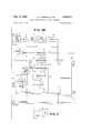
Feb. 13, 1968 w. K. FRENCH ETAL 3,369,077
PITCH MODIFICATION OF AUDIO WAVEFQRMS Filed June 9, 1964 4 Sheets-Sheet 1 All ms;
i q; D E g A;
INVENTORS WALTER K. FRENCH OLIVER W. JOHNSON, JR. BY W b- ATTORNEY w. K. FRENCH ETAL 3,369,077
PITCH MODIFICATION OF AUDIO WAVEFORMS Feb. 13, 1968 4 Sheets-Sheet 2 Filed June 9, 1964 8 I A J: 2 55E 53 5:58 E3 w 2 J M 5 a a is :5 (n GE a a a 3 3 9 95 23E 25 E :0 LI N :5 :0 a a; so: a a so: 2% M A d 0 r 0 L O 93 5 53 3 fi o E MEG 3 q 11% a QM H .TQ-
Q+ a. ame Q 3:552 3 x 58 h i v 552 H lqfvlo? 3% Q. :2 2:3; ass; N1 W $52 2:23;; 2:22 n
Feb. 13, 1968 Filed June 1964 W. K. FRENCH ETAL PITCH MODIFICATION OF AUDIO WAVEFORMS 4 Sheets-Sheet 5 1 2 18 HIGH LOW ZERO PASS -RECT. PASS CROSSING COUNTER FILTER FILTER DETECTOR 5e -GATE- 12o ADD REGISTER o 1 0 -COMPARATOR j NEGATIVE some COMPARATOR DE T E IO R REGISTER 118 Hill COMPUTER LANDJQ 11s GATE AND 410 F|G.3A FIG.
3B M30 FIG. 3
4 Sheets-Sheet i W. K. FRENCH ETAL PITCH MODIFICATION OF AUDIO WAVEFORMS Feb. 13, 1968 Filed June '3,
E! B E528 J E5; 2 E2 was: ALE 3 55:5 ms :5 T 1.... J 22:; N: 32. 42 z E :0 2% NEE A. ME xg NEE 2E Q 1 We] :3: g II E5 E: l fi O w 2 92 2 2 \F| a o 4 mo w E mm d 2 United States Patent ABSTRACT OF THE DISCLOSURE In a speech synthesizing system wherein pitch periods are adjusted according to a predetermined time base, the amplitudes of the beginnings and ends of successive adjusted periods are varied so as to eliminate discontinuities of amplitude in the composite wave form.
This invention relates to the modification of the time duration of an audio waveform and more particularly to the pitch control of an audio signal by adjusting the lengths of the pulse periods of the audio signal waveform and combining the adjusted pulses such that there are no discontinuities between pulses thereby preserving the intelligibility and quality of the information contained in the waveform.
There are many speech and communication systems which utilize prerecorded audio information for playback at desired times or upon random commands. The audio information is prerecorded on magnetic tape or other suitable storage media. If the prerecorded information was of short duration and was continuous such that it could be played back exactly as recorded, the effect on the listener would be the same as if listening directly to the speaker. In the usual case, the recorded information is made up of recordings taken at different times, and also of portions of separate messages pieced together to form a single composite message.
One example of such a system would be an automatic stock quotation system which provides an audible message giving the latest stock prices. A given stock price may be formed from a plurality of separate words prerecorded at different times. In such a situation the produced audio signal has been found to be discordant and difiicult to understand due to the change in pitch of the separate numbers and the discontinuities in the transition between separate audio signals.
It has also been found that the composite recorded signal can be made more euphonious by adjusting the pitch of each portion of the signal to a standard value and by adjusting the waveforms such that there is a smooth transition between individual segments.
The pitch of a speech sound is determined by the behavior of the vocal cords, which are more accurately described as vocal folds because of the anatomic structure. Whenever a voiced sound is uttered, the vocal folds move together and then apart in such a manner as to vary the size of the opening between them. This opening is referred to as the glottis. For a constant pitch, the vocal folds move together and separate at regular intervals. During a portion of each cycle the glottis is completely closed and the supply of air from the lungs causes a rise in pressure which reaches a maximum at this time. When the glottis opens, there is an explosive burst of air which relieves the pressure. The time interval between these bursts determines the fundamental pitch or frequency. The time interval between the pulses, that is, the pitch period, is a reciprocal function of the pitch.
Actually, an acoustical network is interposed between ice the glottis and the free air. This netwopk serves to modify the nature of the flow by superimposing higher frequencies thereon, but does not modify the pitch. As described, energy flow for producing the voiced sounds comes-in explosive bursts and, in a stretching process where the speed of playback is changed, it is inescapable that the time interval between these bursts will be changed. Thus, the resulting pitch is changed proportionally.
It is a characteristic of a periodic wave, no matter how complex that, after a certain time interval known as the period, its form is a repetition of what has gone before. In the case of an exactly periodic wave, the repetition is exact. In the case of a nearly periodic wave (and syllabic rates in speech are so slow compared with voice frequencies of interest that every voiced speech wave is periodic or nearly periodic) the repetition is inexact and approximate, but nevertheless easily recognized. References, hereinafter and in the appended claims, to periodicity of speech is intended to refer to the actual periodicity of speech; that is, to recognize that speech consists of approximately periodic portions as well as nonperiodic portions, the latter of which are processed by the system as though they were as periodic as the former portions.
Accordingly, it is a primary object of this invention to provide improved apparatus for adjusting the pitch of audio signals.
It is another object of this invention to provide apparalls for adjusting the pitch of audio signals on a time domain basis by discriminately subtracting given portions from the waveform which correspond to pitch periods of the fundamental glottal frequency of the speaker.
Still another object of this invention is to provide apparatus for substracting given portions from the pitch periods of an audio waveform such that the adjusted pitch periods have no discontinuities as a result of such adjustment.
Another object of this invention is to provide apparatus for adjusting the pitch of an audio waveform where the pitch periods of the waveform are to be shortened in accordance with a desired pitch period.
Yet another object of this invention is to provide apparatus for adjusting the length of a pitch period of an audio waveform in accordance with a desired pulse period wherein the pitch period is shortened by deleting selected portions thereof.
The foregoing and other objects, features and advan tages of the invention will be apparent from the following more particular description of a preferred embodiment of the invention, as illustrated in the accompanying drawings.
In the drawings:
FIG. 1 is a waveform diagram representative of an audio speech signal.
FIG. 2 is another waveform diagram representative of an audio speech signal.
FIG. 3 illustrates how FIGS. 3A, 3B, and 30 should be combined.
FIGS. 3A, 3B, and 3C, when combined as shown in FIG. 3, result in a schematic diagram of an embodiment of a pitch control system according to the principles of the present invention.
Referring to FIG. 1, a sample audio waveform is shown plotted along a horizontal axis representative of time and a vertical axis-representative of voltage.
The voltage range is adjusted to the range 0 to 64 volts.
However, it is desired to raise the 0 plane to the 32 volt level whereby equal variations above and below the 0 plane may be obtained. Thus, the lower unshaded portion of the waveform is 0 to 32 volts Whereas the upper shaded portion is in excess of 32 volts.
In accordance with the previous description of the fundamental or glottal frequency, and by examination of the vertical lines, a, b, 0, etc. on FIG. 1, the fundamental pitch periods are apparent. Thus, the waveform between the lines a and b is almost the same as the waveform be tween the points b and c and between the points c and d. Also, the length a-b is approximately equal to the length bc, which is approximately equal to the length c-d, etc. Since the length of the pitch period is representative of pitch, the pitch of the entire Waveform is uniform. Likewise, the transition of the waveform from the end of one pitch period to the beginning of the next pitch period is smooth and continuous.
Referring to FIG. 2, a situation is graphically depicted wherein one sound is to follow another sound in a constructed waveform. Two conditions are obvious; first, the pitch period e-f is shorter than the pitch period gh resulting in a lower pitch sound following a higher pitch sound and second, the waveform level at is of different amplitude than the waveform level at g resulting in a discontinuity when the waveforms are joined.
These two undesired conditions are overcome by the system to be described. The pitch of the total audio waveform is made uniform by adjusting each pitch period to agree with a desired pitch period. Initially the actual input waveform is stored and the beginning and ends of the pitch periods thereof are determined. If the actual pitch period is found to be greater than the desired pitch period, an amount equal to the difference is removed from the end of the actual pitch period.
The pitch periods of the input waveform, now being equal to the desired periods are then joined together. The dilference in amplitude between the end of the waveform of one pitch period and the beginning of the waveform of the succeeding pitch period is determined and a DC. ramp function is formed which, when added to the first waveform, will adjust the amplitude of the end of the first waveform to be equal to the beginning of the suceeding waveform thereby providing a relatively smooth transition.
The first operation to be performed by the system is to determine the beginnings of the pitch periods of the audio waveform signal under consideration. The beginnings of the pitch periods are characterized in that the audio waveform at such point has a maximum positive to negative swing. In the present system the audio waveform is maintained in a storage device and is scanned such that the analog values of the peak to peak transitions are stored. Each peak to peak transition is compared with the next peak to peak transition and the greater of the two is retained for comparison with successive peak to peak transitions until, after a given length of waveform has been scanned, the maximum analog peak to peak transition is retained in a storage circuit and the point of occurrence of such maximum peak to peak transition is specified by a value in a counter.
The maximum peak to peak transitions represent the start of each period of the audio waveform. Each actual pitch period of the audio waveform is then entered into a register and compared in length with a desired pitch period value, whereby the amount to be removed from each actual pitch period is determined. The actual waveforms are shortened by gating them through a gate circuit which opens at the beginning of the actual pitch period and which then closes at a time equal to the desired pitch period. The end of each actual pitch period of the Waveform will then abruptly terminate at some random amplitude. Each the shortened actual pitch periods could then rejoin to form a continuous waveform, however, the amplitudes of the end of one adjusted pitch period and the beginning of the next adjusted pitch period may not be necessarily at the same amplitude, but will be as depicted by 1" and g in FIG. 2. To make the waveform smooth and continuous, the present system determines the amplitude differences between the beginning and the end of the adjusted pitch periods and adds or subtracts a ramp voltage to the end of each adjusted pitch period to raise or lower the amplitude of the end of each adjusted pitch period to be equal with the amplitude of the beginning of the next adjusted pitch period.
An embodiment of a system for carrying out the aforesaid functions is shown in the combined FIGS. 3A, 3B,. and 3C. In explaining the operation of FIGS. 3A, 3B, and 3C certain functions are required, such as signal comparisons, signal storage, timing, etc. In the explanation of FIGS. 3A, 3B, and 3C it will be obvious to one skilled in the art that these functions may be carried out by 3. variety of well known circuit elements. In the interest of simplicity a general purpose computer 3 has been included in the system and will represent the means for carrying out some of the more well known arithmetical and super-' visory operations. Any well known general purpose computer having a memory storage and an arithmetic unit under program control will sufice for computer 3.
In FIGS. 3A through 3C audio input 2 provides a source of speech signal, Ganged switch 4 is normally open. When ganged switch 4 is closed, a synchronizing signal is produced by single shot circuit 6 which enters recirculating storage device 8 along with the audio signal from audio input 2. The synchronizing signal and the audio signal are stored on separate tracks. After a predetermined time interval, switch 4 reopens and segment of audio waveform preceded by a synchronizing signal on a separate track continue to circulate in storage device 8.
The continually circulating audio waveform will be selectively employed for various purposes. Initially, the audio waveform from recirculating storage device 8 is applied to a circuit which establishes a time period during which the said audio waveform will be scanned for the presence of a beginning of a pitch period, as manifested by a peak to peak maximum of the audio waveform within the scanned period.
Establishing the gl ttal period The period during which the audio signal is scanned for a peak to peak maximum is referred to as the glottal period, that is, a period long enough to insure the occurrence of the beginning of a pitch period (as represented by a peak to peak maximum) yet not too long so as to include the next pitch period beginning. To determine this period the audio signal in delay line 4 is cycled once and applied as an input signal to a high pass filter 10 which removes the low frequency components. The high frequency component signal is then applied to rectifier 12 which produces an output signal which is the envelope of the high frequency components. The signal is then passed through a low pass filter 14 which removes the high frequency components, leaving only the envelope of the signal. The envelope of the signal generally resembles a triangular waveform; first increasing and then decreasing. The glottal period is determined by the zero crossings of the positive going portions of the waveform.
Thus, the output signal from low pass filter 14 is applied to a zero axis crossing detector 16 which generates an output signal only upon the occurrence of positive going zero axis crossings of the envelope. The output of zero axis crossing detector 16 is applied to a counter 18 which will begin to count upon the occurrence of the first positive going zero axis crossing and stop upon the occurrence of the next positive going zero axis crossing.
A period is therefore established in counter 18 from zero to a count which what will be referred to as T This period is an approximate representation of the glottal period. Another operation which occur during the first cycle of the audio waveform in storage device 8 is that the synchronizing signal in the storage device 8 is applied, through a synchronizing signal detector 20 to counter 22. Counter 22 is also connected to a continually running oscillator 24 which causes the counter 22 to continually count. The synchronizing signal from synchronizing detector 20 resets the counter 22 so that a count from zero begins immediately after the occurrence of the synchronizing signal at each cycle of storage device 8. Sometime after the occurrence of the synchronizing signal a voiced audio signal will occur. The present invention relates to pitch adjustment, and pitch is a characteristic of voiced rather than fricative sounds. Therefore, the output of storage device 8 is applied to a voicing detector 26 which produces an output signal upon the occurrence of voiced audio signals from storage device 8. The signal from voicing detector 26 is applied to a gate circuit 28 which gates the count of counter 22 at the time of the voiced sound into a register 30. The count in counter 22 at the beginning of the voiced sound will be referred to as T The signal from voicing detector 26 at count T is also applied to a gate circuit 32 at the output of counter 18 to gate the glottal period count T into an add circuit 34 where it is added to the T count from counter 22 and stored in register 36. Thus, during the first cycle of the audio waveform in delay element 4 the following steps are performed. First, an approximate glottal period T is established in the form of a count in counter 18, counter 22 is set to zero by the synchronizing signal in storage device 8 and the later count T at the time of the beginning of voiced signals is read into register 30 and a count equal to the beginning of voiced signals T plus the count T from counter 18 is read into register 36. Thus, registers 30 and 36 contain counts which differ in the amount equal to the glottal period count T It is to be noted that the output of counter 22 is connected to a first comparator circuit 38 which is in turn connected to register 30' and to a second comparator circuit 48 which is in turn connected to register 36. Thus, the count of counter 22 may be compared with the counts set in both register 30 and register 36.
Determining the pitch periods Upon the second cycle of storage device 8 the system is ready to determine the beginning of a pitch period by determining the time of occurrence (via a count in counter 22) of the maximum peak to peak difference of the audio Waveform signal in the period between the beginning of the voiced audio signal T as set in register 30 and the time count T -i-T g as set forth in register 36.
During the second cycle of the storage device 8 the second occurrence of the synchronizing signal resets the counter 22 to zero and oscillator 24 begins the new count. When counter 22 reaches the count T a match occurs with the contents of register 38 through comparator 38 causing an output signal from comparator 38 which is coupled to a flip-flop circuit 42. An output signal thereby results from the 1 side of fiip-fiop 42 which will be referred to a the Q signal.
The Q signal from flip-flop 42 is applied directly to a gate circuit 44. The output from voicing detector 26 is also applied to gate circuit 44, thus gate circuit 44 opens (on the second cycle) at a time count of T The Q signal from flip-flop 42 is also applied to analog hold circuits 46, 43, 50, and 52 (to be later described) to clear or erase any analog signals therein. The output of flip-flop 42 is also applied to a circuit 54 for detecting a negative going signal change (for example, a diiferentiator in series With a reversed diode) to produce a signal at the end of the Q pulse to be later explained.
The output of recirculating storage device 8; i.e., the
speech signal segment, is conducted through gate 44, and as previously stated, is applied to analog gates 56, 58, 60, and 62. As will be described in detail, the gate circuits 56 and 58 are employed to gate one pair of positive and negative analog waveform peaks into analog hold circuits 46 and 48 respectively, and gate circuits 60 and 62 are used to gate another pair of positive and negative analog peaks into analog hold circuits 50 and 52 respectively. The registers 68 and 70 store the times (in the form of a count) at which the positive peaks occur. The amplitudes of the peak to peak analog voltages (that is, the difference between the positive and negative peaks) are compared by other circuitry.
The output signal from synchronizing detector 20' is also applied to a fiip-flop circuit 72 to set the 1 output of flip-flop 72 to the high level state upon the occurrence of the synchronizing signal. The output signal on the 1 bit output lead of flip-flop 72 will be hereinafter referred to as signal 101. I
The 1a signal from flip-flop 72 is applied, among other places, to analog gate 56. Thus, upon the occurrence of the first positive peak of the audio signal stored in storage device 8 following the synchronizing signal, the +p signal from peak detector 64 being applied to gate circuit 56, will open gate circuit 56 and permit the analog value of the positive peak to be stored in analog hold circuit 46.
The 1a signal from flip-flop 72 and the -[-p signal from peak detector 64 are also applied to gate circuit 74 between counter 22 and register 68 so that the occurrence time (in the form of a count) of the +p signal is stored in register 68. The 1a signal from flip-flop 72 is further 7 applied to OR circuit 76, the output of which is applied to AND circuit 78 along with the +p signal from positive peak detector 64 to provide an output signal from AND circuit 78 to set a flip-flop circuit 80. When flipflop circuit 80 is set, an output signal is provided on the 1 bit output lead 82 which is in turn applied to delay circuit 84, AND circuit 86, and AND circuit 88. Signal In from flip-flop 72 is also applied to AND circuit 86 which therefore produces an output signal hereinafter referred to as signal 112. The signal 112 from AND circuit 86 is applied to analog gate circuit 58 so that upon the occurrence of the following negative peak of the audio signal the resultant negative peak signal -p from negative peak detector 66 gates the analog value of the negative peak to analog hold circuit 48 and is then compared with the analog of the positive peak in analog hold circuit 44 at differential amplifier 90.
The output of differential amplifier 90 is the peak to peak value of the first positive to negative excursion of the input audio voiced signal. The output signal from differential amplifier 90 is inverted by inverter circuit 92 and is applied to analog add circuit 94. Circuits 46 and 48 being analog hold circuits, the signal applied to add circuit 94 is maintained until such time as a new signal is applied through gate 56 and/or 58. At this point in the discussion there is no output as yet from the diiferential amplifier 96 since the necessary gating signals 2a and 2b for gates 60 and 62 (to be later described) have not yet been generated. Therefore, analog hold circuits 50 and 52 are still at their initial zero level. Thus, the only input to add circuit 94 is the negative signal from inverter circuit 92. The output signal from add circuit 94 is therefore also negative and will be conducted through a reversed diode 96 to a gate circuit 98.
In the meantime the 1b signal from AND circuit 86 ceases since the signal on lead 82 of flip-flop (it) is fed back to reset flip-flop 80 through a delay circuit 84 (which provides a delay sufiicient to allow the analog value in hold circuit 48 to be established).
The In and 1b signals no longer being present, gate circuits 56 and 58 will remain closed as well as gate circuit 74, during the occurrence of the next positive and negative peak signals of the voiced analog waveform. The next positive peak of the analog waveform Will produce another +p signal from positive peak detector 64 which is applied to gate circuits 58, 6t and 62 and gate circuits 74 and 104. The gate circuit 104 is located between counter 22 and register 70. The 2a signal from flipflop 72 is now present so that gate circuits 60 and 1% are opened. The opening of gate circuit 69 allows the analog positive peak of the audio waveform to enter analog hold circuit 50 and the opening of gate circuit 104 permits the time of occurrence count of this positive peak to be stored in register 70.
The 2a signal from flip-flop 72 is also applied to OR circuit 76, the output of which is gated with the +p signal at AND circuit 73 to switch flip-flop 80 which in turn will again provide an output signal on lead 82. The output signal on lead 82 will be gated with signal 2a at AND circuit 88 to provide an output therefrom which will be referred to as signal 212. A 112 output signal will not be produced by AND circuit 86 because the necessary 1a signal is not present at the input thereof. Signal 2b is applied to gate circuit 62 along with the output of negative peak detector 66 so that upon the occurrence of the next (second) negative peak of audio waveform, a -p signal from peak detector 66 is produced which will gate the negative peak analog signal into hold circuit 52.
The 2b signal also ceases by the action of the signal on lead 82 Of flip-flop 80 being fed back through delay circuit 84 to reset flip-flop 80, thereby disabling AND circuit 88. The delay circuit 84 again provides a delay sufiicient to allow the analog value to be established in hold circuit 52. Hold circuit 50 (containing the second positive peak analog signal) and hold circuit 52 (containing the second negative peak analog signal) are coupled to a differential amplifier 96 which provides an output signal equal to the peak to peak value of the second positive and negative waveform peak signals. The output signal from differential amplifier 96 is applied to add circuit 94 where it is compared with the inverted peak to peak analog value of the first positive and negative peaks of the audio waveform from differential amplifier 90 (via inverter 92). The output signal from inverter circuit 2 will either be greater than the output signal from differential amplifier 96 in which case the output signal from add circuit 94 will be negative, or will be less than the output signal from amplifier 96, in which case the output signal from add circuit 94 will be positive. If the output signal from add circuit 94 is negative, it means that the peak to peak value of the first positive to negative transition of the audio waveform (the output of differential amplifier 99) is greater than the peak to peak value of the second positive to negative transition of the audio waveform (the output of difierential amplifier 96). This means that the first and second peak signals may represent the beginning of a pulse period and that the second peak to peak signals do not. In such instance it is desired to continue to hold the values in hold circuits 46 and 48 and to store the third positive and negative peaks of the audio signal in hold circuit 50 and 52 (in place of the second positive and negative peaks) and compare the difference (output of amplifier 96) With the first positive to negative peak difference, and so on until the value of the first positive to negative peak transition is exceeded or until the end of the sampling period.
If the second positive to negative peak transition does exceed the first (i.e., the output of add circuit 5 4 being positive), the initial peak to peak transition of the audio waveform is smaller than the second peak to peak transition and is not representative of the beginning of the pitch period. Thus, the second peak values are held in hold circuits 5i) and 52 and the third positive and negative peak values of the audio signal are stored in hold circuits 46 and 48 for comparison therewith.
The general operation of this portion of the system is therefore to store the first peak to peak analog value of the audio waveform in a first hold channel and compare such value with subsequently occurring peak to peak analog values which are entered into a second hold channel. The initial peak to peak value in the first hold channel will remain stored until a peak to peak value in the second hold channel exceeds it in value, at which time the new maximum peak to peak value remains stored in the second hold channel and further subsequently occurring peak to peak values are entered in the first hold channel (replacing the initial peak to peak values previously stored) for continued comparison. Thus, at the end of the glottal period as set forth by the values in registers 39 and 36, a maximum peak to peak transition of the audio waveform will be determined which will in turn determine the beginning of the pitch period of the sound.
For example, if the second peak to peak transition were greater than the initial transition, the output from add circuit 94 will be positive and pass through diode 106 and be applied to gate circuit 1% where it will be gated by the still present 2a signal (note, if the output from add cricuit 94 were negative it would indicate that the initial peak to peak transition was larger and such signal would pass through diode 96 to gate 98 which does not become gated since signal In is absent). The signal gated through gate 108 is applied to gate circuit 100 where it is gated by the p signal produced by the second negative peak signal which has been delayed by delay circuit 102. Delay circuit m2 provides a delay sulficient to allow the values in the analog hold circuits 46, 43, 5t and 52 to be established. The signal gated through gate circuit 100 is applied to flip-flop 72 to switch it to its original state, that is, to provide the 1:: signal so that the next (third) positive and negative analog peak signals are stored in hold circuits 46 and 48. If, however, the initial peak to peak transition had been larger than the second transition and the output of add circuit were consequently negative, then it can be seen that no such negative signal would not be passed through gate 41 due to the absence of the la signal and no switching signal would be applied to flipfiop 72. Signal 2a would, therefore, remain present. Thus, the third positive and negative analog peak signals would be entered into hold circuits 50 and 52 for comparison with the initial peak to peak transition.
In like manner each subsequent peak to peak transition of the voiced audio waveform will continue to be compared With the previously stored most maximum peak to peak transition and if greater, will displace the previous stored maximum value in the analog hold circuits and will itself be compared with further occurring peak to peak transitions. Counter 22 will continue to run until it reaches the value T +T which is the value stored in register 36. At this time a compare signal is generated by comparator circuit 48' which is applied to and switches flip-flop 42, causing the Q output signal therefrom to drop. The dropping of the Q signal results in gate 44 closing a no further audio waveform being applied to gates 56, 58, 60, or 62.
The 1 output of hip-hop 42 is also applied to circuit 54 for detecting the decreasing or lagging edge of the Q signal. Circuit 54 may, for example, include a differentiating circuit and a reversed diode. The signal is produced from circuit only at the end of the Q pulse.
2 The signal from circuit 54 is used to read out the time count at which the maximum peak to peak transition of the audio waveform occurred. There will be a count in register 68 and a count in register 78, one of which represents the count of the time of the maximum peak to peak transition of the audio waveform and therefore the beginning of a pitch period.
If flip-flop 72 is in its first state such that signal 10 is present, then the count in register 68 represents the pitch period beginning, but if flip-flop 72 is in its second state such that signal 2a is present, then the count in register 70 represents the pitch period beginning. Thus, the signal from circuit 54 is connected along with the 1 output lead of flip-flop 72 to an AND circuit 116, the output of which is coupled as a read-out signal to register 68. The output lead of flip-flop 72 is connected along with the output of circuit 54 to an AND circuit 112, the output of which is coupled as a read-out signal to register 70. At the end of the Q pulse therefore, if the la signal is present, register 68 is read out, and if the 2a signal is present, register 70 is read out.
Whichever register is read out, a count will be provided which represents the time of occurrence of the first pitch period beginning thus far detected.
This count will be referred to as T and will fall somewhere between the counts T and T +T As previously stated, at the end of the Q pulse (time T +T the T count is read out of either register 68 or register 70. This T count is applied to and stored in the computer 3 via leads 114 or 116, where a computation is performed such that to the T count is added onehalf the glottal period count T to produce the value T /2T A second computation is performed wherein one and one-half the glottal period T is added to T to produce the value T T These values having been completed, they are applied from the computer 3 to registers 39 and 36 via leads 118 and 120 respectively with the values T -i- /zT being stored in register 36 and the value T IQT being stored in register 36.
What has occurred has been the selection (in the form of a count) of the beginning of a pitch period within the audio waveform as the stored audio waveform was cycled once in storage device 8. The location of the beginning of the pitch period T was, by predesign, located in the glottal period between T and T +T With the beginning of this pitch period at T established, the beginning of the next pitch period will be located, and will be looked for within the period between T -i- /zT (stored in register 30) and T +T (stored in register 36) because the beginning of the second pitch period will be located approximately in the middle of this period.
Nothing further happens in the system until the cycle of the storage device 8 ends and a new cycle begins. At the beginning of the new cycle of storage device 8 the synchronizing pulse preceding the audio Waveform resets counter 22 and sets flip-flop 72 such that a la signal is present on the 1 output lead thereof. As before, the 10 signal is applied to gate circuits 56 and 74.
The counter 22 will continue to count until a value T /2T is reached, this being the count stored in register 3%). At this time a compare signal is generated by comparator circuit 38 which switches flip-flop 42 such that a Q signal again appears on the 1 output lead thereof. The Q signal from flip-flop 42 is applied to and clears analog hold circuits 46, 48, Si), and 52 and is applied to and opens gate circuit 4 The opening of gate circuit 44 permits the voiced audio waveform from storage device 8 to pass therethrough and be applied to gate circuits 56, 58, 60, and 62, and peak detectors 64 and 66. This, as previously stated, occurs at a time count of T /z T The next positive peak thereafter occurring will produce a +p output signal from peak detector 64 which is applied to gate 56 and, the la signal being present, gate 56 is opened and the analog value of the positive peak is stored in hold circuit 46.
As described for the previous cycle, the la signal also passes through OR circuit 76 and is gated by the +p signal through AND circuit 78 to switch flip-flop St). A signal is thereby produced on lead 82 which is gated by the la signal at AND circuit 86 to produce a 11) signal at the output thereof. The 1b signal is applied to gate circuit 58. The next negative peak of the audio waveform will generate a p signal from peak detector 66 which will be applied to and open gate circuit 58 so that the analog value of the negative peak will pass therethrough and be stored in analog hold circuit 48. The peak to peak value of the audio waveform is then produced by differential amplifier 90.
The output signal from differential amplifier 90 is inverted by inverter circuit 92 and applied to analog add circuit 94 where it is compared with the output signal from differential amplifier 96 (which is zero at this time). Thus, the output signal from add circuit 94 is negative and will pass through diode 96 and be applied to gate circuit 98.
In the meantime the 1b signal from AND circuit 86 ceases since the signal on lead 82 of flip-flop 80 is fed back to reset flip-flop 80 through the delay circuit 84.
The In and 1b signals no longer being present, gate circuits 56 and 58 will remain closed as Well as gate circuit 74, during the occurrence of the next positive and negative peak signals of the voiced analog waveform. The next positive peak of the analog waveform will produce another +p signal from positive peak detector 64 which is applied to gate circuits 56, 58, 60, and 62 and gate circuits 74 and 104. The 2a signal from flip-flop 72 is now present so that gate circuits 66 and 104 are opened. The opening of gate circuit 6t) allows the analog positive peak of the audio waveform to enter analog hold circuit 50, and the opening of gate circuit 104- permits the time of occurrence count of this positive peak to be stored in register 70. The 2a signal from flip-flop 72 is also passed through OR circuit 76, gated through AND circuit 78, switches flip-flop 8i thereby resulting in a signal on lead 82. The signal on lead 82 is gated through AND circuit 88 by the 2a signal from flip-flop 72 and a 2b output signal is produced at the output of AND circuit 83. The 2b signal is applied to analog gate circuit 62 so that when the next negative peak of the audio waveform produces a p signal from negative peak detector circuit 66, gate circuit 62 opens and the analog value of the negative peak of the audio waveform will be stored in analog hold circuit 52. The difference between the positive and negative peaks stored respectively in hold circuits 50 and 52 is produced by differential amplifier 96. The output signal from differential amplifier 96 is applied to add circuit 94 where it is added with the inverted negative signal from differential amplifier 90.
The circuit then operates as previously described, that is, the largest peak to peak difference is retained in the hold circuits and compared with successive peak to peak values until a larger value is found. The only difference in the present cycle and the previous cycle is that the audio waveform is scanned between the time counts of T -i /zT and T T whereas in the previous cycle the audio waveform was scanned between the time counts of T and T,,+T
aseaow When counter 22 reaches the time count T 7 T it compares with the count in register 36 and a compare signal is generated by comparator circuit 46 which switches flip-flop 42 such that the Q signal therefrom closes.
The end of the Q signal causes gate circuit 44 to close and a signal to be produced by negative going signal detector circuit 54 which is gated with the la signal or the Zn signal (whichever present) at AND circuits 110 and 112 and will read out the count in the proper one of registers 68 and 7d. The count thus read out will represent the time of occurrence of the positive peak of the largest peak to peak audio waveform value in the period from T /2T to T T and consequently will be the time of occurrence of the beginning of the second pitch period. This time count will be referred to as T The T time count read out of either register 68 or 78 is applied to and stored in the computer 3 via the associated ones of leads 114 and 116, where a computation is performed such that to the T count is added one-half the glottal period count T to produce the value T /2T A second computation is performed wherein one and one-half the glottal period T is added to T to produce the value T +%T These values are then transmitted from the computer to registers 57 and 58; register 57 having the T /z T value stored therein and register 58 having the T ,T value stored therein.
In a manner identical to that previously described, on the next cycle of storage device ii the voiced audio waveform is scanned in the period between T -t- /zT and T +%T g for a maximum peak to peak value which represents the beginning of the next pitch period. Such next pitch period beginning time count, referred to as T is stored in the computer 3 and a new scan period T +V2T to T 7 T is established Within which the next pitch period beginning T is determined. Ultimately, the entire waveform stored in storage device 8 will be scanned and a series of time counts T T T T T representng the beginnings of all of the pitch periods are stored in the computer 3.
The time distance between each of the pitch period beginnings are the actual pitch periods which determine the pitch of the sounds. The various pitch periods, that is, T1 to T2, T2 to T3, T3 to T4, T4 to T5, etc. differ in length. As previously stated, these pitch periods will be adjusted to a uniform length equal to a desired pitch period referred to as T Establishing desired pitch periods During this phase of system operation a given amount of waveform from each pitch period will be removed or cut-off to shorten each pitch period to agree with the desired pitch period T Due to this end of period waveform cut-off, the end of one pitch period waveform and the beginning of the next pitch period may be discontinuous. For example, the amplitude levels may differ as illustrated by points and g in FIG. 2. Thus, in addition to shortening given pitch periods to agree with T the amplitude of the ends of waveforms may have to be raised or lowered to the level of the beginning of the next successive pitch period waveform.
As a practical matter, the value of the desired pitch period T may be selected as equal to the smallest of the actual pitch periods T to T T to T T to T etc. This will insure that each of the actual pitch periods will be either equal to or greater than the desired pitch period.
In the following description all of the pitch periods will be adjusted to conform to a single desired pitch period T however, it might also be possible that the different pitch periods might be adjusted to conform to different desired pitch periods; for example, one desired pitch period may be employed for open vowel sounds and another desired pitch period may be provided for closed vowel sounds. The use of more than one desired i2 pitch period would require minor modifications in the system of FIG. 3.
As will be seen from the following discussion, the recirculating storage device 8 continues to cycle after the determination of all the pitch period beginning T through T On the first cycle after the determination of T the amplitude difference between the end of the first desired pitch period at T +T and the beginning of the next pitch period at T is determined. On the second cycle of storage device 3 after the determination of T a ramp function of the amplitude difference is added to the first desired pitch period waveform, which is then stored in computer 3. On the third cycle of storage device 8 after the determination of T the amplitude difference between the end of the second desired pitch period at T +T and the beginning of the third pitch period at T is determined. On the fourth cycle after the determination of T this amplitude difference is :added to the second desired pitch period waveform and the second adjusted desired pitch period waveform is stored in computer 3. In like manner the rest of the adjusted desired pitch period waveforms are constructed on successive even cycles and stored in computer 3.
A more detailed discussion of this operation now follows.
On the next cycle of the storage device 8 after the determination of the final (T pitch period beginning, the counter 22 is again reset to zero by the synchronizing pulse from storage device 8. It is to be noted that the output from recirculating storage device 8 is applied to a gate circuit 122 which is controlled by a flip-flop circuit 124. When the flip-flop 124 is in its 1 state gate 122 is opened. Flip-flop 124 is switched by a signal from computer 3. The flip-flop 124 is set to its 1 state by a signal on lead 123 and to its 0 state by the signal on lead 1% delayed an amount T by delay circuit 128. The output of counter 22 is fed into computer 3 for comparison with the pitch period beginning counts T T T T T When the counter 22 reaches the count T it compares with the count T stored in the computer 3 and a pulsed signal is produced from the computer 3 on lead 126 to set flip-flop 124 to its 1 state, thereby opening gate 122 and permitting the audio waveform from storage device 8 to pass therethrough. The pulse on lead 126 is delayed an amount T by delay circuit 128, thus the flip-flop 124 is switched to its 0 state at a time T +T When flip-flop 124 is switched to its 0 state gate 122 is closed. It is seen that gate circuit 122 was open for the period T through T +T The audio waveform was passed therethrough for this period so that a portion of audio waveform is produced at the output of gate circuit 122 which begins at the pitch period beginning T and continues for the desired pitch period T This waveform portion, which has the desired pitch period T is applied to an add circuit 139, which is in turn connected to the input of an analog to digital converter 132. During this first cycle of the storage device 8 (from T to T -l-T and each successive odd cycle the output from analog to digital converter 132 is inhibited by a signal from computer 3. The pulse from delay circuit 128 occurring at time T +T is also applied to an analog gate circuit 134 which gates the analog value of the audio waveform at the time T +T to an analog hold circuit 136. A short time after time T +T the counter 22 will reach the count T The count T compares with the T value stored in computer 3 and a pulse is produced on computer output lead 138 to momentarily open analog gate 14%, which gates the analog value of the audio waveform to analog hold crcuit 142. The analog value of the audio waveform at time T +T (the end of the first desired pitch period) stored in hold circuit 136, and the analog value of the audio waveform at time T (the beginning of the next pitch period) stored in bold circuit 142 are compared in a different amplifier 144, the output of which is the difference between the two analog values. The output of differential amplifier therefore is the amplitude difference between the audio waveform at the end of the first desired pitch period and the beginning of the second pitch period. This difference voltage is referred to as V The difference voltage V is applied to an integrating circuit 146 consisting of an input resistor 148, an operational amplifier 150 with feedback capacitor 152, the output of which is connected to ground potential through a normally closed switch 154. Switch154 is connected to a solenoid 156 which is in turn actuated the pulsed signals on leads 126 and the pulsed signals T occurring later from delay circuit 128. Thus, switch 1'54 is normally closed, is opening at time-r T and closes again at time opens again at T and closes at time T +T etc. The resultant output of integrating circuit 146 is a ramp voltage which begins at zero at the beginning of each pitch period T T T etc. and which builds up to the associated value of voltage V at a time T later. During this presently described cycle what has occurred is that a segment audio waveform has been passed through gate circuit 122 betwen the times T and T -i-T This segment of waveform is applied through add circuit 130 to the digital to analog converter 132 which is inhibited for this first present cycle (and for all successive odd number cycles). At time T +T the analog value of the amplitude of the audio waveform at this time is stored in hold circuit 136 and at time T the analog value of the audio waveform at this time is stored in hold circuit 142. The difference be tween the two amplitudes(V is determined and applied to integrating circuit 146.
The circulating storage device 8 completes its cycle with nothing further occurring. On the next (second) cycle of the storage device 8 counter 22 is reset and recounts. At time T the signal from computer 3 on lead 126 switches flip-fiop 124 thereby opening gate 122 allowing the audio waveform to pass therethrough. At the same time switch 154 of integrator circuit 1'46 is opened so that the ramp voltage output thereof begins to build. The output of integrator circuit 146 is applied to add circuit 130 and with the audio waveform from gate 122. The audio waveform is applied to add circuit 130 for the period T to T -l-T During this period the output signal from integrator circuit 146 increases from zero at T to V at T +T Thus, the output signal from add circuit 132 is the audio waveform with a desired pitch period at T and and amplitude at time T +T d increased by an amount V so that it is the same amplitude as the beginning of the next pitch period at time T This being an odd cycle of the storage device 8, the inhibit signal at the output of the analog to digital converter 132 is removed and an output signal is produced therefrom which is the digital equivalent of the audio waveform during the first desired pitch period T to T +T d with the voltage adjustment V added thereto. This digital output signal is transmitted to computer 3.
On the next cycle of storage device 8 the second desired pitch period waveform is for-med and the amplitude of the end thereof is adjusted to equal the beginning of the third pitch period. When counter 22 reaches t a pulse is generated by the comparison with the value T in computer 3 and this pulse is transmitted on lead 126 to switch flip-flop 124 to its 1 state. The flip-[flop 124 opens gate 122 and permits the audio waveform to pass through until time T +T when the delayed pulse through delay circuit 128 switches flip-flop 124 to its state and gate 122 closes. Thus, a second waveform segment beginning at time T and ending at a period T later is passed through gate 122 to add circuit 130 and to analog to digital converter 132. Analog to digital converter is inhibited on this cycle and no output signal therefrom is produced. At time T -i-T the output pulse from delay circuit 128 open analog gate circuit 134 entering the analog value of the audio waveform at time T +T into hold circuit 136. A short time after the occurrence of time T +T c0unter 22 reaches the count T value and compares with the T value in computer 3. A pulse is then generated on lead 138 which opens gate 140, allowing the analog value of the audio waveform at time T to enter hold circuit 142. The amplitude of the audio waveform at the end of the second desired pit-ch period (T +T is then compared with the amplitude of the audio waveform at the beginning of the third pitch period T by means of differential amplifier 144 is another difference voltage V and is applied to integrator 146.
The present cycle of the recirculating storage device continues with no further effect and at the beginning of the next cycle counter 22 is reset. At time T of this next cycle gate 122 is opened and the segment of audio waveform signal is passed through to add circuit 130. Also at this time T switch 154 of integrator 146 is opened and the output of integrator 146 begins to increase in voltage. The increasing voltage from integrator circuit 146 is added to the audio wave-form signal at add circuit until time T +T at which time the value added to the audio waveform signal is V and at which time gate 122 is closed and switch 154 is closed. The output from analog to digital converter 132 is not inhibited at this cycle so that a digital representation of the second desired pitch period with adjusted amplitude is produced as an output signal and transmitted to computer 3.
In like manner on successive odd cycles the remainder of the audio waveform is gated through gate 122 between the beginning of each of the rest of the pitch period beginnings T T T for a time period equal to T such that the voltage difference between the end of one desired pitch period and the beginning of next pitch period (i.e., voltage V may be calculated. On successive even cycles the amplitude differences (V between the waveforms at the end of each pitch period and the beginning of the next pitch period so determined are added to the audio waveform signal so each pitch period is adjusted by the addition of a voltage which results in the ends of the pitch periods and the beginnings of the next pitch periods being at the same amplitude. The adjusted desired pitch periods so produced on the successive even cycles are converted to digital representation by analog to digital converter 132 and 'are transmitted to computer 3.
The digital inputs to the computer 3 from analog to digital converter 1.32 is the audio waveform having pitch periods of desired length and adjusted so the end of each pitch period is at the same voltage amplitude as the beginning of the next pitch period. As previously stated, these pitch periods are constructed on every other cycle of the recirculating storage device during this phase of the operation. Thus, the pitch period input signals to computer 3 are spaced in time and form a continuous waveform. The butting or joining together of the separate pitch periods in digital form may take place in computer 3 which has the suitable storage and switching units for this purpose.
Thus, it is seen that a complete audio signal is stored in computer 3 in digital form. Each of the pitch periods stored in digital form in the computer have pitch periods equal to the desired pitch period T and do not have any discontinuities between the ends and beginnings of successive pitch periods. The stored audio signal may be read out of the computer 3 and stored as an audio signal on magnetic tape for practical use.
What has been described is a system wherein segments of different audio waveforms may be combined together to form a single audio waveform or message. In order to overcome the pitch changes between segments, each pitch period of the composite audio waveform is made to conform or be equal to a selected standard pitch period. At the same time the amplitude differences between the ends and the beginnings of the separate pitch periods 15 are compensated for by the addition of calculated ramp voltages. The resultant audio waveform will be of uniform pitch and have no discontinuities and will sound normal to the human ear.
While the invention has been particularly shown and described with reference to a preferred embodiment thereof, it will be understood by those skilled in the art that various changes in form and details may be made therein without departing from the spirit and scope of the invention.
What is claimed is:
1. A system for modifying audio data signals comprising:
means for combining discrete increments of audio data into a composite signal,
means for processing said composite signal for determining successive periods within said data signal, means for determining the lengths of each period of said data signal, means for adjusting the lengths of each period of said data signal to at least one desired period length,
means for determining the amplitude of the beginning and ends of said length adjusted periods of said data signal,
and means for adjusting the amplitude of the end of each of said length adjusted periods of said data signal to equal the amplitude of the beginning of each successive length adjusted period.
2. A system for modifying audio data signals comprising:
means for combining discrete increments of audio data into a composite signal,
means for processing said composite signal for determining successive periods within said data signal, means for determining the lengths of each period of said data signal, means for adjusting the lengths of each period of said data signal to at least one desired period length,
means for determining the amplitude of the beginning and ends of said length adjusted periods of said data signal,
means for adjusting the amplitude of the end of each of said length adjusted periods of said data signal to equal the amplitude of the beginning of each successive length adjusted period,
and means for recombining said amplitude and length adjusted periods of said data signal into a composite signal.
3. A system according to claim 2 wherein said successive periods of said data signal are selected to be the pitch periods of the data signal.
4. A system according to claim 2 wherein said means for adjusting the amplitude of the end of each of said length adjusted periods of said data signal includes:
means for comparing the amplitude of the end of each of said length adjusted period with the plitude of the beginning of the next successive period, means for producing an amplitude signal difference representative of each of said comparisons,
means for generating an adjustment signal for each of said comparison, said adjustment signals being a function of said amplitude difference signals,
and means for adding said adjustment signals to the associated ones of said length adjusted periods of said data signal.
5. A system for modifying audio data signals comprising:
means for combining discrete increments of audio data into a composite signal,
means for analyzing said composite data signal for determining the maximum peak to peak amplitude differences Within selected regions of said data signal, said maximum peak to peak amplitude difiierences representing each successive pitch period length, means for comparing each of said pitch period lengths with a desired pitch period length and adjusting each pitch period to conform with the desired pitch period length,
means for determining the amplitude of the beginning and end of each of said length adjusted pitch periods,
and means for adjusting the amplitude of the end of each of said length adjusted pitch periods to equal the amplitude of the beginning of each successive length adjusted pitch period.
6. A system according to claim 5 wherein said means for analyzing said data signal for determining maximum peak to peak amplitude differences within selected regions of said data signal includes:
means for storing and comparing the peak to peak amplitude differences within selected successive regions of said data signal for determining the maximum peak to peak amplitude difference within each of said successive selected regions,
counter means synchronized with said storing and comparing means for providing a count representative of each positive peak associated with said maximum peak to peak amplitude differences with said selected regions,
means for establishing a plurality of equal length regions within said data signal, each equal length region beginning with each of said positive peaks associated with said maximum peak to peak differences and ending at a position prior to the next positive peak of the next successive maximum peak to peak transition,
means for processing said equal length regions of said data signal for producing a separate dilference sig' nal representative of the amplitude difference of the data signal between the end of each equal length region and the beginning of the next successive equal length region,
means for adjusting the amplitude of each equal length region by applying the difference signal thereto detcrmined by the amplitude of the data signal at the end of said region and the beginning of the next equal length region,
and means for joining the end of each adjusted equal length regions to the beginning of each successive adjusted equal length region to form a continuous data signal composed of equal length regions.
7. A system according to claim 6 wherein said means for storing and comparing includes a circulating storage device having a predetermined amount of audio waveform signal stored therein, said audio waveform signal being periodically repetitive,
means for storing the analog value of each positive peak to negative peak transition of said audio Waveform signal,
and means for comparing the analog value of each peak to peak transition with successive peak to peak transitions within selected successive regions of said total waveform signal and storing the location of the positive peak of the maximum peak to peak transition within each of said selected regions,
and wherein said counter means is synchronized with said circulating storage device for providing a count representative of the location of each of said positive peaks of the maximum peak to peak transition within each of said selected regions.
8. A system for modifying audio data signals comprising:
means for combining discrete increments of audio data into a composite audio waveform signal, means for applying said audio waveform signal to a circulating storage device, said audio waveform signal stored therein being periodically repetitive,
means for storing the analog value of each positive peak to negative peak transition of said audio waveform signal,
means for comparing the analog value of each peak to peak transition within selected successive regions of said total waveform signal and storing the location of the positive peak of the maximum peak to peak transition within each of said selected regions,
counter means synchronized with said circulating storage device for providing a count representative of each of said positive peaks of the maximum peak to peak transition within each of said selected regions,
gating means for gating said audio waveform signal from said circulating storage device, said gating means responsive to said counter means, said gating means opening and passing said audio waveform signal at each of said representative counts and closing at a desired time thereafter previous to each next successive representative count thereby gating equal length segments of said audio waveform signal, each equal length segment beginning with a separate one of said positive peaks of said maximum peak to peak transitions,
means responsive to said gating means for processing said equal length segments of said audio waveform,
and means responsive to said processing means for combining each of said equal length adjusted segments into a composite audio waveform signal.
References Cited UNITED STATES PATENTS 3,133,268 5/1964 Avakian et a1. 1791 3,158,685 11/1964 Gerstman et al 1791 3,183,303 5/1965 Clapper 179-1 2,921,133 1/1960 Kalfaiau.
20 KATHLEEN H. CLAFFY, Primary Examiner.
R. MURRAY, R. P. TAYLOR, Assistant Examiners.
Priority Applications (4)
| Application Number | Priority Date | Filing Date | Title |
|---|---|---|---|
| US373751A US3369077A (en) | 1964-06-09 | 1964-06-09 | Pitch modification of audio waveforms |
| GB20363/65A GB1068282A (en) | 1964-06-09 | 1965-05-14 | Speech waveform modification |
| DE1472004A DE1472004C3 (en) | 1964-06-09 | 1965-06-03 | Method and arrangement for processing stored speech signals |
| FR20127A FR1445760A (en) | 1964-06-09 | 1965-06-09 | Apparatus for adjusting the tone of acoustic waveforms |
Applications Claiming Priority (1)
| Application Number | Priority Date | Filing Date | Title |
|---|---|---|---|
| US373751A US3369077A (en) | 1964-06-09 | 1964-06-09 | Pitch modification of audio waveforms |
Publications (1)
| Publication Number | Publication Date |
|---|---|
| US3369077A true US3369077A (en) | 1968-02-13 |
Family
ID=23473721
Family Applications (1)
| Application Number | Title | Priority Date | Filing Date |
|---|---|---|---|
| US373751A Expired - Lifetime US3369077A (en) | 1964-06-09 | 1964-06-09 | Pitch modification of audio waveforms |
Country Status (3)
| Country | Link |
|---|---|
| US (1) | US3369077A (en) |
| DE (1) | DE1472004C3 (en) |
| GB (1) | GB1068282A (en) |
Cited By (21)
| Publication number | Priority date | Publication date | Assignee | Title |
|---|---|---|---|---|
| US3828132A (en) * | 1970-10-30 | 1974-08-06 | Bell Telephone Labor Inc | Speech synthesis by concatenation of formant encoded words |
| US3892919A (en) * | 1972-11-13 | 1975-07-01 | Hitachi Ltd | Speech synthesis system |
| US3982070A (en) * | 1974-06-05 | 1976-09-21 | Bell Telephone Laboratories, Incorporated | Phase vocoder speech synthesis system |
| US4214125A (en) * | 1977-01-21 | 1980-07-22 | Forrest S. Mozer | Method and apparatus for speech synthesizing |
| US4464784A (en) * | 1981-04-30 | 1984-08-07 | Eventide Clockworks, Inc. | Pitch changer with glitch minimizer |
| US4618984A (en) * | 1983-06-08 | 1986-10-21 | International Business Machines Corporation | Adaptive automatic discrete utterance recognition |
| US4658369A (en) * | 1981-06-18 | 1987-04-14 | Sanyo Electric Co., Ltd | Sound synthesizing apparatus |
| US4757540A (en) * | 1983-10-24 | 1988-07-12 | E-Systems, Inc. | Method for audio editing |
| US4937868A (en) * | 1986-06-09 | 1990-06-26 | Nec Corporation | Speech analysis-synthesis system using sinusoidal waves |
| US5216744A (en) * | 1991-03-21 | 1993-06-01 | Dictaphone Corporation | Time scale modification of speech signals |
| US5479564A (en) * | 1991-08-09 | 1995-12-26 | U.S. Philips Corporation | Method and apparatus for manipulating pitch and/or duration of a signal |
| US5611002A (en) * | 1991-08-09 | 1997-03-11 | U.S. Philips Corporation | Method and apparatus for manipulating an input signal to form an output signal having a different length |
| US6246752B1 (en) | 1999-06-08 | 2001-06-12 | Valerie Bscheider | System and method for data recording |
| US6249570B1 (en) | 1999-06-08 | 2001-06-19 | David A. Glowny | System and method for recording and storing telephone call information |
| US6252946B1 (en) | 1999-06-08 | 2001-06-26 | David A. Glowny | System and method for integrating call record information |
| US6252947B1 (en) | 1999-06-08 | 2001-06-26 | David A. Diamond | System and method for data recording and playback |
| US20040106017A1 (en) * | 2000-10-24 | 2004-06-03 | Harry Buhay | Method of making coated articles and coated articles made thereby |
| US6775372B1 (en) | 1999-06-02 | 2004-08-10 | Dictaphone Corporation | System and method for multi-stage data logging |
| US20050039219A1 (en) * | 1994-10-12 | 2005-02-17 | Pixel Instruments | Program viewing apparatus and method |
| US20100318349A1 (en) * | 2006-10-20 | 2010-12-16 | France Telecom | Synthesis of lost blocks of a digital audio signal, with pitch period correction |
| CN109102821A (en) * | 2018-09-10 | 2018-12-28 | 苏州思必驰信息科技有限公司 | Delay time estimation method, system, storage medium and electronic equipment |
Families Citing this family (5)
| Publication number | Priority date | Publication date | Assignee | Title |
|---|---|---|---|---|
| DE2349626C2 (en) | 1973-10-03 | 1984-06-07 | Robert Bosch Gmbh, 7000 Stuttgart | Speech audiometer with a sound player |
| JPS6017120B2 (en) * | 1981-05-29 | 1985-05-01 | 松下電器産業株式会社 | Phoneme piece-based speech synthesis method |
| US4601052A (en) * | 1981-12-17 | 1986-07-15 | Matsushita Electric Industrial Co., Ltd. | Voice analysis composing method |
| WO1993009531A1 (en) * | 1991-10-30 | 1993-05-13 | Peter John Charles Spurgeon | Processing of electrical and audio signals |
| DE4425767C2 (en) * | 1994-07-21 | 1997-05-28 | Rainer Dipl Ing Hettrich | Process for the reproduction of signals with changed speed |
Citations (4)
| Publication number | Priority date | Publication date | Assignee | Title |
|---|---|---|---|---|
| US2921133A (en) * | 1958-03-24 | 1960-01-12 | Meguer V Kalfaian | Phonetic typewriter of speech |
| US3133268A (en) * | 1959-03-09 | 1964-05-12 | Teleregister Corp | Revisable data storage and rapid answer back system |
| US3158685A (en) * | 1961-05-04 | 1964-11-24 | Bell Telephone Labor Inc | Synthesis of speech from code signals |
| US3183303A (en) * | 1961-12-21 | 1965-05-11 | Ibm | System for voice answer-back from data processor |
-
1964
- 1964-06-09 US US373751A patent/US3369077A/en not_active Expired - Lifetime
-
1965
- 1965-05-14 GB GB20363/65A patent/GB1068282A/en not_active Expired
- 1965-06-03 DE DE1472004A patent/DE1472004C3/en not_active Expired
Patent Citations (4)
| Publication number | Priority date | Publication date | Assignee | Title |
|---|---|---|---|---|
| US2921133A (en) * | 1958-03-24 | 1960-01-12 | Meguer V Kalfaian | Phonetic typewriter of speech |
| US3133268A (en) * | 1959-03-09 | 1964-05-12 | Teleregister Corp | Revisable data storage and rapid answer back system |
| US3158685A (en) * | 1961-05-04 | 1964-11-24 | Bell Telephone Labor Inc | Synthesis of speech from code signals |
| US3183303A (en) * | 1961-12-21 | 1965-05-11 | Ibm | System for voice answer-back from data processor |
Cited By (36)
| Publication number | Priority date | Publication date | Assignee | Title |
|---|---|---|---|---|
| US3828132A (en) * | 1970-10-30 | 1974-08-06 | Bell Telephone Labor Inc | Speech synthesis by concatenation of formant encoded words |
| US3892919A (en) * | 1972-11-13 | 1975-07-01 | Hitachi Ltd | Speech synthesis system |
| US3982070A (en) * | 1974-06-05 | 1976-09-21 | Bell Telephone Laboratories, Incorporated | Phase vocoder speech synthesis system |
| US4214125A (en) * | 1977-01-21 | 1980-07-22 | Forrest S. Mozer | Method and apparatus for speech synthesizing |
| US4464784A (en) * | 1981-04-30 | 1984-08-07 | Eventide Clockworks, Inc. | Pitch changer with glitch minimizer |
| US4658369A (en) * | 1981-06-18 | 1987-04-14 | Sanyo Electric Co., Ltd | Sound synthesizing apparatus |
| US4618984A (en) * | 1983-06-08 | 1986-10-21 | International Business Machines Corporation | Adaptive automatic discrete utterance recognition |
| US4757540A (en) * | 1983-10-24 | 1988-07-12 | E-Systems, Inc. | Method for audio editing |
| US4937868A (en) * | 1986-06-09 | 1990-06-26 | Nec Corporation | Speech analysis-synthesis system using sinusoidal waves |
| US5216744A (en) * | 1991-03-21 | 1993-06-01 | Dictaphone Corporation | Time scale modification of speech signals |
| US5479564A (en) * | 1991-08-09 | 1995-12-26 | U.S. Philips Corporation | Method and apparatus for manipulating pitch and/or duration of a signal |
| US5611002A (en) * | 1991-08-09 | 1997-03-11 | U.S. Philips Corporation | Method and apparatus for manipulating an input signal to form an output signal having a different length |
| US20060015348A1 (en) * | 1994-10-12 | 2006-01-19 | Pixel Instruments Corp. | Television program transmission, storage and recovery with audio and video synchronization |
| US9723357B2 (en) | 1994-10-12 | 2017-08-01 | J. Carl Cooper | Program viewing apparatus and method |
| US8769601B2 (en) | 1994-10-12 | 2014-07-01 | J. Carl Cooper | Program viewing apparatus and method |
| US8428427B2 (en) | 1994-10-12 | 2013-04-23 | J. Carl Cooper | Television program transmission, storage and recovery with audio and video synchronization |
| US8185929B2 (en) | 1994-10-12 | 2012-05-22 | Cooper J Carl | Program viewing apparatus and method |
| US20100247065A1 (en) * | 1994-10-12 | 2010-09-30 | Pixel Instruments Corporation | Program viewing apparatus and method |
| US20050240962A1 (en) * | 1994-10-12 | 2005-10-27 | Pixel Instruments Corp. | Program viewing apparatus and method |
| US20050039219A1 (en) * | 1994-10-12 | 2005-02-17 | Pixel Instruments | Program viewing apparatus and method |
| US6775372B1 (en) | 1999-06-02 | 2004-08-10 | Dictaphone Corporation | System and method for multi-stage data logging |
| US20010055372A1 (en) * | 1999-06-08 | 2001-12-27 | Dictaphone Corporation | System and method for integrating call record information |
| US6249570B1 (en) | 1999-06-08 | 2001-06-19 | David A. Glowny | System and method for recording and storing telephone call information |
| US6785369B2 (en) * | 1999-06-08 | 2004-08-31 | Dictaphone Corporation | System and method for data recording and playback |
| US6728345B2 (en) * | 1999-06-08 | 2004-04-27 | Dictaphone Corporation | System and method for recording and storing telephone call information |
| US6937706B2 (en) * | 1999-06-08 | 2005-08-30 | Dictaphone Corporation | System and method for data recording |
| US20020035616A1 (en) * | 1999-06-08 | 2002-03-21 | Dictaphone Corporation. | System and method for data recording and playback |
| US6246752B1 (en) | 1999-06-08 | 2001-06-12 | Valerie Bscheider | System and method for data recording |
| US6252946B1 (en) | 1999-06-08 | 2001-06-26 | David A. Glowny | System and method for integrating call record information |
| US6252947B1 (en) | 1999-06-08 | 2001-06-26 | David A. Diamond | System and method for data recording and playback |
| US20010043685A1 (en) * | 1999-06-08 | 2001-11-22 | Dictaphone Corporation | System and method for data recording |
| US20010040942A1 (en) * | 1999-06-08 | 2001-11-15 | Dictaphone Corporation | System and method for recording and storing telephone call information |
| US20040106017A1 (en) * | 2000-10-24 | 2004-06-03 | Harry Buhay | Method of making coated articles and coated articles made thereby |
| US8417519B2 (en) * | 2006-10-20 | 2013-04-09 | France Telecom | Synthesis of lost blocks of a digital audio signal, with pitch period correction |
| US20100318349A1 (en) * | 2006-10-20 | 2010-12-16 | France Telecom | Synthesis of lost blocks of a digital audio signal, with pitch period correction |
| CN109102821A (en) * | 2018-09-10 | 2018-12-28 | 苏州思必驰信息科技有限公司 | Delay time estimation method, system, storage medium and electronic equipment |
Also Published As
| Publication number | Publication date |
|---|---|
| DE1472004C3 (en) | 1975-08-28 |
| DE1472004A1 (en) | 1969-10-09 |
| GB1068282A (en) | 1967-05-10 |
| DE1472004B2 (en) | 1975-01-16 |
Similar Documents
| Publication | Publication Date | Title |
|---|---|---|
| US3369077A (en) | Pitch modification of audio waveforms | |
| CA1204855A (en) | Method and apparatus for use in processing signals | |
| US3104284A (en) | Time duration modification of audio waveforms | |
| DE2918533C2 (en) | ||
| US3647951A (en) | Edit control circuit for video tape record system | |
| US3755627A (en) | Programmable feature extractor and speech recognizer | |
| US3846827A (en) | Speech compressor-expander with signal sample zero reset | |
| CN104835504A (en) | Method and device for eliminating record evaluation noise interference in speech interaction process | |
| EP2328143A1 (en) | Human voice distinguishing method and device | |
| AT391035B (en) | VOICE RECOGNITION SYSTEM | |
| US3869708A (en) | Speech compressor with gap filling | |
| JPS5982608A (en) | System for controlling reproducing speed of sound | |
| CN106534964B (en) | Method and device for adjusting speech rate | |
| US4210781A (en) | Sound synthesizing apparatus | |
| JPH08195028A (en) | Voice processing circuit | |
| USRE31172E (en) | Sound synthesizing apparatus | |
| Huggins | Delayed auditory feedback and the temporal properties of the speech material | |
| JPS5817497A (en) | Voice pitch detector | |
| Olson et al. | Speech processing techniques and applications | |
| Shultz | The use of the IBM 704 in the simulation of speech-recognition systems | |
| Bloom | Use of dynamic programming for automatic synchronization of two similar speech signals | |
| KR100359988B1 (en) | real-time speaking rate conversion system | |
| Turner et al. | Some considerations relating to the performance of variable-information-rate-source to constant-transmission-rate schemes of data compression | |
| JPH035597B2 (en) | ||
| AT311077B (en) | Device for synthesizing audio information |