US3233012A - Method and apparatus for forming plastic materials - Google Patents
Method and apparatus for forming plastic materials Download PDFInfo
- Publication number
- US3233012A US3233012A US275157A US27515763A US3233012A US 3233012 A US3233012 A US 3233012A US 275157 A US275157 A US 275157A US 27515763 A US27515763 A US 27515763A US 3233012 A US3233012 A US 3233012A
- Authority
- US
- United States
- Prior art keywords
- die
- mandrel
- punch
- vibration
- generator
- Prior art date
- Legal status (The legal status is an assumption and is not a legal conclusion. Google has not performed a legal analysis and makes no representation as to the accuracy of the status listed.)
- Expired - Lifetime
Links
Images

Classifications
-
- B—PERFORMING OPERATIONS; TRANSPORTING
- B29—WORKING OF PLASTICS; WORKING OF SUBSTANCES IN A PLASTIC STATE IN GENERAL
- B29C—SHAPING OR JOINING OF PLASTICS; SHAPING OF MATERIAL IN A PLASTIC STATE, NOT OTHERWISE PROVIDED FOR; AFTER-TREATMENT OF THE SHAPED PRODUCTS, e.g. REPAIRING
- B29C51/00—Shaping by thermoforming, i.e. shaping sheets or sheet like preforms after heating, e.g. shaping sheets in matched moulds or by deep-drawing; Apparatus therefor
- B29C51/08—Deep drawing or matched-mould forming, i.e. using mechanical means only
-
- B—PERFORMING OPERATIONS; TRANSPORTING
- B29—WORKING OF PLASTICS; WORKING OF SUBSTANCES IN A PLASTIC STATE IN GENERAL
- B29C—SHAPING OR JOINING OF PLASTICS; SHAPING OF MATERIAL IN A PLASTIC STATE, NOT OTHERWISE PROVIDED FOR; AFTER-TREATMENT OF THE SHAPED PRODUCTS, e.g. REPAIRING
- B29C48/00—Extrusion moulding, i.e. expressing the moulding material through a die or nozzle which imparts the desired form; Apparatus therefor
- B29C48/03—Extrusion moulding, i.e. expressing the moulding material through a die or nozzle which imparts the desired form; Apparatus therefor characterised by the shape of the extruded material at extrusion
- B29C48/09—Articles with cross-sections having partially or fully enclosed cavities, e.g. pipes or channels
-
- B—PERFORMING OPERATIONS; TRANSPORTING
- B29—WORKING OF PLASTICS; WORKING OF SUBSTANCES IN A PLASTIC STATE IN GENERAL
- B29C—SHAPING OR JOINING OF PLASTICS; SHAPING OF MATERIAL IN A PLASTIC STATE, NOT OTHERWISE PROVIDED FOR; AFTER-TREATMENT OF THE SHAPED PRODUCTS, e.g. REPAIRING
- B29C48/00—Extrusion moulding, i.e. expressing the moulding material through a die or nozzle which imparts the desired form; Apparatus therefor
- B29C48/14—Extrusion moulding, i.e. expressing the moulding material through a die or nozzle which imparts the desired form; Apparatus therefor characterised by the particular extruding conditions, e.g. in a modified atmosphere or by using vibration
-
- B—PERFORMING OPERATIONS; TRANSPORTING
- B29—WORKING OF PLASTICS; WORKING OF SUBSTANCES IN A PLASTIC STATE IN GENERAL
- B29C—SHAPING OR JOINING OF PLASTICS; SHAPING OF MATERIAL IN A PLASTIC STATE, NOT OTHERWISE PROVIDED FOR; AFTER-TREATMENT OF THE SHAPED PRODUCTS, e.g. REPAIRING
- B29C48/00—Extrusion moulding, i.e. expressing the moulding material through a die or nozzle which imparts the desired form; Apparatus therefor
- B29C48/25—Component parts, details or accessories; Auxiliary operations
- B29C48/30—Extrusion nozzles or dies
- B29C48/32—Extrusion nozzles or dies with annular openings, e.g. for forming tubular articles
- B29C48/34—Cross-head annular extrusion nozzles, i.e. for simultaneously receiving moulding material and the preform to be coated
-
- B—PERFORMING OPERATIONS; TRANSPORTING
- B29—WORKING OF PLASTICS; WORKING OF SUBSTANCES IN A PLASTIC STATE IN GENERAL
- B29C—SHAPING OR JOINING OF PLASTICS; SHAPING OF MATERIAL IN A PLASTIC STATE, NOT OTHERWISE PROVIDED FOR; AFTER-TREATMENT OF THE SHAPED PRODUCTS, e.g. REPAIRING
- B29C48/00—Extrusion moulding, i.e. expressing the moulding material through a die or nozzle which imparts the desired form; Apparatus therefor
- B29C48/03—Extrusion moulding, i.e. expressing the moulding material through a die or nozzle which imparts the desired form; Apparatus therefor characterised by the shape of the extruded material at extrusion
- B29C48/09—Articles with cross-sections having partially or fully enclosed cavities, e.g. pipes or channels
- B29C48/10—Articles with cross-sections having partially or fully enclosed cavities, e.g. pipes or channels flexible, e.g. blown foils
-
- B—PERFORMING OPERATIONS; TRANSPORTING
- B29—WORKING OF PLASTICS; WORKING OF SUBSTANCES IN A PLASTIC STATE IN GENERAL
- B29C—SHAPING OR JOINING OF PLASTICS; SHAPING OF MATERIAL IN A PLASTIC STATE, NOT OTHERWISE PROVIDED FOR; AFTER-TREATMENT OF THE SHAPED PRODUCTS, e.g. REPAIRING
- B29C48/00—Extrusion moulding, i.e. expressing the moulding material through a die or nozzle which imparts the desired form; Apparatus therefor
- B29C48/03—Extrusion moulding, i.e. expressing the moulding material through a die or nozzle which imparts the desired form; Apparatus therefor characterised by the shape of the extruded material at extrusion
- B29C48/12—Articles with an irregular circumference when viewed in cross-section, e.g. window profiles
-
- B—PERFORMING OPERATIONS; TRANSPORTING
- B29—WORKING OF PLASTICS; WORKING OF SUBSTANCES IN A PLASTIC STATE IN GENERAL
- B29C—SHAPING OR JOINING OF PLASTICS; SHAPING OF MATERIAL IN A PLASTIC STATE, NOT OTHERWISE PROVIDED FOR; AFTER-TREATMENT OF THE SHAPED PRODUCTS, e.g. REPAIRING
- B29C48/00—Extrusion moulding, i.e. expressing the moulding material through a die or nozzle which imparts the desired form; Apparatus therefor
- B29C48/25—Component parts, details or accessories; Auxiliary operations
- B29C48/30—Extrusion nozzles or dies
- B29C48/32—Extrusion nozzles or dies with annular openings, e.g. for forming tubular articles
Description
Feb. 1, 1966 A. G. BQDINE, JR 3,233,012
METHOD AND APPARATUS FOR FORMING PLASTIC MATERIALS Filed April 2s, 1963 2 sheets-sheet 1 ATTORNEY Feb. l, 1966 A. G. BOBINE, JR
METHOD AND APPARATUS FOR FORMING PLASTIC MATERIALS Filed April 25, 1963 United States Patent 3,233,012 METHGD AND APPARATUS FR FGRMiNG PLAS'HC MATERIALS Albert G. Bottine, Ilr., Los Angeles, Calif. (7877 Woodiey Ave., Van Nuys, Calif.) Filed Apr. 23, 1963, Ser. No. 275,157 6 Claims. (Ci. 264-23) This application is a continuation-in-part of my prior application, Ser. No. 756,382, liled Aug. 21, 1958, entitled Sonic Method and Apparatus for Extruding Flowable Materials.
This invention relates generally to methods and apparatus for extruding or drawing owable or plastic materials, and deals more particularly with the application of sonic wave action in such extrusion and drawing methods and apparatus. Drawing and extrusion are generally classified separately. The present invention, however, is generically applicable to both.
The materials in contemplation include those in solid, semi-solid, or consolidated granular state, including plastic or semi-plastic material such as rubber, plastics, metals and melts, and including also certain types of granular materials, such as sand, consolidated under earth pressure, or earthen materials generally, which while under static pressure can be caused to iiow and extrude. Since all such owing, forming, extruding, drawing, and other shaping, hot or cold, are generally recognized as a plastic forming phenomenon involving plastic physical properties, the term plastic material wherever used in the discussion or claims hereof is for the purpose of being generic to such material properties. The invention does not contemplate free or loose granular material, such as is often caused to flow down an open chute under inuence of vibration.
The general object and nature of 'the invention may be stated preliminarily to be to facilitate extrusion or drawing of such materials as referred to above by application of sound waves either to the materials, or to the die member or members, or both; so as to transmit said waves to the boundary interface.
I have discovered that solid or semi-solid, plastic deformable or iiowable consolidated materials can be made to extrude, i.e., pass through an orifice or tube, or to be drawn, with enhanced facility if sound waves are transmitted to the point of start of ow and to the region therearound. In the extrusion of many plastic or flowable materials, certain complex physical phenomena are encountered, of the nature of static friction or cohesion tending to resist plastic deformation or flow. Moreover, the defining surfaces of the die also appear to contribute a degree of static friction `to the extruded material moving thereover. This is sometimes called stick-slip friction. Finally, particularly in the case of metal drawing, transmission of sound Waves to the interior region of the part, where the molecules are in tension and are being drawn past or relative to one another, increases the ease of the drawing'process. The metal draws under less tension, and a better structure is produced.
Sound waves applied to an extrusion or drawing nozzle die or orifice, or to a mandrel or punch therewithin, and/or to the materials to be extruded or drawn therethrough, tend to increase the fluidity or plasticity of the material. Apparently, with many materials, the sound waves produce a dynamic uidity, due to the sonic vibration of the material, and to vibratory shear stresses set up therein. The plasticity of metals under tension is likewise improved.
A conventional extrusion apparatus consists generally of a chamber for containing material to be extruded, a pressure source which applies a high static pressure to the material in said'charnber, and a die with an orifice or extrusion process, as the case may be.
3,233,012 Patented Feb. l, 1966 therein leading from the chamber and through which the material is extruded, such orifice being usually shaped to accomplish a particular cross-section configuration. An inner die member or mandrel may be used inside the die orifice when tubular shapes are to be extruded. In the case of a metal drawing operation, it is conventional to use a die with an orifice or recess therein, and to provide a punch which can be moved with great force into the orifice or recess, with a metal blank to be drawn located in or over the orifice or recess, in the path of the punch. The present invention, broadly stated, comprises the application of intense sound waves to the pressurized material in the region of the die orifice or recess, including the material in the region of the entrance thereto, and/or to outer and/ or inner die members, and particularly to the interface between the die, punch, mandrel, or die orifice or recess defining surfaces and the material, the result being great facilitation of the drawing The material flows with lower pressure, or at lower temperature, and in the case of drawing, with lesser tension. It flows uniformly throughout its cross section, rather than being retarded adjacent the die surfaces; and much more intricate shapes can be formed, even those having an unusually large ratio of surface area to cross section area, such as radially-extended thin fins, etc. In complex extrusion or forming processes, where odd-shaped or 'thin cross sections are involved, the material sliding along the surfaces of the die members is retarded owing to friction on those surfaces, so that the central portion or core of the extruded material tends to roll over the outer region or shell. As mentioned hereinabove, this condition is greatly reduced by transmitting sound waves into the region which includes the area of surface contact between the material and the guiding die surfaces.
The invention Will be further described in connection with the accompanying drawings showing various present illustrative embodiments thereof, and wherein:
FIG. l is a longitudinal sectional view through an extrusion apparatus in accordance with the invention;
FIG. 2 is a section taken on line 2 2 of FIG. l;
FIG. 3 is a section taken on line 3-3 of FIG. 2;
FIG. 4 is a fragmentary view showing a modication;
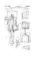
FIG. 5 is a side elevation, partly in section, of a sonic machine for drawing metal in accordance with the invention, the parts being shown at the end of a forming operation;
FIG. 6 is a fragmentary view of a portion of the machine of FIG. 5, but showing the parts in a different (initial) position;
FIG. 7 is a plan View of the metal blank in position ou the die and before engagement by the punch;
FIG. 8 is a fragmentary sectional View of the die and metal blank, the punch being in an intermediate position, with the blank partially formed; and
FIG. 9 shows a modification of the apparatus of FIG. 5.
The invention will be disclosed first in a simple illustrative application to the extrusion of thermoplastic materials, reference being had to FIGS. -l-3 showing simple illustrative extrusion apparatus equipped with means for applying sonic wave action both to the material being extruded and to the extrusion die members. A generally cylindrical material :chamber l2 has an inlet 13 supplied with pressurized heated plastic material m in a iiowable state from a suitable pressure source or pump, not shown, via a conduit 14, and has fastened to one end thereof a vibratory die plate or disc 15 formed with a central oriice 16 through which the material is to be extruded. Chamber 12 is here shown formed with a heat jacket 17 for the purpose of maintaining the material within the chamber 12 in a proper state of plasticity for good extrusion. The end of cylindrical chamber 12 opposite the die plate 15 has an end wall 18 formed, in axial alignment with extrusion orifice 16, with an aperture 19 to receive an elastic bar or mandrel 20, typically of circular crosssection. Mandrel 26, in the present instance, includes a reduce-d extremity 21 projecting with annular clearance through the die orifice 16, the extremity 21, which serves as an inner die member, being connected to the main portion of the mandrel on a streamlined contour as clearly shown in FIG. 1. Mandrel projects through wall 18 by way of a sleeve 22 extending outwardly from wall 13 on a diameter somewhat larger than that of aperture 19, as shown. The annular shoulder 23 formed by this construction is engaged by one side of an annular flange 24 formed about the mid-portion of mandrel 20, and the other side of this flange is engaged by a resilient washer 25, which is in turn backed up by a nut 26 screwed into sleeve 22.
The extremity of mandrel portion 20a, outward of flanger 24, has a mounting fiange 3i), to which is secured a vibration generator generally designated by the numeral 31. The generator 31 may be any one of various types, and may be designed to produce any one of various modes of vibration, such ask longitudinally of the rod, transverse, 'or gyratory, as will be explained in more particular hereinafter.
The contours of the die orice 16 in outer die 15 and of lmandrel portion or inner die 21 are subject to variation in accordance with the desired cross-section of the extrusion to be produced.` In the present illustration, vit is assumed that simple cylindrical tubing is to be extruded, in which case thev orifice 16 is circular in cross-section, as is the mandrel portion 21. It will be understood, of course, that these shapes may be varied as desired, and that, because of the facilitation of the extrusion process by the application of sonic wave acion, cross-sectional shapes impossible to produce with previously known techniques, such for example as thin fins, are well within the capabilities of the present process and apparatus. The die orifice 16 and mandrel portion 21 are longitudinally contoured, in ac-cordance with more or less conventional practice, to provide a streamlined, convergeht entrance throat z leading into the constricted region where the final shaping is imparted to the material. Further, while I have here shown apparatus for extruding a Atubular shape, it will be understood that in any case:
in which a solid shape is to be extruded, the mandrel 20 will be terminated short of the die orifice such as at plane x-y. In such case, the mandrel serves only as a sound wave radiating device, its function as an inner die member having been removed.
While various types of vibration generator might be employed, I prefer to employ an electrically driven mechanical type such as is disclosed and claimed in my application Ser. No. 121,385, tiled Mar. 2'1, 1962, for Vibration Generator for Resonant Loads and Sonic Systems Embodying Same. A generator of this type will be somewhat diagrammatically shown and described herein, and for additional details, reference may be had to said copending application;
As here shown, the vibration generator 31 comprises a housing 35 engaging the mounting flange 30 on the end of elastic mandrel 20, and secured thereto by long machine screws 36. The vhousing 35 embodies a rectangular body 3S formed with a horizontal cylindrical bore 39, and end plates 40 and 41 secured to opposite sides of body 38 over the ends of bore 39. The lbore 39 forms a raceway for a cylindrical orbital inertia rotor, of somewhat smaller diameter, designated generally by numeral 45. The rotor 45 embodies a cylindricalk inertia roller- 46, of somewhat lesser diameter than that of raceway bore 39, as illustrated in FIGS. 2 and 3, for example, and which is rotatably mounted on an axle 47 projecting axially from the hub of a spur gear 48, which alsor comprises a part of rotor 46. The pitch circle of this spur gear 43 is of substantially the same diameter as that of the roller 46. Gear 48 meshes with an internal gear 49 located within housing body 3S concentrically with raceway bore 39, and whose pitch circle is of substantially the same diameter as that of said bore.
The rotor 46 is designed to move in an orbita-l path about its raceway bore 39 las a gui-de, bearing against the surface of said bore by centrifugal for-ce. In this motion, gear 48 runs in mesh with internal gear 49. To maintain the roller in proper engagement with the raceway 39 while the generator is at rest, or coming up to Speed, the axle 47 is provided with an axial pin 52 which rides around and is guided `by a circular boss 53 projecting inwardly from end plate 40 coaxially with raceway Ibore 39.
The rotor 45 is driven through a universal joint coupling 55 connected between a conically gyratory drive shaft 56 and the hub of spur gear 248. vThe rotor 45, comprised of the assembly of roller 46 and gear 48, is laterally guided between the inside surfaces of end plates 40 and 41, having a close working tit therewith.
The opposite end of conically gyratory d-rive shaft 56 is coupled, through universal joint 57, with the drive shaft of an electric drive lmotor 58, and said motor is prefer- ;a-bly of the type incorporating an adjustable Imeans of conventional nature for regulating the speed of its drive shaft. The details of such speed vregulation means need not, of course, be illustrated or described herein in view of their familiarity to those skilled in the art.
Drive motor 58 is mounted at the extremity of a bracket 59 lhere shown as mounted on and-projecting from the extrusion apparatus.
Operation of the vibration generator is .as follows: Rotation of shaft 56 produced by operation of motor 58 causesspur gear 4S to roll around internal gear 49, the `shaft 56 moving in a conical gyratory fashion. The 4inertia roller 46 .rolls on the bearing surface affordedfby -bore 39, so that the rotor 45 moves in an orbital path. The centrifugal force developed by the rotor moving in its orbital path is applied to the body member 38, and hence to the entire generator housing 31, the centrifugal force vector rotating about the axis of -raceway 39. The roller 46 turns at nearly the same rate of rotation as the gear 48,-with any slight variation or creep therebetween accommodated by the .rotatable mounting of the roller on :shaft 47. Thus a gyratory force is exerted on the body 38, and therefore on the housing 35 as a whole, and this gyratory force is exerted against the mounting iiange 30 on the end of the elastic mandrel 20.
It will be lseen that a component of oscillating force is thus delivered to the end of elastic mandrel 20 in a direction laterally of they latter, and that also a component `of oscillatory force is exerted on the end of the lmandrel. 20 in a direction iongitudinally of the mandrel.
The =mandrel 2t) is supported effectively near its midpoint through its mounting iiange 24, and is arranged to undergo free-free` standing wave elastic vibration, and this vibration may be either predominantly in the longitudinal mode, or predominantly inthe transverse mode, depending upon whether the oscillating force delivered by the generator 31 is near a resonant frequency of the mandrel for longitudinal elastic vibration, or is near a resonant frequency of the mandrel vfor transverse elastic vibration. Generally speaking,lparticularly with inner and outer die members, as here shown, for purpose of extruding ra tubular member, it is deemed preferable to choose primarily the longitudinal mode of vibration, and such will be assumed for the purpose of the present illustration, though of course without implied limitation thereto. In such case, motor '58 is regulated to accomplish a spin frequency of inertia rotor 45 which corresponds to a longitudinal resonant vibration frequency of the -mandrel 20. Thus, the mandrel may 'bevibrated in a halfwavelength mode by proper choice of the spin frequency of the yinertia rotor lof the generator, such that the supported ymid-point of the mandrel becomes the location of a node, and the two end portions thereof are the locations `of anti-nodes of the standing wave. Under such circumstances, each half-portion of the mandrel alternately elastically elongates and contracts, the two half-portions of course undergoing4 this action in step with one another. The =side surfaces of the mandrel 2t) have a degree of shear coupling with the surrounding plastic material, and therefore subject the material to sound wave vibration. The slan-ting shoulder 2Gb between the central portion of the Imandrel and the reduced extrem-ity 21 has a longitudinal sonic drive coupling with the material Within the throat region t and constricted d-ie annulus s, and thus applies sonic wave action to the material ilowing to and through the die annulus.
Moreover, not only is the plastic material subjected to 'sound wave action ahead of and within the die annulus but the inner die member 21 also vibrates (in a longitudinal direction) with respect to the plastic material being extruded over 'its outer surface. This sound wave .action increases the fluidity of the material. A dynamic fluidity is produced, owing to the sonic vibration of the material, and to vibratory shear st-resses set up therein. The Isonic vibration so imparted to the material flow-ing through the die annulus, and also the longitudinal vibration Imount-ing of the inner die -member 21, reduce the friction between the extruding material and the inner die member, so that the material tends to flow uniformly, without retardation by reason `of -slid-ing friction with the member 21.
The invention further provides. as `a -preferred but optional feature, a means for imparting sonic elastic vibration to the outer die member or pla-te 15, and to this end, a second sonic vibration generat-or 70, which may be exactly like the sonic Vibration generator 58, may be mounted on the outer die member 15. The sonic generator may ybe mounted near the center of the die, or as in this case, on its upper edge, as shown in FIG. l. Also fragmentarily shown .in FIG. l is the variable speed drive motor 71 for vibration generator 70, and a bracket means 72 mounted on the son-ic extru-sion apparatus and understood to provide support for the drive -motor 71. The details of the generator 7i?, the drive motor 71, and the drive couplingtherebetween, need not be separately shown, since they are identical to those of the generator 31. To indicate in the drawings the orientation of the rotor and raceway bore, however, the rotor for generator 76 is indicated in FIG. 1 at 73, and the raceway bore at 74.
By choice of spin frequencies for the orbital of gyratory rotor 73 of generator 7 0, various of the selective resonant modes of Vibration may be imparted to the member 15. The frequency of the sonic generator-may be chosen to generate a radial dilation mode in die 15. One preferred mode is a flexural plate type mode, characterized by an in-and-out elastic bowing of the die or plate 15. Vibration thus -occurs transverse to the plane of the plate or disk. The outer or rim portion of the plate oscillates elastically at right angles to the plane of the disk, the inner portion of the disk likewise oscillates elastically in a ydirection at right angles to the plane of the disk, but in opposite phase, and an annular nodal region of minimized oscillation occurs between the rim and inner portions of the disk. This vibration pattern is represented by the standing wave diagram st in FIG. 1, where there are nodal regions at N, and antinodes V at the rim of the disk and in the center portion thereof. The plate is proportioned to place the nodal region N in approximate alignment with the wall 12, so that the member 10 is supported at a region of small or zero vibration. The indicated mode of vibration occurs at a certain pre-determined resonance vibration frequency, which can be attained by regulation of speed of the drive motor 71 for the sonic vibration generator.
It will be seen that in this mode of operation, the die surfaces defining the orifice 16 vibrate sonically relative to the ilowof the extrusion, so that retardation of flow along such surfaces is reduced. In result, the material being extruded moves uniformly throughout its crossti section without retardation and consequent rolling action over the surfaces of the die members.
As mentioned earlier, the material being extruded flows with lower pressure, and/or at lower temperatures, Hows uniformly throughout its cross-section, and with such facility that more complex cross-sectional configurations can be employed than were possible heretofore, including thin longitudinal tins and other complex shapes of large surface.
FIG. 4 shows a modification, wherein the vibration generator 80, of the same type as that shown and described in FIGS. 1-3, is so mounted on the end of the elastic mandrel 20 that the orbit of the rotor, indicated at 81 in cylindrical raceway bore 82, is in a plane transverse to the mandrel. In other Words, the longitudinal axis of the raceway bore 82 is either co-incident with or at least parallel to the longitudinal axis of the mandrel 20; In this case, the centrifugal forcefexerted by the rotor 81 acts to gyrate the end'portion of the mandrel 2t). In effect, the end'portion of the mandrel is subjected to a rotating force vector which extends radially through the longitudinal axis of the mandrel.- The effect is to cause the mandrel to tbe progressively elastically bent in a circular path, each point on the end portion of the mandrel describing a small circle. This elastic bending action is propagated as a wave transmitted along the length of the mandrel, reflected back lfrom, the far end thereof, rereflected at the beginning end7 etc. A resonant frequency exists for this mode of vibration in the bar, and when the drive motor 83, coupled to the vibration generator by the conically gyratory shaft 84, is regulated to impart to theV rotor 81 a spin frequency which corresponds with the resonant frequency for a gyratory type standing wave in the mandrel, such wave action is set up in the mandrel. Aswith the longitudinal mode previously described, a
`nodal point exists at the mid-point of the elastically vibrating mandrel, and gyratory antipodes at the two ends thereof. Accordingly, with this mode of vibration, the reduced mandrel portion 21 gyrates in a plane transverse to the klongitudinal axis of the extrusion, applying correspending sonic wave action thereto, resulting in enhanced fluidity, or tiowability, through the, die.
Reference is next directed to FIGS. 5 toS, inclusive, disclosing an application of the invention to drawing or reforming of a ductile metal part from a preform. The drawing apparatus, to be described in detail presently, has many features in common with the extrusion apparatus of FIGS. 1 to 3, as will appear presently.- For illustrative purposes, therehas been shown, as a typical part or preform to be drawn, a flat metal disk (FIG. 6) having a center hole 91 extending therethrough. This disk is to be drawn from the initial shape shown in FIG. 6 through the intermediate shape represented at 90a in FIG. 8 to the final shell ring form 90b illustrated in FIG. 5.
The apparatus of FIGS. 5 to 8 includes a fragmentariiy illustrated base 94 having a horizontal top 95, a head 96 supported vertically above top 95 by means of four rods 97, and a cross head 98 slidable on rods 97. The lower end portions ofthe rods 97 pass through ears 98 formed on base 94 and are fixed tightly to the latter by means of nuts 99 and 100. The upper extremities of the rods 97 pass through bores 101 in head 96 and are fixed to the latter by means of. nuts 162 and 103. Coil compression l springs encircle rods 97 between nuts 99 and the cross head 98, and act, when depressed, as to the position of the cross head shown in FIG. 5, to return the cross head, as well as the later described punch, to the beginning or ele.- vated position shown in FIG. 6.
Cross head98 carries a vertical punch 120. This punch 120, which is Vcomposed of an elastic material such as alloy steel with good elastic fatigue properties, is very much the same as the mandrel 20 of the embodiment of FIG. 1, and can be substantially identical to the latter excepting for modification at its lower extremity to adapt it to the particular drawing operation in hand.
Thus, in the present instance, the punch or mandrel 120 is shown to have a lower reduced active punch element or extremity 121 having a rounded lower end or nose 122, and a concave flaring surface at 123, merging smoothly with a convex surface 124, which in turn merges smoothly with the cylindrical cont-our of the large diameter portion of the punch or mandrel. The punch or mandrel 20v extends through a relatively close fitting vertical bore 126 formed in cross head98, and has near its mid-point an annular flange 127 which seats downwardly on the annular upwardly facing shoulder afforded by a counterbore 128 formed in the cross head. Lodged inside counterbore 128, immediately above ange 127, is
a rubber O-ring 129, and the latter is held in position by means of a gland 130 screwthreaded into the top of the coun-terbore 128.
The upper portion 120a of mandrel 120 passes through an aperture 132 in head 96 and mounts on its upper extremity a vibration generator 134, which may typically be exactly like the vibration generator 31 of FIG. 1, being driven by an electric drive motor 135 corresponding with the drive motor 58 for the generator 31, said motor 135 being mounted on a bracket 136 which .is itself mounted on cross head 98, and projects through the aperture 132 in head 96. It will of course be understood that the vibration generator 134 is driven from electric drive motor 135 by means of a conically gyratory shaft, not
shown, but which will be understood to be like the shaft 56 of FIG. 2. The gyratory inertia rotor of generator 134 is designated generally by the numeral 138.
A die or die plate or wall 140 is mounted on the top 95 of base 94, and, asshown, one side thereof is laterally extendedas at 140:1, and supports a vibration generator 142, corresponding with the generator 70 of FIG. 1. The generator 142 may be of any type capable of suitably vibrating the die 140, but is here indicated as being of the same type as the generators 70 and 31 of FIG. I. Thus, the generator 142 may bedriven by an electric drive motor 143 fragmentarily shown in FIG. 5, and understood to be coupled with generator 142'by a gyratory sh'af-t similar to the shaft 56 of FIG. 2, and to be mounted on a suitable bracket 144 affixed to vbase 94. The die 140, i.e., the outer die, has a die orifice, opening, or recess 148, aligned with and adapted to receive the inner die or punch member 121 of mandrel 120, and this die recess, in the present example, is radiused as at 149, in general correspondence with the curvedportion 123 of the punch. The die is secured to base 94 as by light, elastic bolts 150, so that it is free to vibrate elastically through a very small amplitude relative to the base under the inuencey of the vibratory output of vibration generator 142. Preferably, the vibration frequency of generator 142 is adjusted relative to the size and geometry of die 140 to set up 'a standing wave pattern therein, such as in a liexural mode such as discussed in connection with the die 15 of FIGS. l-,3. Thereby sonic vibrations of small amplitude but relatively high frequency, with a principle component parallel to the die punch, are set up in the die 140, and particularly at the surface defining the die recess 148, so that such vibration will be transmitted to the metal blank as the latter is forced into recess 149.
Operation of the drawing process and apparatus illustrated in FIGS. 5 to 8 is as follows: The die punch 120 lbeing in the beginning position of FIG. 6, the blank 90, in the form of a perforated disk, is placed on die 140over die recess 148, with its aperture' 91 aligned with kthe punch. The blank 90 may be preliminarily positioned by any suitable means, such as by positioning pins 155 set into `die 140. Vibration generator 13S is then driven, so as to set up a longitudinal standing wave in the mandrel 120, thereby causing sonic frequency vibration, in a longitudinal direction, of the punch element 121; or,
The generator 134 is operated to setup in the mandrel 120 elastic standing wave Vvibrations of the same general character described in connection with FIG. `1. As pointed out in the discussion of the operation of the apparatus of FIG. l, either a lateral or a longitudinal mode of standing wave action can be set up in the mandrel, and this is also true-of ythe process` and apparatus of FIGS. 5 to 8, though again, as in the earlier instance, the longitudinal standing wave action is generally preferably, and will be chiefly considered, though without implied limitationthereto. A longitudinal standing Wave being thus set up in the mandrel 20, it will be understood that the punch element or extremity 121-is set into sonic elastic FIG. 5. Such downward movement :may be terminated by any suitable stop means, not shown, after which, through manipulation of suitable control means, the fluid introduced into cylinders is withdrawn, and the cross f head 98 and punch are raised back to the beginning position of FIG. 6.
In the illustrative case here given, the aperture 91 'in disk 90 may be assumed to have initially a slightly smaller diameter than the diameter of thereduced end portion of the punch. Accordingly, the rounded nose of the punch passes partially inside the aperture 91, and then bends and draws the inner portion'of the blank 90 downwardly, the punch forcing its way into the aperture 91, and thus coming into tight engagement with the blank. The punch and blank thus move to and through the intermediate position illustrated in FIG. 8, where the punch portion'121 is entirely inside the aperture in the apertured disk or ring, and the ring is bent and drawn downwardly, generally as indicated. The rin-g is here tightly impaled on the punch. In the position of FIG. 8, the ring has already been stretched downwardly. somewhat, and corresponding tension has been set up therein. Also, in and near the position of FIG. 8, the partially formed ring is already feeling the favorable influences of the vibratory action of the punch and the die 140. The vibrations in the latter are transmitted into the ring, and facilitate the sliding of the molecules of the material of the ring relative to one another as the ring is formed into its new shape. The tensile drawing of the metal of the ring is particularly aided. At the same time, the punch is exerting a vibratory action on and in the ring then impaled thereon, and
greatly increases the vibratory action in the ring in the axial direction, i.e., in the di-rection of the drawing action, and thus aids said action by improving the ability of the molecules of the ring to slide past or relative to one another under the applied tensile stress.
As the punch and ring move on down and to the final position of FIG. 5, the ring moves obviously into greater and greater surface engagement with the defining surfaces of both the punch and the die recess or orifice, and the vibratory action transmitted into the ring is correspondingly increased, and, of course, the benefits of the vibration more fully realized. It will be appreciated that a deep tensile drawing takes place between the positions of FIG. 8 and 1, and the necessary plastic ow of the material of the ring is nicely aided by the sonic vibration at this time.
FIG. 9 `shows a modification of the apparatus of FIGS. 8, designed for the making of a cup or hat-shaped part from a flat disk ductile metal blank by a deep drawing operation using a yieldable rubber or neoprene die. The punch is indicated generally at 160, on the end of fragmentarily illustrated mandrel 161, which will be understood to be similar to mandrel 120 of FIG. 5 and to be similarly operated and vibrated.
The drawings and description will be understood to be of present preferred illustrative embodiments of the invention, and it will be understood that many variations thereof are within the scope of the invention as defined by the broader of the appended claims.
I claim:
1. The process of forming plastic material by forming it between a die and a mandrel comprising:
vibrating at least one of said die and said mandrel at a resonant frequency thereof during the forming process.
2. rI`he method of extruding a plastic material through an orice in a die that comprises:
setting up vibration of said die at a resonant frequency thereof during the extrusion process.
3. The process of reforming a pre-form between a die and a punch comprising:
vibrating at least one of said die and said punch at a resonant frequency thereof during the reforming process.
4. An apparatus for extruding plastic material comprising:
a chamber for holding a pressurized material to be extruded, said chamber having an extrusion die connected thereto; and
mechanical oscillator means connected for vibrating the die at a resonant frequency thereof during said forming.
5. An apparatus for forming plastic material by forming it between a die and a mandrel comprising:
a die member and a mandrel mounted With said material between said die member and said mandrel; and
mechanical oscillator Ameans connected for vibrating at least one of said die and said mandrel at a resonant frequency thereof during said forming.
6. An apparatus for reforming a pre-form between a die and a punch comprising:
a die and a punch mounted for relative movement therebetween with said pre-form between said die and said punch; and
mechanical oscillator means connected for vibrating at least one of said die and said punch at a resonant frequency thereof during said reforming.
References Cited by the Examiner UNITED STATES PATENTS 2,408,627 10/ 1946 Green 264-70 2,549,179 4/1951 Deboutteville 264 2,717,474 9/ 1955 Smith 264 3,002,614 10/1961 Jones 264-70 ROBERT F. WHITE, Primary Examiner.
ALEXANDER H. BRODMERKEL, Examiner.
Claims (1)
1. THE PROCESS OF FORMING PLASTIC MATERIAL BY FORMING IT BETWEEN A DIE AND A MANDREL COMPRISING: VIBRATING AT LEAST ONE OF SAID DIE AND SAID MANDREL AT A RESONANT FREQUENCY THEREOF DURING THE FORMING PROCESS.
Priority Applications (1)
| Application Number | Priority Date | Filing Date | Title |
|---|---|---|---|
| US275157A US3233012A (en) | 1963-04-23 | 1963-04-23 | Method and apparatus for forming plastic materials |
Applications Claiming Priority (1)
| Application Number | Priority Date | Filing Date | Title |
|---|---|---|---|
| US275157A US3233012A (en) | 1963-04-23 | 1963-04-23 | Method and apparatus for forming plastic materials |
Publications (1)
| Publication Number | Publication Date |
|---|---|
| US3233012A true US3233012A (en) | 1966-02-01 |
Family
ID=23051101
Family Applications (1)
| Application Number | Title | Priority Date | Filing Date |
|---|---|---|---|
| US275157A Expired - Lifetime US3233012A (en) | 1963-04-23 | 1963-04-23 | Method and apparatus for forming plastic materials |
Country Status (1)
| Country | Link |
|---|---|
| US (1) | US3233012A (en) |
Cited By (35)
| Publication number | Priority date | Publication date | Assignee | Title |
|---|---|---|---|---|
| US3431988A (en) * | 1966-01-20 | 1969-03-11 | Bodine Albert G | Sonic method and apparatus for inserting fastening elements into plastic compliant bodies |
| US3447480A (en) * | 1967-07-24 | 1969-06-03 | Bodine Albert G | Method and apparatus for gravity flow casting utilizing sonic energization |
| US3447587A (en) * | 1967-07-24 | 1969-06-03 | Bodine Albert G | Method and device for mold casting utilizing sonic energization |
| US3456295A (en) * | 1963-01-16 | 1969-07-22 | Yasuo Torigai | Method and apparatus for improving the coatability in the manufacture of coated welding rod or wire |
| US3643483A (en) * | 1969-08-13 | 1972-02-22 | Univ Ohio State | Sonic system for deformation of sheet material |
| US3657910A (en) * | 1969-09-16 | 1972-04-25 | Nippon Kokan Kk | Method and apparatus for cold drawing metal tubes |
| US3863484A (en) * | 1971-02-25 | 1975-02-04 | Nippon Kokan Kk | Apparatus for drawing wires and tubes |
| US3874207A (en) * | 1957-10-22 | 1975-04-01 | Jerome H Lemelson | Extrusion apparatus |
| US3879974A (en) * | 1973-02-09 | 1975-04-29 | Nat Res Dev | Forming of materials |
| US4017237A (en) * | 1975-03-05 | 1977-04-12 | Bethlehem Steel Corporation | Injection mold with ultra sonic gating means |
| US4028033A (en) * | 1975-04-21 | 1977-06-07 | Branson Ultrasonics Corporation | Apparatus for embossing a plastic workpiece using vibratory energy |
| US4500280A (en) * | 1982-07-13 | 1985-02-19 | Legrand | Vibration-aided feed device for a molding apparatus |
| US4793954A (en) * | 1987-08-17 | 1988-12-27 | The B. F. Goodrich Company | Shear processing thermoplastics in the presence of ultrasonic vibration |
| US4865680A (en) * | 1988-12-23 | 1989-09-12 | Eastman Kodak Company | Ultrasonic securing system |
| EP0370394A2 (en) * | 1988-11-24 | 1990-05-30 | Idemitsu Kosan Company Limited | Apparatus for extrusion |
| EP0465660A1 (en) * | 1990-01-20 | 1992-01-15 | Idemitsu Kosan Company Limited | Method of extrusion molding and apparatus therefor |
| US5112206A (en) * | 1991-05-16 | 1992-05-12 | Shell Oil Company | Apparatus for the resin-impregnation of fibers |
| US5114633A (en) * | 1991-05-16 | 1992-05-19 | Shell Oil Company | Method for the resin-impregnation of fibers |
| US5202066A (en) * | 1989-04-25 | 1993-04-13 | Idemitsu Kosan Co., Ltd. | Method of plasticizing molding material and apparatus therefor |
| US5801106A (en) * | 1996-05-10 | 1998-09-01 | Kimberly-Clark Worldwide, Inc. | Polymeric strands with high surface area or altered surface properties |
| US5803106A (en) * | 1995-12-21 | 1998-09-08 | Kimberly-Clark Worldwide, Inc. | Ultrasonic apparatus and method for increasing the flow rate of a liquid through an orifice |
| US5868153A (en) * | 1995-12-21 | 1999-02-09 | Kimberly-Clark Worldwide, Inc. | Ultrasonic liquid flow control apparatus and method |
| US6020277A (en) * | 1994-06-23 | 2000-02-01 | Kimberly-Clark Corporation | Polymeric strands with enhanced tensile strength, nonwoven webs including such strands, and methods for making same |
| US6036467A (en) * | 1994-06-23 | 2000-03-14 | Kimberly-Clark Worldwide, Inc. | Apparatus for ultrasonically assisted melt extrusion of fibers |
| US6053424A (en) * | 1995-12-21 | 2000-04-25 | Kimberly-Clark Worldwide, Inc. | Apparatus and method for ultrasonically producing a spray of liquid |
| US6380264B1 (en) | 1994-06-23 | 2002-04-30 | Kimberly-Clark Corporation | Apparatus and method for emulsifying a pressurized multi-component liquid |
| US6450417B1 (en) | 1995-12-21 | 2002-09-17 | Kimberly-Clark Worldwide Inc. | Ultrasonic liquid fuel injection apparatus and method |
| US6543700B2 (en) | 2000-12-11 | 2003-04-08 | Kimberly-Clark Worldwide, Inc. | Ultrasonic unitized fuel injector with ceramic valve body |
| US6663027B2 (en) | 2000-12-11 | 2003-12-16 | Kimberly-Clark Worldwide, Inc. | Unitized injector modified for ultrasonically stimulated operation |
| US20060131440A1 (en) * | 2004-12-02 | 2006-06-22 | Hon Hai Precision Industry Co., Ltd. | Method and apparatus for dispersing small particles in a matrix |
| WO2008070636A1 (en) * | 2006-12-01 | 2008-06-12 | Ftf, Llc | Variable-density preforms |
| US20100095724A1 (en) * | 2006-10-13 | 2010-04-22 | Kotagiri Seetarama S | Metal forming with vibration assist |
| US20100159197A1 (en) * | 2007-06-20 | 2010-06-24 | Novative Properties Company | Ultrasonic injection molding on a web |
| US20140072728A1 (en) * | 2012-09-10 | 2014-03-13 | Apple Inc. | Wire and cable extrusion processes |
| DE102016215563A1 (en) * | 2016-08-19 | 2018-02-22 | Leoni Kabel Gmbh | Method for producing a pipe and pipe |
Citations (4)
| Publication number | Priority date | Publication date | Assignee | Title |
|---|---|---|---|---|
| US2408627A (en) * | 1943-10-11 | 1946-10-01 | Lee B Green | Apparatus for extruding |
| US2549179A (en) * | 1941-07-01 | 1951-04-17 | Deboutteville Marcel Delamare | Device for the manufacture of artificial fibers |
| US2717474A (en) * | 1952-11-12 | 1955-09-13 | Pilkington Brothers Ltd | Apparatus for and method of continuously forming a ribbon of glass |
| US3002614A (en) * | 1956-12-13 | 1961-10-03 | Jones James Byron | Vibratory squeeze-forming of metals in the solid state and apparatus therefor |
-
1963
- 1963-04-23 US US275157A patent/US3233012A/en not_active Expired - Lifetime
Patent Citations (4)
| Publication number | Priority date | Publication date | Assignee | Title |
|---|---|---|---|---|
| US2549179A (en) * | 1941-07-01 | 1951-04-17 | Deboutteville Marcel Delamare | Device for the manufacture of artificial fibers |
| US2408627A (en) * | 1943-10-11 | 1946-10-01 | Lee B Green | Apparatus for extruding |
| US2717474A (en) * | 1952-11-12 | 1955-09-13 | Pilkington Brothers Ltd | Apparatus for and method of continuously forming a ribbon of glass |
| US3002614A (en) * | 1956-12-13 | 1961-10-03 | Jones James Byron | Vibratory squeeze-forming of metals in the solid state and apparatus therefor |
Cited By (49)
| Publication number | Priority date | Publication date | Assignee | Title |
|---|---|---|---|---|
| US3874207A (en) * | 1957-10-22 | 1975-04-01 | Jerome H Lemelson | Extrusion apparatus |
| US3456295A (en) * | 1963-01-16 | 1969-07-22 | Yasuo Torigai | Method and apparatus for improving the coatability in the manufacture of coated welding rod or wire |
| US3431988A (en) * | 1966-01-20 | 1969-03-11 | Bodine Albert G | Sonic method and apparatus for inserting fastening elements into plastic compliant bodies |
| US3447480A (en) * | 1967-07-24 | 1969-06-03 | Bodine Albert G | Method and apparatus for gravity flow casting utilizing sonic energization |
| US3447587A (en) * | 1967-07-24 | 1969-06-03 | Bodine Albert G | Method and device for mold casting utilizing sonic energization |
| US3643483A (en) * | 1969-08-13 | 1972-02-22 | Univ Ohio State | Sonic system for deformation of sheet material |
| US3657910A (en) * | 1969-09-16 | 1972-04-25 | Nippon Kokan Kk | Method and apparatus for cold drawing metal tubes |
| US3863484A (en) * | 1971-02-25 | 1975-02-04 | Nippon Kokan Kk | Apparatus for drawing wires and tubes |
| US3879974A (en) * | 1973-02-09 | 1975-04-29 | Nat Res Dev | Forming of materials |
| US4017237A (en) * | 1975-03-05 | 1977-04-12 | Bethlehem Steel Corporation | Injection mold with ultra sonic gating means |
| US4028033A (en) * | 1975-04-21 | 1977-06-07 | Branson Ultrasonics Corporation | Apparatus for embossing a plastic workpiece using vibratory energy |
| US4500280A (en) * | 1982-07-13 | 1985-02-19 | Legrand | Vibration-aided feed device for a molding apparatus |
| US4793954A (en) * | 1987-08-17 | 1988-12-27 | The B. F. Goodrich Company | Shear processing thermoplastics in the presence of ultrasonic vibration |
| EP0370394A2 (en) * | 1988-11-24 | 1990-05-30 | Idemitsu Kosan Company Limited | Apparatus for extrusion |
| EP0370394A3 (en) * | 1988-11-24 | 1991-07-03 | Idemitsu Kosan Company Limited | Apparatus for extrusion |
| US5068068A (en) * | 1988-11-24 | 1991-11-26 | Idemitsu Kosan Co., Ltd. | Method and apparatus for extrusion |
| US4865680A (en) * | 1988-12-23 | 1989-09-12 | Eastman Kodak Company | Ultrasonic securing system |
| US5202066A (en) * | 1989-04-25 | 1993-04-13 | Idemitsu Kosan Co., Ltd. | Method of plasticizing molding material and apparatus therefor |
| EP0465660A4 (en) * | 1990-01-20 | 1993-01-07 | Idemitsu Kosan Company Limited | Method of extrusion molding and apparatus therefor |
| EP0465660A1 (en) * | 1990-01-20 | 1992-01-15 | Idemitsu Kosan Company Limited | Method of extrusion molding and apparatus therefor |
| US5114633A (en) * | 1991-05-16 | 1992-05-19 | Shell Oil Company | Method for the resin-impregnation of fibers |
| US5112206A (en) * | 1991-05-16 | 1992-05-12 | Shell Oil Company | Apparatus for the resin-impregnation of fibers |
| US6395216B1 (en) | 1994-06-23 | 2002-05-28 | Kimberly-Clark Worldwide, Inc. | Method and apparatus for ultrasonically assisted melt extrusion of fibers |
| US6380264B1 (en) | 1994-06-23 | 2002-04-30 | Kimberly-Clark Corporation | Apparatus and method for emulsifying a pressurized multi-component liquid |
| US6036467A (en) * | 1994-06-23 | 2000-03-14 | Kimberly-Clark Worldwide, Inc. | Apparatus for ultrasonically assisted melt extrusion of fibers |
| US6020277A (en) * | 1994-06-23 | 2000-02-01 | Kimberly-Clark Corporation | Polymeric strands with enhanced tensile strength, nonwoven webs including such strands, and methods for making same |
| US5868153A (en) * | 1995-12-21 | 1999-02-09 | Kimberly-Clark Worldwide, Inc. | Ultrasonic liquid flow control apparatus and method |
| US6053424A (en) * | 1995-12-21 | 2000-04-25 | Kimberly-Clark Worldwide, Inc. | Apparatus and method for ultrasonically producing a spray of liquid |
| US6315215B1 (en) | 1995-12-21 | 2001-11-13 | Kimberly-Clark Worldwide, Inc. | Apparatus and method for ultrasonically self-cleaning an orifice |
| US5803106A (en) * | 1995-12-21 | 1998-09-08 | Kimberly-Clark Worldwide, Inc. | Ultrasonic apparatus and method for increasing the flow rate of a liquid through an orifice |
| US6450417B1 (en) | 1995-12-21 | 2002-09-17 | Kimberly-Clark Worldwide Inc. | Ultrasonic liquid fuel injection apparatus and method |
| US6659365B2 (en) | 1995-12-21 | 2003-12-09 | Kimberly-Clark Worldwide, Inc. | Ultrasonic liquid fuel injection apparatus and method |
| US5801106A (en) * | 1996-05-10 | 1998-09-01 | Kimberly-Clark Worldwide, Inc. | Polymeric strands with high surface area or altered surface properties |
| US6543700B2 (en) | 2000-12-11 | 2003-04-08 | Kimberly-Clark Worldwide, Inc. | Ultrasonic unitized fuel injector with ceramic valve body |
| US6663027B2 (en) | 2000-12-11 | 2003-12-16 | Kimberly-Clark Worldwide, Inc. | Unitized injector modified for ultrasonically stimulated operation |
| US20040016831A1 (en) * | 2000-12-11 | 2004-01-29 | Jameson Lee Kirby | Method of retrofitting an unitized injector for ultrasonically stimulated operation |
| US6880770B2 (en) | 2000-12-11 | 2005-04-19 | Kimberly-Clark Worldwide, Inc. | Method of retrofitting an unitized injector for ultrasonically stimulated operation |
| US20060131440A1 (en) * | 2004-12-02 | 2006-06-22 | Hon Hai Precision Industry Co., Ltd. | Method and apparatus for dispersing small particles in a matrix |
| US20100095724A1 (en) * | 2006-10-13 | 2010-04-22 | Kotagiri Seetarama S | Metal forming with vibration assist |
| WO2008070636A1 (en) * | 2006-12-01 | 2008-06-12 | Ftf, Llc | Variable-density preforms |
| US20100001231A1 (en) * | 2006-12-01 | 2010-01-07 | Ftf, Llc | Variable-density preforms |
| US8075827B2 (en) * | 2006-12-01 | 2011-12-13 | Ftf, Llc | Variable-density preforms |
| US20120227624A1 (en) * | 2006-12-01 | 2012-09-13 | Ftf, Llc | Variable-Density Preforms |
| US20100159197A1 (en) * | 2007-06-20 | 2010-06-24 | Novative Properties Company | Ultrasonic injection molding on a web |
| US8236231B2 (en) | 2007-06-20 | 2012-08-07 | 3M Innovative Properties Company | Ultrasonic injection molding on a web |
| US8449807B2 (en) | 2007-06-20 | 2013-05-28 | 3M Innovative Properties Company | Ultrasonic injection molding on both sides of a web |
| US8637136B2 (en) | 2007-06-20 | 2014-01-28 | 3M Innovative Properties Company | Articles injection molded on a web |
| US20140072728A1 (en) * | 2012-09-10 | 2014-03-13 | Apple Inc. | Wire and cable extrusion processes |
| DE102016215563A1 (en) * | 2016-08-19 | 2018-02-22 | Leoni Kabel Gmbh | Method for producing a pipe and pipe |
Similar Documents
| Publication | Publication Date | Title |
|---|---|---|
| US3233012A (en) | Method and apparatus for forming plastic materials | |
| CN206614795U (en) | A kind of 3D printer | |
| US2408627A (en) | Apparatus for extruding | |
| US3556888A (en) | Pultrusion machine and method | |
| JP2556647B2 (en) | Parison manufacturing equipment for blow molding bellows | |
| US3684622A (en) | Pultrusion machine | |
| US4786242A (en) | Apparatus for the casting of hollow slabs out of concrete | |
| EP0421019B1 (en) | Method and device for joining plastic parts with ultrasonic waves | |
| EP0197456B1 (en) | A process and apparatus to move and form underground passages in soil | |
| US4555225A (en) | Apparatus for making a twin-wall, internally corrugated plastic structural part with a smooth non-cellular skin | |
| US5360329A (en) | Molding/extrusion apparatus with temperature and flow control | |
| US3288898A (en) | Process of blow molding hollow articles | |
| US3494990A (en) | Method for producing molded bodies of rotation by rolling | |
| US4326903A (en) | Method for securing parts together by ultrasonic energy | |
| DE1963546A1 (en) | Method and device for friction welding | |
| KR20020092253A (en) | Hollow Article Made Of Thermoplastic Resin, Manufacturing Method Of The Hollow Article, And Manufacturing Apparatus Of The Hollow Article | |
| US3169589A (en) | Sonic method and apparatus for extruding flowable materials | |
| US3774890A (en) | Apparatus for working moldable material | |
| DE2628203A1 (en) | PROCESS FOR ULTRASONIC WELDING OF TWO THERMOPLASTIC WORKPIECES | |
| US3972758A (en) | Method of forming over a plastic jacket against a workpiece using vibratory | |
| US5264163A (en) | Method of controlling the internal structure of matter | |
| JP3452925B2 (en) | Improvement of continuous extrusion method and equipment | |
| US4951493A (en) | Method and apparatus for making a spiral pipe | |
| US2801441A (en) | Mechanism for producing internally threaded tubing | |
| US2260750A (en) | Method of and machine for making hollow articles from plastics |