US3228564A - Dispensing device - Google Patents
Dispensing device Download PDFInfo
- Publication number
- US3228564A US3228564A US329722A US32972263A US3228564A US 3228564 A US3228564 A US 3228564A US 329722 A US329722 A US 329722A US 32972263 A US32972263 A US 32972263A US 3228564 A US3228564 A US 3228564A
- Authority
- US
- United States
- Prior art keywords
- housing
- hand grip
- pump housing
- grip member
- elongate
- Prior art date
- Legal status (The legal status is an assumption and is not a legal conclusion. Google has not performed a legal analysis and makes no representation as to the accuracy of the status listed.)
- Expired - Lifetime
Links
Images
Classifications
-
- F—MECHANICAL ENGINEERING; LIGHTING; HEATING; WEAPONS; BLASTING
- F16—ENGINEERING ELEMENTS AND UNITS; GENERAL MEASURES FOR PRODUCING AND MAINTAINING EFFECTIVE FUNCTIONING OF MACHINES OR INSTALLATIONS; THERMAL INSULATION IN GENERAL
- F16N—LUBRICATING
- F16N3/00—Devices for supplying lubricant by manual action
- F16N3/02—Devices for supplying lubricant by manual action delivering oil
- F16N3/04—Oil cans; Oil syringes
- F16N3/08—Oil cans; Oil syringes incorporating a piston-pump
Description
Jan. 11, 1966 J. L. OhSON DISPENSING DEVICE Filed Dec. 11, 1963 INVENTOR. Jbfizvli. Ozswv ATTOE/VFV? inhuman United States Patent 3,228,564 DISPENSING DEVICE John L. Ulson, North Branch, Minn. Filed Dec. 11, 1963, Ser. No. 329,722 9 (Ilaims. (Cl. ZZZ-82) This invention relates to a dispensing device and more particularly to a dispensing device for dispensing liquid from a can.
An object of this invention is to provide a hand type dispensing device having means for piercing an attachment to a sealed can of liquid, such as oil, and having pump means to pump the liquid from the can, and also having a handle structure spaced above the can of liquid to facilitate handling of the can and to permit easy application and removal of the device with respect to such a can of liquid.
Another object of this invention is to provide a dispensing device of the class described and having an actuating lever positioned below and in close proximity to the handle to permit an operator to easily carry and operate the dispensing device with one hand.
A further object of this invention is to provide a dispensing device including pump means arranged and constructed for piercing the can of liquid, and a U-shaped handle structure having attachment elements adapted to frictionally engage the bead of the can of liquid with snap coupling effect to permit the dispensing device to be readily applied to and removed from such a can.
These and other objects and advantages of the invention will more fully appear from the following description made in connection with the accompanying drawing wherein like character references refer to the same or similar parts throughout the several views, and in which:
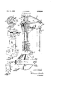
FIG. 1 is a side view of the dispensing device applied to a conventional oil can with certain parts broken away for clarity;
FIG. 2 is a top plan view thereof;
FIG. 3 is a cross sectional view on an enlarged scale taken approximately along line 33 of FIG. 1 and looking in the direction of the arrows;
FIG. 4 is a fragmentary plan view of a portion of the dispensing device on an enlarged scale as viewed from approximately along line 4-4 of FIG. 1 and looking in the direction of the arrows;
PEG. 5 is :an elevational view on an enlarged scale taken approximately along line 55 of FIG. 2 and looking in the direction of the arrows; and
PEG. 6 is an enlarged fragmentary side view on an enlarged scale of the pump housing.
Referring now to the drawings and more specifically to FIG. 1, it will be seen that one embodiment of my novel dispensing device, designated generally by the reference numeral 16, is there shown. The dispensing device 10 includes a pump mechanism 11 which, as seen, is comprised of an elongate, generally cylindrically shaped housing 12 constructed of a suitable rigid metallic material. It will be seen that the lower end portion of the housing 12 is reduced as at 13 and is provided with a plurality of pointed piercing elements 14, as best seen in FIGS. 1 and 6.
When the dispensing device 14 is applied to a can of liquid, such as oil, the pump housing 12 is vertically oriented with the reduced end 13 disposed adjacent the lower inner surface of the can to which it is applied. It will be seen that the upper portion 15 is of enlarged cross sectional shape, this enlarged portion extending exteriorly of the pierced can. This enlarged upper end of the pump housing 12 is provided with a longitudinally or axially extending slot 16 therein as best seen in FIG. 1.
The interior of the housing 12 defines a pump chamber 17 and pump means are positioned in the pump chamber 17 for use in receiving the liquid from the can of elevational liquid and thereafter dispensing the liquid to the exterior. This pump means includes a lower check valve mechanism 18 comprised of a check valve housing 19 which, as seen, has a reduced lower end and corresponding generally in shape to the lower end portion of the pump housing 12. Thus the cooperating shoulders defined by the reduced end of the pump housing 12 and check valve housing 19 serve to retain the check valve mechanism within the pump chamber 17. It will be noted, however, that the check valve mechanism 18 normally projects axially exteriorly of the pump housing 12 as best seen in FIG. 1.
The check valve housing 1? has an axial intake opening 28 in the lower end thereof and an outlet opening 21 in the upper axial end thereof. A check ball valve element 22 is positioned within the check valve mechanism housing 19 and this ball valve element 22 is normally urged into closing relation with respect to the inlet opening by a small helical spring 23.
Another check valve mechanism 24 is provided and is comprised of a check valve housing 25 having an inlet opening 26 in the lower end thereof and having an outlet opening 26a in the upper end thereof. A check ball valve element 27 is normally urged into closing relation with respect to the inlet opening 26 by a small helical spring 23 and it will be seen that this check valve mechanism 24 is connected to the lower end of a piston rod 29. Actually the check valve mechanism 24- constitutes a piston while the lower check valve mechanism 18 permits fluid to be introduced into the pump chamber 17 during axial movement of the upper check valve element 24 in an upward direction. A relatively large helical spring 30 is positioned around the piston rod 29 and has its lower end positioned against the check valve housing 25 and has its upper end bearing against an annular sealing member 31, the latter being formed of a suitable compressible material such as rubber or the like. This sealing member 31 permits axial movement of the piston rod 29 but prevents the escape of fluid from the pump housing 12.
The dispensing device 10 also includes a handle structure 32 also formed of a suitable rigid material such as metal and comprised of a hand grip portion 33 of elongate configuration and normally horizontally disposed when the dispensing device 10 is applied to a can. One end of the hand grip portion 33 has a depending leg 34 integrally formed therewith while the other end thereof has a depending leg 35 integrally formed therewith. It will be noted that the leg 34 is somewhat longer than the leg 35 and that the hand grip portion 33 slants downwardly slightly from the leg 34 towards the leg 35.
The leg 34 has an inturned embossed or annular element 3'5 integrally formed therewith, this annular element 36 being internally threaded as best seen in FIG. 1. The enlarged upper end portion 15 of the pump housing 12 has an opening in one Wall thereof, this opening being disposed in substantially coaxial relation with the annular element 36. With this arrangement, the threaded coupling 57 which is shiftably mounted on one end portion of a discharge spout 38 may be threaded into the annular element 36 so that one end of this discharge nozzle projects interiorly of and in communicating relation with respect to the pump housing 12. It will be seen that the end of the discharge nozzle which projects interiorly of the pump housing 12 has an annular sealing element in the form of an O-ring 39 positioned exteriorly thereof and being mounted and retained in concentric relation with respect to the inner end of the discharge nozzle 38 by an annular retaining element 40 of generally U-shaped cross sectional configuration. It will be seen that when the threaded coupling 37 threadedly engages the annular threaded element 35, the retaining element 40 and the sealing element 39 will be urged axially along the nozzle 38 and into engaging relation against that portion of the pump housing 12 which circumscribes the opening therein. It is pointed out that the sealing element 39 is preferably constructed of a suitable compressible material such as rubber, plastic or the like.
The leg 34 has a pair of laterally spaced-apart snap coupling elements 41 integrally formed with the lower end thereof, the function of which will be more fully described hereinbelow. The leg 35 has a pair of recesses 42 formed in the edges thereof, these recesses actually defining snap coupling elements 43 which, as noted, are disposed substantially oppositely of the snap coupling elements 41. The lower end portion 44 of the leg 35 has the edges thereof converging towards each other and this lower end portion actually flares outwardly to facilitate frictional engagement of the snap coupling elements 43 with the head of the can to which the dispensing device is applied. It will be seen that when the dispensing device 10 is actually applied to a can of liquid, the snap coupling elements 41 and 43 engage the bead of the can at one end thereof with frictional engagement to firmly but releasably secure the dispensing device to the can.
Means are provided in order to permit slight adjustment of the snap coupling elements carried by the legs 34 and 35. To this end, the leg 34 has an adjustment member 45 integrally formed therewith and projecting therefrom towards the leg 35. This adjustment member 45, which has an aperture 46 therein to receive the pump housing 12 therethrough, is of substantially elongate, fiat configuration and extends from the leg 34 a distance corresponding approximately to half the length of the hand grip portion 33 of the handle structure 32. It will be seen that the adjustment member 45 has a pair of slots 47 therein and also has a larger opening 48 therein, as best seen in FIG. 4. That portion of the adjustment member 45 located between the slots 4-7 are struck upwardly as at 49 while the portions located on opposite sides of the upwardly struck portion 49 are, offset or struck downwardly as at 50. The lower surface of the upwardly struck portion 49 and the respective upper surfaces of the downwardly struck portions 50 are threaded to receive the threaded end of an elongate adjustment member or bolt 51 which extends through an aperture in the leg 35. Thus it will be seen that by adjusting the bolt 51 relative to the adjustment member, 45, the snap coupling elements 41 and 43 may be accordingly 'adjusted. 7
It will be seen that the upper end portion of the pump housing 12 is provided with tabs 52 which project through tab receiving slots in the hand grip portion 33 of the handle structure adjacent the leg 34. Since the pump housing 12 also extends through the adjustment member 45 in snug fitting relation therewith, the pump housing is very firmly secured to the handle structure 32. Referring now to FIG. 3, it will be seen that a cylindrical spacer member 53 is disposed in concentric relation within the upper portion of the pump housing 15. This cylindrically shaped spacer member 53 isprovided with a slot 54 therein extending throughout the length thereof, the slot 54 being disposed in substantially registering relation with respect to the slot 16 in the pump housing 12; It will be noted that the cylindrically shaped spacer member 53 engages the under surface of the hand grip portion33 and is also disposed in bearing engagement with the annular sealing member 31 so that the annular sealing member is retained in place by the cooperativeeffects of the spacer member 53 and the large helical spring 30.
The pumpmechanism is also provided with an elongate actuating .lever- 55 preferably constructed of a suitable rigid metallic material and having one end thereof slotted as at 56 to receive the upper end of the piston rod 29 therethrough. It will be noted that the lever 55 is of substantially channel shaped configuration and a retaining 4 element 57 engages the upper end of the piston rod 29 to secure the lever 55 to the piston rod. With this particu lar arrangement, the lever 55 can pivot relative to the piston rod 29.
The other end of the lever has a slot 58 formed therein while the hand grip portion 33 of the handle structure 32 has a generally T-shaped attachment element 59 struck downwardly therefrom and which is inserted through the slot 58. It will be seen from FIG. 5 that the slot or opening 58 in the actuating lever 55 is smaller than the T-shaped retaining element so that the lever is positively connected to the handle structure 33'. This particular connection, however, permits pivoting of the lever 55 in a vertical direction abouta substantially horizontal transverse axis. It will also be noted that the actuating lever 55 is positioned below the hand grip portion 33 and in close proximal vertical alignment therewith. Thus a user may carry the dispensing device 10, when applied to 'a can,
' and also actuate the lever 55 with one hand.
' When the dispensing device 10 is used,ia conventional cylindrically shaped can C containing a liquid such as oil willhavel one of its ends pierced by forcing the pump housing 12 against the top of the can adjacent one side thereof. The piercing elements 14 will readily pierce the can and allow the pump housing to be inserted into the interior of such a can. Although the lower check valve mechanism 18 projects exteriorly through the pump housing, this check valve mechanism 18 may be retracted upwardly during this piercing action against the bias of the large helical spring 30. In order to permit retraction of the lower check valve mechanism 18 and return thereof while also interrelating the check mechanisms 18 and 24 in a manner to permit effective pumping action, an annulus 60 is provided which is interposed between the respective check valve mechanisms 18 and 24. The outer circumferential surface of the annulus or sleeve 60 engages the inner surface of the pump housing with frictional contact so that the annulus can only be moved axially of the pump housing when a force is applied thereto. Therefore during the piercing action by the pump housing, the lower check valve mechanism 18 which will be moved axially upwardly of the pump housing will also caused upward axial movement of the annulus 60 and the check valve mechanism 18 against the bias of the spring 30. However, upon completion of the piercing action, the spring 30 will force the friction sleeve or annulus 60 downwardly into the position illustrated in FIG. 1. During the pumping action, when the check valve mechanism 18 is lifted by Q. means of the piston rod 29, the annulus 60 will engage the inner surface of the pump housing with sufficient friction effect. so as to resist the upward force exerted by the incoming liquid. It will therefore be seen that the annulus 60 yieldably retains the check valve mechanism 24 in its lowermost position but allows retraction of the check valve mechanism 24 during the piercing action, but prevents upward movement thereof during the normal pumping operation. Thus during the piercing action by the pump housing. Thus during the piercing action by the pump housing will be moved axially upwardly of the pump housing. 1
The pump housing will be inserted until the adujstment member 45 engages the upper surface of the can at which time the snap coupling elements 41 and 43 will engage the bead of the can with frictional effect.
When oil or liquid is to be dispensed from the can, the actuating lever 55 is moved upwardly against the bias of the large helical spring 30 which action also moves the check valve mechanism 24 or piston also upwardly. A negative pressureis produced and the small valve element 22 will be unseated thus permitting the fluid to flow into the pump housing. During downward movement of the piston or check valve mechanism 24, the ball valve element 22 will be seated and will prevent the fluid within the pump housing to flow downwardly through the inlet opening 20. Thus by lifting the lever 55 and quickly releasing the same, the fluid may be readily discharged through the discharge nozzle 38.
It will be seen that when the pump housing 12 is inserted into the end of a can of liquid, the use of a plurality of piercing elements, three in the embodiment illustrated, permits a substantially circular hole to be formed in the end of a can. It is also pointed out that since the pump housing 12 is of a length so that at least a part of the enlarged upper portion thereof will be inserted into the opening formed at the pierced end, this enlarged opening will engage the periphery of the hole thus formed with sealing effect. The snap coupling elements 41 are laterally spaced-apart from each other and are generally diametrically opposed to the snap coupling elements 43. With this arrangement, the spacing between the snap coupling elements 41 and 43 may be slightly adjusted when it is desirable without producing elongations of a hole formed in the can.
From the foregoing it will be seen that I have provided a novel dispensing attachment including a pump housing having pump means therein secured to a handle structure, the latter being of generally U-shaped configuration and substantially overlying, in vertically spaced diametrically extending relation, the pierced end of the can to which the dispensing device is applied, whereby the user may very easily carry the can of liquid and actuate the dispensing device with one hand.
It will also be seen from the foregoing description that the handle structure may be readily applied by snapcoupling effect to frictionally engage the bead of the can, thus permitting ready attachment or removal of the dispensing device with respect to such a can.
Thus it will be seen that I have provided a novel dispensing device which is not only of simple and inexpensive construction but one which functions in a more efficient manner than any heretofore known comparable devices.
It will, of course, be understood that various changes may be made in the form, details, arrangement and proportions of the various parts departing from the scope of my invention.
What is claimed is:
1. A dispensing device for use with a can of liquid of the type having a bead at one end thereof, said device comprising an elongate tubular pump housing having a plurality of pointed piercing elements at one end thereof to permit piercing of the end of a sealed can of liquid and insertion of the tubular housing into the can, said housing being oriented axially of the can with the other end of the housing projecting exteriorly of the pierced end of the can,
a dispensing nozzle member connected in communicating relation with said other portion of the tubular housing,
pump mechanism within said housing and being operable for removing liquid from the can,
a handle structure connected to said pump housing and including an elongate hand grip member spaced above the pierced end of the can in substantially diametrically extending relation therewith,
a pair of leg members fixedly connected with the ends of said hand grip member and depending therefrom,
attachment elements carried by the lower ends of said legs and engaging the head of the can at the pierced end thereof with snap coupling effect,
and an elongate actuating lever having one end pivotally connected with said handle structure and having the other end thereof pivotally connected with said pumpmechanism, said actuating lever being positioned below said hand grip member in close proximity thereto and being disposed in substantially vertical alignment with said hand grip member whereby a user may grip the hand grip member and pivot the actuating lever with one hand.
2. A dispensing device for use with a can of liquid of the type having a head at one end thereof, said device comprising an elongate cylindrically shaped pump housing having a plurality of piercing elements at one end portion thereof to permit piercing of a can of liquid and insertion of the housing into said can, said housing being normally oriented vertically and axially of the can with said other end portion of the housing projecting exteriorly of the can,
a dispensing nozzle member detachably connected in communicating relation with said other end portion of the pump housing,
pump mechanism within said housing and being operable for removing liquid from the can,
a handle structure connected with said pump housing and including an elongate hand grip member spaced above the pierced end of the can in substantially diametrically extending relation therewith, said other end portion of the pump housing being connected to said hand grip member and being slotted to define a vertically extending guide,
a pair of leg members fixedly connected with the ends of said hand grip member and depending therefrom,
attachment elements carried by the lower ends of said legs and engaging the bead of the can at the pierced end thereof with snap coupling eifect,
and an elongate actuating lever having one end pivotally connected with said handle structure and having the other end thereof pivotally connected with said pump mechanism and extending into said guide for longitudinal movement relative thereto, said actuating lever being positioned below said hand grip memher in close proximity thereto and being disposed in substantially vertical alignment with said hand grip member and spaced above the pierced end of the can whereby a user may grip the hand grip member and pivot the actuating lever with one hand.
3. The device as defined in claim 2 and an elongate longitudinally adjustable structure interconnecting said leg members and being variously adjustable to adjust the spacing between the leg members and the attachment elements carried thereby.
4-. The device as defined in claim 3 wherein said adjustable structure is also connected with said pump housing.
5. A dispensing device for use with a can of liquid of the type having a head at one end thereof, said device comprising an elongate cylindrically shaped pump housing having a plurality of piercing elements projecting axially from one end portion thereof to permit piercing of the end of a sealed can of liquid and insertion of the tubular housing into the can, said housing being oriented axially of the can and being normally substantially vertically oriented with the other end por-- tion of the housing projecting exteriorly of the pierced end of the can,
a dispensing nozzle member connected in communicating relation with said other end portion of the housing,
pump means within said housing and being shiftable relative thereto, said pump means comprising an axially shiftable, elongate piston rod,
resilient means normally urging said piston rod towards the inserted end of the housing,
a pair of check valve mechanisms positioned Within said pump housing for axial shifting movement relative thereto, one of the check valve mechanisms being connected to one end of the piston rod and defining a piston, the other of said valve mechanisms being normally urged exteriorly of the pump housing, and an annulus interposed between and axially separating said check valve mechanisms,
a handle structure connected to said pump housing and including an elongate hand grip member spaced above the pierced end of the can in substantially diametrically extending relation therewith,
a pair of leg members fixedly connected with theend of said hand 'grip member and depending therefrom,
attachment elements carried by the lower ends of said of the type having a bead at one end thereof, said device comprising an elongate tubular pump housing having a plurality of pointed piercing elements at one end thereof to permit piercing of the end of a sealed can of liquid and insertion of the tubular housing into said can,
said housing being oriented axially of the can with the other end of the housing projecting exteriorly of the'pierced'end of the can, said housing having a radial opening in the exteriorly projecting portion thereof communicating with the interior of said houspump mechanism within said housing,
a handle structure connected to said pump housing and including an elongate hand grip .member spaced above the pierced end of the can in substantially diametrically extending relation therewith,
a pair of leg members fixedly connected with the ends of said hand grip member and dependingth-erefrom, one of said leg members having a threaded aperture therein,
attachment elements carried by the lower end of said legs and engaging the head of the can at the pierced. end thereof with snap coupling efiect,
an elongate actuating lever having one end pivotally connected with saidvhandle structureand having the other end thereof pivotally connected with said pump mechanism, said actuating lever being positionedbelow said hand grip member in close proximity thereto and being disposed in substantially vertical alignment with said hand grip member whereby a user may grip the hand grip member and pivot the actuating lever with one hand,
an elongate substantially rigid dispensing nozzle having an outturned annular element at one end therer a resilient compressible annular sealing element interposed between said outturned annular element and housing and encircling said radial opening in the latter,
' and a threaded coupling member slidably mounted on said nozzle and threadedly engaging the. threaded recess in said one leg to releasably interconnect and intercommunicate said nozzle and said housing.
7. The dispensing'device as defined in claim 6 wherein the end portion of the housing which projects through the pierced end of the can has a cross sectional size slightly greater than the major portion of the housing which is inserted into the can.
8. A dispensing device for use with a can of liquid 9. The dispensing device as defined in claim 8 and an of the type having a head at one end thereof, said device comprising an elongate cylindrically shaped pump housing having a plurality of piercing elements at one end thereof to permit piercing of a can of liquid and insertion of the housing into the can, said housing being normally oriented vertically and axially of the can with 'said other-end portion of the housing projecting exteriorly of the can,
a dispensing nozzle'member detachably connected in communicating relation with said other end portion of the pump'housing,
pump means within said housing and being operable for removing liquid from the can, said pump means comprising an elongate piston rod axially movable in said pump housing, a check valve type piston secured to one end'ofsaid piston rod and movable therewith, yieldableresilient means forrnormally urging said piston-and piston rod in an axial downward direction with respect to said pump housing,
a check valve mechanism positioned within said pump housing adjacent the lower end thereof and being movable relative thereto,' said check valve mechanism comprising a check valve housing having an opening therein, a spring urged ball check valve for normally closing the opening in said check'valve housing and positioned within the latter, said check valve housing being normally urged downwardly with respect to said pump housing and projecting exteriorly of the lower end of the latter,
a handle structure connected with said pump housing and including an elongate hand grip member spaced above the pierced end of the can in substantially diametrically extending relation therewith,
I a pair'of leg members fixedly connected with the ends of said hand grip member and depending therefrom,
' attachment elements carried by the lower ends of said legsand engaging the bead ofthe can at the pierced end thereof with snap coupling efiect, and an elongate actuating lever having one end thereof connected with said handle structure and having the other end thereof connected with said piston rod for moving the latter, said actuating lever being positioned below said hand grip member in close proximity thereto and being disposed in substantially vertical alignment with said hand grip member and spaced above the piercediend of the can whereby a user may grip the hand grip member and pivot the actuating lever with one hand.
elongate extensible and retractable structure interconnecting said leg'members and being positioned below said actuating lever, said adjustable structure being variously adjustable toadjust the spacing between the legmembers and the attachment elements carried thereby.
References Cited by the Examiner UNITED STATES PATENTS RAPHAEL M. LUPO, Primary Examiner. LOUIS J. DEMBO, Examiner.
Claims (1)
1. A DISPENSING DEVICE FOR USE WITH A CAN OF LIQUID OF THE TYPE HAVING A BEAD AT ONE END THEREOF, SAID DEVICE COMPRISING AN ELONGATE TUBULAR PUMP HOUSING HAVING A PLURALITY OF POINTED PIERCING ELEMENTS AT ONE END THEREOF TO PERMIT PIERCING OF THE END OF A SEALED CAN OF LIQUID AND INSERTION OF THE TUBULAR HOUSING INTO THE CAN, SAID HOUSING BEING ORIENTED AXIALLY OF THE CAN WITH THE OTHER END OF THE HOUSING PROJECTING EXTERIORLY OF THE PIERCED END OF THE CAN, A DISPENSING NOZZLE MEMBER CONNECTED IN COMMUNICATING RELATION WITH SAID OTHER PORTION OF THE TUBULAR HOUSING, PUMP MECHANISM WITHIN SAID HOUSING AND BEING OPERABLE FOR REMOVING LIQUID FROM THE CAN, A HANDLE STRUCTURE CONNECTED TO SAID PUMP HOUSING AND INCLUDING AN ELONGATE HAND GRIP MEMBER SPACED ABOVE THE PIERCED END OF THE CAN IN SUBSTANTIALLY DIAMETRICALLY EXTENDING RELATION THEREWITH, A PAIR OF LEG MEMBERS FIXEDLY CONNECTED WITH THE ENDS OF SAID HAND GRIP MEMBER AND DEPENDING THERFROM, ATTACHMENT ELEMENTS CARRIED BY THE LOWER ENDS OF SAID LEGS AND ENGAGING THE BEAD OF THE CAN AT THE PIERCED END THEREOF WITH SNAP COUPLING EFFECT, AND AN ELONGATE ACTUATING LEVER HAVING ONE END PIVOTALLY CONNECTED WITH SAID HANDLE STRUCTURE AND HAVING THE OTHER END THEREOF PIVOTALLY CONNECTED WITH SAID PUMP MECHANISM, SAID ACTUATING LEVER BEING POSITIONED BELOW SAID HAND GRIP MEMBER IN CLOSE PROXIMITY THERETO AND BEING DISPOSED IN SUBSTANTIALLY VERTICAL ALIGNMENT WITH SAID HAND GRIP MEMBER WHEREBY A USER MAY GRIP THE HAND GRIP MEMBER AND PIVOT THE ACTUATING LEVER WITH ONE HAND.
Priority Applications (1)
| Application Number | Priority Date | Filing Date | Title |
|---|---|---|---|
| US329722A US3228564A (en) | 1963-12-11 | 1963-12-11 | Dispensing device |
Applications Claiming Priority (1)
| Application Number | Priority Date | Filing Date | Title |
|---|---|---|---|
| US329722A US3228564A (en) | 1963-12-11 | 1963-12-11 | Dispensing device |
Publications (1)
| Publication Number | Publication Date |
|---|---|
| US3228564A true US3228564A (en) | 1966-01-11 |
Family
ID=23286718
Family Applications (1)
| Application Number | Title | Priority Date | Filing Date |
|---|---|---|---|
| US329722A Expired - Lifetime US3228564A (en) | 1963-12-11 | 1963-12-11 | Dispensing device |
Country Status (1)
| Country | Link |
|---|---|
| US (1) | US3228564A (en) |
Cited By (6)
| Publication number | Priority date | Publication date | Assignee | Title |
|---|---|---|---|---|
| US3327899A (en) * | 1965-09-13 | 1967-06-27 | Conax Corp | Beverage dispensing apparatus |
| US3705666A (en) * | 1970-02-11 | 1972-12-12 | Nelson Co The | Apparatus for perforating and opening a can of liquid and for sealing the opened can against leakage while coupling a dispenser to the opened can |
| US4872802A (en) * | 1987-06-29 | 1989-10-10 | Abbe Ross E | Apparatus and method for removing the contents of a can |
| US5934510A (en) * | 1996-06-07 | 1999-08-10 | Anderson; Mark L. | Fluid dispenser apparatus |
| US6253961B1 (en) * | 1997-06-06 | 2001-07-03 | Mark L. Anderson | Fluid dispenser apparatus |
| US6364170B1 (en) | 1996-06-07 | 2002-04-02 | Mark L. Anderson | Fluid dispenser apparatus |
Citations (6)
| Publication number | Priority date | Publication date | Assignee | Title |
|---|---|---|---|---|
| US1342299A (en) * | 1919-02-24 | 1920-06-01 | Harry H Shaw | Can-spout |
| US1945651A (en) * | 1933-01-30 | 1934-02-06 | Eugene J Macey | Grease gun |
| US2086467A (en) * | 1936-08-26 | 1937-07-06 | John H Bryan | Pump attachment |
| US2492309A (en) * | 1948-09-30 | 1949-12-27 | Elden J Miller | Liquid aerator and dispenser |
| US2660338A (en) * | 1952-04-14 | 1953-11-24 | John W Williamson | Can tapper and liquid dispenser unit |
| US3106317A (en) * | 1960-12-13 | 1963-10-08 | Willats Anthony | Can handling device with pouring and piercing means |
-
1963
- 1963-12-11 US US329722A patent/US3228564A/en not_active Expired - Lifetime
Patent Citations (6)
| Publication number | Priority date | Publication date | Assignee | Title |
|---|---|---|---|---|
| US1342299A (en) * | 1919-02-24 | 1920-06-01 | Harry H Shaw | Can-spout |
| US1945651A (en) * | 1933-01-30 | 1934-02-06 | Eugene J Macey | Grease gun |
| US2086467A (en) * | 1936-08-26 | 1937-07-06 | John H Bryan | Pump attachment |
| US2492309A (en) * | 1948-09-30 | 1949-12-27 | Elden J Miller | Liquid aerator and dispenser |
| US2660338A (en) * | 1952-04-14 | 1953-11-24 | John W Williamson | Can tapper and liquid dispenser unit |
| US3106317A (en) * | 1960-12-13 | 1963-10-08 | Willats Anthony | Can handling device with pouring and piercing means |
Cited By (6)
| Publication number | Priority date | Publication date | Assignee | Title |
|---|---|---|---|---|
| US3327899A (en) * | 1965-09-13 | 1967-06-27 | Conax Corp | Beverage dispensing apparatus |
| US3705666A (en) * | 1970-02-11 | 1972-12-12 | Nelson Co The | Apparatus for perforating and opening a can of liquid and for sealing the opened can against leakage while coupling a dispenser to the opened can |
| US4872802A (en) * | 1987-06-29 | 1989-10-10 | Abbe Ross E | Apparatus and method for removing the contents of a can |
| US5934510A (en) * | 1996-06-07 | 1999-08-10 | Anderson; Mark L. | Fluid dispenser apparatus |
| US6364170B1 (en) | 1996-06-07 | 2002-04-02 | Mark L. Anderson | Fluid dispenser apparatus |
| US6253961B1 (en) * | 1997-06-06 | 2001-07-03 | Mark L. Anderson | Fluid dispenser apparatus |
Similar Documents
| Publication | Publication Date | Title |
|---|---|---|
| US2709025A (en) | Dispenser for measured quantity of paste | |
| DE10316502B4 (en) | Liquid dispenser with a device for pressure equalization of negative pressure | |
| DE2645089B2 (en) | Dispensing mechanism for substances contained in a container | |
| US3228564A (en) | Dispensing device | |
| US2521882A (en) | Automatic dispensing means for shaving brushes | |
| US2572444A (en) | Tool handle | |
| US2763956A (en) | Salmon egg dispenser | |
| DE1653402B2 (en) | Exhaust valve assembly | |
| US1484920A (en) | Reversible pump oil can | |
| US2000493A (en) | Liquid dispensing device | |
| US2278655A (en) | Automatic faucet | |
| US3531224A (en) | Hand pump having free floating valve | |
| US5343982A (en) | Grease pump | |
| US2693899A (en) | Pump device | |
| US2606699A (en) | Liquid dispensing device | |
| US3705666A (en) | Apparatus for perforating and opening a can of liquid and for sealing the opened can against leakage while coupling a dispenser to the opened can | |
| US2817189A (en) | Weed-killing spray cane | |
| US1792513A (en) | Liquid-soap-dispensing device | |
| US2158318A (en) | Sprayer | |
| DE2211274C3 (en) | Liquid container for connection to a liquid pump feeding a handheld device for personal hygiene | |
| US2734774A (en) | manseau | |
| US2327285A (en) | Liquid dispensing device | |
| US5065927A (en) | Apparatus for evenly dispensing melted butter | |
| US2048858A (en) | Valve construction | |
| EP0667112A1 (en) | Hydraulically-operated nutcracker |