US3136724A - Peripheral-feed clarification tank - Google Patents
Peripheral-feed clarification tank Download PDFInfo
- Publication number
- US3136724A US3136724A US68962A US6896260A US3136724A US 3136724 A US3136724 A US 3136724A US 68962 A US68962 A US 68962A US 6896260 A US6896260 A US 6896260A US 3136724 A US3136724 A US 3136724A
- Authority
- US
- United States
- Prior art keywords
- tank
- channel
- floor
- extending
- zones
- Prior art date
- Legal status (The legal status is an assumption and is not a legal conclusion. Google has not performed a legal analysis and makes no representation as to the accuracy of the status listed.)
- Expired - Lifetime
Links
Images


Classifications
-
- B—PERFORMING OPERATIONS; TRANSPORTING
- B01—PHYSICAL OR CHEMICAL PROCESSES OR APPARATUS IN GENERAL
- B01D—SEPARATION
- B01D21/00—Separation of suspended solid particles from liquids by sedimentation
- B01D21/02—Settling tanks with single outlets for the separated liquid
- B01D21/04—Settling tanks with single outlets for the separated liquid with moving scrapers
- B01D21/06—Settling tanks with single outlets for the separated liquid with moving scrapers with rotating scrapers
-
- B—PERFORMING OPERATIONS; TRANSPORTING
- B01—PHYSICAL OR CHEMICAL PROCESSES OR APPARATUS IN GENERAL
- B01D—SEPARATION
- B01D21/00—Separation of suspended solid particles from liquids by sedimentation
- B01D21/24—Feed or discharge mechanisms for settling tanks
- B01D21/2427—The feed or discharge opening located at a distant position from the side walls
Definitions
- This invention relates to clarication and sedimentation tanks and particularly to means providing the improved distribution of influent for Vits introduction into the tank around the periphery thereof, and the separation and collection of the oatable substances from the inuent in the course of such distribution.
- This application is a continuation in part of the application of the present inventors Serial No. 728,129 and filed April 14, 195 8 for Apparatus for Separation of Liquids or of Solids from a Liquid, now Patent No. 2,961,099.
- the distribution means comprises an open channel extending circurnferentially of the tank and is provided with a floor sloping upwardly respecting the ow and having a series of ports opening downwardly into a lower annular distribution zone or zones.
- the annular distribution zone or zones extending around the tank are located between the wall of the tank and an annular skirt concentric therewith.
- the influent is introduced into the open channel at the deeper end thereof and the iloating material in the channel iiow collects at the shallow end of the channel and is removed by suitable means or is allowed to drain into a sump.
- the floatable material carried with the flow through the ports separates from the borders of the submerged jets in the distribution zone or Zones and rises to the oor of the channel and moves therebeneath toward the higher end of the floor where the material collects ⁇ and is readily discharged from the tank.
- the principal object of the invention is to utilize the influent and distribution channels of a peripheral-feed tank for the separation of scum and iloatable material from the feed.
- Another object of the invention is to provide efficient removal of floatable material in quantities which would not warrant a chain collector mechanism, for example, as where varying amounts of floatable material are received and the larger amounts usually separate out of the feed fairly readily.
- Another object of the invention is to provide for the more efficient removal of grease and iloatable solids from a clarification or sedimentation tank or any treatment tank.
- Another object is to reduce the maintenance and attention required for ⁇ a tank separatingrelatively large quantities of settleable and iloatable solids.
- FIGURE 1 is a plan view of a primary or secondary sewage treatment tank of concrete construction
- FIG. 2 is a vertical cross-section of the tank shown in FIG, 1 and is taken on lines 2 2 of FIG. 1 and with the 3,136,724 Patented June 9, 1964
- FIG. 7 is an enlarged View of some of the distribution zones shown in FIG. 3;
- FIG. 8 is a plan View of a steel tank having a hopper bottom for collection of settleable solids and a submerged out et;
- FIG. 9 is a sectional view of the tank taken on line 9 9 of FIG. 8 and includes the overflow box which controls the liquid level maintained within the tank;
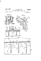
- FIG. 10 is an enlarged sectional View taken on a line through the centers of the series of ports and looking toward the wall of the tank shown in FIGS. 8 and 9;
- FIG. 11 is an enlarged cross-section taken ⁇ on line Il li of FIG. 8 and shows the scum-receiving sump and guides for the control gate shown in FIG. 10;
- FIG. 12 is an enlarged plan view of the sump shown in FIG. 8 and with the plate forming the control gate shown in section.
- the tank 1 of concrete construction shown in FIGS. 1-3 of the drawings includes the circular wall 2 supported on the footing 3 and the tank bottom or door i which slopes downwardly toward the central concrete base S.
- the end of the bridge 6 at the center of the tank is supported on base 5 by a vertical central column, not shown, disposed within the drive tube 7 which is driven by the motor 8.
- Various means for removal of the settled solids from iloor 4 may be provided, including for example, the eduction header 9 supported as shown with the counter-weight 10 by drive tube 7 and hydraulically connected with the discharge pipe 11 at the base 5.
- the effluent trough 12 is supported from bridge 6 at the center of the tank and is connected to the discharge pipe 13 which extends beneath the bridge and through wall 2 of the tank.
- the inlet pipe 15 opens into the box 16 at one side of tank 1 tor delivery of the feed from box 16 to the ends of the channels 17 which extend around the rim of the tank to the scum box 1S located at the opposite side ofthe tank.
- the channels include floors 19 and the inner walls 20 of concrete construction integral with wall 2 of the tank.
- the floor 19 of each channel 17 slopes upwardly in the direction of flow from inlet box 16 and each floor is provided with a series of ports 21 through which the feed is discharged into the distribution zones 2.2.
- the top of wall 2t? is set above the liquid level maintained in the tank by trough 12 so that all the feed to channel 17 is introduced into the tank through ports 21.
- Gate 24 which fits the opening between the shallow ends of channels 17 and the box 18 as shown in FIG. 1.
- Gate 24 comprises a tlat plate having opposite sides slideable in the grooves 2S formed in the concrete wall of the tank to support the gate and normally the gate is disposed in the grooves to close the draw-off opening referred to.
- zones 22, referred to, are located below channels 17 and between wall 2 of tank 1 and the steel annular skirt 26 which extends downwardly and may be supported from walls 20 of the channels.
- the lower edge of skirt 26 is spaced from floor 4 of the tank to provide for introduction of the feed from zones 22 into the main part of the tank for settling or clarification.
- the lower ends of the bailies approach the lower edge of skirt 26 and the upper ends are located between adjacent ports 21 but are spaced from the oor 19 of the channel 17 above the bales.
- the point where each port 21 opens into the corresponding zone 22 is determined by the angularity of the jets at maximum ow. This angularity is due to the velocity maintained in channels 17 to prevent solids from settlin g on the floors of the channel.
- the jets from the ports 21 of each channel have a generally downward direction, but the direction is at a slight angle respecting the vertical so that the flow in zones 22 beneath each channel has a slight horizontal movement around the tank in the direction of the channel ow and toward the higher end of the channel.
- tank 1 In the operation of tank 1, the low velocities in eifect in zones 22 at the borders of the jets allows and promotes the separation of oatable material carried through ports 21. This material rises between the jets and collects beneath iloors 19.
- the material passes from zone to zone over the baii'les 27 which may be spaced only a few inches from floors 19 of the channels and is driven from zone to zone by the slight horizontal movement of the flow which exerts a force against each baille as represented by the arrows 29 in FIG. 7.
- Baflles 27 which separate zones 22 also serve to restrict ow from ports 21 to a downwardly direction without interfering with the balance or equalization of the tiow over the entire series of zones or around the periphery of the tank.
- outlet 28 which may be variously controlled or a separate outlet, not shown, may be provided.
- outlet 28 is normally closed by plate 24 which extends downwardly over the outlet and is opened by lifting plate 24 for discharge into scum box 18.
- the scum collected in box 18 is periodically withdrawn through the drain pipe 30 which may be controlled by a valve or telescopic draw-off means, not shown, or by the removable plug 31 which closes the open end of the pipe in the floor of box 18.
- the embodiment of FIGS. 1 3 is preferred where the scum collects slowly and requires only occasional removal by removing plate 24 for a few moments. The removal of plate 24 allows the scum separately collected at the shallow ends of channels 17 and beneath oors 19 to flow into box 18 and when most of the scum has been removed plate 24 should be replaced.
- the tank 1 may be provided with the open well 34 between the ends of channels 17 as shown in FIGS. 4-6.
- Three sides of the well are of concrete construction and include a part of wall 20 of each channel and the side walls 35 extending to the sump or scum box 36.
- the gate side walls 35 extending to the sump or scum box 35.
- the gate 37 is supported between side walls 35 so as to be removable and to allow the collected scum to flow into box 36.
- the plates 38 which are similar to plate 24 separately provide for the removal of the respective channels 17 as described.
- the tank may be of steel construction such as the tank 40 shown in FIGS. 8-12 of the drawings.
- Tank 40 includes the side wall 41 and conical bottom 42 centrally connected to the pipe 43 for removal of the settled solids therefrom.
- the clarified liquid is removed from the center of the tank through the hood 44 and pipe 45 which opens into the separate box 46 shown in FIG. 9
- the delivery pipe 52 discharges into the steel inlet box 53 which is attached to the tank and opens into the deeper end of channel 49 for introduction of the feed thereto.
- the ow enters the annular distribution zone 54 between skirt 49 and wall 41 through the series of pipes 55 extending downwardly from hoor 48 and in registry with corresponding ports formed in oor 48.
- Pipes 55 are of a length, number and size necessary for the introduction of the flow into zone 54 with the desired amount of horizontal movement and to provide whatever circular motion in tank 40 may be desired, if any.
- the floating material at the surface of the channel flow is driven toward the end of the channel where it collects and the oatable material which is carried through pipes 55 and separates from the jets, rises to the underside of channel oor 48 and moves toward the higher end of the floor.
- the separated material passes between the pipes 55 and skirt 51 or wall 41 of tank 40 to the outlet 56 which is normally closed by the plate 57.
- Plate 57 is vertically movable in the guides 58 and forms the end wall of channel 49 so that when lowered by the handle 59 and the upper edge of the plate is below the liquid level at the end of the channel, the scum ows over the plate into the scum box 60 located adjacent to inlet box 46.
- outlet 56 is uncovered and the material collected beneath channel floor 48 flows through the outlet into the box 60.
- the material is driven through outlet 56 by the head or the liquid level maintained in tank 49 by pipe 47.
- Means not shown, other than plate 57 may be provided to control the withdrawal of the collected scum and oatable material.
- the present invention provides an improved and more useful separation tank and not only eliminates the problem of scum removal from the feed, but promotes the separation of the scum from the feed for a better or clearer tank eluent.
- the peripheral feed tank provides increased capacity.
- the scum separation and collection beneath the channel may be the principal means for scum removal.
- a tank for the separation of oatable and settle able material including means for the withdrawal of clarified liquid from the tank and maintaining a given liquid level within the tank and other means for withdrawal of the settled material therefrom, said tank having an outer wall and an open feed channel extending around the periphery of the tank, said channel having an inlet end and a scum outlet at the opposite end thereof and including a floor sloping upwardly from the inlet end, a skirt extending downwardly from said channel and baffles extending from the tank wall to said skirt defining distribution zones extending in a series around the periphery of the tank and opening at their lower ends into the lower part of the tank, said floor of the channel having a series of ports with each port opening into the upper end of a corresponding zone for the introduction of the feed into the zone in the form of a jet, means beneath said channel at the higher end of the floor thereof for the continuous collection of oatable material separated from the jets in said zones and moving upwardly along the underside of said floor to said means
- a tank for the gravity separation of suspended material including means for the withdrawal of clarified liquid from the tank and maintaining a given liquid level within the tank, said tank having an outer wall and an open feed channel extending around the periphery of the tank, said channel having an inlet end and including a floor sloping upwardly from the inlet end, a skirt extending downwardly from said channel and barks extending from the tank wall to said skirt defining distribution zones extending in a series around the periphery of the tank and opening at their lower ends into the lower part of the tank, said floor of the channel having a series of ports with each port opening into the upper end of a corresponding zone for the introduction of the feed into the zone in the form of a jet, collection means at the higher end of the floor of the channel for the continuous receiving of iioatable material separated from the jets in said zones and moving upwardly along the underside of said iloor to said means, said baffles being spaced from said channel oor for communication between zones at 30 the upper ends thereof for movement of
- an open feed channel extending around the periphery of the tank at said liquid level and having an inlet end and a scum outlet at the opposite end thereof, said channel having a submerged floor sloping upwardly from the inlet to the scum outlet end thereof to provide the channel with a diminishing cross-section and said channel floor having a series of ports opening downwardly, a skirt extending downwardly from said channel and spaced from the wall and floor of the tank, said skirt and tank wall with the channel iloor defining an inverted sloping channel beneath and substantially the length of the channel oor and a feed distribution zone beneath said inverted channel, vertical baffles between adjacent ports and extending from said skirt to said tank wall, said vertical baiiies extending downwardly from an imaginary line spaced below said channel oor and defining the lower limits of said inverted channel and upper limits
Description
June 9, 1964 A, C, LlND ETAL l 3,136,724
PERIPHERAL-FEED CLARIFICATION TANK Filed NOV. 14, 1960 3 Sheets-Sheet 1 June 9, 1964 A. c. LIND ETAL 3,136,724
PERIPHERAL-FEED CLARIFICATION TANK Filed Nov. 14. 1960 3 Smeets-Sheet 3 United States Patent O 3,136,724 PERIPHERAL-FEED CLARIFICATIN TANK Arthur C. Lind, Wauwatosa, and William J. Katz, Fox
Point, Wis., assignors to Chain Belt Company, Milwaukee, Wis., a corporation of Wisconsin Filed Nov. 14, 1960, Ser. No. 68,962 3 Claims. (Cl. 21S-519) This invention relates to clarication and sedimentation tanks and particularly to means providing the improved distribution of influent for Vits introduction into the tank around the periphery thereof, and the separation and collection of the oatable substances from the inuent in the course of such distribution. This application is a continuation in part of the application of the present inventors Serial No. 728,129 and filed April 14, 195 8 for Apparatus for Separation of Liquids or of Solids from a Liquid, now Patent No. 2,961,099.
The distribution means comprises an open channel extending circurnferentially of the tank and is provided with a floor sloping upwardly respecting the ow and having a series of ports opening downwardly into a lower annular distribution zone or zones. The annular distribution zone or zones extending around the tank are located between the wall of the tank and an annular skirt concentric therewith.
The influent is introduced into the open channel at the deeper end thereof and the iloating material in the channel iiow collects at the shallow end of the channel and is removed by suitable means or is allowed to drain into a sump. The floatable material carried with the flow through the ports separates from the borders of the submerged jets in the distribution zone or Zones and rises to the oor of the channel and moves therebeneath toward the higher end of the floor where the material collects `and is readily discharged from the tank.
The principal object of the invention is to utilize the influent and distribution channels of a peripheral-feed tank for the separation of scum and iloatable material from the feed.
Another object of the invention is to provide efficient removal of floatable material in quantities which would not warrant a chain collector mechanism, for example, as where varying amounts of floatable material are received and the larger amounts usually separate out of the feed fairly readily.
Another object of the invention is to provide for the more efficient removal of grease and iloatable solids from a clarification or sedimentation tank or any treatment tank.
Another object is to reduce the maintenance and attention required for `a tank separatingrelatively large quantities of settleable and iloatable solids.
Gther objects and advantages of the invention will appear in the following description of the same as illustrated in the accompanying drawings.
In the drawings: l
FIGURE 1 is a plan view of a primary or secondary sewage treatment tank of concrete construction;
FIG. 2 is a vertical cross-section of the tank shown in FIG, 1 and is taken on lines 2 2 of FIG. 1 and with the 3,136,724 Patented June 9, 1964 FIG. 7 is an enlarged View of some of the distribution zones shown in FIG. 3;
FIG. 8 is a plan View of a steel tank having a hopper bottom for collection of settleable solids and a submerged out et;
FIG. 9 is a sectional view of the tank taken on line 9 9 of FIG. 8 and includes the overflow box which controls the liquid level maintained within the tank;
FIG. 10 is an enlarged sectional View taken on a line through the centers of the series of ports and looking toward the wall of the tank shown in FIGS. 8 and 9;
FIG. 11 is an enlarged cross-section taken` on line Il li of FIG. 8 and shows the scum-receiving sump and guides for the control gate shown in FIG. 10; and
FIG. 12 is an enlarged plan view of the sump shown in FIG. 8 and with the plate forming the control gate shown in section.
The tank 1 of concrete construction shown in FIGS. 1-3 of the drawings includes the circular wall 2 supported on the footing 3 and the tank bottom or door i which slopes downwardly toward the central concrete base S. The end of the bridge 6 at the center of the tank is supported on base 5 by a vertical central column, not shown, disposed within the drive tube 7 which is driven by the motor 8. Various means for removal of the settled solids from iloor 4 may be provided, including for example, the eduction header 9 supported as shown with the counter-weight 10 by drive tube 7 and hydraulically connected with the discharge pipe 11 at the base 5.
The effluent trough 12 is supported from bridge 6 at the center of the tank and is connected to the discharge pipe 13 which extends beneath the bridge and through wall 2 of the tank.
The inlet pipe 15 opens into the box 16 at one side of tank 1 tor delivery of the feed from box 16 to the ends of the channels 17 which extend around the rim of the tank to the scum box 1S located at the opposite side ofthe tank.
In the tank shown, the channels include floors 19 and the inner walls 20 of concrete construction integral with wall 2 of the tank. The floor 19 of each channel 17 slopes upwardly in the direction of flow from inlet box 16 and each floor is provided with a series of ports 21 through which the feed is discharged into the distribution zones 2.2. The top of wall 2t? is set above the liquid level maintained in the tank by trough 12 so that all the feed to channel 17 is introduced into the tank through ports 21. By reason of the diminishing cross-section of channels 17, a given velocity is maintained in the channels so that the tloatable material which separates out in the channel flow is carried or driven toward the shallow end of the channel where it collects until withdrawn. Various meansy for continuously or periodically drawing off the scum or floating material may be provided, including the gate 24 which fits the opening between the shallow ends of channels 17 and the box 18 as shown in FIG. 1. Gate 24 comprises a tlat plate having opposite sides slideable in the grooves 2S formed in the concrete wall of the tank to support the gate and normally the gate is disposed in the grooves to close the draw-off opening referred to.
The zones 22, referred to, are located below channels 17 and between wall 2 of tank 1 and the steel annular skirt 26 which extends downwardly and may be supported from walls 20 of the channels. The lower edge of skirt 26 is spaced from floor 4 of the tank to provide for introduction of the feed from zones 22 into the main part of the tank for settling or clarification.
Zones 22 -are deined by the Vertical bailles 27 which extend from wall 2 of tank l to skirt 26. The lower ends of the bailies approach the lower edge of skirt 26 and the upper ends are located between adjacent ports 21 but are spaced from the oor 19 of the channel 17 above the bales. The point where each port 21 opens into the corresponding zone 22 is determined by the angularity of the jets at maximum ow. This angularity is due to the velocity maintained in channels 17 to prevent solids from settlin g on the floors of the channel.
According to the present invention, the jets from the ports 21 of each channel have a generally downward direction, but the direction is at a slight angle respecting the vertical so that the flow in zones 22 beneath each channel has a slight horizontal movement around the tank in the direction of the channel ow and toward the higher end of the channel.
In the operation of tank 1, the low velocities in eifect in zones 22 at the borders of the jets allows and promotes the separation of oatable material carried through ports 21. This material rises between the jets and collects beneath iloors 19.
The slope of the floors upwardly in the direction of outlet 28 and the slight horizontal movement of the flow in zones 22, as described, which is also in the same direction, effect the movement of the separated material along the underside of the channel floors. The material passes between each jet and the wall 2 or skirt 26. In a tank of the type shown in FIGS. 1-3 the channels 17 are of generally the same Width throughout and a space of six or more inches between each port and the wall 2 easily allows for the movement referred to.
The material passes from zone to zone over the baii'les 27 which may be spaced only a few inches from floors 19 of the channels and is driven from zone to zone by the slight horizontal movement of the flow which exerts a force against each baille as represented by the arrows 29 in FIG. 7. Baflles 27 which separate zones 22 also serve to restrict ow from ports 21 to a downwardly direction without interfering with the balance or equalization of the tiow over the entire series of zones or around the periphery of the tank.
The scum or separated oatable material collects at outlet 28 which may be variously controlled or a separate outlet, not shown, may be provided. As shown in FIG. 2, outlet 28 is normally closed by plate 24 which extends downwardly over the outlet and is opened by lifting plate 24 for discharge into scum box 18.
The scum collected in box 18 is periodically withdrawn through the drain pipe 30 which may be controlled by a valve or telescopic draw-off means, not shown, or by the removable plug 31 which closes the open end of the pipe in the floor of box 18. The embodiment of FIGS. 1 3 is preferred where the scum collects slowly and requires only occasional removal by removing plate 24 for a few moments. The removal of plate 24 allows the scum separately collected at the shallow ends of channels 17 and beneath oors 19 to flow into box 18 and when most of the scum has been removed plate 24 should be replaced.
For collection of larger amounts of floatable material from zones 22, the tank 1 may be provided with the open well 34 between the ends of channels 17 as shown in FIGS. 4-6. Three sides of the well are of concrete construction and include a part of wall 20 of each channel and the side walls 35 extending to the sump or scum box 36. The gate side walls 35 extending to the sump or scum box 35. The gate 37 is supported between side walls 35 so as to be removable and to allow the collected scum to flow into box 36. The plates 38 which are similar to plate 24 separately provide for the removal of the respective channels 17 as described.
In smaller tanks such as for industrial waste treatment or other processes, the tank may be of steel construction such as the tank 40 shown in FIGS. 8-12 of the drawings.
CII
disposed within the box to maintain a given liquid level within tank 4t) which is above the entire length of the oor 48 of the channel 49 extending around the rim of the tank. Floor 48 extends from wall 41 to the concentric inner cylindrical member which it supports and which forms the inner wall 5t) of channel 49 and the lower annular skirt S1.
The delivery pipe 52 discharges into the steel inlet box 53 which is attached to the tank and opens into the deeper end of channel 49 for introduction of the feed thereto. The ow enters the annular distribution zone 54 between skirt 49 and wall 41 through the series of pipes 55 extending downwardly from hoor 48 and in registry with corresponding ports formed in oor 48.
As in the embodiment of the invention of FIGS. 1-7, the floating material at the surface of the channel flow is driven toward the end of the channel where it collects and the oatable material which is carried through pipes 55 and separates from the jets, rises to the underside of channel oor 48 and moves toward the higher end of the floor.
As shown in FIG. l0, the separated material passes between the pipes 55 and skirt 51 or wall 41 of tank 40 to the outlet 56 which is normally closed by the plate 57. Plate 57 is vertically movable in the guides 58 and forms the end wall of channel 49 so that when lowered by the handle 59 and the upper edge of the plate is below the liquid level at the end of the channel, the scum ows over the plate into the scum box 60 located adjacent to inlet box 46. By raising plate 57, outlet 56 is uncovered and the material collected beneath channel floor 48 flows through the outlet into the box 60. The material is driven through outlet 56 by the head or the liquid level maintained in tank 49 by pipe 47. Means not shown, other than plate 57 may be provided to control the withdrawal of the collected scum and oatable material.
The present invention provides an improved and more useful separation tank and not only eliminates the problem of scum removal from the feed, but promotes the separation of the scum from the feed for a better or clearer tank eluent.
The peripheral feed tank provides increased capacity. In tanks having a high channel velocity and large distribution zone beneath the channel, the scum separation and collection beneath the channel may be the principal means for scum removal.
Various embodiments of the invention may be employed within the scope of the following claims particularly pointing out and distinctly claiming the subject matter which is regarded as the invention.
We claim:
l. In a tank for the separation of oatable and settle able material including means for the withdrawal of clarified liquid from the tank and maintaining a given liquid level within the tank and other means for withdrawal of the settled material therefrom, said tank having an outer wall and an open feed channel extending around the periphery of the tank, said channel having an inlet end and a scum outlet at the opposite end thereof and including a floor sloping upwardly from the inlet end, a skirt extending downwardly from said channel and baffles extending from the tank wall to said skirt defining distribution zones extending in a series around the periphery of the tank and opening at their lower ends into the lower part of the tank, said floor of the channel having a series of ports with each port opening into the upper end of a corresponding zone for the introduction of the feed into the zone in the form of a jet, means beneath said channel at the higher end of the floor thereof for the continuous collection of oatable material separated from the jets in said zones and moving upwardly along the underside of said floor to said means, said bafllles being spaced from said channel floor for communication between zones at the upper ends thereof for movement of the floatable material to said continuous collection means, and said tank having an outlet from said collection means and means normally closing said outlet except for the periodic discharge of the collected material.
2. In a tank for the gravity separation of suspended material including means for the withdrawal of clarified liquid from the tank and maintaining a given liquid level within the tank, said tank having an outer wall and an open feed channel extending around the periphery of the tank, said channel having an inlet end and including a floor sloping upwardly from the inlet end, a skirt extending downwardly from said channel and baies extending from the tank wall to said skirt defining distribution zones extending in a series around the periphery of the tank and opening at their lower ends into the lower part of the tank, said floor of the channel having a series of ports with each port opening into the upper end of a corresponding zone for the introduction of the feed into the zone in the form of a jet, collection means at the higher end of the floor of the channel for the continuous receiving of iioatable material separated from the jets in said zones and moving upwardly along the underside of said iloor to said means, said baffles being spaced from said channel oor for communication between zones at 30 the upper ends thereof for movement of the floatable material to said continuous collection means, and means for removal of the floatable material from said collection means.
3. In a tank for the gravity separation of suspended material including a side wall and a floor and means for the withdrawal of claried liquid from the tank and for maintaining a given liquid level therein, an open feed channel extending around the periphery of the tank at said liquid level and having an inlet end and a scum outlet at the opposite end thereof, said channel having a submerged floor sloping upwardly from the inlet to the scum outlet end thereof to provide the channel with a diminishing cross-section and said channel floor having a series of ports opening downwardly, a skirt extending downwardly from said channel and spaced from the wall and floor of the tank, said skirt and tank wall with the channel iloor defining an inverted sloping channel beneath and substantially the length of the channel oor and a feed distribution zone beneath said inverted channel, vertical baffles between adjacent ports and extending from said skirt to said tank wall, said vertical baiiies extending downwardly from an imaginary line spaced below said channel oor and defining the lower limits of said inverted channel and upper limits of said feed distribution zone, and a second, submerged scum outlet extending through the tank wall from the higher end of said inverted channel.
References Cited in the file of this patent UNITED STATES PATENTS 2,103,828 Seip Dec. 28, 1937 2,340,226 Roberts et al lan. 25, 1944 2,418,950 Montgomery Apr. l5, 1947 2,881,922 Kelly Apr. 14, 1959 2,959,290 Montgomery Nov. 8, 1960 2,961,099 Lind et al Nov. 22, 1960 3,017,998 Conley Jan. 23, 1962
Claims (1)
1. IN A TANK FOR THE SEPARATION OF FLOATABLE AND SETTLEABLE MATERIAL INCLUDING MEANS FOR THE WITHDRAWAL OF CLARIFIED LIQUID FROM THE TANK AND MAINTAINING A GIVEN LIQUID LEVEL WITHIN THE TANK AND OTHER MEANS FOR WITHDRAWAL OF THE SETTLED MATERIAL THEREFROM, SAID TANK HAVING AN OUTER WALL AND AN OPEN FEED CHANNEL EXTENDING AROUNG THE PERIPHERY OF THE TANK, SAID CHANNEL EXTENDING AROUND THE PERIPHERY OF THE TANK, SAID CHANNEL HAVNG AN INLET END AND A SCUM OUTLET AT THE OPPOSITE END THEREOF AND INCLUDING A FLOOR SLOPING UPWARDLY FROM THE INLET END, A SKIRT EXTENDING DOWNWARDLY FROM SAID CHANNEL AND BAFFLES EXTENDING FROM THE TANK WALL TO SAID SKIRT DEFINING DISTRIBUTION ZONES EXTENDING IN A SERIES AROUND THE PERIPHERY OF THE TANK AND OPENING AT THEIR LOWER ENDS INTO THE LOWER PART OF THE TANK, SAID FLOOR OF THE CHANNEL HAVING A SERIES OF PORTS WITH EACH PORT OPENING INTO THE UPPER END OF A CORRESPONDING ZONE FOR THE INTRODUCTION OF THE FEED INTO THE ZONE IN THE FORM OF A JET, MEANS BENEATH SAID CHANNEL AT THE HIGHER END OF THE FLOOR THEREOF FOR THE CONTINOUS COLLECTION OF FLOATABLE MATERIAL SEPARATED FROM THE JETS IN SAID ZONES AND MOVING UPWARDLY ALONG THE UNDER SIDE OF SAID FLOOR TO SAID MEANS, SAID BAFFLES BEING SPACED FROM SAID CHANNEL FLOOR FOR COMMUNICATION BETWEEN ZONES AT THE UPPER ENDS THEREOF FOR MOVEMENT OF THE FLOATABLE MATERIAL TO SAID CONTINUOUS COLLECTION MEANS, AND SAID TANK HAVNG AN OUTLET FROM SAID COLLECTION MEANS AND MEANS NORMALLY CLOSING SAID OUTLET EXCEPT FOR THE PERIODIC DISCHARGE OF THE COLLECTED MATERIAL.
Priority Applications (1)
| Application Number | Priority Date | Filing Date | Title |
|---|---|---|---|
| US68962A US3136724A (en) | 1960-11-14 | 1960-11-14 | Peripheral-feed clarification tank |
Applications Claiming Priority (1)
| Application Number | Priority Date | Filing Date | Title |
|---|---|---|---|
| US68962A US3136724A (en) | 1960-11-14 | 1960-11-14 | Peripheral-feed clarification tank |
Publications (1)
| Publication Number | Publication Date |
|---|---|
| US3136724A true US3136724A (en) | 1964-06-09 |
Family
ID=22085830
Family Applications (1)
| Application Number | Title | Priority Date | Filing Date |
|---|---|---|---|
| US68962A Expired - Lifetime US3136724A (en) | 1960-11-14 | 1960-11-14 | Peripheral-feed clarification tank |
Country Status (1)
| Country | Link |
|---|---|
| US (1) | US3136724A (en) |
Cited By (12)
| Publication number | Priority date | Publication date | Assignee | Title |
|---|---|---|---|---|
| US3534861A (en) * | 1969-10-17 | 1970-10-20 | City Of Detroit The | Settling tanks |
| US3891557A (en) * | 1974-02-11 | 1975-06-24 | Fmc Corp | Peripheral feed clarification tank |
| US3966598A (en) * | 1975-02-24 | 1976-06-29 | Tenco Hydro/Aerosciences, Inc. | Circular dissolved gas flotation system |
| US4038185A (en) * | 1976-09-08 | 1977-07-26 | Envirex Inc. | Scum control system for peripheral feed channel of sedimentation tank |
| US4555340A (en) * | 1983-10-26 | 1985-11-26 | Envirex Inc. | Excess overflow orifice tubes |
| US4994187A (en) * | 1988-08-17 | 1991-02-19 | Richard Totzke Mashinen- Und Apparatebaue Gmbh | Apparatus for removing sewage sludge from the bottom or the surface in a settling basin |
| US5116516A (en) * | 1990-03-16 | 1992-05-26 | Hydro International Limited | Gravitational separator for separating solid components out of a liquid mixture |
| US5389250A (en) * | 1991-09-26 | 1995-02-14 | Baker Hughes Incorporated | Self diluting feedwell for thickener dilution |
| WO2000062888A1 (en) * | 1999-04-15 | 2000-10-26 | Hydro International Plc | Hydrodynamic vortex separator |
| US6495035B2 (en) * | 2000-02-18 | 2002-12-17 | Norsk Hydro Asa | Device in connection with a separator |
| US20030173289A1 (en) * | 2002-03-05 | 2003-09-18 | Schoenbrunn Frederick R. | Self diluting feedwell including a vertical eduction mechanism and method of dilution employing same |
| FR2888761A1 (en) * | 2005-07-25 | 2007-01-26 | Otv Sa | GRAVITY SEPARATION DEVICE FOR WATER TREATMENT |
Citations (7)
| Publication number | Priority date | Publication date | Assignee | Title |
|---|---|---|---|---|
| US2103828A (en) * | 1932-12-08 | 1937-12-28 | John J Seip | Process of and apparatus for clarifying liquids |
| US2340226A (en) * | 1941-12-31 | 1944-01-25 | Dorr Co | Sedimentation apparatus |
| US2418950A (en) * | 1944-06-12 | 1947-04-15 | Lakeside Engineering Corp | Settling tank |
| US2881922A (en) * | 1955-10-13 | 1959-04-14 | Process Engineers Inc | Flocculation |
| US2959290A (en) * | 1958-01-17 | 1960-11-08 | Lakeside Engineering Corp | Settling tank with agitating vanes |
| US2961099A (en) * | 1958-04-14 | 1960-11-22 | Chain Belt Co | Apparatus for separation of liquids or of solids from a liquid |
| US3017998A (en) * | 1958-12-12 | 1962-01-23 | Chain Belt Co | Apparatus for separation of solids from a liquid |
-
1960
- 1960-11-14 US US68962A patent/US3136724A/en not_active Expired - Lifetime
Patent Citations (7)
| Publication number | Priority date | Publication date | Assignee | Title |
|---|---|---|---|---|
| US2103828A (en) * | 1932-12-08 | 1937-12-28 | John J Seip | Process of and apparatus for clarifying liquids |
| US2340226A (en) * | 1941-12-31 | 1944-01-25 | Dorr Co | Sedimentation apparatus |
| US2418950A (en) * | 1944-06-12 | 1947-04-15 | Lakeside Engineering Corp | Settling tank |
| US2881922A (en) * | 1955-10-13 | 1959-04-14 | Process Engineers Inc | Flocculation |
| US2959290A (en) * | 1958-01-17 | 1960-11-08 | Lakeside Engineering Corp | Settling tank with agitating vanes |
| US2961099A (en) * | 1958-04-14 | 1960-11-22 | Chain Belt Co | Apparatus for separation of liquids or of solids from a liquid |
| US3017998A (en) * | 1958-12-12 | 1962-01-23 | Chain Belt Co | Apparatus for separation of solids from a liquid |
Cited By (22)
| Publication number | Priority date | Publication date | Assignee | Title |
|---|---|---|---|---|
| US3534861A (en) * | 1969-10-17 | 1970-10-20 | City Of Detroit The | Settling tanks |
| US3891557A (en) * | 1974-02-11 | 1975-06-24 | Fmc Corp | Peripheral feed clarification tank |
| US3966598A (en) * | 1975-02-24 | 1976-06-29 | Tenco Hydro/Aerosciences, Inc. | Circular dissolved gas flotation system |
| US4038185A (en) * | 1976-09-08 | 1977-07-26 | Envirex Inc. | Scum control system for peripheral feed channel of sedimentation tank |
| US4555340A (en) * | 1983-10-26 | 1985-11-26 | Envirex Inc. | Excess overflow orifice tubes |
| US4994187A (en) * | 1988-08-17 | 1991-02-19 | Richard Totzke Mashinen- Und Apparatebaue Gmbh | Apparatus for removing sewage sludge from the bottom or the surface in a settling basin |
| US5116516A (en) * | 1990-03-16 | 1992-05-26 | Hydro International Limited | Gravitational separator for separating solid components out of a liquid mixture |
| US5389250A (en) * | 1991-09-26 | 1995-02-14 | Baker Hughes Incorporated | Self diluting feedwell for thickener dilution |
| US5643463A (en) * | 1991-09-26 | 1997-07-01 | Baker Hughes Incorporated | Self-diluting feedwell for thickener dilution |
| US5893970A (en) * | 1991-09-26 | 1999-04-13 | Baker Hughes Incorporated | Self-diluting feedwell for thickener dilution |
| WO2000062888A1 (en) * | 1999-04-15 | 2000-10-26 | Hydro International Plc | Hydrodynamic vortex separator |
| GB2363739A (en) * | 1999-04-15 | 2002-01-09 | Hydro Int Plc | Hydrodynamic vortex separator |
| GB2363739B (en) * | 1999-04-15 | 2003-05-28 | Hydro Int Plc | Hydrodynamic vortex separator |
| US6730222B1 (en) | 1999-04-15 | 2004-05-04 | Hydro International Plc | Hydrodynamic vortex separator |
| US6495035B2 (en) * | 2000-02-18 | 2002-12-17 | Norsk Hydro Asa | Device in connection with a separator |
| US20030173289A1 (en) * | 2002-03-05 | 2003-09-18 | Schoenbrunn Frederick R. | Self diluting feedwell including a vertical eduction mechanism and method of dilution employing same |
| US6966985B2 (en) | 2002-03-05 | 2005-11-22 | Gl&V Management Hungary Kft | Self-diluting feedwell including a vertical education mechanism |
| FR2888761A1 (en) * | 2005-07-25 | 2007-01-26 | Otv Sa | GRAVITY SEPARATION DEVICE FOR WATER TREATMENT |
| WO2007012633A1 (en) * | 2005-07-25 | 2007-02-01 | Otv Sa | Gravitational separation device for water treatment |
| US20090218300A1 (en) * | 2005-07-25 | 2009-09-03 | Otv Sa | Gravitational Separation Device for Water Treatment |
| US7722776B2 (en) | 2005-07-25 | 2010-05-25 | Otv Sa | Gravitational separation device for water treatment |
| CN101218006B (en) * | 2005-07-25 | 2010-07-28 | Otv股份有限公司 | Gravitational separation device for water treatment |
Similar Documents
| Publication | Publication Date | Title |
|---|---|---|
| US4146471A (en) | Liquid clarification apparatus and method | |
| US4142970A (en) | Method and apparatus for mechanically and chemically treating liquids | |
| CA1251147A (en) | Separation of components of a fluid mixture | |
| US4042512A (en) | Oil water separator | |
| US3136724A (en) | Peripheral-feed clarification tank | |
| US3951816A (en) | Clarification tank | |
| US2314977A (en) | Liquid purification | |
| US4193871A (en) | Clarifier | |
| US4681683A (en) | Lamella gravity separator | |
| US5021153A (en) | Combined apparatus for removing grit and grease from sewage | |
| US2961099A (en) | Apparatus for separation of liquids or of solids from a liquid | |
| KR20120024520A (en) | Wastewater processing device using settling treatment tank for water flow of multiple structural | |
| US2509933A (en) | Clarification of liquids | |
| US2418950A (en) | Settling tank | |
| US5035795A (en) | Modular clarifier with integral flocculator | |
| JPS61185393A (en) | Method and device for biological aerobic waste water treatment | |
| EP0354744A2 (en) | Clarification apparatus | |
| US2678912A (en) | Apparatus for separating grit and grease from waste waters | |
| US2291772A (en) | Combined flocculation and sedimentation apparatus | |
| US2678916A (en) | Apparatus for treating a liquid with a gas | |
| US2322017A (en) | Method and apparatus for treating industrial wastes and sewage | |
| US2483706A (en) | Apparatus for clarifying liquids | |
| US2369194A (en) | Sedimentation apparatus | |
| CN111672166B (en) | Cyclone flotation device | |
| US3710941A (en) | Method and apparatus for treating sewage |