US3008564A - Fast action shifting device - Google Patents
Fast action shifting device Download PDFInfo
- Publication number
- US3008564A US3008564A US784132A US78413258A US3008564A US 3008564 A US3008564 A US 3008564A US 784132 A US784132 A US 784132A US 78413258 A US78413258 A US 78413258A US 3008564 A US3008564 A US 3008564A
- Authority
- US
- United States
- Prior art keywords
- articles
- plunger
- gate
- spring
- oscillatory
- Prior art date
- Legal status (The legal status is an assumption and is not a legal conclusion. Google has not performed a legal analysis and makes no representation as to the accuracy of the status listed.)
- Expired - Lifetime
Links
Images
Classifications
-
- G—PHYSICS
- G06—COMPUTING; CALCULATING OR COUNTING
- G06M—COUNTING MECHANISMS; COUNTING OF OBJECTS NOT OTHERWISE PROVIDED FOR
- G06M7/00—Counting of objects carried by a conveyor
- G06M7/02—Counting of objects carried by a conveyor wherein objects ahead of the sensing element are separated to produce a distinct gap between successive objects
- G06M7/04—Counting of piece goods, e.g. of boxes
-
- G—PHYSICS
- G06—COMPUTING; CALCULATING OR COUNTING
- G06M—COUNTING MECHANISMS; COUNTING OF OBJECTS NOT OTHERWISE PROVIDED FOR
- G06M1/00—Design features of general application
- G06M1/08—Design features of general application for actuating the drive
- G06M1/10—Design features of general application for actuating the drive by electric or magnetic means
- G06M1/101—Design features of general application for actuating the drive by electric or magnetic means by electro-optical means
-
- Y—GENERAL TAGGING OF NEW TECHNOLOGICAL DEVELOPMENTS; GENERAL TAGGING OF CROSS-SECTIONAL TECHNOLOGIES SPANNING OVER SEVERAL SECTIONS OF THE IPC; TECHNICAL SUBJECTS COVERED BY FORMER USPC CROSS-REFERENCE ART COLLECTIONS [XRACs] AND DIGESTS
- Y10—TECHNICAL SUBJECTS COVERED BY FORMER USPC
- Y10S—TECHNICAL SUBJECTS COVERED BY FORMER USPC CROSS-REFERENCE ART COLLECTIONS [XRACs] AND DIGESTS
- Y10S198/00—Conveyors: power-driven
- Y10S198/958—Load units counter
-
- Y—GENERAL TAGGING OF NEW TECHNOLOGICAL DEVELOPMENTS; GENERAL TAGGING OF CROSS-SECTIONAL TECHNOLOGIES SPANNING OVER SEVERAL SECTIONS OF THE IPC; TECHNICAL SUBJECTS COVERED BY FORMER USPC CROSS-REFERENCE ART COLLECTIONS [XRACs] AND DIGESTS
- Y10—TECHNICAL SUBJECTS COVERED BY FORMER USPC
- Y10T—TECHNICAL SUBJECTS COVERED BY FORMER US CLASSIFICATION
- Y10T74/00—Machine element or mechanism
- Y10T74/18—Mechanical movements
- Y10T74/18856—Oscillating to oscillating
- Y10T74/18864—Snap action
Definitions
- This invention provides for an extremely accurate count by shifting a gate substantially instantaneously with the passage of the one hundredth article, or whatever the unit of measurement is, past a given point; and the gate will snap over so that the'one hundred and first article et seq. will take a different selected path from that of the previous predetermined number of articles.
- a commercial electronic counting device made by Veeder- Root Co., in combination with a photo-electric head which is interrupted by the passage of thearticles, regardless of the high speed thereof, said electronic counting ,device accumulating a charge so that whenever the one hundredth article in any series has passed the photo-electric device, an instantaneous relatively small charge is emitted from the counter, this small charge being suflicient to actuate an electric'device for causing actuation of the gate within the space of a very few'milli-seconds.
- the invention also contemplates the use of a trigger device which is substantially instantaneously operated by the charge of the electronic counter above referred to, said trigger device being pre-loaded so that upon being released, it is instantly transferred from one location to another, thereby mechanically operating the gate; and the provision of electrically operated and timed means for preloading the trigger means in each position so that it is ready for uniform actuation thereof upon being released by'the electronic counter-operated device.
- the invention further relates to arrangements and 3,008,564 Patented Nov. 14, 1961 lines, each of which receives exactly one-half of the number of articles on the belt, these two lines being appropriately moved forwardly in separate alleys or troughs indicated at 16 and 18 respectively.
- the separating gate is illustrated generally by the reference numeral 20, and it will be seen in FIG. 1 that it is operated by means of a yoke 22 connected to an arm 24 of what amounts to a bell crank adapted to oscillate on an upright shaft 26 in a boss 27. As the yoke moves right and left in FIG. 1, the separating gate 20 will be moved between'dotted and solid line representations thereof in order to shift the oncoming articles 10 to one side or the other toenter the appropriate trough 16 or 18. v
- a photo-electric head generally indicated at 28 and perhaps best shown diagrammatically in FIG. 4, provides a beam optically directed to a very small area intermediate the two ends of the head, thesebeing indicated at 30 and 32, so that as each article passes the head and interrupts the light, an electronic device is actuated in the commercial electronic. counter generally indicated by the reference numeral 34.
- This counter is a commercial device made by Veeder Root Co. and is well known in the art. Its function is to discharge electrically upon the completion of a certain predetermined number of impulses from the photoelectric head, such impulses being occasioned bythe passage'of the articles or tablets 10 past the head. These electronic counters may be set to be actuated at an adjustable predetermined number of impulses from the head.
- the electronic computer 34 is connected to operate a solenoid which is shown diagrammatically in FIG. 4 and indicated by the reference numeral 36.
- This solenoid is shown mechanically in FIG. 2 and when it is actuated it pulls a link 38 to the right.
- This link in this case oscillates a link 40, the latter being spring-pressed as at 42 to normally maintain a left-hand position (FIG. 2), but being momentarily withdrawn to the right upon the discharge of an, electric impulse from the electronic counter after each selected unit or number of articles has passed the photoelectric head 28.
- Arm 40 may be pivoted conveniently as at 44 and is provided with a small projection 46 which cooperates with a similar projection 48 on a swinging oscillatory element 50.
- This element 50 is mounted to in turn oscillate a shaft 52 directly connected to the yoke 22, the upper end of which is seen in dotted lines in FIG. 1.
- the oscillating element 50 is provided with a pair of horns such as at 54 and these may be concave to alternately accommodate-a roller 58 on the end of a plunger 60 mounted telescopingly for instance in an oscillating sleeve 62 and projected by a compressive spring 64 constantly in a directionto engage combinations of parts which will be hereinafter described and more particularly set forth in the appended claims.
- FIG. 1 is a top plan view showing the device
- FIG. 2 is an elevational'view on line 22 of FIG. 1
- FIG. 3 is 'a section on line33 of FIG. 2;
- FIG. 4 is a diagrammatic representation of the photoelectric counting device.
- this invention may be applied to operate any kind of device which might be desired or convenient to the inventive concept herein, it is here shown as applied to a line of articles 10 which are traveling at a very high rate of ,SPeed on the belt 12,. movingin the direction of arrow 14 in FIG. 1, and separatingthe same into two the concave portions 54, 54 of said horns.
- Solenoids 66 and 68 are operated in timed relation to the passage of the articles by any kind of automatic switch means 76 which may be desired or convenient.
- a cam 78' which operates the switch and a like cam or the same one'may be used to actuate solenoid 68.
- these solenoids are electrically operated and are placed in timed relation to the passage of the units of articles.
- the operation of these solenoids is not particularly critical, as they may operate as stated at any time between the passage from start to finish of the particular number of articles which are to be transferred to one chute or the other at 16-, 18.
- plunger 60 be inposition and spring-loaded in order to snap the oscillating element 50 from one position to the other substantially instantaneously upon release of projection 48 by'projection 46 no matter whether the oscillating element 50 is set to move clockwise or counter-clockwise.
- the solenoid at 36 is a direct-current solenoid but those at 66 and 68 may be operated by alternating cur rent, and it is particularly emphasized that the electric charge by the electronic counter 34 is sufficient toactuate the solenoid 36 instantaneously upon the passage of the, say fifty or one hundred articles, so that the spring 64 then operates 'the'os'cillating device 50 also substantially instantaneously.
- the spring 64' is'always loaded to the same degree'and it is asi'ngl'e member'which operates'thesame in both directions in order to spring load the oscillating gate actuator member 50.
- a device of the class described comprisingmeans for rapidly moving in line a series of articles,"rneans counting the articles, a swinging gate-like elementfor directings-aid line of articles in predetermined numbers in 'a'plurality of directions from said original line, and means to actuate said gate-like element comprising a movable memberconnected to the element, a springloaded plunger bearing onsaid movablememb'er and adapted to move the same in a predetermined direction, said plunger'being movable to engage a difierent portion of said member to move it in another direction, releasable means holding said member against motion in any direction, and means to operate said holding means to release the same substantially instantaneously upon the passage of a certain predetermined number of articles past said counting means.
- means to actuate said gate-like element comprising a movable member connected to the element, a springloaded plunger bearing on said movable member and adapted to move the same in. a predetermined direction, said plunger being movable to engage a different portion of said member to move it in another direction,- releasable means holding said member against motion in-any direction, and means to operate said holding means to release the same substantially instantaneously u'pon the passage of a certain predetermined number of articles past said counting means, and means operatively arranged between the counting means and the releasing means to actuate the latter after the predetermined number of articles has passed the counting means.
- a device of the class described comprising means for rapidly moving in line a series of articles, means counting the articles, a swinging gate-like element for directing said line of articles in predeterinined'numbers in a plurality of directions from said original line, and means to actuate said gate-like element comprising a movable member connected to the element, a springloaded plunger bearing on said movable member and adapted to move the same in a predetermined direction, said plunger being movable to engage a difierent portion of said member to move it in another direction, releasable means holding said member against motion in any direction, and means to operate said holding means to release the same substantially instantaneously upon the passage of a certain predetermined number of articles past said counting means, and means operatively arrangedv between the counting means and the releasing means to actuate the latter after the predetermined number of articles has passed the counting means, and means for moving the plunger in timed relation to the actuation of the movable member.
- a device of theclass described comprising means providing for a single line of articles to advance seriatim, a shifta'ble element directing said articles into a plurality of paths, means to shift said element accurately and quickly upon the passage past a certain point of a certain predetermined number of said articles, an oscillatory member connected to said elementfor moving it,- an oscillatory plunger including a spring-loaded member engaged'with a certain portion of said oscillatory member and constantly tending to move the same in a direction to move the shiftable element in either direction, means holding said oscillatory member against the action thereof, and means for releasing said holding means upon the passage of a predetermined number of said articles.
- a device of the class described comprising means providing for a single line of articles to advance seriati-m, a shiftable element directing said articles into a plurality of paths, means to shift said element accurately and quickly upon the passage past a certain point of a certain predetermined number of said articles, an oscillatory member connected to said element for moving it, an oscillatory plunger including a spring-loaded member engaged with a certain portion of said oscillatory member and constantly tending to move the same in a direction to actuate the shiftable element from one position to another, means holding said oscillatory member against the action thereof, mean for releasing said holding means upon the, passage of a predetermined number of said articles, and means shifting said spring-loaded plunger and its member to again engage said oscillatory member to tend to move the same in a reverse direction, said holding means being actuated to hold the oscillatory member against the action ofsaid spring-loaded plunger until the releasing means is once more actuated;
- said releasing means comprising a direct-current solenoid and means to actuate the same
- said last-named means comprising an electronic counter deriving its action from a photo-electric head adapted to count the progress of a moving line of articles, said movable gate-like element being moved to shift a certain predetermined number of said articles into different paths.
- means for progrossing a line of aligned articles in single file past a given point electric means counting the same, a swinging gate-like element for dividing said single line of articles into a plurality of lines, and means to operate said gate-like element comprising an oscillatory member, a pair of abutments thereon in mutually spaced relation, a plunger, a spring for said plunger moving the same toward said oscillatory member in general between said two abutments, means for locating said plunger against one or the other abutment selectively, thus in effect springloading the oscillatory member to tend to cause it to move in one direction or the other, a releasable stop, means on said oscillatory member and in engagement with the releasable stop holding the oscillatory member releasably in either position of extreme oscillation thereof, and "means to actuate the stop to release the oscillatory member.
- a device of the class described means for progressing a line of aligned articles in single file past a given point, electric means counting the same, a swinging gate-like element for dividing said single line of articles into a plurality of lines, and means to operate said gate-like element comprising an oscillatory member, a pair of abutments thereon in mutually spaced relation, a plunger, a spring for said plunger moving the same toward said oscillatory member in general between said two abutments, means for locating said plunger against one or the other abutment selectively, thus in eflfect spring-loading the oscillatory member to .tend to cause it to move in one direction or the other, a releasable stop, means on said oscillatory member and in engagement with the releasable stop holding the oscillatory member releasably in either extreme of its oscillatory motion, and means to move said plunger from one abutment toward the other in timed relation subsequently to the stopping action
Description
United States Patent 7 3,008,564 FAST ACTION SHIFTING DEVICE Eino E. Lakso, Fitchburg, Mass., assignor to The Lakso Company Incorporated, Fitchburg, Mass., a corporation of Massachusetts Filed Dec. 31, 1958, Ser. No. 784,132 9 Claims. (Cl. 19831) This invention relates to a new and improved extreme 1y fast acting shifting device which in this case is particu' larly adapted to a gate for dividing a high speed single line of on-coming articles to either of two or more different selected paths for the purpose of counting the articles and packaging the same. As an illustration, the invention may be used for a packaging apparatus for tablets, pills, etc., and for any small articles.
In devices of this nature, it is very diflicult to obtain an automatic proper count of the articles which are to be packaged. It is clearly necessary to havefatleast one hundred tablets in a bottle which contains a label to the effect that there are one hundred tablets therein, but it is very diflicult to present exactly one hundred tablets at each filling, and if the counting apparatus operates a few .milli-seconds too slow, the error may be great enough to provide anywhere from e.g., ninety-seven to one-hundred and-three tablets. One reason for this is that modern packaging machines operate at a very high speed.
This invention provides for an extremely accurate count by shifting a gate substantially instantaneously with the passage of the one hundredth article, or whatever the unit of measurement is, past a given point; and the gate will snap over so that the'one hundred and first article et seq. will take a different selected path from that of the previous predetermined number of articles.
In carrying out the present invention, use is made of a commercial electronic counting device made by Veeder- Root Co., in combination with a photo-electric head which is interrupted by the passage of thearticles, regardless of the high speed thereof, said electronic counting ,device accumulating a charge so that whenever the one hundredth article in any series has passed the photo-electric device, an instantaneous relatively small charge is emitted from the counter, this small charge being suflicient to actuate an electric'device for causing actuation of the gate within the space of a very few'milli-seconds. v
The invention also contemplates the use of a trigger device which is substantially instantaneously operated by the charge of the electronic counter above referred to, said trigger device being pre-loaded so that upon being released, it is instantly transferred from one location to another, thereby mechanically operating the gate; and the provision of electrically operated and timed means for preloading the trigger means in each position so that it is ready for uniform actuation thereof upon being released by'the electronic counter-operated device.
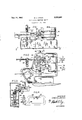
The invention further relates to arrangements and 3,008,564 Patented Nov. 14, 1961 lines, each of which receives exactly one-half of the number of articles on the belt, these two lines being appropriately moved forwardly in separate alleys or troughs indicated at 16 and 18 respectively. The separating gate is illustrated generally by the reference numeral 20, and it will be seen in FIG. 1 that it is operated by means of a yoke 22 connected to an arm 24 of what amounts to a bell crank adapted to oscillate on an upright shaft 26 in a boss 27. As the yoke moves right and left in FIG. 1, the separating gate 20 will be moved between'dotted and solid line representations thereof in order to shift the oncoming articles 10 to one side or the other toenter the appropriate trough 16 or 18. v
A photo-electric head generally indicated at 28 and perhaps best shown diagrammatically in FIG. 4, provides a beam optically directed to a very small area intermediate the two ends of the head, thesebeing indicated at 30 and 32, so that as each article passes the head and interrupts the light, an electronic device is actuated in the commercial electronic. counter generally indicated by the reference numeral 34.
This counter is a commercial device made by Veeder Root Co. and is well known in the art. Its function is to discharge electrically upon the completion of a certain predetermined number of impulses from the photoelectric head, such impulses being occasioned bythe passage'of the articles or tablets 10 past the head. These electronic counters may be set to be actuated at an adjustable predetermined number of impulses from the head.
The electronic computer 34 is connected to operate a solenoid which is shown diagrammatically in FIG. 4 and indicated by the reference numeral 36. This solenoid is shown mechanically in FIG. 2 and when it is actuated it pulls a link 38 to the right. This link in this case oscillates a link 40, the latter being spring-pressed as at 42 to normally maintain a left-hand position (FIG. 2), but being momentarily withdrawn to the right upon the discharge of an, electric impulse from the electronic counter after each selected unit or number of articles has passed the photoelectric head 28. Arm 40 may be pivoted conveniently as at 44 and is provided with a small projection 46 which cooperates with a similar projection 48 on a swinging oscillatory element 50. This element 50 is mounted to in turn oscillate a shaft 52 directly connected to the yoke 22, the upper end of which is seen in dotted lines in FIG. 1. i The oscillating element 50 is provided with a pair of horns such as at 54 and these may be concave to alternately accommodate-a roller 58 on the end of a plunger 60 mounted telescopingly for instance in an oscillating sleeve 62 and projected by a compressive spring 64 constantly in a directionto engage combinations of parts which will be hereinafter described and more particularly set forth in the appended claims.
Reference is to be had to theaccompanying drawings, in which: i f
FIG. 1 is a top plan view showing the device;
FIG. 2 is an elevational'view on line 22 of FIG. 1
FIG. 3 is 'a section on line33 of FIG. 2; and
FIG. 4 is a diagrammatic representation of the photoelectric counting device.
Although this invention may be applied to operate any kind of device which might be desired or convenient to the inventive concept herein, it is here shown as applied to a line of articles 10 which are traveling at a very high rate of ,SPeed on the belt 12,. movingin the direction of arrow 14 in FIG. 1, and separatingthe same into two the concave portions 54, 54 of said horns.
It will therefore be seen with the mechanism set as in. FIG. 2, and projection 46 engaging projection 48, the element 50 is held thereby in the position shown, against the action of the spring 64 which is tending to move element 50 in a clockwise direction, Therefore, when the link 40 is withdrawn to the right, under influence of solenoid 36, and freeing'projection 48 and thereby member 50, the spring 64 acts on plunger 60 to snap member 50 from theposition shown in FIG. 2 to an opposed inclined position sufiicient to turn shaft 52, yoke 22, etc., to move the gate from the solid line to the dotted line position in FIG. 1. V The reverse action is'also accomplished in exactlythe same way but in this case projection 48 is naturally now 3 means for oscillating the member 62 and this is donein this case by means of a pair of solenoids which are indicated at 66 and 68, these being connected by respective links 70, 72 to the member 62, which is pivoted at 74.
The solenoid at 36 is a direct-current solenoid but those at 66 and 68 may be operated by alternating cur rent, and it is particularly emphasized that the electric charge by the electronic counter 34 is sufficient toactuate the solenoid 36 instantaneously upon the passage of the, say fifty or one hundred articles, so that the spring 64 then operates 'the'os'cillating device 50 also substantially instantaneously. v
It is pointed out that the invention above described pro.- vides a construction which is as accurate and as quick an acting device as may be made, for the reason that if a direct charge from the counte'r 34 is notused directly onto the D.C.- solenoid'3 6, then the delay in the action of sum solenoid (or any A.C. solenoid) is such as to cause a variation in the time element which will cause a variation in the action of the separating gateand a consequent variation in the numberpf articles counter; However, the spring 64' is'always loaded to the same degree'and it is asi'ngl'e member'which operates'thesame in both directions in order to spring load the oscillating gate actuator member 50. Variations in the solenoids66 an 68 are ini'material'because they do not act upon the gate directly in any way at all but merely move the member 60 to exposition where it becomes spring-loaded to exactly the same degree for each actuation of the device, as is necessary to accompnsn'an accurate actuation of the separating gate for each number of articles that it is desired to be separated;
Having thus described'my invention a'ndthe advantages thereof, I as not wish to be limited to the details'h'erein disclosed, otherwise'than as set forth in the claims, but what Ienim is:
1. A device of the class described comprisingmeans for rapidly moving in line a series of articles,"rneans counting the articles, a swinging gate-like elementfor directings-aid line of articles in predetermined numbers in 'a'plurality of directions from said original line, and means to actuate said gate-like element comprising a movable memberconnected to the element, a springloaded plunger bearing onsaid movablememb'er and adapted to move the same in a predetermined direction, said plunger'being movable to engage a difierent portion of said member to move it in another direction, releasable means holding said member against motion in any direction, and means to operate said holding means to release the same substantially instantaneously upon the passage of a certain predetermined number of articles past said counting means. i
2. A device of the class described'comprising means for rapidlymoving in line a series'of articles, means counting the articles, a swinging gate-like element for directing said line of articles in predetermined numbers in a plurality of directions from said original line, and
means to actuate said gate-like element comprising a movable member connected to the element, a springloaded plunger bearing on said movable member and adapted to move the same in. a predetermined direction, said plunger being movable to engage a different portion of said member to move it in another direction,- releasable means holding said member against motion in-any direction, and means to operate said holding means to release the same substantially instantaneously u'pon the passage of a certain predetermined number of articles past said counting means, and means operatively arranged between the counting means and the releasing means to actuate the latter after the predetermined number of articles has passed the counting means.
3. A device of the class described comprising means for rapidly moving in line a series of articles, means counting the articles, a swinging gate-like element for directing said line of articles in predeterinined'numbers in a plurality of directions from said original line, and means to actuate said gate-like element comprising a movable member connected to the element, a springloaded plunger bearing on said movable member and adapted to move the same in a predetermined direction, said plunger being movable to engage a difierent portion of said member to move it in another direction, releasable means holding said member against motion in any direction, and means to operate said holding means to release the same substantially instantaneously upon the passage of a certain predetermined number of articles past said counting means, and means operatively arrangedv between the counting means and the releasing means to actuate the latter after the predetermined number of articles has passed the counting means, and means for moving the plunger in timed relation to the actuation of the movable member.
4. The device of claim 3 wherein the last-named means includes solenoids connected to the plunger.
5. A device of theclass described comprising means providing for a single line of articles to advance seriatim, a shifta'ble element directing said articles into a plurality of paths, means to shift said element accurately and quickly upon the passage past a certain point of a certain predetermined number of said articles, an oscillatory member connected to said elementfor moving it,- an oscillatory plunger including a spring-loaded member engaged'with a certain portion of said oscillatory member and constantly tending to move the same in a direction to move the shiftable element in either direction, means holding said oscillatory member against the action thereof, and means for releasing said holding means upon the passage of a predetermined number of said articles.
6. A device of the class described comprising means providing for a single line of articles to advance seriati-m, a shiftable element directing said articles into a plurality of paths, means to shift said element accurately and quickly upon the passage past a certain point of a certain predetermined number of said articles, an oscillatory member connected to said element for moving it, an oscillatory plunger including a spring-loaded member engaged with a certain portion of said oscillatory member and constantly tending to move the same in a direction to actuate the shiftable element from one position to another, means holding said oscillatory member against the action thereof, mean for releasing said holding means upon the, passage of a predetermined number of said articles, and means shifting said spring-loaded plunger and its member to again engage said oscillatory member to tend to move the same in a reverse direction, said holding means being actuated to hold the oscillatory member against the action ofsaid spring-loaded plunger until the releasing means is once more actuated;
7. The combination of a movable gate-like element and means to 'move the same, said means comprising an oscillatory member, means mounting themernbe'r on its oscillatory axis, spring-loaded means engaging the mem;
ber in positions of the member wherein it is ready to be oscillated by the spring-loaded means, and means holding said member against the action of said spring-loaded means, with means to release said holding means, said releasing means comprising a direct-current solenoid and means to actuate the same, said last-named means comprising an electronic counter deriving its action from a photo-electric head adapted to count the progress of a moving line of articles, said movable gate-like element being moved to shift a certain predetermined number of said articles into different paths.
8. In a device of the class described, means for progrossing a line of aligned articles in single file past a given point, electric means counting the same, a swinging gate-like element for dividing said single line of articles into a plurality of lines, and means to operate said gate-like element comprising an oscillatory member, a pair of abutments thereon in mutually spaced relation, a plunger, a spring for said plunger moving the same toward said oscillatory member in general between said two abutments, means for locating said plunger against one or the other abutment selectively, thus in effect springloading the oscillatory member to tend to cause it to move in one direction or the other, a releasable stop, means on said oscillatory member and in engagement with the releasable stop holding the oscillatory member releasably in either position of extreme oscillation thereof, and "means to actuate the stop to release the oscillatory member.
9. In a device of the class described, means for progressing a line of aligned articles in single file past a given point, electric means counting the same, a swinging gate-like element for dividing said single line of articles into a plurality of lines, and means to operate said gate-like element comprising an oscillatory member, a pair of abutments thereon in mutually spaced relation, a plunger, a spring for said plunger moving the same toward said oscillatory member in general between said two abutments, means for locating said plunger against one or the other abutment selectively, thus in eflfect spring-loading the oscillatory member to .tend to cause it to move in one direction or the other, a releasable stop, means on said oscillatory member and in engagement with the releasable stop holding the oscillatory member releasably in either extreme of its oscillatory motion, and means to move said plunger from one abutment toward the other in timed relation subsequently to the stopping action of the releasable stop.
Jefirey Jan. 27, 1942 Roop May 15, 1954
Priority Applications (1)
| Application Number | Priority Date | Filing Date | Title |
|---|---|---|---|
| US784132A US3008564A (en) | 1958-12-31 | 1958-12-31 | Fast action shifting device |
Applications Claiming Priority (1)
| Application Number | Priority Date | Filing Date | Title |
|---|---|---|---|
| US784132A US3008564A (en) | 1958-12-31 | 1958-12-31 | Fast action shifting device |
Publications (1)
| Publication Number | Publication Date |
|---|---|
| US3008564A true US3008564A (en) | 1961-11-14 |
Family
ID=25131444
Family Applications (1)
| Application Number | Title | Priority Date | Filing Date |
|---|---|---|---|
| US784132A Expired - Lifetime US3008564A (en) | 1958-12-31 | 1958-12-31 | Fast action shifting device |
Country Status (1)
| Country | Link |
|---|---|
| US (1) | US3008564A (en) |
Cited By (9)
| Publication number | Priority date | Publication date | Assignee | Title |
|---|---|---|---|---|
| US3139965A (en) * | 1960-11-07 | 1964-07-07 | Fmc Corp | High speed sorting apparatus |
| US3193078A (en) * | 1963-01-18 | 1965-07-06 | Emhart Corp | Article divider for conveyors |
| US3241651A (en) * | 1964-03-04 | 1966-03-22 | Emhart Corp | Carton diverting apparatus |
| US3321064A (en) * | 1964-06-17 | 1967-05-23 | Deering Milliken Res Corp | Automatic bobbin supply system |
| US3355002A (en) * | 1965-10-11 | 1967-11-28 | American Flange & Mfg | Method and apparatus for dividing the flow of articles |
| US4078652A (en) * | 1976-06-25 | 1978-03-14 | Computron, Inc. | Article feeder |
| US5761883A (en) * | 1995-11-28 | 1998-06-09 | Food Machinery Sales, Inc. | Cookie tray loading machine |
| US6131720A (en) * | 1996-11-25 | 2000-10-17 | Heuft Systemtechnik Gmbh | Device for separating individual or a plurality of rotationally symmetric containers under backup pressure |
| US20050247542A1 (en) * | 2004-05-05 | 2005-11-10 | Paolo Salvoni | Diverter |
Citations (2)
| Publication number | Priority date | Publication date | Assignee | Title |
|---|---|---|---|---|
| US2270951A (en) * | 1941-04-25 | 1942-01-27 | Max L Jeffrey | Switch |
| US2679317A (en) * | 1946-10-25 | 1954-05-25 | Automatic X Ray Corp | Inspecting method and apparatus |
-
1958
- 1958-12-31 US US784132A patent/US3008564A/en not_active Expired - Lifetime
Patent Citations (2)
| Publication number | Priority date | Publication date | Assignee | Title |
|---|---|---|---|---|
| US2270951A (en) * | 1941-04-25 | 1942-01-27 | Max L Jeffrey | Switch |
| US2679317A (en) * | 1946-10-25 | 1954-05-25 | Automatic X Ray Corp | Inspecting method and apparatus |
Cited By (10)
| Publication number | Priority date | Publication date | Assignee | Title |
|---|---|---|---|---|
| US3139965A (en) * | 1960-11-07 | 1964-07-07 | Fmc Corp | High speed sorting apparatus |
| US3193078A (en) * | 1963-01-18 | 1965-07-06 | Emhart Corp | Article divider for conveyors |
| US3241651A (en) * | 1964-03-04 | 1966-03-22 | Emhart Corp | Carton diverting apparatus |
| US3321064A (en) * | 1964-06-17 | 1967-05-23 | Deering Milliken Res Corp | Automatic bobbin supply system |
| US3355002A (en) * | 1965-10-11 | 1967-11-28 | American Flange & Mfg | Method and apparatus for dividing the flow of articles |
| US4078652A (en) * | 1976-06-25 | 1978-03-14 | Computron, Inc. | Article feeder |
| US5761883A (en) * | 1995-11-28 | 1998-06-09 | Food Machinery Sales, Inc. | Cookie tray loading machine |
| US6131720A (en) * | 1996-11-25 | 2000-10-17 | Heuft Systemtechnik Gmbh | Device for separating individual or a plurality of rotationally symmetric containers under backup pressure |
| US20050247542A1 (en) * | 2004-05-05 | 2005-11-10 | Paolo Salvoni | Diverter |
| US6981581B2 (en) * | 2004-05-05 | 2006-01-03 | Cfs Palazzolo S.P.A. | Diverter |
Similar Documents
| Publication | Publication Date | Title |
|---|---|---|
| US2632588A (en) | Counting and packaging apparatus | |
| US3008564A (en) | Fast action shifting device | |
| FR2401470A1 (en) | COIN STAMP DETECTOR FOR COINS SORTING MACHINE | |
| GB1082408A (en) | Cop orientating apparatus | |
| US2192503A (en) | Work feeding device | |
| US2371126A (en) | Apparatus for feeding-articles from | |
| US3018595A (en) | Package filling apparatus | |
| US2763108A (en) | Counting and packaging machines | |
| US3347249A (en) | Method and device of counting coins | |
| US2985283A (en) | Motor control means for spotting mechanism | |
| US1994550A (en) | Scale | |
| US2609947A (en) | Package distribution system | |
| US1784540A (en) | Weight-checking device | |
| US2353005A (en) | Automatic packaging machine | |
| US1737877A (en) | Machine for counting and packaging articles | |
| US2671589A (en) | Article counting and filling | |
| US3695279A (en) | High speed coin counting and sorting | |
| US1619787A (en) | Machine for checkweighing and grading by weight | |
| US2324901A (en) | Spring feeding apparatus | |
| US3085640A (en) | Automatic conveyor and weighing scale system | |
| US2899784A (en) | Method and apparatus for counting and packaging articles | |
| US1668717A (en) | Counter | |
| GB338714A (en) | Improvements in machine for counting and packaging articles | |
| US2601787A (en) | Sheetsxsheet i | |
| GB921401A (en) | Improvements in or relating to devices for releasing articles one at a time from chute-like supports |