US20160046292A1 - Charge control device, vehicle control device, vehicle, charge control method and vehicle control method - Google Patents
Charge control device, vehicle control device, vehicle, charge control method and vehicle control method Download PDFInfo
- Publication number
- US20160046292A1 US20160046292A1 US14/778,676 US201314778676A US2016046292A1 US 20160046292 A1 US20160046292 A1 US 20160046292A1 US 201314778676 A US201314778676 A US 201314778676A US 2016046292 A1 US2016046292 A1 US 2016046292A1
- Authority
- US
- United States
- Prior art keywords
- auxiliary machinery
- battery
- vehicle
- engine
- soc
- Prior art date
- Legal status (The legal status is an assumption and is not a legal conclusion. Google has not performed a legal analysis and makes no representation as to the accuracy of the status listed.)
- Granted
Links
Images


Classifications
-
- F—MECHANICAL ENGINEERING; LIGHTING; HEATING; WEAPONS; BLASTING
- F02—COMBUSTION ENGINES; HOT-GAS OR COMBUSTION-PRODUCT ENGINE PLANTS
- F02D—CONTROLLING COMBUSTION ENGINES
- F02D29/00—Controlling engines, such controlling being peculiar to the devices driven thereby, the devices being other than parts or accessories essential to engine operation, e.g. controlling of engines by signals external thereto
- F02D29/06—Controlling engines, such controlling being peculiar to the devices driven thereby, the devices being other than parts or accessories essential to engine operation, e.g. controlling of engines by signals external thereto peculiar to engines driving electric generators
-
- B—PERFORMING OPERATIONS; TRANSPORTING
- B60—VEHICLES IN GENERAL
- B60W—CONJOINT CONTROL OF VEHICLE SUB-UNITS OF DIFFERENT TYPE OR DIFFERENT FUNCTION; CONTROL SYSTEMS SPECIALLY ADAPTED FOR HYBRID VEHICLES; ROAD VEHICLE DRIVE CONTROL SYSTEMS FOR PURPOSES NOT RELATED TO THE CONTROL OF A PARTICULAR SUB-UNIT
- B60W30/00—Purposes of road vehicle drive control systems not related to the control of a particular sub-unit, e.g. of systems using conjoint control of vehicle sub-units, or advanced driver assistance systems for ensuring comfort, stability and safety or drive control systems for propelling or retarding the vehicle
- B60W30/18—Propelling the vehicle
- B60W30/188—Controlling power parameters of the driveline, e.g. determining the required power
- B60W30/1886—Controlling power supply to auxiliary devices
-
- B—PERFORMING OPERATIONS; TRANSPORTING
- B60—VEHICLES IN GENERAL
- B60W—CONJOINT CONTROL OF VEHICLE SUB-UNITS OF DIFFERENT TYPE OR DIFFERENT FUNCTION; CONTROL SYSTEMS SPECIALLY ADAPTED FOR HYBRID VEHICLES; ROAD VEHICLE DRIVE CONTROL SYSTEMS FOR PURPOSES NOT RELATED TO THE CONTROL OF A PARTICULAR SUB-UNIT
- B60W10/00—Conjoint control of vehicle sub-units of different type or different function
- B60W10/04—Conjoint control of vehicle sub-units of different type or different function including control of propulsion units
- B60W10/06—Conjoint control of vehicle sub-units of different type or different function including control of propulsion units including control of combustion engines
-
- B—PERFORMING OPERATIONS; TRANSPORTING
- B60—VEHICLES IN GENERAL
- B60W—CONJOINT CONTROL OF VEHICLE SUB-UNITS OF DIFFERENT TYPE OR DIFFERENT FUNCTION; CONTROL SYSTEMS SPECIALLY ADAPTED FOR HYBRID VEHICLES; ROAD VEHICLE DRIVE CONTROL SYSTEMS FOR PURPOSES NOT RELATED TO THE CONTROL OF A PARTICULAR SUB-UNIT
- B60W10/00—Conjoint control of vehicle sub-units of different type or different function
- B60W10/24—Conjoint control of vehicle sub-units of different type or different function including control of energy storage means
- B60W10/26—Conjoint control of vehicle sub-units of different type or different function including control of energy storage means for electrical energy, e.g. batteries or capacitors
-
- B—PERFORMING OPERATIONS; TRANSPORTING
- B60—VEHICLES IN GENERAL
- B60W—CONJOINT CONTROL OF VEHICLE SUB-UNITS OF DIFFERENT TYPE OR DIFFERENT FUNCTION; CONTROL SYSTEMS SPECIALLY ADAPTED FOR HYBRID VEHICLES; ROAD VEHICLE DRIVE CONTROL SYSTEMS FOR PURPOSES NOT RELATED TO THE CONTROL OF A PARTICULAR SUB-UNIT
- B60W10/00—Conjoint control of vehicle sub-units of different type or different function
- B60W10/30—Conjoint control of vehicle sub-units of different type or different function including control of auxiliary equipment, e.g. air-conditioning compressors or oil pumps
-
- F—MECHANICAL ENGINEERING; LIGHTING; HEATING; WEAPONS; BLASTING
- F02—COMBUSTION ENGINES; HOT-GAS OR COMBUSTION-PRODUCT ENGINE PLANTS
- F02D—CONTROLLING COMBUSTION ENGINES
- F02D17/00—Controlling engines by cutting out individual cylinders; Rendering engines inoperative or idling
- F02D17/02—Cutting-out
-
- F—MECHANICAL ENGINEERING; LIGHTING; HEATING; WEAPONS; BLASTING
- F02—COMBUSTION ENGINES; HOT-GAS OR COMBUSTION-PRODUCT ENGINE PLANTS
- F02N—STARTING OF COMBUSTION ENGINES; STARTING AIDS FOR SUCH ENGINES, NOT OTHERWISE PROVIDED FOR
- F02N11/00—Starting of engines by means of electric motors
- F02N11/08—Circuits or control means specially adapted for starting of engines
- F02N11/0862—Circuits or control means specially adapted for starting of engines characterised by the electrical power supply means, e.g. battery
-
- H—ELECTRICITY
- H02—GENERATION; CONVERSION OR DISTRIBUTION OF ELECTRIC POWER
- H02J—CIRCUIT ARRANGEMENTS OR SYSTEMS FOR SUPPLYING OR DISTRIBUTING ELECTRIC POWER; SYSTEMS FOR STORING ELECTRIC ENERGY
- H02J7/00—Circuit arrangements for charging or depolarising batteries or for supplying loads from batteries
- H02J7/14—Circuit arrangements for charging or depolarising batteries or for supplying loads from batteries for charging batteries from dynamo-electric generators driven at varying speed, e.g. on vehicle
- H02J7/1438—Circuit arrangements for charging or depolarising batteries or for supplying loads from batteries for charging batteries from dynamo-electric generators driven at varying speed, e.g. on vehicle in combination with power supplies for loads other than batteries
-
- H—ELECTRICITY
- H02—GENERATION; CONVERSION OR DISTRIBUTION OF ELECTRIC POWER
- H02J—CIRCUIT ARRANGEMENTS OR SYSTEMS FOR SUPPLYING OR DISTRIBUTING ELECTRIC POWER; SYSTEMS FOR STORING ELECTRIC ENERGY
- H02J7/00—Circuit arrangements for charging or depolarising batteries or for supplying loads from batteries
- H02J7/14—Circuit arrangements for charging or depolarising batteries or for supplying loads from batteries for charging batteries from dynamo-electric generators driven at varying speed, e.g. on vehicle
- H02J7/16—Regulation of the charging current or voltage by variation of field
-
- B—PERFORMING OPERATIONS; TRANSPORTING
- B60—VEHICLES IN GENERAL
- B60W—CONJOINT CONTROL OF VEHICLE SUB-UNITS OF DIFFERENT TYPE OR DIFFERENT FUNCTION; CONTROL SYSTEMS SPECIALLY ADAPTED FOR HYBRID VEHICLES; ROAD VEHICLE DRIVE CONTROL SYSTEMS FOR PURPOSES NOT RELATED TO THE CONTROL OF A PARTICULAR SUB-UNIT
- B60W2510/00—Input parameters relating to a particular sub-units
- B60W2510/24—Energy storage means
- B60W2510/242—Energy storage means for electrical energy
- B60W2510/244—Charge state
-
- B—PERFORMING OPERATIONS; TRANSPORTING
- B60—VEHICLES IN GENERAL
- B60W—CONJOINT CONTROL OF VEHICLE SUB-UNITS OF DIFFERENT TYPE OR DIFFERENT FUNCTION; CONTROL SYSTEMS SPECIALLY ADAPTED FOR HYBRID VEHICLES; ROAD VEHICLE DRIVE CONTROL SYSTEMS FOR PURPOSES NOT RELATED TO THE CONTROL OF A PARTICULAR SUB-UNIT
- B60W2530/00—Input parameters relating to vehicle conditions or values, not covered by groups B60W2510/00 or B60W2520/00
-
- B—PERFORMING OPERATIONS; TRANSPORTING
- B60—VEHICLES IN GENERAL
- B60W—CONJOINT CONTROL OF VEHICLE SUB-UNITS OF DIFFERENT TYPE OR DIFFERENT FUNCTION; CONTROL SYSTEMS SPECIALLY ADAPTED FOR HYBRID VEHICLES; ROAD VEHICLE DRIVE CONTROL SYSTEMS FOR PURPOSES NOT RELATED TO THE CONTROL OF A PARTICULAR SUB-UNIT
- B60W2710/00—Output or target parameters relating to a particular sub-units
- B60W2710/06—Combustion engines, Gas turbines
- B60W2710/0644—Engine speed
- B60W2710/065—Idle condition
-
- B—PERFORMING OPERATIONS; TRANSPORTING
- B60—VEHICLES IN GENERAL
- B60W—CONJOINT CONTROL OF VEHICLE SUB-UNITS OF DIFFERENT TYPE OR DIFFERENT FUNCTION; CONTROL SYSTEMS SPECIALLY ADAPTED FOR HYBRID VEHICLES; ROAD VEHICLE DRIVE CONTROL SYSTEMS FOR PURPOSES NOT RELATED TO THE CONTROL OF A PARTICULAR SUB-UNIT
- B60W2710/00—Output or target parameters relating to a particular sub-units
- B60W2710/24—Energy storage means
- B60W2710/242—Energy storage means for electrical energy
- B60W2710/244—Charge state
-
- F—MECHANICAL ENGINEERING; LIGHTING; HEATING; WEAPONS; BLASTING
- F02—COMBUSTION ENGINES; HOT-GAS OR COMBUSTION-PRODUCT ENGINE PLANTS
- F02N—STARTING OF COMBUSTION ENGINES; STARTING AIDS FOR SUCH ENGINES, NOT OTHERWISE PROVIDED FOR
- F02N11/00—Starting of engines by means of electric motors
- F02N11/04—Starting of engines by means of electric motors the motors being associated with current generators
-
- F—MECHANICAL ENGINEERING; LIGHTING; HEATING; WEAPONS; BLASTING
- F02—COMBUSTION ENGINES; HOT-GAS OR COMBUSTION-PRODUCT ENGINE PLANTS
- F02N—STARTING OF COMBUSTION ENGINES; STARTING AIDS FOR SUCH ENGINES, NOT OTHERWISE PROVIDED FOR
- F02N11/00—Starting of engines by means of electric motors
- F02N11/08—Circuits or control means specially adapted for starting of engines
- F02N11/0814—Circuits or control means specially adapted for starting of engines comprising means for controlling automatic idle-start-stop
-
- F—MECHANICAL ENGINEERING; LIGHTING; HEATING; WEAPONS; BLASTING
- F02—COMBUSTION ENGINES; HOT-GAS OR COMBUSTION-PRODUCT ENGINE PLANTS
- F02N—STARTING OF COMBUSTION ENGINES; STARTING AIDS FOR SUCH ENGINES, NOT OTHERWISE PROVIDED FOR
- F02N2200/00—Parameters used for control of starting apparatus
- F02N2200/06—Parameters used for control of starting apparatus said parameters being related to the power supply or driving circuits for the starter
- F02N2200/061—Battery state of charge [SOC]
-
- F—MECHANICAL ENGINEERING; LIGHTING; HEATING; WEAPONS; BLASTING
- F02—COMBUSTION ENGINES; HOT-GAS OR COMBUSTION-PRODUCT ENGINE PLANTS
- F02N—STARTING OF COMBUSTION ENGINES; STARTING AIDS FOR SUCH ENGINES, NOT OTHERWISE PROVIDED FOR
- F02N2200/00—Parameters used for control of starting apparatus
- F02N2200/06—Parameters used for control of starting apparatus said parameters being related to the power supply or driving circuits for the starter
- F02N2200/062—Battery current
-
- F—MECHANICAL ENGINEERING; LIGHTING; HEATING; WEAPONS; BLASTING
- F02—COMBUSTION ENGINES; HOT-GAS OR COMBUSTION-PRODUCT ENGINE PLANTS
- F02N—STARTING OF COMBUSTION ENGINES; STARTING AIDS FOR SUCH ENGINES, NOT OTHERWISE PROVIDED FOR
- F02N2200/00—Parameters used for control of starting apparatus
- F02N2200/08—Parameters used for control of starting apparatus said parameters being related to the vehicle or its components
- F02N2200/0801—Vehicle speed
-
- F—MECHANICAL ENGINEERING; LIGHTING; HEATING; WEAPONS; BLASTING
- F02—COMBUSTION ENGINES; HOT-GAS OR COMBUSTION-PRODUCT ENGINE PLANTS
- F02N—STARTING OF COMBUSTION ENGINES; STARTING AIDS FOR SUCH ENGINES, NOT OTHERWISE PROVIDED FOR
- F02N2200/00—Parameters used for control of starting apparatus
- F02N2200/10—Parameters used for control of starting apparatus said parameters being related to driver demands or status
- F02N2200/101—Accelerator pedal position
-
- Y—GENERAL TAGGING OF NEW TECHNOLOGICAL DEVELOPMENTS; GENERAL TAGGING OF CROSS-SECTIONAL TECHNOLOGIES SPANNING OVER SEVERAL SECTIONS OF THE IPC; TECHNICAL SUBJECTS COVERED BY FORMER USPC CROSS-REFERENCE ART COLLECTIONS [XRACs] AND DIGESTS
- Y02—TECHNOLOGIES OR APPLICATIONS FOR MITIGATION OR ADAPTATION AGAINST CLIMATE CHANGE
- Y02T—CLIMATE CHANGE MITIGATION TECHNOLOGIES RELATED TO TRANSPORTATION
- Y02T10/00—Road transport of goods or passengers
- Y02T10/60—Other road transportation technologies with climate change mitigation effect
- Y02T10/70—Energy storage systems for electromobility, e.g. batteries
Definitions
- the present invention relates to a charge control device for a battery mounted on a vehicle, a vehicle control device, a vehicle, a charge control method and a vehicle control method.
- An automobile has an engine and a battery, wherein the battery is charged with power of the engine.
- a known technique of charge control for charging the battery suppresses the battery from being charged during normal running to save the amount of fuel consumption, while allowing the battery to be charged by regenerative power generation during deceleration running.
- Patent Literature 1 discloses an automobile having both the function of charge control and the function of idle reduction control, in order to meet the requirement for improvement of fuel consumption.
- a known configuration of a charge control device increases the generated voltage of an alternator with an increase in consumed current of auxiliary machinery (for example, Patent Literature 4).
- SOC state of charge
- SOC state of charge
- a large amount of electricity accumulated in the battery may be consumed.
- Controlling the power generation of the generator based on such high current causes an increase in fuel consumption. It is accordingly preferable to regard such consumption of high current as noise and exclude such high current from a control condition of power generation. Lighting of indicators or stop lamps may continue for a relatively long time. Completely excluding such high current as the noise from the control condition of power generation of the generator is, however, more likely to decrease the SOC of the battery. This is thus more likely to cause a restart of the engine during an engine stop in idle reduction control.
- a charge control device for a battery mounted on a vehicle comprising an engine, a generator driven with power of the engine, the battery configured to be chargeable with electric power generated by the generator, and auxiliary machinery operated with electric power of the battery.
- the charge control device comprises: a load condition detector that is configured to detect a load condition of the auxiliary machinery; and a charge controller that is configured to control charging into the battery, based on the load condition of the auxiliary machinery, wherein in response to detection of a state change from a state in which a magnitude of the load of the auxiliary machinery is smaller than a predetermined threshold value to a state in which a magnitude of the load is larger than the predetermined threshold value, the charge controller controls a generated voltage by the generator based on the magnitude of the load of the auxiliary machinery prior to the state change during a time period until a specified time has elapsed after the detection of the state change, and the charge controller controls a generated voltage by the generator based on a magnitude of the load of the auxiliary machinery detected by the load condition detector during a time period after elapse of the specified time.
- the vehicle includes a starter configured to start the engine
- the threshold value may be a value that is larger than current consumption of the auxiliary machinery in an idle reduction state of the engine but may be smaller than current consumption of the starter.
- the charge control device according to this aspect enables the threshold value to be set to a smaller value than cracking current.
- the charge controller may use an observed value of electric current of the auxiliary machinery to obtain a calculated value of electric current of the auxiliary machinery for controlling the generated voltage by the generator, and when obtaining the calculated value of electric current of the auxiliary machinery, the charge controller may perform a smoothing process that reduces a variation in the calculated value of electric current of the auxiliary machinery to be smaller than a variation in the observed value of electric current of the auxiliary machinery.
- the charge control device according to this aspect performs the smoothing process when obtaining the calculated value of electric current of the auxiliary machinery, thus enabling the calculated value of electric current of the auxiliary machinery to moderately follow the observed value of electric current of the auxiliary machinery.
- a vehicle control device mounted on a vehicle, the vehicle comprising an engine, a generator driven with power of the engine, a battery configured to be chargeable with electric power generated by the generator, and auxiliary machinery operated with electric power of the battery.
- the vehicle control device may comprise the charge control device according to any one of the aspects before; an idle reduction controller that is configured to perform idle reduction control of the engine; and an SOC detector that is configured to detect a state of charge (SOC) of the battery.
- the charge control device may further comprise an idle reduction capacity setter that is configured to set, during running of the vehicle, a capacity for idle reduction in an available SOC range of the battery, based on the current value, wherein the capacity for idle reduction is expected to be used in a stop and start period from an engine stop to an engine restart by the idle reduction control; and a remaining capacity controller that is configured to control an amount of power generation by the generator so as to avoid a remaining capacity in the available SOC range, which corresponds to the SOC detected by the SOC detector, from becoming smaller than the capacity for idle reduction during running of the vehicle.
- an idle reduction capacity setter that is configured to set, during running of the vehicle, a capacity for idle reduction in an available SOC range of the battery, based on the current value, wherein the capacity for idle reduction is expected to be used in a stop and start period from an engine stop to an engine restart by the idle reduction control
- a remaining capacity controller that is configured to control an amount of power generation by the generator so as to avoid a remaining capacity in the available SOC range,
- the amount of power generation by the generator is controlled during running of the vehicle, such as to avoid the remaining capacity in the available SOC range of the battery from becoming smaller than the capacity for idle reduction, which is expected to be used in the stop and start period.
- An increase in SOC with an increase in power during operation of the engine has the higher effect on fuel consumption per unit SOC (for example, 1% SOC), compared with a restart of the engine due to the insufficient SOC in the middle of the stop and start period. This accordingly improves the fuel consumption of the vehicle.
- a vehicle may comprise an engine; a battery that is configured to be chargeable with electric power generated by a generator that is driven with power of the engine; auxiliary machinery that is operated with electric power of the battery; and the vehicle control device according to the aspect before.
- a charge control method for a battery mounted on a vehicle comprising an engine, a generator driven with power of the engine, the battery configured to be chargeable with electric power generated by the generator, and auxiliary machinery operated with electric power of the battery.
- the charge control method may comprise the steps of: (a) detecting magnitude of a load of the auxiliary machinery; (b) determining whether there is a state change from a state in which a magnitude of the load of the auxiliary machinery is smaller than a predetermined threshold value to a state in which a magnitude of the load is larger than the predetermined threshold value; and (c) controlling charging into the battery based on the magnitude of the load of the auxiliary machinery.
- a generated voltage by the generator is controlled based on the magnitude of the load of the auxiliary machinery prior to the state change during a time period until a specified time has elapsed after the detection of the state change, while a generated voltage by the generator is controlled based on the detected magnitude of the load of the auxiliary machinery during a time period after elapse of the specified time.
- a vehicle control method of controlling a vehicle comprising an engine, a generator driven with power of the engine, a battery configured to be chargeable with electric power generated by the generator, and auxiliary machinery operated with electric power of the battery.
- the vehicle control method may comprise the steps of (d) performing idle reduction control; (e) detecting a state of charge (SO C) of the battery; (f) measuring a current value of electric current flowing through the auxiliary machinery; (g) obtaining a calculated value of electric current of the auxiliary machinery by performing a smoothing process that reduces a variation in calculated value of electric current of the auxiliary machinery to be smaller than a variation in observed value of electric current of the auxiliary machinery; and (h) setting, during running of the vehicle, a capacity for idle reduction in an available SOC range of the battery, based on a current value corrected in the step (g), wherein the capacity for idle reduction is expected to be used in a stop and start period from an engine stop to an engine restart by the idle reduction control, wherein in the step (c), an amount of power generation by the generator is further controlled so as to avoid a remaining capacity in the available SOC range, which corresponds to the SOC detected by the SOC detector, from becoming smaller
- the invention may be implemented by a variety of aspects other than the charge control device for battery, for example, a vehicle control device, a vehicle, a charge control method and a vehicle control method.
- FIG. 1 is a diagram illustrating the configuration of an automobile according to an embodiment of the invention.
- FIG. 2 is a diagram illustrating the functional configuration of the ECU.
- FIG. 3 is a flowchart showing a target SOC estimation routine.
- FIG. 4 is a diagram illustrating the SOC distribution request level calculation map MP.
- FIG. 5 is a diagram illustrating the target SOC calculation table TB.
- FIG. 6 is a diagram illustrating time charts of vehicle speed and SOC (present SOC value C 2 ) of the battery during operation of the automobile.
- FIG. 7 is a flowchart of calculating the electric current of auxiliary machinery corresponding to the vehicle state P 2 .
- FIG. 8 is a graph showing a variation in battery discharge current at a restart of the engine.
- FIG. 9 is a control block diagram involved in the smoothing process.
- FIG. 10 is a flowchart showing the processing of step S 2100 in FIG. 7 .
- FIG. 11 is a diagram showing variations in discharge current of the battery and in calculated value of electric current of the auxiliary machinery according to this embodiment.
- FIG. 12 is a processing flowchart according to a comparative example.
- FIG. 13 is a diagram showing variations in battery current according to the comparative example.
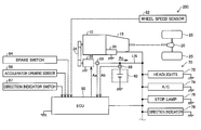
- FIG. 1 is a diagram illustrating the configuration of an automobile 200 according to an embodiment of the invention.
- the automobile 200 is a vehicle having idle reduction function.
- the automobile 200 includes an engine 10 , an automatic transmission 15 , a differential gear 20 , drive wheels 25 , a starter 30 , an alternator 35 , a battery 40 and an electronic control unit (ECU) 50 .
- ECU electronice control unit
- the engine 10 is an internal combustion engine that generates power by combustion of a fuel such as gasoline or light oil.
- the power of the engine 10 is transmitted to the automatic transmission 15 , while being transmitted to the alternator 35 via a drive mechanism 34 .
- the output of the engine 10 is changed by an engine control computer (not shown) according to the pressure of an accelerator pedal (not shown) stepped on by the driver.
- the automatic transmission 15 automatically changes the gear ratio (so-called gear shifting).
- the power (rotation speed ⁇ torque) of the engine 10 is subjected to gear shifting by the automatic transmission 15 and is transmitted as a desired rotation speed ⁇ torque via the differential gear 20 to the left and right drive wheels 25 .
- the power of the engine 10 is changed according to the accelerator pedal pressure and is transmitted via the automatic transmission 15 to the drive wheels 25 to accelerate or decelerate the vehicle (automobile 200 ).
- the alternator 35 is a generator configured to generate electric power using part of the power of the engine 10 .
- the generated electric power is used to charge the battery 40 via an inverter (not shown).
- power generation by the alternator 35 using the power of the engine 10 is called “fuel power generation”.
- the alternator 35 corresponds to the “generator” described in [Solution to Problem].
- the drive mechanism 34 serves to transmit the power of the engine 10 to the alternator 35 .
- the belt drive configuration is employed for the drive mechanism 34 .
- the battery 40 is a secondary battery of lead acid cells and serves as a DC power supply of a voltage of 14 V.
- the battery 40 supplies electric power to peripheral devices provided other than the engine main body.
- the peripheral devices provided other than the engine main body and operated with electric power of the battery 40 are called “auxiliary machines”.
- the group of auxiliary machines is called “auxiliary machinery”.
- the automobile 200 includes, for example, head lights 72 , an air conditioner (A/C) 74 , a stop lamp 76 and a direction indicator 78 as the auxiliary machinery 70 .
- the auxiliary machinery 70 include the starter 30 described above.
- the starter 30 is a device configured to start the engine 10 using the electric power supplied from the battery 40 and includes a starter motor (not shown).
- a starter motor (not shown).
- the starter 30 is activated to start the engine 10 .
- This starter 30 is used to restart the engine 10 in the no idling state as described later.
- the no idling state means the engine stop state by idle reduction control.
- the ECU 50 includes a CPU that performs computer programs, a ROM that stores computer programs and others, a RAM that temporarily stores data and input/ output ports connected with, for example, various sensors, switches, actuators and lights.
- the sensors and switches connected with the ECU 50 include: a wheel speed sensor 82 that detects the rotation speed of the drive wheels 25 ; a brake switch 84 that detects depression or non-depression of a brake pedal (not shown): an accelerator opening sensor 86 that detects the operation amount of an accelerator pedal (not shown) as an accelerator opening; a battery current sensor 88 that detects the charge-discharge current of the battery 40 ; an alternator current sensor 89 that detects the output current of the alternator 35 ; and a direction indicator switch 87 that gives an instruction to operate a direction indicator.
- the actuators include the starter 30 and the alternator 35 .
- the ECU 50 receives the supply of electric power from the battery 40 .
- the ECU 50 controls the starter 30 and the alternator 35 based on signals from the various sensors and switches mentioned above and an engine control computer (not shown), so as to control engine stops and restarts (idle reduction control) and controls the SOC of the battery 40 .
- This ECU 50 is the vehicle control device directly involved in the invention.
- the ECU 50 also performs controls to light up the stop lamp 76 in response to the ON state of the brake switch 84 and flash the lamp of a direction indicator 78 in response to the ON state of the direction indicator switch 87 .
- FIG. 2 is a diagram illustrating the functional configuration of the ECU 50 .
- the ECU 50 includes an idle reduction controller 90 and an SOC controller 100 .
- the functions of the idle reduction controller 90 and the SOC controller 100 are actually implemented by the CPU included in the ECU 50 executing the computer programs stored in the ROM.
- the idle reduction controller 90 obtains a wheel speed Vh detected by the wheel speed sensor 82 and an accelerator opening Tp detected by the accelerator opening sensor 86 and outputs an instruction Ss to stop/start the engine 10 to the starter 30 . More specifically, the idle reduction controller 90 determines that an engine stop condition is satisfied and outputs an engine stop instruction Ss to the starter 30 , when the wheel speed Vh is reduced below a predetermined speed (for example, 10 km/h). The idle reduction controller 90 determines that an engine restart condition is satisfied and outputs an engine restart instruction Ss to the starter 30 , when depression of the accelerator pedal is subsequently detected based on the accelerator opening Tp.
- a predetermined speed for example, 10 km/h
- the idle reduction controller 90 stops the engine 10 when the engine stop condition is satisfied, and restarts the engine 10 when the engine restart condition is satisfied after the engine stop.
- the engine stop condition and the engine restart condition are not limited to those described above.
- the engine stop condition may be that the wheel speed Vh is fully reduced to 0 km/h
- the engine restart condition may be that the driver releases the brake pedal.
- the SOC controller 100 includes a target SOC estimator 110 , a battery SOC calculator 120 and a feedback controller 130 .
- the target SOC estimator 110 estimates an SOC expected to be used during a time period from an engine stop to an engine restart (hereinafter called “stop and start period”) by idle reduction control during vehicle running (for example, when the wheel speed Vh>0 km/h), as a target SOC (hereinafter also called “target SOC value”) C 1 .
- the target SOC estimator 110 corresponds to the “idle reduction capacity setting section” described in [Solution to Problem].
- the “SOC” herein is defined as a value obtained by dividing the electric charge remaining in the battery by the electric charge accumulated in the battery in the fully charged state.
- the battery SOC calculator 120 calculates a current SOC (hereinafter called “present SOC value”) C 2 of the battery 40 , based on charge-discharge current (called “battery current”) of the battery 40 detected by the battery current sensor 88 . More specifically, the battery SOC calculator 120 calculates the present SOC value C 2 by integrating the charge-discharge currents Ab with setting the charge currents of the battery 40 to positive values and setting the discharge currents of the battery 40 to negative values.
- the configuration of the battery current sensor 88 and the battery SOC calculator 120 corresponds to the “SOC detector” described in [Solution to Problem].
- the SOC detector is not necessarily limited to the configuration that makes a calculation based on the battery current detected by the battery current sensor 88 but may be configured to make a calculation based on, for example, a battery electrolytic solution specific gravity sensor, a cell voltage sensor or a battery terminal voltage sensor. Moreover, the SOC detector is not necessarily limited to the configuration that detects the electric charge remaining in the battery but may be configured to detect the state of charge using another parameter, for example, a chargeable amount.
- the feedback controller 130 calculates a difference by subtracting the present SOC value C 2 from the target SOC value C 1 during vehicle running and determines a voltage command value Sv that makes the calculated difference equal to a value 0 by feedback control.
- This voltage command value Sv indicates the amount of power to be generated by the alternator 35 and is sent to the alternator 35 .
- the present SOC value C 2 is controlled to the target SOC value C 1 by fuel power generation.
- the feedback controller 130 corresponds to the “remaining capacity controller” described in [Solution to Problem].
- the SOC controller 100 has a function called “battery control” and a function called “charge control”, in addition to the above functions, although not specifically illustrated.
- the following describes battery control.
- the battery or more specifically the lead acid battery of the embodiment has a predetermined available SOC range (operable SOC range) based on the need for prolonged life. Accordingly, the “battery control” is performed to increase the power of the engine 10 and thereby increase the SOC into the above SOC range when the SOC of the battery 40 becomes lower than a lower limit (for example, 60%) of this SOC range and to consume the SOC and thereby decrease the SOC into the above SOC range when the SOC exceeds an upper limit (for example, 90%) of the SOC range.
- the SOC becomes lower than the lower limit during an engine stop by idle reduction control, the engine is restarted to increase the SOC into the above SOC range by fuel power generation.
- the “charge control” is a control process that suppresses the battery from being charged by fuel power generation during normal running to save fuel consumption and charges the battery by regenerative power generation during deceleration running.
- the charge control is a known configuration and is thus not specifically described here, but basically performs the following operations.
- feedback control by the feedback controller 130 during normal running is performed when the target SOC value C 1 is greater than the present SOC value C 2 ; a specified power generation cutoff voltage is set to the voltage command value Sv, which is given to the alternator 35 , when the target SOC value C 1 is equal to or less than the present SOC value C 2 .
- This configuration suppresses charging during normal running and saves fuel consumption.
- the “normal running” herein denotes the state of the automobile 200 other than “vehicle stop” when the vehicle speed is 0 km/h and “deceleration running” when the regenerative power generation described above is performed.
- the target SOC estimator 110 includes a driving environment predictor 112 , a vehicle state predictor 114 , an SOC distribution request level calculator 116 and a target SOC calculator 118 .
- the driving environment predictor 112 predicts the driving environment.
- the “driving environment” herein is a parameter indicating the extent that the vehicle falls in idle reduction state in the future (from now) and, in other words, a parameter regarding the ratio of a stop and start period in a future predetermined period.
- the “driving environment” accordingly means the driving environment of the vehicle that causes a vehicle stop by idle reduction control.
- the driving environment predictor 112 calculates a driving environmental index, which indicates the driving environment by an index, based on a wheel speed Vh detected by the wheel speed sensor 82 .
- the driving environment predictor 112 calculates a ratio R of vehicle stop time in a last predetermined period (for example, in last 10 minutes) going back from the present based on the wheel speed Vh and calculates a driving environment index P 1 from this calculated ratio R.
- a concrete procedure counts the total vehicle stop time when the wheel speed Vh is equal to a value 0 in a predetermined period, divides the total vehicle stop time by the total time of the predetermined period to calculate the ratio R and calculates the driving environment index P 1 from the ratio R.
- the high ratio R indicates a high frequency of vehicle stops and a long vehicle stop time and thereby leads to prediction of a high frequency of future vehicle stops and a long future vehicle stop time.
- This embodiment accordingly determines the driving environment index P 1 as follows:
- the driving environment index P 1 is set to a value 1;
- the driving environment index P 1 is set to a value 2;
- the driving environment index P 1 is set to a value 3;
- the driving environment index P 1 is set to a value 4.
- the above reference values 38%, 42% and 46% are not restrictive but may be replaced with other numerical values.
- the settings of the driving environment index P 1 are not limited to the four values 1 to 4 but may be any other suitable number of values, for example, three values, five values or six values.
- the suburban area has the lower driving environment index P 1
- the urban area has the higher driving environment index P 1 , so that the higher driving environment index P 1 indicates the higher degree of urbanization.
- the embodiment determines the driving environment index P 1 based on the wheel speed Vh detected by the wheel speed sensor 82 , but the invention is not limited to this configuration.
- the driving environment index P 1 may be determined, based on an average value of vehicle speed detected by a vehicle speed sensor, a variation in wheel speed Vh (acceleration) detected by the wheel speed sensor 82 , a gear position of a manual transmission in an MT (manual transmission) vehicle or a gear ratio of an automatic transmission in an AT (automatic transmission) vehicle.
- the lower average value of the vehicle speed indicates the higher degree of urbanization, so that the higher value is set to the driving environment index P 1 at the lower average value of vehicle speed.
- the higher variation in wheel speed Vh indicates the higher degree of urbanization, so that the higher value is set to the driving environment index P 1 at the higher variation in wheel speed Vh.
- the higher frequency of shift in gear position of the manual transmission indicates the higher degree of urbanization, so that the higher value is set to the driving environment index P 1 at the higher frequency of shift in gear position of the manual transmission.
- the higher frequency of change in gear ratio of the automatic transmission indicates the higher degree of urbanization, so that the higher value is set to the driving environment index P 1 at the higher frequency of change in gear ratio of the automatic transmission.
- the driving environment index P 1 may not be necessarily determined based on only one parameter selected among the wheel speed Vh and the respective parameters in place of the wheel speed Vh described above, but may be determined based on two or more of these parameters. In the application using two or more parameters, it is preferable to determine the driving environment index P 1 by multiplying the respective parameters by individual weighting factors. Using the wheel speed Vh and the respective parameters in place of the wheel speed Vh described above enables the driving environment to be predicted only in the autonomous system, i.e., the automobile 200 . Alternatively the driving environment index P 1 may be determined, based on information obtained from outside of the autonomous system. The information obtained from outside of the autonomous system is, for example, road map information of the navigation system. This application may identify whether a future driving area is an urban area or a suburban area based on the road map information of the navigation system and determine the driving environment index P 1 .
- the vehicle state predictor 114 predicts the state of the automobile 200 (vehicle state).
- the “vehicle state” herein is a parameter indicating how much SOC the automobile 200 is expected to consume hereafter. More specifically, the vehicle state predictor 114 calculates the amount of electric power consumed by the auxiliary machinery 70 based on an alternator current value Aa detected by the alternator current sensor 89 , the battery current value Ab detected by the battery current sensor 88 , and outputs the calculated amount of electric power as a vehicle state P 2 .
- the SOC consumption rate increases with an increase in amount of electric power consumed by the auxiliary machinery 70 .
- the vehicle state predictor 114 thus predicts the amount of electric power consumed by the auxiliary machinery 70 as the vehicle state P 2 .
- the detailed procedure of calculating the amount of electric power consumed by the own vehicle will be described in Chapter D.
- the driving environment predictor 112 and the vehicle state predictor 114 of the above configuration continually perform the predictions after the automobile 200 starts operation.
- the respective components 122 to 124 are actually implemented by the CPU included in the ECU 50 executing the computer programs stored in the ROM.
- the driving environment index P 1 predicted by the driving environment predictor 112 and the vehicle state P 2 predicted by the vehicle state predictor 114 are sent to an SOC distribution request level calculator 116 .
- the SOC distribution request level calculator 116 calculates an SOC distribution request level P 3 based on the driving environment index P 1 and the vehicle state P 2 .
- the target SOC calculator 118 calculates a target SOC value C 1 based on the SOC distribution request level P 3 .
- FIG. 3 is a flowchart showing a target SOC estimation routine.
- This target SOC estimation routine is performed repeatedly at predetermined time intervals (for example, 60 sec) during vehicle running. In other words, the target SOC estimation routine is not performed during a stop of the engine 10 by idle reduction control.
- the CPU of the ECU 50 obtains the driving environment index P 1 predicted by the driving environment predictor 112 ( FIG. 2 ) (step S 100 ) and also obtains the vehicle state P 2 predicted by the vehicle state predictor 114 ( FIG. 2 ) (step S 200 ).
- step S 300 the CPU calculates an SOC distribution request level based on the driving environment index P 1 and the vehicle state P 2 by using an SOC distribution request level calculation map MP (step S 300 ).
- the available SOC range is set for each type of battery as described above.
- the procedure of the embodiment distributes the available SOC range into an SOC range for idle reduction and an SOC range for charge control.
- the “SOC distribution request level” herein is a parameter specifying the level of the above distribution.
- FIG. 4 is a diagram illustrating the SOC distribution request level calculation map MP.
- the SOC distribution request level calculation map MP has the driving environment index P 1 as abscissa and the vehicle state P 2 as ordinate and stores map data to map the SOC distribution request level P 3 related to the value on the abscissa and the value on the ordinate.
- the SOC distribution request level calculation map MP is created by determining the relationship of the SOC distribution request level P 3 to the driving environment index P 1 and the vehicle state P 2 in advance experimentally or by simulation and is stored in the ROM.
- step S 300 reads the SOC distribution request level calculation map MP from the ROM and refers to this map MP to obtain the SOC distribution request level P 3 related to the driving environment index P 1 obtained at step S 100 and the vehicle state P 2 obtained at step S 200 .
- four value, A, B, C and D are provided as the SOC distribution request level P 3 .
- the values descend in the order of D, C, B and A.
- the SOC distribution request level P 3 increases with an increase in the driving environment index P 1 .
- the SOC distribution request level P 3 increases with an increase in the vehicle state P 2 .
- step S 400 the CPU calculates the target SOC value C 1 based on the SOC distribution request level P 3 by using a target SOC calculation table TB (step S 400 ).
- FIG. 5 is a diagram illustrating the target SOC calculation table TB.
- the target SOC calculation table TB has the SOC distribution request level P 3 as abscissa and the target SOC value C 1 as ordinate and shows the relationship of the target SOC value C 1 to the SOC distribution request level P 3 by a linear line L.
- the target SOC calculation table TB is created by determining the relationship of the target SOC value C 1 to the SOC distribution request level P 3 in advance experimentally or by simulation and is stored in the ROM.
- the process of step S 400 reads the target SOC calculation table TB from the ROM and refers to this table TB to obtain the target SOC value C 1 related to the SOC distribution request level P 3 calculated at step S 300 .
- the target SOC value C 1 shown by the linear line L is a value set in an available SOC range W of the battery 40 and indicates a distribution rate when the available SOC range W is distributed into a capacity for charge control and a capacity for idle reduction. More specifically, the area of the capacity for idle reduction is set on the lower side of the available SOC range W of the battery 40 , and the area of the capacity for charge control is set on the upper side. The boundary between these two areas shows the target SOC value C 1 . In other words, the level determined by adding the capacity for idle reduction to the lower limit of the available SOC range W is set as the target SOC value C 1 .
- the capacity for charge control is a battery capacity required due to suppression of fuel power generation by the charge control described above.
- the capacity for idle reduction is a capacity expected to be used in the future stop and start period. According to this embodiment, the capacity for idle reduction is set to an expected maximum capacity.
- the capacity for idle reduction increases with an increase in SOC distribution request level P 3 .
- the SOC is controlled to the upper side of the linear line L, the remaining capacity corresponding to the SOC in the available SOC range exceeds the capacity for idle reduction. This causes the idle reduction control to be fully implemented and further has an excess corresponding to the exceeding capacity.
- the target SOC value C 1 shown by the linear line L accordingly indicates the SOC that enables idle reduction control to be fully implemented hereafter and minimizes the amount of power generation for accumulation of SOC.
- the target SOC value C 1 linearly increases with an increase in SOC distribution request level P 3 as shown by the linear line L.
- the invention is, however, not limited to this example.
- the target SOC value C 1 may be configured to linearly increase with an increase in SOC distribution request level P 3 when the SOC distribution request level P 3 is equal to or less than a predetermined value and to maintain a fixed value when the SOC distribution request level P 3 is greater than the predetermined value. This configuration is effective for a battery having a relatively narrow available SOC range.
- a change in target SOC value C 1 may be shown by a curved line, instead of the linear line.
- the CPU outputs the target SOC value C 1 calculated at step S 400 to the feedback controller 130 (step S 500 ) and subsequently terminates the target SOC estimation routine.
- the feedback controller 130 ( FIG. 2 ) controls the present SOC value C 2 to the calculated target SOC value C 1 .
- the present SOC value C 2 indicates the remaining capacity in the available SOC range of the battery 40 . The control described above results in avoiding the remaining capacity from becoming less than the capacity for idle reduction during vehicle running. More specifically, when the present SOC value is located in the area of the capacity for charge control in FIG.
- charge control is performed to suppress the battery 40 from being charged by fuel power generation.
- the SOC decreases and is becoming less than the capacity for idle reduction, the SOC is controlled to the target SOC value C 1 shown by the linear line L by fuel power generation. Such control accordingly prevents the SOC from becoming less than the capacity for idle reduction.
- FIG. 6 is a diagram illustrating time charts of vehicle speed and SOC (present SOC value C 2 ) of the battery 40 during operation of the automobile 200 .
- the time charts have the vehicle speed and the SOC as the ordinate and the time as the abscissa.
- the vehicle speed gradually increases to normal running.
- the vehicle then shifts to the deceleration state at a time t 1 .
- the SOC gradually decreases as shown by the solid line.
- This solid line indicates a change according to the prior art, and this embodiment has a change as shown by the two-dot chain line. This is described below.
- the SOC gradually increases as shown by the solid line by regenerative power generation during deceleration.
- a period from the time t 2 (more specifically, at the time when the engine stop condition is satisfied) to a time t 3 when the vehicle speed has a rise is a stop and start period SST, when the engine 10 is at stop.
- the SOC gradually decreases by power consumption of the auxiliary machinery.
- the solid line when the SOC decreases to a lower limit SL during this engine stop (time tb), battery control is performed to restart the engine 10 . After the engine restart, the SOC increases by power generation using the power of the engine 10 , as shown by the solid line.
- the SOC when the SOC decreases during normal running and causes the remaining capacity in the available SOC range of the battery 40 to become less than the capacity for idle reduction (time ta), the SOC is increased by fuel power generation. As shown by the two-dot chain line in illustration, the SOC increases in a ta-t 2 period. This increase is in view of the maximum battery capacity expected to be used in the future stop and start period, so that the SOC decreasing in the stop and start period t 2 -t 3 does not reach the lower limit SL.
- the “future stop and start period” is not limited to one stop and start period SST as illustrated but includes all a plurality of stop and start periods within a predetermined time period.
- the engine 10 is restarted in the state that the SOC does not decrease to the lower limit in the stop and start period t 2 -t 3 , unlike the prior art.
- the following describes the vehicle state predictor 114 in detail.
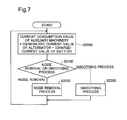
- FIG. 7 is a flowchart of calculating the electric current of auxiliary machinery corresponding to the vehicle state P 2 .
- This embodiment computes the vehicle state P 2 using not an observed value of electric current flowing in the auxiliary machinery 70 (hereinafter called “electric current of the auxiliary machinery 70 ”) but a calculated value of electric current flowing in the auxiliary machinery 70 .
- the observed value may include a value of instantaneous high current such as cracking current.
- the cracking current means high current flowing instantaneously.
- the cracking current is, for example, high current consumed by the starter 30 at a start or at a restart of the engine 10 . It is preferable to exclude such high current from the condition of calculation of the electric current flowing in the auxiliary machinery 70 .
- the vehicle state predictor 114 calculates the electric current of the auxiliary machinery 70 using the generated current value Aa of the alternator detected by the alternator current sensor 89 and the charge current value Ab of the battery detected by the battery current sensor 88 , calculates the amount of electric power to be consumed by the auxiliary machinery and outputs the calculated amount of electric power as the vehicle state P 2 .
- the vehicle state predictor 114 includes the cracking current for calculation of the amount of electric power to be consumed by the auxiliary machinery 70 and outputs the calculated amount of electric power as the vehicle state P 2 .
- the SOC controller 100 controls the generated voltage of the alternator 35 based on the magnitude of cracking current. This may result in increasing the amount of power generation of the alternator 35 and worsens the fuel consumption.
- FIG. 8 is a graph showing a variation in battery discharge current at a restart of the engine.
- a fixed amount of electric current is consumed by the auxiliary machinery 70 .
- the starter 30 is stated up to consume high current.
- the alternator 35 is not driven to generate electric power, so that the electric current consumed by the starter 30 is only the discharge current from the battery 40 .
- the discharge current of the battery 40 is high current exceeding 160 A. This high current works as cracking current.
- the discharge time of the cracking current is as short as 0.5 to 0.6 seconds.
- the alternator 35 is driven via the drive mechanism 34 to generate electric power. This decreases the discharge current of the battery 40 or causes the battery 40 to be charged by the alternator 35 .
- the vehicle state predictor 114 excludes the cracking current from the condition of computation of the vehicle state P 2 as described below.
- the vehicle state predictor 114 obtains an observed value of electric current of the auxiliary machinery 70 .
- the electric current is generated by the alternator 35 , and a part of the generated electric current is charged into the battery 40 while a remaining part is supplied to the auxiliary machinery 70 .
- the observed value of electric current of the auxiliary machinery 70 is obtained by subtracting the electric current to be charged into the battery 40 from the electric current generated by the alternator 35 .
- the electric current of the auxiliary machinery 70 is larger than the electric current generated by the alternator 35 , electric current is supplied from the battery 40 to the auxiliary machinery 70 . In this case, the battery 40 is discharged. Discharging may be regarded as charging of electric current of negative magnitude. Accordingly, the electric current of the auxiliary machinery 70 is measurable similarly in this case.
- the vehicle state predictor 114 determines whether instantaneous large noise such as cracking current is to be removed or smoothing process is to be performed for calculation of the electric current of the auxiliary machinery 70 .
- the vehicle state predictor 114 performs the noise removal process at step S 2200 and the smoothing process at step S 2300 . The details of the noise removal process and the smoothing process will be described later.
- the electric current of the auxiliary machinery 70 after the noise removal process or the electric current of the auxiliary machinery 70 after the smoothing process is referred to as “calculated value of electric current of the auxiliary machinery 70 ”.
- the calculated value of electric current of the auxiliary machinery 70 is used as a control condition of the generated voltage of the alternator 35 .
- the amount of electric power to be consumed by the auxiliary machinery 70 is calculated from the calculated value of electric current of the auxiliary machinery 70 .
- the calculated amount of electric power is output as the vehicle state P 2 .
- High current is discharged from the battery 40 , for example, on the occasion of consumption of electric current by stop lamps, indicators, power windows, power steering or antilock braking, other than the start of the engine 10 by the starter 30 .
- electric current may be flowed for a relatively long time period, or high current may be flowed due to multiple factors. In such cases, electric current may be excessively discharged from the battery 40 without power generation by the alternator 35 .
- FIG. 9 is a control block diagram involved in the smoothing process.
- a first subtractor 1940 subtracts the charge current value Ab of the battery 40 from the generated current value Aa of the alternator 35 to calculate an observed value Ac of electric current of the auxiliary machinery 70 .
- the observed value Ac of electric current of the auxiliary machinery 70 denotes electric current actually consumed by the auxiliary machinery 70 .
- a second subtractor 1942 subtracts a previous calculated value Ae 0 of electric current of the auxiliary machinery 70 from the observed value Ac of electric current of the auxiliary machinery 70 to calculate a smoothened input current value Ac*.
- the smoothing process is repeated at predetermined intervals. The last operation in this series of smoothing process is performed by an adder 1946 as described below.
- a calculated value Ae of electric current of the auxiliary machinery 70 is output. In a next cycle, this calculated value Ae is used as the previous calculated value Ae 0 of electric current of the auxiliary machinery 70 .
- the smoothened input current value Ac* denotes a difference between the previous calculated value Ae 0 of electric current of the auxiliary machinery 70 and the observed value Ac of electric current of the auxiliary machinery 70 .
- a divider 1944 divides the smoothened input current value Ac* by a smoothing factor k to calculate 1/k of the difference between the previous calculated value Ae of electric current of the auxiliary machinery 70 and the observed value Ac of electric current of the auxiliary machinery 70 , as a smoothened output current value Ad.
- the value of the smoothing factor k is any value greater than 1.
- the calculated value Ae of electric current of the auxiliary machinery 70 is an average value of the observed value Ac of electric current of the auxiliary machinery 70 and the previous calculated value Ae 0 of electric current of the auxiliary machinery 70 .
- the smoothing factor may be an integral number m of not less than 2, and the calculated value Ae of electric current of the auxiliary machinery 70 may be a moving average of previous calculated values of electric current of the auxiliary machinery 70 in previous (m ⁇ 1) cycles and the observed value Ac of electric current of the auxiliary machinery 70 in a present cycle.
- the adder 1946 adds the smoothened output current value Ad calculated at step S 2120 to the previous calculated value Ae 0 of electric current of the auxiliary machinery 70 to obtain a calculated value Ae of electric current of the auxiliary machinery 70 .
- the calculated value Ae of electric current of the auxiliary machinery 70 is used as the previous calculated value Ae 0 of electric current of the auxiliary machinery 70 in a next cycle.
- the calculated value Ae of electric current of the auxiliary machinery 70 is also used for computation of the vehicle state P 2 .
- the calculated value Ae of electric current of the auxiliary machinery 70 becomes smaller than the previous calculated value Ae 0 of electric current of the auxiliary machinery 70 .
- the calculated value Ae of electric current of the auxiliary machinery 70 becomes larger than the previous calculated value Ae 0 of electric current of the auxiliary machinery 70 .
- FIG. 10 is a flowchart showing the processing of step S 2100 in FIG. 7 .
- the vehicle state predictor 114 determines whether a previous observed value ( ⁇ Ab) of discharge current of the battery 40 is not larger than a threshold value It and whether a present observed value ( ⁇ Ab) of discharge current of the battery 40 is larger than the threshold value It.
- the observed value of discharge current of the battery 40 is obtained by changing the sign of the charge current value of the battery 40 from positive to negative.
- the magnitude of the threshold value It is preferably larger than a value of power consumption of the battery 40 in the idle reduction state of the engine 10 but smaller than a current value at the start-up of the starter 30 and may be set in, for example, in the range of 95 A to 120 A.
- the vehicle state predictor 114 shifts the processing to step S 2120 to reset the value of a mask counter MC to zero.
- the vehicle state predictor 114 shifts the processing to step S 2230 to add 1 to the present value of the mask counter MC.
- the above two conditions are satisfied in the case of a state change from the state that the observed value ( ⁇ Ab) of discharge current of the battery 40 is not larger than the threshold value It to the state that the observed value ( ⁇ Ab) is larger than the threshold value It, i.e., in the case of generation of cracking current.
- the vehicle state predictor 114 determines whether the value of the mask counter MC is equal to or less than a predetermined reference value X. When the value of the mask counter MC is equal to or less than X, the vehicle state predictor 114 shifts the processing to step S 2200 (noise removal process).
- the noise removal process uses the previous calculated value Ae 0 of electric current of the auxiliary machinery 70 as the calculated value Ae of electric current of the auxiliary machinery 70 .
- the previous calculated value Ae 0 of electric current of the auxiliary machinery 70 is not affected by the present observed value ( ⁇ Ab) of discharge current of the battery 40 . Accordingly, the present observed value ( ⁇ Ab) of discharge current of the battery 4 is excluded as noise from the calculated value Ae of electric current of the auxiliary machinery 70 .
- step S 2140 When the value of the mask counter MC is larger than X at step S 2140 , on the other hand, the vehicle state predictor 114 shifts the processing to step S 2300 .
- step S 2300 the smoothing process described above is performed, so that the calculated value Ae of electric current of the auxiliary machinery 70 after the smoothing process is obtained.
- the details of the smoothing process are identical with those described above with reference to FIG. 9 .
- FIG. 11 is a diagram showing variations in discharge current of the battery 40 and in calculated value of electric current of the auxiliary machinery 70 according to this embodiment.
- FIG. 11A shows a case when the discharge current of the battery 40 increases smoothly
- FIG. 11B shows a case when the discharge current of the battery 40 increases abruptly.
- the value X used at step S 2230 in FIG. 10 is set equal to 5
- a time period for masking with the value of the mask counter MC (called “mask period”) is preferably set to a smaller value than the smoothing factor k used in the smoothing process.
- This embodiment uses the value of the mask counter MC for the determination of step S 2140 , but a timer may be used instead of the mask counter MC.
- the noise called cracking current is excluded from the condition of computation of the calculated value Ae of electric current of the auxiliary machinery 70 .
- FIG. 12 is a processing flowchart according to a comparative example.
- This comparative example performs a process of relieving the effect of high current without providing the mask period.
- the vehicle state predictor 114 determines whether the observed value ( ⁇ Ab) of discharge current of the battery 40 is larger than the threshold value It. When the observed value ( ⁇ Ab) of discharge current of the battery 40 is larger than the threshold value It, the vehicle state predictor 114 shifts the processing to step S 410 to use the previous calculated value Ae 0 of electric current of the auxiliary machinery 70 as the calculated value Ae of electric current of the auxiliary machinery 70 .
- This process is identical with the process of step S 2200 in FIG. 10 .
- step S 2420 When the observed value ( ⁇ Ab) of discharge current of the battery 40 is equal to or less than the threshold value It, on the other hand, the vehicle state predictor 114 shifts the processing to step S 2420 to perform the smoothing process. This process is identical with the process of step S 2300 in FIG. 10 .
- FIG. 13 is a diagram showing variations in battery current according to the comparative example.
- FIG. 13A shows a case when the discharge current of the battery 40 increases smoothly
- FIG. 13B shows a case when the discharge current of the battery 40 increases abruptly.
- the observed value ( ⁇ Ab) of discharge current of the battery 40 becomes larger than the threshold value It, the previous calculated value Ae 0 of electric current of the auxiliary machinery 70 is used as the calculated value Ae of electric current of the auxiliary machinery 70 .
- the calculated value Ae of electric current of the auxiliary machinery 70 immediately before the state that the observed value ( ⁇ Ab) of discharge current of the battery 40 becomes larger than the threshold value It is maintained as the calculated value Ae of electric current of the auxiliary machinery 70 , until the observed value ( ⁇ Ab) of discharge current of the battery 40 becomes equal to or less than the threshold value It. Accordingly, in the comparative example, the calculated value Ae of electric current of the auxiliary machinery 70 does not approach the observed value of discharge current of the battery 40 unless the observed value of discharge current of the battery 40 becomes equal to or less than the threshold value It. According to the embodiment shown in FIG.
- the calculated value Ae of electric current of the auxiliary machinery 70 approaches the observed value ( ⁇ Ab) of discharge current of the battery 40 after the end of the mask period.
- Providing the mask period like this embodiment in the process of relieving the effect of high current enables the calculated value Ae of electric current of the auxiliary machinery 70 to follow the observed value ( ⁇ Ab) of discharge current of the battery 40 after elapse of the mask period. This results in allowing for an increase in control voltage of the alternator 35 after elapse of the mask period, thus facilitating charging into the battery 40 .
- the mask period is preferably limited to a fixed time period.
- the automobile 200 of the embodiment does not restart the engine 10 in the state that the SOC decreases to the lower limit in the stop and start period t 2 -t 3 .
- An engine restart due to shortage of SOC in the middle of the stop and start period requires 3 times to even 5 times the amount of fuel required in the case of an increase in power during operation of the engine to increase the SOC.
- the fuel consumption effect per unit SOC for example, 1% SOC
- the automobile 200 of the embodiment accordingly improves the fuel consumption, compared with the prior art.
- the embodiment when the current value of auxiliary machinery 70 is instantaneously changed, the embodiment also suppresses the effect of the latest current value in the smoothing process. This effectively prevents the distribution ratio between the capacity for charge control and the capacity for idle reduction from being mistakenly specified due to the instantaneous large current.
- the cracking current works as the noise in calculation of electric current of the auxiliary machinery 70 .
- the embodiment uses the calculated value of discharge current of the battery 40 immediately before the occurrence of cracking current is used as the basis for control of the generated voltage of the alternator 35 for a predetermined time period. This reduces the effect of cracking current (effect of noise). In the case that high current is maintained (in the case other than cracking current), this embodiment enables the calculated value of discharge current of the battery 40 as the basis for control of the generated voltage of the alternator 35 to approach the observed value of discharge current of the battery 40 .
- the above embodiment is configured to determine the SOC distribution request level P 3 based on the driving environment index P 1 and the vehicle state P 2 and calculate the target SOC based on the SOC distribution request level P 3 .
- the configuration may be modified to directly calculate the target SOC, based on the driving environment index P 1 and the vehicle state P 2 .
- the configuration may be modified to directly calculate a distribution ratio of the available SOC range of the battery to the capacity for charge control and the capacity for idle reduction, based on the driving environment index P 1 and the vehicle state P 2 .
- the above embodiment calculates the SOC distribution request level based on both the driving environment index P 1 and the vehicle state P 2 .
- the configuration may be modified to calculate the SOC distribution request level based on only the vehicle state P 2 .
- the above embodiment describes the configuration of calculating the observed value Ac of electric current flowing through the wire connection LN-side (shown in FIG. 1 ), i.e., the current value of electric current flowing through the entire electronic equipment including the auxiliary machinery, based on the generated current value Aa of the alternator and the charge current value Ab (discharge current ( ⁇ Ab)) of the battery.
- the invention is, however, not limited to this configuration.
- a current sensor may be provided on the upstream side of the wire connection LN, and the current value may be obtained from this current sensor. Any configuration may be employed to obtain the current value of electric current flowing through the general electronics which are operated with electric power of the battery and include auxiliary machinery.
- the battery is a lead acid battery.
- the invention is, however, not limited to this type of battery but may be applied to any of various other types of batteries, such as lithium ion battery and rocking chair-type battery.
- the vehicle is an automobile.
- the invention may be applied to a vehicle other than automobile, such as train.
- Part of the functions configured by the software in the above embodiment may be configured by hardware (for example, integrated circuit), or part of the functions configured by the hardware may be configured by software.
- a modification may omit charge control which suppresses the battery from being charged during normal running to save the amount of fuel consumption and charges the battery by regenerative power generation during deceleration running.
Abstract
A charge control device for a battery is mounted on a vehicle, the vehicle comprises an engine, a generator driven with power of the engine, the battery configured to be chargeable with electric power generated by the generator, and auxiliary machinery operated with electric power of the battery. The charge control device comprises: a load condition detector that is configured to detect a load condition of the auxiliary machinery; and a charge controller that is configured to control charging into the battery, based on the load condition of the auxiliary machinery, wherein in response to detection of a state change from a state in which a magnitude of the load of the auxiliary machinery is smaller than a predetermined threshold value to a state in which a magnitude of the load is larger than the predetermined threshold value, the charge controller controls a generated voltage by the generator based on the magnitude of the load of the auxiliary machinery prior to the state change during a time period until a specified time has elapsed after the detection of the state change, and the charge controller controls a generated voltage by the generator based on a magnitude of the load of the auxiliary machinery detected by the load condition detector during a time period after elapse of the specified time.
Description
- The present invention relates to a charge control device for a battery mounted on a vehicle, a vehicle control device, a vehicle, a charge control method and a vehicle control method.
- An automobile has an engine and a battery, wherein the battery is charged with power of the engine. A known technique of charge control for charging the battery suppresses the battery from being charged during normal running to save the amount of fuel consumption, while allowing the battery to be charged by regenerative power generation during deceleration running.
- Idle reduction control is also known as the technology to save the amount of fuel consumption.
Patent Literature 1 given below discloses an automobile having both the function of charge control and the function of idle reduction control, in order to meet the requirement for improvement of fuel consumption. A known configuration of a charge control device increases the generated voltage of an alternator with an increase in consumed current of auxiliary machinery (for example, Patent Literature 4). - PTL 1: JP 2005-67293A
- PTL 2: JP 2011-163281A
- PTL 3: JP 2004-176624A
- PTL 4: JP 2007-230513A
- The above technique, however, may cause a restart of the engine with a decrease in SOC (state of charge), due to consumption of electricity accumulated in the battery by auxiliary machinery during an engine stop in idle reduction control. “SOC” is an index indicating how much electric power remains in the battery. In some cases, for example, during lighting of indicators or stop lamps or during operation of power steering or power windows, a large amount of electricity accumulated in the battery may be consumed. Controlling the power generation of the generator based on such high current causes an increase in fuel consumption. It is accordingly preferable to regard such consumption of high current as noise and exclude such high current from a control condition of power generation. Lighting of indicators or stop lamps may continue for a relatively long time. Completely excluding such high current as the noise from the control condition of power generation of the generator is, however, more likely to decrease the SOC of the battery. This is thus more likely to cause a restart of the engine during an engine stop in idle reduction control.
- In order to achieve at least part of the foregoing, the present invention provides various aspects described below.
- (1) According to one aspect of the invention, there is provided a charge control device for a battery mounted on a vehicle, the vehicle comprising an engine, a generator driven with power of the engine, the battery configured to be chargeable with electric power generated by the generator, and auxiliary machinery operated with electric power of the battery. The charge control device comprises: a load condition detector that is configured to detect a load condition of the auxiliary machinery; and a charge controller that is configured to control charging into the battery, based on the load condition of the auxiliary machinery, wherein in response to detection of a state change from a state in which a magnitude of the load of the auxiliary machinery is smaller than a predetermined threshold value to a state in which a magnitude of the load is larger than the predetermined threshold value, the charge controller controls a generated voltage by the generator based on the magnitude of the load of the auxiliary machinery prior to the state change during a time period until a specified time has elapsed after the detection of the state change, and the charge controller controls a generated voltage by the generator based on a magnitude of the load of the auxiliary machinery detected by the load condition detector during a time period after elapse of the specified time. In the charge control device according to this aspect, even in the case of an instantaneous state change from the state in which a load condition of the auxiliary machinery is smaller than the predetermined threshold value to the state in which a load condition of the auxiliary machinery is larger than the predetermined threshold value, this state change is excluded as noise during the time period until elapse of the specified time, and the generated voltage of the generator is controlled based on the load state of the auxiliary machinery prior to the state change. When the load condition of the auxiliary machinery indicates a steady increase in load that continues for a relatively longer time period than the specified time, the generated voltage of the generator is controlled based on the detected load condition.
- (2) The charge control device according to the aspect before, wherein the vehicle includes a starter configured to start the engine, and the threshold value may be a value that is larger than current consumption of the auxiliary machinery in an idle reduction state of the engine but may be smaller than current consumption of the starter. The charge control device according to this aspect enables the threshold value to be set to a smaller value than cracking current.
- (3) The charge control device according to the aspect before, wherein the charge controller may use an observed value of electric current of the auxiliary machinery to obtain a calculated value of electric current of the auxiliary machinery for controlling the generated voltage by the generator, and when obtaining the calculated value of electric current of the auxiliary machinery, the charge controller may perform a smoothing process that reduces a variation in the calculated value of electric current of the auxiliary machinery to be smaller than a variation in the observed value of electric current of the auxiliary machinery. The charge control device according to this aspect performs the smoothing process when obtaining the calculated value of electric current of the auxiliary machinery, thus enabling the calculated value of electric current of the auxiliary machinery to moderately follow the observed value of electric current of the auxiliary machinery.
- (4) According to one aspect of the invention, there is provided a vehicle control device mounted on a vehicle, the vehicle comprising an engine, a generator driven with power of the engine, a battery configured to be chargeable with electric power generated by the generator, and auxiliary machinery operated with electric power of the battery. The vehicle control device may comprise the charge control device according to any one of the aspects before; an idle reduction controller that is configured to perform idle reduction control of the engine; and an SOC detector that is configured to detect a state of charge (SOC) of the battery. The charge control device may further comprise an idle reduction capacity setter that is configured to set, during running of the vehicle, a capacity for idle reduction in an available SOC range of the battery, based on the current value, wherein the capacity for idle reduction is expected to be used in a stop and start period from an engine stop to an engine restart by the idle reduction control; and a remaining capacity controller that is configured to control an amount of power generation by the generator so as to avoid a remaining capacity in the available SOC range, which corresponds to the SOC detected by the SOC detector, from becoming smaller than the capacity for idle reduction during running of the vehicle. In the vehicle control device according to this aspect, the amount of power generation by the generator is controlled during running of the vehicle, such as to avoid the remaining capacity in the available SOC range of the battery from becoming smaller than the capacity for idle reduction, which is expected to be used in the stop and start period. This suppresses a restart of the engine due to the insufficient SOC in the middle of the stop and start period. An increase in SOC with an increase in power during operation of the engine has the higher effect on fuel consumption per unit SOC (for example, 1% SOC), compared with a restart of the engine due to the insufficient SOC in the middle of the stop and start period. This accordingly improves the fuel consumption of the vehicle. Additionally, even in the case of an instantaneous state change from the state in which a load condition of the auxiliary machinery is smaller than the predetermined threshold value to the state in which a load condition of the auxiliary machinery is larger than the predetermined threshold value, this state change is excluded as noise during the time period until elapse of the specified time, and the generated voltage of the generator is controlled based on the load state of the auxiliary machinery prior to the state change. When the load condition of the auxiliary machinery indicates a steady increase in load that continues for a relatively longer time period than the specified time, the generated voltage of the generator is controlled based on the detected load condition.
- (5) According to one aspect of the invention, there is provided a vehicle. This vehicle may comprise an engine; a battery that is configured to be chargeable with electric power generated by a generator that is driven with power of the engine; auxiliary machinery that is operated with electric power of the battery; and the vehicle control device according to the aspect before.
- (6) According to one aspect of the invention, there is provided a charge control method for a battery mounted on a vehicle, the vehicle comprising an engine, a generator driven with power of the engine, the battery configured to be chargeable with electric power generated by the generator, and auxiliary machinery operated with electric power of the battery. The charge control method may comprise the steps of: (a) detecting magnitude of a load of the auxiliary machinery; (b) determining whether there is a state change from a state in which a magnitude of the load of the auxiliary machinery is smaller than a predetermined threshold value to a state in which a magnitude of the load is larger than the predetermined threshold value; and (c) controlling charging into the battery based on the magnitude of the load of the auxiliary machinery. In response to detection of the state change from the state in which a magnitude of the load of the auxiliary machinery is smaller than the predetermined threshold value to the state in which a magnitude of the load is larger than the predetermined threshold value in the step (b), in the step (c), a generated voltage by the generator is controlled based on the magnitude of the load of the auxiliary machinery prior to the state change during a time period until a specified time has elapsed after the detection of the state change, while a generated voltage by the generator is controlled based on the detected magnitude of the load of the auxiliary machinery during a time period after elapse of the specified time.
- (7) According to one aspect of the invention, there is provided a vehicle control method of controlling a vehicle, the vehicle comprising an engine, a generator driven with power of the engine, a battery configured to be chargeable with electric power generated by the generator, and auxiliary machinery operated with electric power of the battery. In addition to the steps of the charge control method according to the aspect before, the vehicle control method may comprise the steps of (d) performing idle reduction control; (e) detecting a state of charge (SO C) of the battery; (f) measuring a current value of electric current flowing through the auxiliary machinery; (g) obtaining a calculated value of electric current of the auxiliary machinery by performing a smoothing process that reduces a variation in calculated value of electric current of the auxiliary machinery to be smaller than a variation in observed value of electric current of the auxiliary machinery; and (h) setting, during running of the vehicle, a capacity for idle reduction in an available SOC range of the battery, based on a current value corrected in the step (g), wherein the capacity for idle reduction is expected to be used in a stop and start period from an engine stop to an engine restart by the idle reduction control, wherein in the step (c), an amount of power generation by the generator is further controlled so as to avoid a remaining capacity in the available SOC range, which corresponds to the SOC detected by the SOC detector, from becoming smaller than the capacity for idle reduction during running of the vehicle.
- The invention may be implemented by a variety of aspects other than the charge control device for battery, for example, a vehicle control device, a vehicle, a charge control method and a vehicle control method.
-
FIG. 1 is a diagram illustrating the configuration of an automobile according to an embodiment of the invention. -
FIG. 2 is a diagram illustrating the functional configuration of the ECU. -
FIG. 3 is a flowchart showing a target SOC estimation routine. -
FIG. 4 is a diagram illustrating the SOC distribution request level calculation map MP. -
FIG. 5 is a diagram illustrating the target SOC calculation table TB. -
FIG. 6 is a diagram illustrating time charts of vehicle speed and SOC (present SOC value C2) of the battery during operation of the automobile. -
FIG. 7 is a flowchart of calculating the electric current of auxiliary machinery corresponding to the vehicle state P2. -
FIG. 8 is a graph showing a variation in battery discharge current at a restart of the engine. -
FIG. 9 is a control block diagram involved in the smoothing process. -
FIG. 10 is a flowchart showing the processing of step S2100 inFIG. 7 . -
FIG. 11 is a diagram showing variations in discharge current of the battery and in calculated value of electric current of the auxiliary machinery according to this embodiment. -
FIG. 12 is a processing flowchart according to a comparative example. -
FIG. 13 is a diagram showing variations in battery current according to the comparative example. - Some aspects of the invention are described below with reference to embodiments in the following sequence:
- A. General Configuration
- B. Configuration of ECU
- C. Configuration of Target SOC Estimator
- D. Configuration of Vehicle State Predictor
- E. Functions and Advantageous Effects
- F. Modifications
-
FIG. 1 is a diagram illustrating the configuration of anautomobile 200 according to an embodiment of the invention. Theautomobile 200 is a vehicle having idle reduction function. Theautomobile 200 includes anengine 10, anautomatic transmission 15, adifferential gear 20,drive wheels 25, astarter 30, analternator 35, abattery 40 and an electronic control unit (ECU) 50. - The
engine 10 is an internal combustion engine that generates power by combustion of a fuel such as gasoline or light oil. The power of theengine 10 is transmitted to theautomatic transmission 15, while being transmitted to thealternator 35 via adrive mechanism 34. The output of theengine 10 is changed by an engine control computer (not shown) according to the pressure of an accelerator pedal (not shown) stepped on by the driver. - The
automatic transmission 15 automatically changes the gear ratio (so-called gear shifting). The power (rotation speed·torque) of theengine 10 is subjected to gear shifting by theautomatic transmission 15 and is transmitted as a desired rotation speed·torque via thedifferential gear 20 to the left andright drive wheels 25. The power of theengine 10 is changed according to the accelerator pedal pressure and is transmitted via theautomatic transmission 15 to thedrive wheels 25 to accelerate or decelerate the vehicle (automobile 200). - The
alternator 35 is a generator configured to generate electric power using part of the power of theengine 10. The generated electric power is used to charge thebattery 40 via an inverter (not shown). In the description hereof, power generation by thealternator 35 using the power of theengine 10 is called “fuel power generation”. Thealternator 35 corresponds to the “generator” described in [Solution to Problem]. Thedrive mechanism 34 serves to transmit the power of theengine 10 to thealternator 35. According to this embodiment, the belt drive configuration is employed for thedrive mechanism 34. - The
battery 40 is a secondary battery of lead acid cells and serves as a DC power supply of a voltage of 14 V. Thebattery 40 supplies electric power to peripheral devices provided other than the engine main body. In the description hereof, the peripheral devices provided other than the engine main body and operated with electric power of thebattery 40 are called “auxiliary machines”. The group of auxiliary machines is called “auxiliary machinery”. Theautomobile 200 includes, for example, head lights 72, an air conditioner (A/C) 74, astop lamp 76 and adirection indicator 78 as theauxiliary machinery 70. Theauxiliary machinery 70 include thestarter 30 described above. - The
starter 30 is a device configured to start theengine 10 using the electric power supplied from thebattery 40 and includes a starter motor (not shown). In general, when the driver operates an ignition switch (not shown) to start driving an automobile at a stop, thestarter 30 is activated to start theengine 10. Thisstarter 30 is used to restart theengine 10 in the no idling state as described later. In the description hereof, the no idling state means the engine stop state by idle reduction control. When thestarter 30 is operated, instantaneous high current called cracking current is generated. - The
ECU 50 includes a CPU that performs computer programs, a ROM that stores computer programs and others, a RAM that temporarily stores data and input/ output ports connected with, for example, various sensors, switches, actuators and lights. The sensors and switches connected with theECU 50 include: awheel speed sensor 82 that detects the rotation speed of thedrive wheels 25; abrake switch 84 that detects depression or non-depression of a brake pedal (not shown): anaccelerator opening sensor 86 that detects the operation amount of an accelerator pedal (not shown) as an accelerator opening; abattery current sensor 88 that detects the charge-discharge current of thebattery 40; an alternatorcurrent sensor 89 that detects the output current of thealternator 35; and adirection indicator switch 87 that gives an instruction to operate a direction indicator. The actuators include thestarter 30 and thealternator 35. TheECU 50 receives the supply of electric power from thebattery 40. - The
ECU 50 controls thestarter 30 and thealternator 35 based on signals from the various sensors and switches mentioned above and an engine control computer (not shown), so as to control engine stops and restarts (idle reduction control) and controls the SOC of thebattery 40. ThisECU 50 is the vehicle control device directly involved in the invention. TheECU 50 also performs controls to light up thestop lamp 76 in response to the ON state of thebrake switch 84 and flash the lamp of adirection indicator 78 in response to the ON state of thedirection indicator switch 87. -
FIG. 2 is a diagram illustrating the functional configuration of theECU 50. As illustrated, theECU 50 includes anidle reduction controller 90 and anSOC controller 100. The functions of theidle reduction controller 90 and theSOC controller 100 are actually implemented by the CPU included in theECU 50 executing the computer programs stored in the ROM. - The
idle reduction controller 90 obtains a wheel speed Vh detected by thewheel speed sensor 82 and an accelerator opening Tp detected by theaccelerator opening sensor 86 and outputs an instruction Ss to stop/start theengine 10 to thestarter 30. More specifically, theidle reduction controller 90 determines that an engine stop condition is satisfied and outputs an engine stop instruction Ss to thestarter 30, when the wheel speed Vh is reduced below a predetermined speed (for example, 10 km/h). Theidle reduction controller 90 determines that an engine restart condition is satisfied and outputs an engine restart instruction Ss to thestarter 30, when depression of the accelerator pedal is subsequently detected based on the accelerator opening Tp. - In other words, the
idle reduction controller 90 stops theengine 10 when the engine stop condition is satisfied, and restarts theengine 10 when the engine restart condition is satisfied after the engine stop. The engine stop condition and the engine restart condition are not limited to those described above. For example, the engine stop condition may be that the wheel speed Vh is fully reduced to 0 km/h, and the engine restart condition may be that the driver releases the brake pedal. - The
SOC controller 100 includes atarget SOC estimator 110, abattery SOC calculator 120 and afeedback controller 130. Thetarget SOC estimator 110 estimates an SOC expected to be used during a time period from an engine stop to an engine restart (hereinafter called “stop and start period”) by idle reduction control during vehicle running (for example, when the wheel speed Vh>0 km/h), as a target SOC (hereinafter also called “target SOC value”) C1. The detailed configuration will be described in Chapter C. Thetarget SOC estimator 110 corresponds to the “idle reduction capacity setting section” described in [Solution to Problem]. The “SOC” herein is defined as a value obtained by dividing the electric charge remaining in the battery by the electric charge accumulated in the battery in the fully charged state. - The
battery SOC calculator 120 calculates a current SOC (hereinafter called “present SOC value”) C2 of thebattery 40, based on charge-discharge current (called “battery current”) of thebattery 40 detected by thebattery current sensor 88. More specifically, thebattery SOC calculator 120 calculates the present SOC value C2 by integrating the charge-discharge currents Ab with setting the charge currents of thebattery 40 to positive values and setting the discharge currents of thebattery 40 to negative values. The configuration of thebattery current sensor 88 and thebattery SOC calculator 120 corresponds to the “SOC detector” described in [Solution to Problem]. The SOC detector is not necessarily limited to the configuration that makes a calculation based on the battery current detected by thebattery current sensor 88 but may be configured to make a calculation based on, for example, a battery electrolytic solution specific gravity sensor, a cell voltage sensor or a battery terminal voltage sensor. Moreover, the SOC detector is not necessarily limited to the configuration that detects the electric charge remaining in the battery but may be configured to detect the state of charge using another parameter, for example, a chargeable amount. - The
feedback controller 130 calculates a difference by subtracting the present SOC value C2 from the target SOC value C1 during vehicle running and determines a voltage command value Sv that makes the calculated difference equal to avalue 0 by feedback control. This voltage command value Sv indicates the amount of power to be generated by thealternator 35 and is sent to thealternator 35. As a result, the present SOC value C2 is controlled to the target SOC value C1 by fuel power generation. Thefeedback controller 130 corresponds to the “remaining capacity controller” described in [Solution to Problem]. - The
SOC controller 100 has a function called “battery control” and a function called “charge control”, in addition to the above functions, although not specifically illustrated. The following describes battery control. The battery or more specifically the lead acid battery of the embodiment has a predetermined available SOC range (operable SOC range) based on the need for prolonged life. Accordingly, the “battery control” is performed to increase the power of theengine 10 and thereby increase the SOC into the above SOC range when the SOC of thebattery 40 becomes lower than a lower limit (for example, 60%) of this SOC range and to consume the SOC and thereby decrease the SOC into the above SOC range when the SOC exceeds an upper limit (for example, 90%) of the SOC range. When the SOC becomes lower than the lower limit during an engine stop by idle reduction control, the engine is restarted to increase the SOC into the above SOC range by fuel power generation. - The “charge control” is a control process that suppresses the battery from being charged by fuel power generation during normal running to save fuel consumption and charges the battery by regenerative power generation during deceleration running. The charge control is a known configuration and is thus not specifically described here, but basically performs the following operations. In the charge control, feedback control by the
feedback controller 130 during normal running is performed when the target SOC value C1 is greater than the present SOC value C2; a specified power generation cutoff voltage is set to the voltage command value Sv, which is given to thealternator 35, when the target SOC value C1 is equal to or less than the present SOC value C2. This configuration suppresses charging during normal running and saves fuel consumption. The “normal running” herein denotes the state of theautomobile 200 other than “vehicle stop” when the vehicle speed is 0 km/h and “deceleration running” when the regenerative power generation described above is performed. - The
target SOC estimator 110 includes a drivingenvironment predictor 112, avehicle state predictor 114, an SOC distributionrequest level calculator 116 and atarget SOC calculator 118. - The driving
environment predictor 112 predicts the driving environment. The “driving environment” herein is a parameter indicating the extent that the vehicle falls in idle reduction state in the future (from now) and, in other words, a parameter regarding the ratio of a stop and start period in a future predetermined period. The “driving environment” accordingly means the driving environment of the vehicle that causes a vehicle stop by idle reduction control. The drivingenvironment predictor 112 calculates a driving environmental index, which indicates the driving environment by an index, based on a wheel speed Vh detected by thewheel speed sensor 82. more specifically, the drivingenvironment predictor 112 calculates a ratio R of vehicle stop time in a last predetermined period (for example, in last 10 minutes) going back from the present based on the wheel speed Vh and calculates a driving environment index P1 from this calculated ratio R. A concrete procedure counts the total vehicle stop time when the wheel speed Vh is equal to avalue 0 in a predetermined period, divides the total vehicle stop time by the total time of the predetermined period to calculate the ratio R and calculates the driving environment index P1 from the ratio R. - The high ratio R indicates a high frequency of vehicle stops and a long vehicle stop time and thereby leads to prediction of a high frequency of future vehicle stops and a long future vehicle stop time. This embodiment accordingly determines the driving environment index P1 as follows:
- When the ratio R of vehicle stop time in 10 minutes<38%, the driving environment index P1 is set to a
value 1; - When 38%≦the ratio R of vehicle stop time in 10 minutes<42%, the driving environment index P1 is set to a
value 2; - When 42% ≦the ratio R of vehicle stop time in 10 minutes<46%, the driving environment index P1 is set to a
value 3; and - When the ratio R of vehicle stop time in 10 minutes ≧46%, the driving environment index P1 is set to a
value 4. - The above reference values 38%, 42% and 46% are not restrictive but may be replaced with other numerical values. The settings of the driving environment index P1 are not limited to the four
values 1 to 4 but may be any other suitable number of values, for example, three values, five values or six values. In general, the suburban area has the lower driving environment index P1, and the urban area has the higher driving environment index P1, so that the higher driving environment index P1 indicates the higher degree of urbanization. - The embodiment determines the driving environment index P1 based on the wheel speed Vh detected by the
wheel speed sensor 82, but the invention is not limited to this configuration. For example, the driving environment index P1 may be determined, based on an average value of vehicle speed detected by a vehicle speed sensor, a variation in wheel speed Vh (acceleration) detected by thewheel speed sensor 82, a gear position of a manual transmission in an MT (manual transmission) vehicle or a gear ratio of an automatic transmission in an AT (automatic transmission) vehicle. The lower average value of the vehicle speed indicates the higher degree of urbanization, so that the higher value is set to the driving environment index P1 at the lower average value of vehicle speed. The higher variation in wheel speed Vh indicates the higher degree of urbanization, so that the higher value is set to the driving environment index P1 at the higher variation in wheel speed Vh. The higher frequency of shift in gear position of the manual transmission indicates the higher degree of urbanization, so that the higher value is set to the driving environment index P1 at the higher frequency of shift in gear position of the manual transmission. The higher frequency of change in gear ratio of the automatic transmission indicates the higher degree of urbanization, so that the higher value is set to the driving environment index P1 at the higher frequency of change in gear ratio of the automatic transmission. - The driving environment index P1 may not be necessarily determined based on only one parameter selected among the wheel speed Vh and the respective parameters in place of the wheel speed Vh described above, but may be determined based on two or more of these parameters. In the application using two or more parameters, it is preferable to determine the driving environment index P1 by multiplying the respective parameters by individual weighting factors. Using the wheel speed Vh and the respective parameters in place of the wheel speed Vh described above enables the driving environment to be predicted only in the autonomous system, i.e., the
automobile 200. Alternatively the driving environment index P1 may be determined, based on information obtained from outside of the autonomous system. The information obtained from outside of the autonomous system is, for example, road map information of the navigation system. This application may identify whether a future driving area is an urban area or a suburban area based on the road map information of the navigation system and determine the driving environment index P1. - The
vehicle state predictor 114 predicts the state of the automobile 200 (vehicle state). The “vehicle state” herein is a parameter indicating how much SOC theautomobile 200 is expected to consume hereafter. More specifically, thevehicle state predictor 114 calculates the amount of electric power consumed by theauxiliary machinery 70 based on an alternator current value Aa detected by the alternatorcurrent sensor 89, the battery current value Ab detected by thebattery current sensor 88, and outputs the calculated amount of electric power as a vehicle state P2. The SOC consumption rate increases with an increase in amount of electric power consumed by theauxiliary machinery 70. According to the embodiment, thevehicle state predictor 114 thus predicts the amount of electric power consumed by theauxiliary machinery 70 as the vehicle state P2. The detailed procedure of calculating the amount of electric power consumed by the own vehicle will be described in Chapter D. - The driving
environment predictor 112 and thevehicle state predictor 114 of the above configuration continually perform the predictions after theautomobile 200 starts operation. The respective components 122 to 124 are actually implemented by the CPU included in theECU 50 executing the computer programs stored in the ROM. The driving environment index P1 predicted by the drivingenvironment predictor 112 and the vehicle state P2 predicted by thevehicle state predictor 114 are sent to an SOC distributionrequest level calculator 116. - The SOC distribution
request level calculator 116 calculates an SOC distribution request level P3 based on the driving environment index P1 and the vehicle state P2. Thetarget SOC calculator 118 calculates a target SOC value C1 based on the SOC distribution request level P3. The following describes the detailed processes of the SOC distributionrequest level calculator 116 and thetarget SOC calculator 118. -
FIG. 3 is a flowchart showing a target SOC estimation routine. This target SOC estimation routine is performed repeatedly at predetermined time intervals (for example, 60 sec) during vehicle running. In other words, the target SOC estimation routine is not performed during a stop of theengine 10 by idle reduction control. As illustrated, when the process flow starts, the CPU of theECU 50 obtains the driving environment index P1 predicted by the driving environment predictor 112 (FIG. 2 ) (step S100) and also obtains the vehicle state P2 predicted by the vehicle state predictor 114 (FIG. 2 ) (step S200). - After execution of step S200, the CPU calculates an SOC distribution request level based on the driving environment index P1 and the vehicle state P2 by using an SOC distribution request level calculation map MP (step S300). The available SOC range is set for each type of battery as described above. The procedure of the embodiment distributes the available SOC range into an SOC range for idle reduction and an SOC range for charge control. The “SOC distribution request level” herein is a parameter specifying the level of the above distribution.
-
FIG. 4 is a diagram illustrating the SOC distribution request level calculation map MP. As illustrated, the SOC distribution request level calculation map MP has the driving environment index P1 as abscissa and the vehicle state P2 as ordinate and stores map data to map the SOC distribution request level P3 related to the value on the abscissa and the value on the ordinate. The SOC distribution request level calculation map MP is created by determining the relationship of the SOC distribution request level P3 to the driving environment index P1 and the vehicle state P2 in advance experimentally or by simulation and is stored in the ROM. The process of step S300 reads the SOC distribution request level calculation map MP from the ROM and refers to this map MP to obtain the SOC distribution request level P3 related to the driving environment index P1 obtained at step S100 and the vehicle state P2 obtained at step S200. In the illustrated example, four value, A, B, C and D are provided as the SOC distribution request level P3. The values descend in the order of D, C, B and A. The SOC distribution request level P3 increases with an increase in the driving environment index P1. The SOC distribution request level P3 increases with an increase in the vehicle state P2. - Referring back to
FIG. 3 , after execution of step S300, the CPU calculates the target SOC value C1 based on the SOC distribution request level P3 by using a target SOC calculation table TB (step S400). -
FIG. 5 is a diagram illustrating the target SOC calculation table TB. As illustrated, the target SOC calculation table TB has the SOC distribution request level P3 as abscissa and the target SOC value C1 as ordinate and shows the relationship of the target SOC value C1 to the SOC distribution request level P3 by a linear line L. The target SOC calculation table TB is created by determining the relationship of the target SOC value C1 to the SOC distribution request level P3 in advance experimentally or by simulation and is stored in the ROM. The process of step S400 reads the target SOC calculation table TB from the ROM and refers to this table TB to obtain the target SOC value C1 related to the SOC distribution request level P3 calculated at step S300. - As illustrated, the target SOC value C1 shown by the linear line L is a value set in an available SOC range W of the
battery 40 and indicates a distribution rate when the available SOC range W is distributed into a capacity for charge control and a capacity for idle reduction. More specifically, the area of the capacity for idle reduction is set on the lower side of the available SOC range W of thebattery 40, and the area of the capacity for charge control is set on the upper side. The boundary between these two areas shows the target SOC value C1. In other words, the level determined by adding the capacity for idle reduction to the lower limit of the available SOC range W is set as the target SOC value C1. - The capacity for charge control is a battery capacity required due to suppression of fuel power generation by the charge control described above. The capacity for idle reduction is a capacity expected to be used in the future stop and start period. According to this embodiment, the capacity for idle reduction is set to an expected maximum capacity. The capacity for idle reduction increases with an increase in SOC distribution request level P3. When the SOC is controlled to the upper side of the linear line L, the remaining capacity corresponding to the SOC in the available SOC range exceeds the capacity for idle reduction. This causes the idle reduction control to be fully implemented and further has an excess corresponding to the exceeding capacity. The target SOC value C1 shown by the linear line L accordingly indicates the SOC that enables idle reduction control to be fully implemented hereafter and minimizes the amount of power generation for accumulation of SOC.
- The target SOC value C1 linearly increases with an increase in SOC distribution request level P3 as shown by the linear line L. The invention is, however, not limited to this example. For example, the target SOC value C1 may be configured to linearly increase with an increase in SOC distribution request level P3 when the SOC distribution request level P3 is equal to or less than a predetermined value and to maintain a fixed value when the SOC distribution request level P3 is greater than the predetermined value. This configuration is effective for a battery having a relatively narrow available SOC range. Additionally, a change in target SOC value C1 may be shown by a curved line, instead of the linear line.
- Referring back to
FIG. 3 , after execution of step S400, the CPU outputs the target SOC value C1 calculated at step S400 to the feedback controller 130 (step S500) and subsequently terminates the target SOC estimation routine. The feedback controller 130 (FIG. 2 ) controls the present SOC value C2 to the calculated target SOC value C1. The present SOC value C2 indicates the remaining capacity in the available SOC range of thebattery 40. The control described above results in avoiding the remaining capacity from becoming less than the capacity for idle reduction during vehicle running. More specifically, when the present SOC value is located in the area of the capacity for charge control inFIG. 5 , i.e., when the remaining capacity is greater than the capacity for idle reduction, charge control is performed to suppress thebattery 40 from being charged by fuel power generation. When the SOC decreases and is becoming less than the capacity for idle reduction, the SOC is controlled to the target SOC value C1 shown by the linear line L by fuel power generation. Such control accordingly prevents the SOC from becoming less than the capacity for idle reduction. -
FIG. 6 is a diagram illustrating time charts of vehicle speed and SOC (present SOC value C2) of thebattery 40 during operation of theautomobile 200. The time charts have the vehicle speed and the SOC as the ordinate and the time as the abscissa. When the operation of theautomobile 200 is started and theautomobile 200 starts moving at a time t0, the vehicle speed gradually increases to normal running. The vehicle then shifts to the deceleration state at a time t1. In a t0-t1 period from the time t0 to the time t1, the SOC gradually decreases as shown by the solid line. This solid line, however, indicates a change according to the prior art, and this embodiment has a change as shown by the two-dot chain line. This is described below. - After the time t1, the vehicle stops at a time t2. In a t1-t2 period, the SOC gradually increases as shown by the solid line by regenerative power generation during deceleration. A period from the time t2 (more specifically, at the time when the engine stop condition is satisfied) to a time t3 when the vehicle speed has a rise is a stop and start period SST, when the
engine 10 is at stop. In the stop and start period SST, the SOC gradually decreases by power consumption of the auxiliary machinery. According to the prior art, as shown by the solid line, when the SOC decreases to a lower limit SL during this engine stop (time tb), battery control is performed to restart theengine 10. After the engine restart, the SOC increases by power generation using the power of theengine 10, as shown by the solid line. - According to the embodiment, when the SOC decreases during normal running and causes the remaining capacity in the available SOC range of the
battery 40 to become less than the capacity for idle reduction (time ta), the SOC is increased by fuel power generation. As shown by the two-dot chain line in illustration, the SOC increases in a ta-t2 period. This increase is in view of the maximum battery capacity expected to be used in the future stop and start period, so that the SOC decreasing in the stop and start period t2-t3 does not reach the lower limit SL. The “future stop and start period” is not limited to one stop and start period SST as illustrated but includes all a plurality of stop and start periods within a predetermined time period. - According to the embodiment, the
engine 10 is restarted in the state that the SOC does not decrease to the lower limit in the stop and start period t2-t3, unlike the prior art. The following describes thevehicle state predictor 114 in detail. -
FIG. 7 is a flowchart of calculating the electric current of auxiliary machinery corresponding to the vehicle state P2. This embodiment computes the vehicle state P2 using not an observed value of electric current flowing in the auxiliary machinery 70 (hereinafter called “electric current of theauxiliary machinery 70”) but a calculated value of electric current flowing in theauxiliary machinery 70. The observed value may include a value of instantaneous high current such as cracking current. The cracking current means high current flowing instantaneously. The cracking current is, for example, high current consumed by thestarter 30 at a start or at a restart of theengine 10. It is preferable to exclude such high current from the condition of calculation of the electric current flowing in theauxiliary machinery 70. - As described above, the
vehicle state predictor 114 calculates the electric current of theauxiliary machinery 70 using the generated current value Aa of the alternator detected by the alternatorcurrent sensor 89 and the charge current value Ab of the battery detected by thebattery current sensor 88, calculates the amount of electric power to be consumed by the auxiliary machinery and outputs the calculated amount of electric power as the vehicle state P2. When the cracking current is not excluded from the condition of computation of the vehicle state P2, thevehicle state predictor 114 includes the cracking current for calculation of the amount of electric power to be consumed by theauxiliary machinery 70 and outputs the calculated amount of electric power as the vehicle state P2. TheSOC controller 100 controls the generated voltage of thealternator 35 based on the magnitude of cracking current. This may result in increasing the amount of power generation of thealternator 35 and worsens the fuel consumption. -
FIG. 8 is a graph showing a variation in battery discharge current at a restart of the engine. Before a restart of theengine 10, a fixed amount of electric current is consumed by theauxiliary machinery 70. At a restart of theengine 10, thestarter 30 is stated up to consume high current. In the state that theengine 10 is not operated, thealternator 35 is not driven to generate electric power, so that the electric current consumed by thestarter 30 is only the discharge current from thebattery 40. As a result, the discharge current of thebattery 40 is high current exceeding 160 A. This high current works as cracking current. The discharge time of the cracking current is as short as 0.5 to 0.6 seconds. When theengine 10 is started, thealternator 35 is driven via thedrive mechanism 34 to generate electric power. This decreases the discharge current of thebattery 40 or causes thebattery 40 to be charged by thealternator 35. - The
vehicle state predictor 114 excludes the cracking current from the condition of computation of the vehicle state P2 as described below. At step S2000, thevehicle state predictor 114 obtains an observed value of electric current of theauxiliary machinery 70. The electric current is generated by thealternator 35, and a part of the generated electric current is charged into thebattery 40 while a remaining part is supplied to theauxiliary machinery 70. The observed value of electric current of theauxiliary machinery 70 is obtained by subtracting the electric current to be charged into thebattery 40 from the electric current generated by thealternator 35. When the electric current of theauxiliary machinery 70 is larger than the electric current generated by thealternator 35, electric current is supplied from thebattery 40 to theauxiliary machinery 70. In this case, thebattery 40 is discharged. Discharging may be regarded as charging of electric current of negative magnitude. Accordingly, the electric current of theauxiliary machinery 70 is measurable similarly in this case. - At step S2100, the
vehicle state predictor 114 determines whether instantaneous large noise such as cracking current is to be removed or smoothing process is to be performed for calculation of the electric current of theauxiliary machinery 70. When the noise removal process is to be performed and when the smoothing process is to be performed will be described later. Thevehicle state predictor 114 performs the noise removal process at step S2200 and the smoothing process at step S2300. The details of the noise removal process and the smoothing process will be described later. The electric current of theauxiliary machinery 70 after the noise removal process or the electric current of theauxiliary machinery 70 after the smoothing process is referred to as “calculated value of electric current of theauxiliary machinery 70”. The calculated value of electric current of theauxiliary machinery 70 is used as a control condition of the generated voltage of thealternator 35. The amount of electric power to be consumed by theauxiliary machinery 70 is calculated from the calculated value of electric current of theauxiliary machinery 70. The calculated amount of electric power is output as the vehicle state P2. - The following describes the reason why the two processes, i.e., the noise removal process and the smoothing process are selectively performed. High current is discharged from the
battery 40, for example, on the occasion of consumption of electric current by stop lamps, indicators, power windows, power steering or antilock braking, other than the start of theengine 10 by thestarter 30. On the occasions other than the start of theengine 10, electric current may be flowed for a relatively long time period, or high current may be flowed due to multiple factors. In such cases, electric current may be excessively discharged from thebattery 40 without power generation by thealternator 35. It is accordingly preferable to exclude only instantaneous high current such as cracking current from the condition of computation of the vehicle state P2 and the control condition of the generated voltage of thealternator 35 but not to exclude the occasions of the flow of electric current for a relatively long time period by, for example, stop lamps, indicators, power windows, power steering or antilock braking from the condition of computation of the vehicle state P2 and the control condition of the generated voltage of thealternator 35. -
FIG. 9 is a control block diagram involved in the smoothing process. Afirst subtractor 1940 subtracts the charge current value Ab of thebattery 40 from the generated current value Aa of thealternator 35 to calculate an observed value Ac of electric current of theauxiliary machinery 70. The observed value Ac of electric current of theauxiliary machinery 70 denotes electric current actually consumed by theauxiliary machinery 70. - A
second subtractor 1942 subtracts a previous calculated value Ae0 of electric current of theauxiliary machinery 70 from the observed value Ac of electric current of theauxiliary machinery 70 to calculate a smoothened input current value Ac*. The smoothing process is repeated at predetermined intervals. The last operation in this series of smoothing process is performed by anadder 1946 as described below. When one cycle of this smoothing process is concluded, a calculated value Ae of electric current of theauxiliary machinery 70 is output. In a next cycle, this calculated value Ae is used as the previous calculated value Ae0 of electric current of theauxiliary machinery 70. The smoothened input current value Ac* denotes a difference between the previous calculated value Ae0 of electric current of theauxiliary machinery 70 and the observed value Ac of electric current of theauxiliary machinery 70. - A
divider 1944 divides the smoothened input current value Ac* by a smoothing factor k to calculate 1/k of the difference between the previous calculated value Ae of electric current of theauxiliary machinery 70 and the observed value Ac of electric current of theauxiliary machinery 70, as a smoothened output current value Ad. The value of the smoothing factor k is any value greater than 1. When the smoothing factor k is equal to 2, the calculated value Ae of electric current of theauxiliary machinery 70 is an average value of the observed value Ac of electric current of theauxiliary machinery 70 and the previous calculated value Ae0 of electric current of theauxiliary machinery 70. The smoothing factor may be an integral number m of not less than 2, and the calculated value Ae of electric current of theauxiliary machinery 70 may be a moving average of previous calculated values of electric current of theauxiliary machinery 70 in previous (m−1) cycles and the observed value Ac of electric current of theauxiliary machinery 70 in a present cycle. - The
adder 1946 adds the smoothened output current value Ad calculated at step S2120 to the previous calculated value Ae0 of electric current of theauxiliary machinery 70 to obtain a calculated value Ae of electric current of theauxiliary machinery 70. The calculated value Ae of electric current of theauxiliary machinery 70 is used as the previous calculated value Ae0 of electric current of theauxiliary machinery 70 in a next cycle. The calculated value Ae of electric current of theauxiliary machinery 70 is also used for computation of the vehicle state P2. When the observed value Ac of current consumption is smaller than the previous calculated value Ae0 of electric current of theauxiliary machinery 70, the calculated value Ae of electric current of theauxiliary machinery 70 becomes smaller than the previous calculated value Ae0 of electric current of theauxiliary machinery 70. When the observed value Ac of current consumption is larger than the previous calculated value Ae0 of electric current of the auxiliary machinery, the calculated value Ae of electric current of theauxiliary machinery 70 becomes larger than the previous calculated value Ae0 of electric current of theauxiliary machinery 70. -
FIG. 10 is a flowchart showing the processing of step S2100 inFIG. 7 . At step S2110, thevehicle state predictor 114 determines whether a previous observed value (−Ab) of discharge current of thebattery 40 is not larger than a threshold value It and whether a present observed value (−Ab) of discharge current of thebattery 40 is larger than the threshold value It. The observed value of discharge current of thebattery 40 is obtained by changing the sign of the charge current value of thebattery 40 from positive to negative. The magnitude of the threshold value It is preferably larger than a value of power consumption of thebattery 40 in the idle reduction state of theengine 10 but smaller than a current value at the start-up of thestarter 30 and may be set in, for example, in the range of 95 A to 120 A. - When both the above two conditions are satisfied, the
vehicle state predictor 114 shifts the processing to step S2120 to reset the value of a mask counter MC to zero. When at least one of the above two conditions is not satisfied, on the other hand, thevehicle state predictor 114 shifts the processing to step S2230 to add 1 to the present value of the mask counter MC. The above two conditions are satisfied in the case of a state change from the state that the observed value (−Ab) of discharge current of thebattery 40 is not larger than the threshold value It to the state that the observed value (−Ab) is larger than the threshold value It, i.e., in the case of generation of cracking current. - At step S2140, the
vehicle state predictor 114 determines whether the value of the mask counter MC is equal to or less than a predetermined reference value X. When the value of the mask counter MC is equal to or less than X, thevehicle state predictor 114 shifts the processing to step S2200 (noise removal process). The noise removal process uses the previous calculated value Ae0 of electric current of theauxiliary machinery 70 as the calculated value Ae of electric current of theauxiliary machinery 70. The previous calculated value Ae0 of electric current of theauxiliary machinery 70 is not affected by the present observed value (−Ab) of discharge current of thebattery 40. Accordingly, the present observed value (−Ab) of discharge current of thebattery 4 is excluded as noise from the calculated value Ae of electric current of theauxiliary machinery 70. - When the value of the mask counter MC is larger than X at step S2140, on the other hand, the
vehicle state predictor 114 shifts the processing to step S2300. At step S2300, the smoothing process described above is performed, so that the calculated value Ae of electric current of theauxiliary machinery 70 after the smoothing process is obtained. The details of the smoothing process are identical with those described above with reference toFIG. 9 . -
FIG. 11 is a diagram showing variations in discharge current of thebattery 40 and in calculated value of electric current of theauxiliary machinery 70 according to this embodiment.FIG. 11A shows a case when the discharge current of thebattery 40 increases smoothly, andFIG. 11B shows a case when the discharge current of thebattery 40 increases abruptly. Although the value X used at step S2230 inFIG. 10 is set equal to 5, a time period for masking with the value of the mask counter MC (called “mask period”) is preferably set to a smaller value than the smoothing factor k used in the smoothing process. This embodiment uses the value of the mask counter MC for the determination of step S2140, but a timer may be used instead of the mask counter MC. - As described above with reference to
FIG. 10 , when the observed value (−Ab) of discharge current of thebattery 40 becomes larger than the threshold value It, the value of the mask counter MC is reset to 0. The processing of step s2240 is repeated until the value of the mask counter MC becomes larger than X (=5). As a result, as shown inFIG. 11 , the calculated value of electric current of theauxiliary machinery 70 immediately before the state that the observed value (−Ab) of discharge current of thebattery 40 becomes larger than the threshold value It is used as the calculated value Ae of electric current of theauxiliary machinery 70 and is maintained during the mask period between when the observed value (−Ab) of discharge current of thebattery 40 becomes larger than the threshold value It and when the value of the mask counter becomes larger than X (=5). In other words, during this period, the noise called cracking current is excluded from the condition of computation of the calculated value Ae of electric current of theauxiliary machinery 70. - After the value of the mask counter becomes larger than X (=20), on the other hand, the processing of step S2300 in
FIG. 10 is performed (smoothing process). Accordingly, as shown inFIG. 11 , after elapse of the mask period, the calculated value Ae of electric current of theauxiliary machinery 70 approaches the observed value of discharge current of thebattery 40. As a result, this enables the calculated value Ae of electric current of theauxiliary machinery 70 to follow the observed value (−Ab) of discharge current of thebattery 40. An increase in calculated value Ae of electric current of theauxiliary machinery 70 increases the control voltage of thealternator 35, so as to increase the amount of power generation by thealternator 35 and decrease the observed value of discharge current of thebattery 40. -
FIG. 12 is a processing flowchart according to a comparative example. This comparative example performs a process of relieving the effect of high current without providing the mask period. At step S2400, thevehicle state predictor 114 determines whether the observed value (−Ab) of discharge current of thebattery 40 is larger than the threshold value It. When the observed value (−Ab) of discharge current of thebattery 40 is larger than the threshold value It, thevehicle state predictor 114 shifts the processing to step S410 to use the previous calculated value Ae0 of electric current of theauxiliary machinery 70 as the calculated value Ae of electric current of theauxiliary machinery 70. This process is identical with the process of step S2200 inFIG. 10 . When the observed value (−Ab) of discharge current of thebattery 40 is equal to or less than the threshold value It, on the other hand, thevehicle state predictor 114 shifts the processing to step S2420 to perform the smoothing process. This process is identical with the process of step S2300 inFIG. 10 . -
FIG. 13 is a diagram showing variations in battery current according to the comparative example.FIG. 13A shows a case when the discharge current of thebattery 40 increases smoothly, andFIG. 13B shows a case when the discharge current of thebattery 40 increases abruptly. According to the comparative example, when the observed value (−Ab) of discharge current of thebattery 40 becomes larger than the threshold value It, the previous calculated value Ae0 of electric current of theauxiliary machinery 70 is used as the calculated value Ae of electric current of theauxiliary machinery 70. The calculated value Ae of electric current of theauxiliary machinery 70 immediately before the state that the observed value (−Ab) of discharge current of thebattery 40 becomes larger than the threshold value It is maintained as the calculated value Ae of electric current of theauxiliary machinery 70, until the observed value (−Ab) of discharge current of thebattery 40 becomes equal to or less than the threshold value It. Accordingly, in the comparative example, the calculated value Ae of electric current of theauxiliary machinery 70 does not approach the observed value of discharge current of thebattery 40 unless the observed value of discharge current of thebattery 40 becomes equal to or less than the threshold value It. According to the embodiment shown inFIG. 11 , on the other hand, even when the observed value (−Ab) of discharge current of thebattery 40 is larger than the threshold value It, the calculated value Ae of electric current of theauxiliary machinery 70 approaches the observed value (−Ab) of discharge current of thebattery 40 after the end of the mask period. Providing the mask period like this embodiment in the process of relieving the effect of high current enables the calculated value Ae of electric current of theauxiliary machinery 70 to follow the observed value (−Ab) of discharge current of thebattery 40 after elapse of the mask period. This results in allowing for an increase in control voltage of thealternator 35 after elapse of the mask period, thus facilitating charging into thebattery 40. In the case that no mask period is provided like the comparative example, on the other hand, it is unlikely to make the calculated value Ae of electric current of theauxiliary machinery 70 follow the observed value of discharge current of thebattery 40. This results in not allowing for an increase in control voltage of thealternator 35 and may cause a failure in charging into thebattery 40. As described above, the mask period is preferably limited to a fixed time period. - As described above with reference to
FIG. 6 , theautomobile 200 of the embodiment does not restart theengine 10 in the state that the SOC decreases to the lower limit in the stop and start period t2-t3. An engine restart due to shortage of SOC in the middle of the stop and start period requires 3 times to even 5 times the amount of fuel required in the case of an increase in power during operation of the engine to increase the SOC. In other words, the fuel consumption effect per unit SOC (for example, 1% SOC) during engine operation is three times to five times better than that in the case of an engine restart due to shortage of SOC in the middle of the stop and start period. Theautomobile 200 of the embodiment accordingly improves the fuel consumption, compared with the prior art. - Additionally, when the current value of
auxiliary machinery 70 is instantaneously changed, the embodiment also suppresses the effect of the latest current value in the smoothing process. This effectively prevents the distribution ratio between the capacity for charge control and the capacity for idle reduction from being mistakenly specified due to the instantaneous large current. - On the occurrence of cracking current in the
auxiliary machinery 70, the cracking current works as the noise in calculation of electric current of theauxiliary machinery 70. The embodiment uses the calculated value of discharge current of thebattery 40 immediately before the occurrence of cracking current is used as the basis for control of the generated voltage of thealternator 35 for a predetermined time period. This reduces the effect of cracking current (effect of noise). In the case that high current is maintained (in the case other than cracking current), this embodiment enables the calculated value of discharge current of thebattery 40 as the basis for control of the generated voltage of thealternator 35 to approach the observed value of discharge current of thebattery 40. - The present invention is not limited to the embodiment or aspects described above but may be implemented by various other aspects within the scope of the invention. Some examples of possible modifications are given below.
- The above embodiment is configured to determine the SOC distribution request level P3 based on the driving environment index P1 and the vehicle state P2 and calculate the target SOC based on the SOC distribution request level P3. Alternatively, the configuration may be modified to directly calculate the target SOC, based on the driving environment index P1 and the vehicle state P2. More specifically, the configuration may be modified to directly calculate a distribution ratio of the available SOC range of the battery to the capacity for charge control and the capacity for idle reduction, based on the driving environment index P1 and the vehicle state P2.
- The above embodiment calculates the SOC distribution request level based on both the driving environment index P1 and the vehicle state P2. Alternatively, the configuration may be modified to calculate the SOC distribution request level based on only the vehicle state P2.
- The above embodiment describes the configuration of calculating the observed value Ac of electric current flowing through the wire connection LN-side (shown in
FIG. 1 ), i.e., the current value of electric current flowing through the entire electronic equipment including the auxiliary machinery, based on the generated current value Aa of the alternator and the charge current value Ab (discharge current (−Ab)) of the battery. The invention is, however, not limited to this configuration. For example, a current sensor may be provided on the upstream side of the wire connection LN, and the current value may be obtained from this current sensor. Any configuration may be employed to obtain the current value of electric current flowing through the general electronics which are operated with electric power of the battery and include auxiliary machinery. - In the above embodiment, the battery is a lead acid battery. The invention is, however, not limited to this type of battery but may be applied to any of various other types of batteries, such as lithium ion battery and rocking chair-type battery. In the above embodiment, the vehicle is an automobile. Alternatively the invention may be applied to a vehicle other than automobile, such as train.
- Part of the functions configured by the software in the above embodiment may be configured by hardware (for example, integrated circuit), or part of the functions configured by the hardware may be configured by software.
- Among components in the embodiment and the respective modifications described above, components other than those described in independent claims are additional components and may be omitted as appropriate. For example, a modification may omit charge control which suppresses the battery from being charged during normal running to save the amount of fuel consumption and charges the battery by regenerative power generation during deceleration running.
-
- 10 . . . Engine
- 15 . . . Automatic transmission
- 20 . . . Differential gear
- 25 . . . Drive wheels
- 30 . . . Starter
- 34 . . . Drive mechanism
- 35 . . . Alternator
- 40 . . . Battery
- 50 . . . ECU
- 70 . . . Auxiliary machinery
- 72 . . . Headlights
- 74 . . . Air conditioner
- 82 . . . Wheel speed sensor
- 84 . . . Brake switch
- 86 . . . Accelerator opening sensor
- 87 . . . Direction indicator switch
- 88 . . . Battery current sensor
- 89 . . . Alternator current sensor
- 90 . . . Idle reduction controller
- 100 . . . SOC controller
- 110 . . . Target SOC estimator
- 112 . . . Driving environment predictor
- 114 . . . Vehicle state predictor
- 116 . . . SOC distribution request level calculator
- 118 . . . Target SOC calculator
- 120 . . . Battery SOC calculator
- 130 . . . Feedback controller
- 200 . . . Automobile
- 1940, 1942 . . . subtractor
- 1944 . . . divider
- 1946 . . . adder
Claims (7)
1. A charge control device for a battery mounted on a vehicle, the vehicle comprising an engine, a generator driven with power of the engine, the battery configured to be chargeable with electric power generated by the generator, and auxiliary machinery operated with electric power of the battery, the charge control device comprising:
a load condition detector that is configured to detect a load condition of the auxiliary machinery; and
a charge controller that is configured to control charging into the battery, based on the load condition of the auxiliary machinery, wherein
in response to detection of a state change from a state in which a magnitude of the load of the auxiliary machinery is smaller than a predetermined threshold value to a state in which a magnitude of the load is larger than the predetermined threshold value,
the charge controller controls a generated voltage by the generator based on the magnitude of the load of the auxiliary machinery prior to the state change during a time period until a specified time has elapsed after the detection of the state change, and
the charge controller controls a generated voltage by the generator based on a magnitude of the load of the auxiliary machinery detected by the load condition detector during a time period after elapse of the specified time.
2. The charge control device according to claim 1 ,
wherein the vehicle includes a starter configured to start the engine, and
the threshold value is a value that is larger than current consumption of the auxiliary machinery in an idle reduction state of the engine but is smaller than current consumption of the starter.
3. The charge control device according to claim 1 ,
wherein the charge controller uses an observed value of electric current of the auxiliary machinery to obtain a calculated value of electric current of the auxiliary machinery for controlling the generated voltage by the generator, and
when obtaining the calculated value of electric current of the auxiliary machinery, the charge controller performs a smoothing process that reduces a variation in the calculated value of electric current of the auxiliary machinery to be smaller than a variation in the observed value of electric current of the auxiliary machinery.
4. A vehicle control device mounted on a vehicle, the vehicle comprising an engine, a generator driven with power of the engine, a battery configured to be chargeable with electric power generated by the generator, and auxiliary machinery operated with electric power of the battery, the vehicle control device comprising
the charge control device according to claim 1 ;
an idle reduction controller that is configured to perform idle reduction control of the engine; and
an SOC detector that is configured to detect a state of charge (SOC) of the battery, wherein
the charge control device further comprises
an idle reduction capacity setter that is configured to set, during running of the vehicle, a capacity for idle reduction in an available SOC range of the battery, based on the load of the auxiliary machinery, wherein the capacity for idle reduction is expected to be used in a stop and start period from an engine stop to an engine restart by the idle reduction control; and
a remaining capacity controller that is configured to control an amount of power generation by the generator so as to avoid a remaining capacity in the available SOC range, which corresponds to the SOC detected by the SOC detector, from becoming smaller than the capacity for idle reduction during running of the vehicle.
5. A vehicle, comprising
an engine;
a battery that is configured to be chargeable with electric power generated by a generator that is driven with power of the engine;
auxiliary machinery that is operated with electric power of the battery; and
the vehicle control device according to claim 4 .
6. A charge control method for a battery mounted on a vehicle, the vehicle comprising an engine, a generator driven with power of the engine, the battery configured to be chargeable with electric power generated by the generator, and auxiliary machinery operated with electric power of the battery, the charge control method comprising the steps of:
(a) detecting magnitude of a load of the auxiliary machinery;
(b) determining whether there is a state change from a state in which a magnitude of the load of the auxiliary machinery is smaller than a predetermined threshold value to a state in which a magnitude of the load is larger than the predetermined threshold value; and
(c) controlling charging into the battery based on the magnitude of the load of the auxiliary machinery, wherein
in response to detection of the state change from the state in which a magnitude of the load of the auxiliary machinery is smaller than the predetermined threshold value to the state in which a magnitude of the load is larger than the predetermined threshold value in the step (b),
in the step (c), a generated voltage by the generator is controlled based on the magnitude of the load of the auxiliary machinery prior to the state change during a time period until a specified time has elapsed after the detection of the state change, while
a generated voltage by the generator is controlled based on the detected magnitude of the load of the auxiliary machinery during a time period after elapse of the specified time.
7. A vehicle control method of controlling a vehicle, the vehicle comprising an engine, a generator driven with power of the engine, a battery configured to be chargeable with electric power generated by the generator, and auxiliary machinery operated with electric power of the battery,
in addition to the steps of the charge control method according to claim 6 , the vehicle control method comprising the steps of:
(d) performing idle reduction control;
(e) detecting a state of charge (SOC) of the battery;
(f) measuring a current value of electric current flowing through the auxiliary machinery;
(g) obtaining a calculated value of electric current of the auxiliary machinery by performing a smoothing process that reduces a variation in calculated value of electric current of the auxiliary machinery to be smaller than a variation in observed value of electric current of the auxiliary machinery; and
(h) setting, during running of the vehicle, a capacity for idle reduction in an available SOC range of the battery, based on a current value corrected in the step (g), wherein the capacity for idle reduction is expected to be used in a stop and start period from an engine stop to an engine restart by the idle reduction control, wherein
in the step (c), an amount of power generation by the generator is further controlled so as to avoid a remaining capacity in the available SOC range, which corresponds to the SOC detected in the step (e), from becoming smaller than the capacity for idle reduction during running of the vehicle.
Applications Claiming Priority (1)
| Application Number | Priority Date | Filing Date | Title |
|---|---|---|---|
| PCT/JP2013/002260 WO2014162345A1 (en) | 2013-04-01 | 2013-04-01 | Charging control device, vehicle control device, vehicle, charging control method, and vehicle control method |
Publications (2)
| Publication Number | Publication Date |
|---|---|
| US20160046292A1 true US20160046292A1 (en) | 2016-02-18 |
| US9434385B2 US9434385B2 (en) | 2016-09-06 |
Family
ID=51657681
Family Applications (1)
| Application Number | Title | Priority Date | Filing Date |
|---|---|---|---|
| US14/778,676 Active US9434385B2 (en) | 2013-04-01 | 2013-04-01 | Charge control device, vehicle control device, vehicle, charge control method and vehicle control method |
Country Status (7)
| Country | Link |
|---|---|
| US (1) | US9434385B2 (en) |
| EP (1) | EP2982850B1 (en) |
| JP (1) | JP5896081B2 (en) |
| KR (1) | KR20150125976A (en) |
| CN (1) | CN105102791B (en) |
| AU (1) | AU2013385112A1 (en) |
| WO (1) | WO2014162345A1 (en) |
Cited By (11)
| Publication number | Priority date | Publication date | Assignee | Title |
|---|---|---|---|---|
| US20150333564A1 (en) * | 2014-05-14 | 2015-11-19 | Toyota Jidosha Kabushiki Kaisha | Vehicle control apparatus, vehicle, and vehicle control method |
| US20160229403A1 (en) * | 2015-02-09 | 2016-08-11 | Ford Global Technologies, Llc | Apparatus and method to maximize vehicle functionality and fuel economy with improved drivability during engine auto stop-start operations |
| US20170328327A1 (en) * | 2014-10-07 | 2017-11-16 | EKU Power Drives GmbH | Method For Operating A Power Generating Device And Power Generating Device |
| US10081319B2 (en) * | 2016-11-18 | 2018-09-25 | Hyundai Motor Company | Vehicle and control method thereof |
| US10337874B2 (en) * | 2014-12-30 | 2019-07-02 | Robert Bosch Gmbh | Route selection based on automatic-manual driving preference ratio |
| CN111196234A (en) * | 2018-11-19 | 2020-05-26 | 腓特烈斯港齿轮工厂股份公司 | Control of an electrical system onboard a motor vehicle |
| CN111882096A (en) * | 2020-08-03 | 2020-11-03 | 上海博泰悦臻电子设备制造有限公司 | Method for information processing, electronic device, and storage medium |
| US11015562B1 (en) | 2020-07-16 | 2021-05-25 | Hyundai Motor Company | Vehicle and method of controlling the same |
| FR3106241A1 (en) * | 2020-01-10 | 2021-07-16 | Alstom Transport Technologies | System and method for managing the power supply of a transport vehicle, and corresponding transport vehicle |
| EP4044395A1 (en) * | 2021-02-15 | 2022-08-17 | Toyota Jidosha Kabushiki Kaisha | Vehicle control device |
| WO2024064258A1 (en) * | 2022-09-21 | 2024-03-28 | Ohio State Innovation Foundation | Systems and methods for optimal energy management based on time series forecasting of power load |
Families Citing this family (13)
| Publication number | Priority date | Publication date | Assignee | Title |
|---|---|---|---|---|
| JP5991303B2 (en) * | 2013-11-26 | 2016-09-14 | トヨタ自動車株式会社 | Control device |
| JP6254139B2 (en) * | 2015-11-28 | 2017-12-27 | 本田技研工業株式会社 | Power supply system, transport equipment, and power transmission method |
| JP6686704B2 (en) * | 2016-05-31 | 2020-04-22 | 株式会社デンソー | Control device |
| JP6747062B2 (en) * | 2016-05-31 | 2020-08-26 | 株式会社デンソー | Control device |
| JP6807018B2 (en) * | 2016-10-03 | 2021-01-06 | 株式会社Gsユアサ | Power storage device for vehicles and vehicles |
| JP6683147B2 (en) * | 2017-02-14 | 2020-04-15 | 株式会社デンソー | Vehicle system |
| JP6913496B2 (en) * | 2017-04-10 | 2021-08-04 | 株式会社Subaru | Vehicle control device |
| KR102336723B1 (en) * | 2017-12-27 | 2021-12-06 | 주식회사 엘지에너지솔루션 | Apparatus and method for managing battery |
| JP6874702B2 (en) * | 2018-01-29 | 2021-05-19 | トヨタ自動車株式会社 | Hybrid vehicle |
| CN111688669B (en) * | 2020-06-11 | 2021-11-19 | 北京汽车股份有限公司 | Control method and device of generator, vehicle and electronic equipment |
| CN114987372A (en) * | 2021-03-01 | 2022-09-02 | 观致汽车有限公司 | Engine idling power generation control method and device, storage medium and control system |
| FR3122535B1 (en) * | 2021-04-29 | 2024-03-22 | Psa Automobiles Sa | MANAGEMENT OF POLARIZATION OF A RECHARGEABLE ELECTRIC BATTERY FOR MOTOR VEHICLE |
| WO2023050264A1 (en) * | 2021-09-30 | 2023-04-06 | 宁德时代新能源科技股份有限公司 | Circuit control method, battery and controller and management system thereof, and electric apparatus |
Citations (10)
| Publication number | Priority date | Publication date | Assignee | Title |
|---|---|---|---|---|
| US5614809A (en) * | 1994-08-22 | 1997-03-25 | Honda Giken Kogyo Kabushiki Kaisha | Electric generation control system for hybrid vehicle |
| US6534950B2 (en) * | 2001-05-25 | 2003-03-18 | Cellex Power Products, Inc. | Hybrid power supply control system and method |
| US6630810B2 (en) * | 2001-12-12 | 2003-10-07 | Honda Giken Kogyo Kabushiki Kaisha | Hybrid vehicle and control method therefor |
| US6744237B2 (en) * | 2002-03-28 | 2004-06-01 | Ford Global Technologies, Llc | Hybrid power system for an electric vehicle |
| US6795756B1 (en) * | 2003-04-16 | 2004-09-21 | Ford Motor Company | Method and system for controlling power distribution in a hybrid fuel cell vehicle |
| US7693637B2 (en) * | 2004-07-06 | 2010-04-06 | Nissan Motor Co., Ltd. | Hybrid vehicle control system |
| US7957856B2 (en) * | 2008-10-03 | 2011-06-07 | Toyota Jidosha Kabushiki Kaisha | Control device and control method of hybrid vehicle |
| US20130314052A1 (en) * | 2011-03-04 | 2013-11-28 | Furukawa Automotive Systems Inc. | Charging-Control Apparatus and Charging-Control Method |
| US8770165B2 (en) * | 2009-04-23 | 2014-07-08 | Denso Corporation | Automatic engine control device |
| US20160102644A1 (en) * | 2013-03-21 | 2016-04-14 | Honda Motor Co., Ltd. | Power generation unit, and motor generator control method |
Family Cites Families (13)
| Publication number | Priority date | Publication date | Assignee | Title |
|---|---|---|---|---|
| JP2000134702A (en) * | 1998-10-29 | 2000-05-12 | Toyota Motor Corp | Charging controller for vehicle |
| JP2000303873A (en) * | 1999-04-19 | 2000-10-31 | Fuji Heavy Ind Ltd | Control device for hybrid vehicle |
| JP2004176624A (en) | 2002-11-27 | 2004-06-24 | Nissan Motor Co Ltd | Hybrid car |
| JP2005067293A (en) | 2003-08-21 | 2005-03-17 | Matsushita Electric Ind Co Ltd | Control method for lead storage battery |
| EP1777116A1 (en) * | 2005-10-19 | 2007-04-25 | C.R.F. Società Consortile per Azioni | A system for managing the supply of electrical energy in a motor vehicle |
| JP2007230513A (en) * | 2006-03-03 | 2007-09-13 | Fujitsu Ten Ltd | Power generation control device and its method |
| JP2008238856A (en) | 2007-03-26 | 2008-10-09 | Honda Motor Co Ltd | Control device for motor generator |
| US8648565B2 (en) * | 2008-12-09 | 2014-02-11 | Toyota Jidosha Kabushiki Kaisha | Power supply system of vehicle |
| JP5379713B2 (en) | 2010-02-12 | 2013-12-25 | 富士重工業株式会社 | Idling stop vehicle |
| US9007028B2 (en) * | 2010-04-28 | 2015-04-14 | Toyota Jidosha Kabushiki Kaisha | Control device for electric power storage device and vehicle equipped with the same |
| US9827925B2 (en) * | 2011-11-18 | 2017-11-28 | Toyota Jidosha Kabushiki Kaisha | Driving environment prediction device, vehicle control device and methods thereof |
| CN104040828B (en) | 2012-01-11 | 2016-07-27 | 丰田自动车株式会社 | Controller of vehicle, vehicle and control method for vehicle |
| JP6011578B2 (en) * | 2014-05-14 | 2016-10-19 | トヨタ自動車株式会社 | Vehicle control device, vehicle, and vehicle control method |
-
2013
- 2013-04-01 CN CN201380075137.7A patent/CN105102791B/en not_active Expired - Fee Related
- 2013-04-01 JP JP2015509589A patent/JP5896081B2/en active Active
- 2013-04-01 AU AU2013385112A patent/AU2013385112A1/en not_active Abandoned
- 2013-04-01 KR KR1020157026282A patent/KR20150125976A/en not_active Application Discontinuation
- 2013-04-01 EP EP13880708.6A patent/EP2982850B1/en active Active
- 2013-04-01 WO PCT/JP2013/002260 patent/WO2014162345A1/en active Application Filing
- 2013-04-01 US US14/778,676 patent/US9434385B2/en active Active
Patent Citations (10)
| Publication number | Priority date | Publication date | Assignee | Title |
|---|---|---|---|---|
| US5614809A (en) * | 1994-08-22 | 1997-03-25 | Honda Giken Kogyo Kabushiki Kaisha | Electric generation control system for hybrid vehicle |
| US6534950B2 (en) * | 2001-05-25 | 2003-03-18 | Cellex Power Products, Inc. | Hybrid power supply control system and method |
| US6630810B2 (en) * | 2001-12-12 | 2003-10-07 | Honda Giken Kogyo Kabushiki Kaisha | Hybrid vehicle and control method therefor |
| US6744237B2 (en) * | 2002-03-28 | 2004-06-01 | Ford Global Technologies, Llc | Hybrid power system for an electric vehicle |
| US6795756B1 (en) * | 2003-04-16 | 2004-09-21 | Ford Motor Company | Method and system for controlling power distribution in a hybrid fuel cell vehicle |
| US7693637B2 (en) * | 2004-07-06 | 2010-04-06 | Nissan Motor Co., Ltd. | Hybrid vehicle control system |
| US7957856B2 (en) * | 2008-10-03 | 2011-06-07 | Toyota Jidosha Kabushiki Kaisha | Control device and control method of hybrid vehicle |
| US8770165B2 (en) * | 2009-04-23 | 2014-07-08 | Denso Corporation | Automatic engine control device |
| US20130314052A1 (en) * | 2011-03-04 | 2013-11-28 | Furukawa Automotive Systems Inc. | Charging-Control Apparatus and Charging-Control Method |
| US20160102644A1 (en) * | 2013-03-21 | 2016-04-14 | Honda Motor Co., Ltd. | Power generation unit, and motor generator control method |
Cited By (15)
| Publication number | Priority date | Publication date | Assignee | Title |
|---|---|---|---|---|
| US9567967B2 (en) * | 2014-05-14 | 2017-02-14 | Toyota Jidosha Kabushiki Kaisha | Vehicle control apparatus, vehicle, and vehicle control method |
| US20150333564A1 (en) * | 2014-05-14 | 2015-11-19 | Toyota Jidosha Kabushiki Kaisha | Vehicle control apparatus, vehicle, and vehicle control method |
| US10570868B2 (en) * | 2014-10-07 | 2020-02-25 | EKU Power Drives GmbH | Method for operating a power generating device and power generating device |
| US20170328327A1 (en) * | 2014-10-07 | 2017-11-16 | EKU Power Drives GmbH | Method For Operating A Power Generating Device And Power Generating Device |
| US10337874B2 (en) * | 2014-12-30 | 2019-07-02 | Robert Bosch Gmbh | Route selection based on automatic-manual driving preference ratio |
| US9776635B2 (en) * | 2015-02-09 | 2017-10-03 | Ford Global Technologies, Llc | Apparatus and method to maximize vehicle functionality and fuel economy with improved drivability during engine auto stop-start operations |
| US20160229403A1 (en) * | 2015-02-09 | 2016-08-11 | Ford Global Technologies, Llc | Apparatus and method to maximize vehicle functionality and fuel economy with improved drivability during engine auto stop-start operations |
| US10081319B2 (en) * | 2016-11-18 | 2018-09-25 | Hyundai Motor Company | Vehicle and control method thereof |
| CN111196234A (en) * | 2018-11-19 | 2020-05-26 | 腓特烈斯港齿轮工厂股份公司 | Control of an electrical system onboard a motor vehicle |
| FR3106241A1 (en) * | 2020-01-10 | 2021-07-16 | Alstom Transport Technologies | System and method for managing the power supply of a transport vehicle, and corresponding transport vehicle |
| US11498592B2 (en) | 2020-01-10 | 2022-11-15 | Alstom Transport Technologies | System and method for managing the energy supplied to a transport vehicle, and corresponding transport vehicle |
| US11015562B1 (en) | 2020-07-16 | 2021-05-25 | Hyundai Motor Company | Vehicle and method of controlling the same |
| CN111882096A (en) * | 2020-08-03 | 2020-11-03 | 上海博泰悦臻电子设备制造有限公司 | Method for information processing, electronic device, and storage medium |
| EP4044395A1 (en) * | 2021-02-15 | 2022-08-17 | Toyota Jidosha Kabushiki Kaisha | Vehicle control device |
| WO2024064258A1 (en) * | 2022-09-21 | 2024-03-28 | Ohio State Innovation Foundation | Systems and methods for optimal energy management based on time series forecasting of power load |
Also Published As
| Publication number | Publication date |
|---|---|
| AU2013385112A1 (en) | 2015-10-22 |
| EP2982850A4 (en) | 2016-11-09 |
| JP5896081B2 (en) | 2016-03-30 |
| WO2014162345A1 (en) | 2014-10-09 |
| US9434385B2 (en) | 2016-09-06 |
| EP2982850B1 (en) | 2019-06-19 |
| JPWO2014162345A1 (en) | 2017-02-16 |
| CN105102791A (en) | 2015-11-25 |
| CN105102791B (en) | 2016-12-21 |
| EP2982850A1 (en) | 2016-02-10 |
| KR20150125976A (en) | 2015-11-10 |
Similar Documents
| Publication | Publication Date | Title |
|---|---|---|
| US9434385B2 (en) | Charge control device, vehicle control device, vehicle, charge control method and vehicle control method | |
| US20140371983A1 (en) | Vehicle control device, vehicle, and vehicle control method | |
| US9211890B2 (en) | Vehicle control device, vehicle and vehicle control method | |
| US9199590B2 (en) | Vehicle control device, vehicle, and vehicle control method | |
| US10381695B2 (en) | Cooling system for secondary battery | |
| US9827925B2 (en) | Driving environment prediction device, vehicle control device and methods thereof | |
| JP2012092673A (en) | Vehicle power generation control apparatus | |
| JP2016201905A (en) | Cooling system for on-vehicle secondary battery | |
| US20150210284A1 (en) | Driving environment estimation apparatus and method thereof | |
| JP2016199153A (en) | Cooling system for on-vehicle secondary battery | |
| JP5450238B2 (en) | Electric vehicle | |
| JP6270010B2 (en) | Vehicle power control device | |
| JP2013127225A (en) | Vehicle control apparatus, vehicle and vehicle control method | |
| JP2016028198A (en) | Vehicle control device, vehicle, and vehicle control method |
Legal Events
| Date | Code | Title | Description |
|---|---|---|---|
| AS | Assignment |
Owner name: TOYOTA JIDOSHA KABUSHIKI KAISHA, JAPAN Free format text: ASSIGNMENT OF ASSIGNORS INTEREST;ASSIGNOR:MIYASHITA, MICHIHIRO;REEL/FRAME:036617/0564 Effective date: 20150819 |
|
| STCF | Information on status: patent grant |
Free format text: PATENTED CASE |
|
| MAFP | Maintenance fee payment |
Free format text: PAYMENT OF MAINTENANCE FEE, 4TH YEAR, LARGE ENTITY (ORIGINAL EVENT CODE: M1551); ENTITY STATUS OF PATENT OWNER: LARGE ENTITY Year of fee payment: 4 |