US20120249791A1 - Adaptive surrounding view monitoring apparatus and method thereof - Google Patents
Adaptive surrounding view monitoring apparatus and method thereof Download PDFInfo
- Publication number
- US20120249791A1 US20120249791A1 US13/157,966 US201113157966A US2012249791A1 US 20120249791 A1 US20120249791 A1 US 20120249791A1 US 201113157966 A US201113157966 A US 201113157966A US 2012249791 A1 US2012249791 A1 US 2012249791A1
- Authority
- US
- United States
- Prior art keywords
- vehicle
- image
- surrounding view
- steerable camera
- camera group
- Prior art date
- Legal status (The legal status is an assumption and is not a legal conclusion. Google has not performed a legal analysis and makes no representation as to the accuracy of the status listed.)
- Granted
Links
- 238000000034 method Methods 0.000 title claims abstract description 35
- 238000012544 monitoring process Methods 0.000 title claims abstract description 21
- 230000003044 adaptive effect Effects 0.000 title claims abstract description 19
- 238000012545 processing Methods 0.000 claims description 48
- 230000008569 process Effects 0.000 claims description 10
- 238000011156 evaluation Methods 0.000 claims description 6
- 230000004913 activation Effects 0.000 claims description 4
- 230000000007 visual effect Effects 0.000 abstract description 3
- 238000010586 diagram Methods 0.000 description 9
- 230000008859 change Effects 0.000 description 2
- 230000006870 function Effects 0.000 description 2
- 230000006399 behavior Effects 0.000 description 1
- 230000003139 buffering effect Effects 0.000 description 1
- 230000003247 decreasing effect Effects 0.000 description 1
- 238000012986 modification Methods 0.000 description 1
- 230000004048 modification Effects 0.000 description 1
- 230000004044 response Effects 0.000 description 1
Images


Classifications
-
- H—ELECTRICITY
- H04—ELECTRIC COMMUNICATION TECHNIQUE
- H04N—PICTORIAL COMMUNICATION, e.g. TELEVISION
- H04N7/00—Television systems
- H04N7/18—Closed-circuit television [CCTV] systems, i.e. systems in which the video signal is not broadcast
- H04N7/181—Closed-circuit television [CCTV] systems, i.e. systems in which the video signal is not broadcast for receiving images from a plurality of remote sources
-
- B—PERFORMING OPERATIONS; TRANSPORTING
- B60—VEHICLES IN GENERAL
- B60R—VEHICLES, VEHICLE FITTINGS, OR VEHICLE PARTS, NOT OTHERWISE PROVIDED FOR
- B60R1/00—Optical viewing arrangements; Real-time viewing arrangements for drivers or passengers using optical image capturing systems, e.g. cameras or video systems specially adapted for use in or on vehicles
- B60R1/20—Real-time viewing arrangements for drivers or passengers using optical image capturing systems, e.g. cameras or video systems specially adapted for use in or on vehicles
- B60R1/22—Real-time viewing arrangements for drivers or passengers using optical image capturing systems, e.g. cameras or video systems specially adapted for use in or on vehicles for viewing an area outside the vehicle, e.g. the exterior of the vehicle
- B60R1/23—Real-time viewing arrangements for drivers or passengers using optical image capturing systems, e.g. cameras or video systems specially adapted for use in or on vehicles for viewing an area outside the vehicle, e.g. the exterior of the vehicle with a predetermined field of view
-
- B—PERFORMING OPERATIONS; TRANSPORTING
- B60—VEHICLES IN GENERAL
- B60R—VEHICLES, VEHICLE FITTINGS, OR VEHICLE PARTS, NOT OTHERWISE PROVIDED FOR
- B60R1/00—Optical viewing arrangements; Real-time viewing arrangements for drivers or passengers using optical image capturing systems, e.g. cameras or video systems specially adapted for use in or on vehicles
- B60R1/20—Real-time viewing arrangements for drivers or passengers using optical image capturing systems, e.g. cameras or video systems specially adapted for use in or on vehicles
- B60R1/22—Real-time viewing arrangements for drivers or passengers using optical image capturing systems, e.g. cameras or video systems specially adapted for use in or on vehicles for viewing an area outside the vehicle, e.g. the exterior of the vehicle
- B60R1/28—Real-time viewing arrangements for drivers or passengers using optical image capturing systems, e.g. cameras or video systems specially adapted for use in or on vehicles for viewing an area outside the vehicle, e.g. the exterior of the vehicle with an adjustable field of view
-
- B—PERFORMING OPERATIONS; TRANSPORTING
- B60—VEHICLES IN GENERAL
- B60R—VEHICLES, VEHICLE FITTINGS, OR VEHICLE PARTS, NOT OTHERWISE PROVIDED FOR
- B60R2300/00—Details of viewing arrangements using cameras and displays, specially adapted for use in a vehicle
- B60R2300/60—Details of viewing arrangements using cameras and displays, specially adapted for use in a vehicle characterised by monitoring and displaying vehicle exterior scenes from a transformed perspective
- B60R2300/602—Details of viewing arrangements using cameras and displays, specially adapted for use in a vehicle characterised by monitoring and displaying vehicle exterior scenes from a transformed perspective with an adjustable viewpoint
- B60R2300/605—Details of viewing arrangements using cameras and displays, specially adapted for use in a vehicle characterised by monitoring and displaying vehicle exterior scenes from a transformed perspective with an adjustable viewpoint the adjustment being automatic
-
- B—PERFORMING OPERATIONS; TRANSPORTING
- B60—VEHICLES IN GENERAL
- B60R—VEHICLES, VEHICLE FITTINGS, OR VEHICLE PARTS, NOT OTHERWISE PROVIDED FOR
- B60R2300/00—Details of viewing arrangements using cameras and displays, specially adapted for use in a vehicle
- B60R2300/80—Details of viewing arrangements using cameras and displays, specially adapted for use in a vehicle characterised by the intended use of the viewing arrangement
- B60R2300/802—Details of viewing arrangements using cameras and displays, specially adapted for use in a vehicle characterised by the intended use of the viewing arrangement for monitoring and displaying vehicle exterior blind spot views
Definitions
- the present disclosure relates to an adaptive surrounding view monitoring apparatus and method thereof, and more particularly, to a monitoring apparatus capable of using a steerable camera set for taking a series of images relating to ambient environment of a vehicle in a horizontal manner while sending the series of images to a control unit to be combined into an image of surrounding view so as to be provided to a driver of the vehicle. Consequently, not only visual blind spots of the driver can be eliminated, but also the field of vision is widened, and thereby, the probability of accident occurring is reduced.
- Pillars are the vertical supports of the passenger compartment of a vehicle, that are known respectively as the A, B, C or D-pillar moving in profile view from the front to rear.
- Such pillar nomenclature derived from viewing a vehicle in profile can be used as reference points for the passenger compartment of a vehicle.
- the A-pillar of a vehicle is the first pillar of the passenger compartment, usually is the one arranged at a position between side-view mirrors and the windshield.
- the B-pillar of a vehicle is the second pillar of the passenger compartment, after the A-Pillar.
- the B-pillar usually used to house the hinges for any rear doors, is the one arranged at a position between the front seats and the rear seats.
- the C-pillar generally is rearmost pillar supporting the back window and the rear part of a vehicle roof, that is arranged at a position corresponding to the headrest of the rear seat.
- the equipments that are current available not only fail to provide distortion-free images that can include all the ambient areas of a vehicle without blind spots, but also fail to display images of adjacent directions simultaneously in addition to their having to use additional devices other than those used for generating images.
- an adaptive surrounding view monitoring apparatus comprising: a steerable camera set; a control unit, connected to the steerable camera set; a display unit, electrically connected to the control unit; and a mode switch, electrically connected to the control unit.
- the present disclosure further provides an adaptive surrounding view monitoring method, comprising the steps of:
- the adaptive surrounding view monitoring apparatus and the method thereof that are provided in the present disclosure have the following advantages:
- FIG. 1 is a schematic diagram showing an adaptive surrounding view monitoring apparatus according to the present disclosure.
- FIG. 2 is a schematic diagram showing a steerable camera set that is mounted on a vehicle according to an embodiment of the present disclosure.
- FIG. 3 is a schematic diagram showing a steerable camera set that is mounted on a vehicle according to another embodiment of the present disclosure.
- FIG. 4 being composed of FIG. 4A and FIG. 4B , is a flow chat showing steps performed in an adaptive surrounding view monitoring method according to the present disclosure.
- FIG. 5 is a schematic diagram showing an image of front surrounding view relating to a vehicle of the present disclosure.
- FIG. 6 is a schematic diagram showing an image of rear surrounding view relating to a vehicle of the present disclosure.
- FIG. 7 is a schematic diagram showing an image of ambient surrounding view relating to a vehicle of the present disclosure.
- FIG. 1 is a schematic diagram showing an adaptive surrounding view monitoring apparatus according to the present disclosure.
- the adaptive surrounding view monitoring apparatus comprises: a steerable camera set 1 , a control unit 2 , a display 3 and a mode switch 4 .
- the steerable camera set 1 includes a plurality of steerable cameras, such as the four cameras 10 , 11 , 12 , 13 , whereas each steerable camera is comprised of: a micro process unit, a motor module and an image sensor, such as the micro process units 100 , 110 , 120 , 130 , the motor modules 101 , 111 , 121 , 131 and the image sensors 102 , 112 , 122 , 132 respectively for the four steerable cameras 10 , 11 , 12 , 13 .
- the motor modules 101 , 111 , 121 , 131 are electrically connected to the image sensors 102 , 112 , 122 , 132 in respective for enabling the image sensors 102 , 112 , 122 , 132 to be steered and orientated toward their respective angles as required.
- the horizontal field of view of each steerable camera is between 40 degrees and 210 degrees; and for clarity, the cameras included in the steerable camera set are divided into four groups, which are a first steerable camera group, a second steerable camera group, a third steerable camera group and a fourth steerable camera group.
- control unit 2 is further configured with a camera control element 20 , an image input element 21 , a signal processing element 22 , an image processing element 23 , a memory element 24 , an image output element 25 and an image database 26
- the camera control element 20 is electrically connected to the micro process units 100 , 110 , 120 , 130 of the four cameras 10 , 11 , 12 , 13 in respective for controlling the steerable cameras 10 , 11 , 12 , 13 , and simultaneously the camera control element 20 is electrically connected to the image processing element 23 , whereas the four steerable cameras 10 , 11 , 12 , 13 are respectively being included in the first steerable camera group, the second steerable camera group, the third steerable camera group and the fourth steerable camera group.
- the image input element 21 is electrically connected to the image sensor of each steerable camera, i.e. the four images sensors 102 , 112 , 122 , 132 , in the steerable camera set 1 where the analog signals from those image sensors are converted into digital signals, and simultaneously the image input element 21 is electrically connected to the image processing element 23 .
- the signal processing element 22 is provided for processing a signal transmitted from the vehicle, such as a left-turn signal, a right-turn signal, a signal relating to the moving speed of the vehicle, a reverse (R) gear signal, a non-reverse (R) gear signal, a mode switch signal, and so on. As shown in FIG. 1 , the signal processing element 22 is electrically connected to the image processing element 23 for transmitting the vehicle signal to the image processing element 23 for enabling the image processing element 23 to issue a command correspondingly.
- a signal transmitted from the vehicle such as a left-turn signal, a right-turn signal, a signal relating to the moving speed of the vehicle, a reverse (R) gear signal, a non-reverse (R) gear signal, a mode switch signal, and so on.
- the signal processing element 22 is electrically connected to the image processing element 23 for transmitting the vehicle signal to the image processing element 23 for enabling the image processing element 23 to issue a command correspondingly.
- the image processing element 23 is used for distorting, aligning and mosaicking into a panoramic image of surrounding view and also for device activation control. It is noted that the image mosaicking method for the image processing element 23 had already been disclosed in TW Pat. Appl. No, 098145942, and thus will not be described further herein.
- the memory element 24 being used for data registering or buffering, is electrically connected to the image processing element 23 .
- the image output element 25 being used for converting digital signals into analog signals, is electrically connected to the image processing element 23 .
- the image database 26 is also electrically connected to the image processing element 23 so as to be used for storing images that are processed by the image processing element 23 .
- the display unit 3 is electrically connected to the image processing element 23 for image displaying; and the mode switch 4 , being embedded with a front surrounding view mode 40 , a rear surrounding view mode 41 and an ambient surrounding view mode 42 , is also electrically connected to the image processing element 23 . Moreover, all the aforesaid electrical connections are respectively being enabled by a means selected from the group consisting of: a wired means and a wireless means.
- FIG. 2 is a schematic diagram showing a steerable camera set that is mounted on a vehicle according to an embodiment of the present disclosure.
- a steerable camera set 1 mounted on a vehicle 5
- the vehicle 5 is configured with a front 53 , a rear 54 , two A-pillars 50 , two B-pillars 51 , a C-pillars 52 and two rear-view mirrors 55 in a manner that the two A-pillars 50 are disposed respectively at the two sides of the vehicle 5 , which are the same to the two B-pillars 51 and the two C-pillars 52 , while the two rear-view mirrors 55 are arranged at positions respectively corresponding to the two A-pillars 50 .
- the steerable camera 10 is arranged at the middle of the front 53 of the vehicle 5 , and thus is being grouped in the first steerable camera group;
- the steerable camera 11 is arranged at the left side of the vehicle 5 at a position between the left A-pillar 50 and the left C-pillar 52 or at a position corresponding to the left B-pillar 51 , and thus is being grouped in the second steerable camera group;
- the steerable camera 12 is arranged at the right side of the vehicle 5 at a position between the right A-pillar 50 and the right C-pillar 52 or at a position corresponding to the right B-pillar 51 , and thus is being grouped in the third steerable camera group;
- the steerable camera 13 is arranged at the middle of the rear 54 of the vehicle 5 , and thus is being grouped in the fourth steerable camera group.
- FIG. 3 is a schematic diagram showing a steerable camera set that is mounted on a vehicle according to another embodiment of the present disclosure.
- the cameras 10 , 13 that are grouped respectively in the first steerable camera group and the fourth steerable camera group, are being disposed at positions the same as those shown in FIG. 2
- the two cameras 11 , 13 that are grouped respectively in the second steerable camera group and the third steerable camera group, are disposed at positions corresponding to the two rear-view mirror 55 in respectively.
- control unit 2 , the display unit 3 and the mode switch 4 can be arranged inside the frame of the vehicle 5 , in which the mode switch 4 and the display unit 3 should be arranged at positions proximate to a driver of the vehicle 5 so as to facilitating the driver to easily view the images displayed on the display unit 3 and also to change to the required image mode through the control of the mode switch 4 .
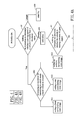
- FIG. 4 which is composed of FIG. 4A and FIG. 4B , is a flow chat showing steps performed in an adaptive surrounding view monitoring method according to the present disclosure.
- the adaptive surrounding view monitoring method comprises the steps of:
- the adaptive surrounding view monitoring apparatus and method of the present disclosure are capable of using a steerable camera set 1 to take a series of images relating to ambient environment of a vehicle 5 for overcoming the problem of image distortion that is commonly seen in the conventional bird-view images.
- the image processing element 23 for processing images while mosaicking the same seamlessly so as to be displayed either an image of 180-degree front or rear surrounding view, or an image of 360-degree ambient surrounding view on the display unit 3 without any blind spot. Consequently, as the resulting image of 180-degree front or rear surrounding view, or image of 360-degree ambient surrounding view can help eliminating all the blind spots existed surrounding the vehicle due to the obstruction of the vehicle's body structure, no additional device is required for detecting the ambient environment of the vehicle.
- the driver of the vehicle is able to selected between the front surrounding view mode 40 , the rear surrounding view mode 41 , and the ambient surrounding view mode 42 using the mode switch 4 , so as to consequently direct the steerable camera set 1 to be orientated adequately for capturing images to be used in the generating of required image of surrounding view.
Landscapes
- Engineering & Computer Science (AREA)
- Multimedia (AREA)
- Mechanical Engineering (AREA)
- Signal Processing (AREA)
- Closed-Circuit Television Systems (AREA)
- Studio Devices (AREA)
Abstract
Description
- This non-provisional application claims priority under 35 U.S.C. §119(a) on Patent Application No. 100111504 filed in Taiwan (R.O.C.) on Apr. 1, 2011, the entire contents of which are hereby incorporated by reference.
- The present disclosure relates to an adaptive surrounding view monitoring apparatus and method thereof, and more particularly, to a monitoring apparatus capable of using a steerable camera set for taking a series of images relating to ambient environment of a vehicle in a horizontal manner while sending the series of images to a control unit to be combined into an image of surrounding view so as to be provided to a driver of the vehicle. Consequently, not only visual blind spots of the driver can be eliminated, but also the field of vision is widened, and thereby, the probability of accident occurring is reduced.
- Pillars are the vertical supports of the passenger compartment of a vehicle, that are known respectively as the A, B, C or D-pillar moving in profile view from the front to rear. Such pillar nomenclature derived from viewing a vehicle in profile can be used as reference points for the passenger compartment of a vehicle. Among which, the A-pillar of a vehicle is the first pillar of the passenger compartment, usually is the one arranged at a position between side-view mirrors and the windshield. The B-pillar of a vehicle is the second pillar of the passenger compartment, after the A-Pillar. The B-pillar, usually used to house the hinges for any rear doors, is the one arranged at a position between the front seats and the rear seats. The C-pillar generally is rearmost pillar supporting the back window and the rear part of a vehicle roof, that is arranged at a position corresponding to the headrest of the rear seat.
- For a driver driving a vehicle, there can be plenty of blind spots existed surrounding the vehicle that cannot be directly observed or through either the rear-view or side-view mirrors by the driver while at the controls due to the obstruction of the vehicle's body structure. Consequently, the driver will have to turn one's head or even change one's body position while negotiating a turn, backing up or changing lane so as to be free from the obstruction of the vehicle's body structure, such as the A-pillars, or the limited field-of-view of its rear-view and side-view mirrors. However, such driving behaviors may increase the risk of collision.
- It is noted that humans have an almost 210-degree forward-facing horizontal field of view. However, the range of visual abilities is not uniform across a field of view. For humans that are not moving, the ability to perceive shape and motion clearly only covers about 70 degrees of the field of view. However, when one is riding on a moving vehicle, the slower the vehicle is moving, the larger the field of view will be, and vice versa. Thus, since a driver's field of view is decreasing with the increasing of driving speed and the driver's field of view can further be restricted by a vehicle's body structure, such as the A-pillars, while driving the vehicle, there can be plenty of blind spots existed surrounding the vehicle and thus any driving condition happening in the adjacent lanes of the vehicle that fall into these blind spots may not be visible and awared by the driver.
- In response to the aforesaid situations, there are already many commercial equipments that can help eliminating blind spots by providing bird-view images showing ambient environment of a vehicle or images respectively capturing the front, left, right and rear view of the vehicle. Nevertheless, those equipments still have the following shortcomings:
-
- 1. For bird-view image, objects shown in a bird-view image, especially those non-ground objects, will be distorted and thus might not be easily identified.
- 2. It is difficult to form a seamless stitching image using a plurality of bird-view images capturing respectively different ambient areas of a vehicle, since there can be ambient areas that are not included in the plural bird-view images.
- 3. For images with overlapping field-of-view, ultrasonic radars are generally being used for detecting the actual situation in that overlapping area.
- 4. Those equipments can only display one image of a single direction or simultaneously two images of two different directions, but are not able to display images of adjacent directions, resulting that there are still blind spots existed.
- To sum up, the equipments that are current available not only fail to provide distortion-free images that can include all the ambient areas of a vehicle without blind spots, but also fail to display images of adjacent directions simultaneously in addition to their having to use additional devices other than those used for generating images.
- The object of the present disclosure is to provide an adaptive surrounding view monitoring apparatus and a method thereof, in which the apparatus uses a steerable camera set to take images while sending the images to an image process unit where they are distorted, aligned and mosaicked into a panoramic image of surrounding view, to be used for assisting a driver to clearly observe the ambient environment of a vehicle at control without any blind spot, and thereby, not only the probability of accident occurring is reduced, but also the prior art shortcomings of failing to display images of adjacent directions simultaneously in addition to their having to use additional devices other than those used for generating images can be prevented.
- To achieve the above object, the present disclosure provides an adaptive surrounding view monitoring apparatus, comprising: a steerable camera set; a control unit, connected to the steerable camera set; a display unit, electrically connected to the control unit; and a mode switch, electrically connected to the control unit.
- Moreover, the present disclosure further provides an adaptive surrounding view monitoring method, comprising the steps of:
-
- making an evaluation to determine whether a moving speed of a vehicle is smaller than a threshold value; if so, enabling a control unit to be situated in an activation state; otherwise, enabling the control unit to be situated in a standby state;
- making an evaluation to determine whether the vehicle is issuing a reverse (R) gear signal; if so, processing an operation for identifying in which mode a mode switch is situated;
- processing an operation for outing a front surrounding view image relating to the front of the vehicle to a display unit for displaying, if the mode switch is identified to be situated in a front surrounding view mode;
- processing an operation for outing a rear surrounding view image relating to the rear of the vehicle to a display unit for displaying, if the mode switch is identified to be situated in a rear surrounding view mode; and
- processing an operation for outing an ambient surrounding view image relating to the ambient environment of the vehicle to a display unit for displaying, if the mode switch is identified to be situated in an ambient surrounding view mode.
- To sum up, the adaptive surrounding view monitoring apparatus and the method thereof that are provided in the present disclosure have the following advantages:
-
- 1. As the steerable camera set is designed to capture images in a horizontal manner, those non-ground objects can be shown without distortion and thus can be easily identified.
- 2. Using the apparatus and method of the present disclosure, an image of 180-degree or 360-degree surrounding view relating to the ambient environment of a vehicle can be obtained, and thereby, the field of view of the driver at control of the vehicle can be widened without any blind spot.
- 3. Since all the blind spots of the vehicle are eliminated using the surrounding view image, there is no need to have additional devices other than those used for generating images to be installed in the monitoring apparatus for detecting ambient environment of the vehicle.
- 4. Since the surrounding view image includes images of adjacent directions or images of multiple directions, not only the field of view is widened, but also the blind spots are eliminated.
- Further scope of applicability of the present application will become more apparent from the detailed description given hereinafter. However, it should be understood that the detailed description and specific examples, while indicating exemplary embodiments of the disclosure, are given by way of illustration only, since various changes and modifications within the spirit and scope of the disclosure will become apparent to those skilled in the art from this detailed description.
- The present disclosure will become more fully understood from the detailed description given herein below and the accompanying drawings which are given by way of illustration only, and thus are not limitative of the present disclosure and wherein:
-
FIG. 1 is a schematic diagram showing an adaptive surrounding view monitoring apparatus according to the present disclosure. -
FIG. 2 is a schematic diagram showing a steerable camera set that is mounted on a vehicle according to an embodiment of the present disclosure. -
FIG. 3 is a schematic diagram showing a steerable camera set that is mounted on a vehicle according to another embodiment of the present disclosure. -
FIG. 4 , being composed ofFIG. 4A andFIG. 4B , is a flow chat showing steps performed in an adaptive surrounding view monitoring method according to the present disclosure. -
FIG. 5 is a schematic diagram showing an image of front surrounding view relating to a vehicle of the present disclosure. -
FIG. 6 is a schematic diagram showing an image of rear surrounding view relating to a vehicle of the present disclosure. -
FIG. 7 is a schematic diagram showing an image of ambient surrounding view relating to a vehicle of the present disclosure. - For your esteemed members of reviewing committee to further understand and recognize the fulfilled functions and structural characteristics of the disclosure, several exemplary embodiments cooperating with detailed description are presented as the follows.
- Please refer to
FIG. 1 , which is a schematic diagram showing an adaptive surrounding view monitoring apparatus according to the present disclosure. As shown inFIG. 1 , the adaptive surrounding view monitoring apparatus comprises: a steerable camera set 1, a control unit 2, a display 3 and a mode switch 4. - In
FIG. 1 , the steerable camera set 1 includes a plurality of steerable cameras, such as the fourcameras micro process units 100, 110, 120, 130, the motor modules 101, 111, 121, 131 and the image sensors 102, 112, 122, 132 respectively for the foursteerable cameras - In this embodiment, the control unit 2 is further configured with a
camera control element 20, animage input element 21, asignal processing element 22, animage processing element 23, amemory element 24, animage output element 25 and animage database 26 - The
camera control element 20 is electrically connected to themicro process units 100, 110, 120, 130 of the fourcameras steerable cameras camera control element 20 is electrically connected to theimage processing element 23, whereas the foursteerable cameras - The
image input element 21 is electrically connected to the image sensor of each steerable camera, i.e. the four images sensors 102, 112, 122, 132, in the steerable camera set 1 where the analog signals from those image sensors are converted into digital signals, and simultaneously theimage input element 21 is electrically connected to theimage processing element 23. - The
signal processing element 22 is provided for processing a signal transmitted from the vehicle, such as a left-turn signal, a right-turn signal, a signal relating to the moving speed of the vehicle, a reverse (R) gear signal, a non-reverse (R) gear signal, a mode switch signal, and so on. As shown inFIG. 1 , thesignal processing element 22 is electrically connected to theimage processing element 23 for transmitting the vehicle signal to theimage processing element 23 for enabling theimage processing element 23 to issue a command correspondingly. - The
image processing element 23 is used for distorting, aligning and mosaicking into a panoramic image of surrounding view and also for device activation control. It is noted that the image mosaicking method for theimage processing element 23 had already been disclosed in TW Pat. Appl. No, 098145942, and thus will not be described further herein. - The
memory element 24, being used for data registering or buffering, is electrically connected to theimage processing element 23. - The
image output element 25, being used for converting digital signals into analog signals, is electrically connected to theimage processing element 23. - Moreover, the
image database 26 is also electrically connected to theimage processing element 23 so as to be used for storing images that are processed by theimage processing element 23. - In addition, the display unit 3 is electrically connected to the
image processing element 23 for image displaying; and the mode switch 4, being embedded with a front surroundingview mode 40, a rear surroundingview mode 41 and an ambientsurrounding view mode 42, is also electrically connected to theimage processing element 23. Moreover, all the aforesaid electrical connections are respectively being enabled by a means selected from the group consisting of: a wired means and a wireless means. - Please refer to
FIG. 2 , which is a schematic diagram showing a steerable camera set that is mounted on a vehicle according to an embodiment of the present disclosure. As shown inFIG. 2 , there is a steerable camera set 1 mounted on avehicle 5, whereas thevehicle 5 is configured with a front 53, a rear 54, two A-pillars 50, two B-pillars 51, a C-pillars 52 and two rear-view mirrors 55 in a manner that the two A-pillars 50 are disposed respectively at the two sides of thevehicle 5, which are the same to the two B-pillars 51 and the two C-pillars 52, while the two rear-view mirrors 55 are arranged at positions respectively corresponding to the two A-pillars 50. - In
FIG. 2 , thesteerable camera 10 is arranged at the middle of thefront 53 of thevehicle 5, and thus is being grouped in the first steerable camera group; thesteerable camera 11 is arranged at the left side of thevehicle 5 at a position between the left A-pillar 50 and the left C-pillar 52 or at a position corresponding to the left B-pillar 51, and thus is being grouped in the second steerable camera group; thesteerable camera 12 is arranged at the right side of thevehicle 5 at a position between the right A-pillar 50 and the right C-pillar 52 or at a position corresponding to the right B-pillar 51, and thus is being grouped in the third steerable camera group; and thesteerable camera 13 is arranged at the middle of the rear 54 of thevehicle 5, and thus is being grouped in the fourth steerable camera group. - Please refer to
FIG. 3 is a schematic diagram showing a steerable camera set that is mounted on a vehicle according to another embodiment of the present disclosure. InFIG. 3 , thecameras FIG. 2 , while the twocameras view mirror 55 in respectively. - Moreover, the control unit 2, the display unit 3 and the mode switch 4 can be arranged inside the frame of the
vehicle 5, in which the mode switch 4 and the display unit 3 should be arranged at positions proximate to a driver of thevehicle 5 so as to facilitating the driver to easily view the images displayed on the display unit 3 and also to change to the required image mode through the control of the mode switch 4. - The foregoing description only describes the components for an adaptive surrounding view monitoring apparatus and how the adaptive surrounding view monitoring apparatus is constructed using the aforesaid components. The description provided hereinafter will relates to an adaptive surrounding view monitoring method. Please refer to
FIG. 4 , which is composed ofFIG. 4A andFIG. 4B , is a flow chat showing steps performed in an adaptive surrounding view monitoring method according to the present disclosure. - In
FIG. 4 , the adaptive surrounding view monitoring method comprises the steps of: -
- step 60: making an evaluation to determine whether a moving speed of a vehicle is smaller than a threshold value, whereas the threshold value is a defined value relating to the moving speed of the vehicle that is adjustable; if the moving speed is smaller than the threshold value, the flow proceeds to step 601 for enabling a control unit 2 to be situated in an activation state and the proceeds to step 61; otherwise, the flow proceeds to step 600 for enabling the control unit 2 to be situated in a standby state;
- step 61: making an evaluation to determine whether the vehicle is issuing a reverse (R) gear signal; if so, the flow proceeds to step 610 where an operation is processed for identifying in which mode a mode switch 4 is situated, and thereafter, if the mode switch 4 is identified to be situated in the front surrounding
view mode 40, the flow will proceed to step 611, if the mode switch 4 is identified to be situated in the rear surroundingview mode 41, the flow will proceed to step 612, and if the mode switch 4 is identified to be situated in the ambient surroundingview mode 42, the flow will proceed to step 612; otherwise, the flow proceeds to step 62; - step 611: when the mode switch 4 is situated in the front surrounding
view mode 40, enabling acamera control element 20 to control the micro process units 100, 110, 120 and motor modules 101, 111, 121 incameras cameras image processing element 23 through animage input element 21 where they are distorted, aligned and mosaicked into the image of 180-degree surrounding view to the front of thevehicle 5 to the display unit 3 through animage output element 25, as shown inFIG. 5 ; - step 612: when the mode switch 4 is situated in the rear surrounding
view mode 41, enabling thecamera control element 20 to control thecameras cameras image processing element 23 through animage input element 21 where they are distorted, aligned and mosaicked into the image of 180-degree surrounding view to the rear of thevehicle 5 to the display unit 3 through animage output element 25, as shown inFIG. 6 ; - Step 613: when the mode switch 4 is situated in the ambient surrounding
view mode 42, enabling thecamera control element 20 to control thecameras cameras image processing element 23 through animage input element 21 where they are distorted, aligned and mosaicked into the image of 360-degree surrounding view to the ambient environment of thevehicle 5 to the display unit 3 through animage output element 25, as shown inFIG. 7 ; - step 62: determining whether the
vehicle 5 is issuing a signal selected from the group consisting of: a left-turn signal and a right-turn signal, if there in no such left-turn signal or right-turn signal being issued, the flow will proceeds to step 624; otherwise, the flow proceeds to step 620; - step 620: performing the operation for identifying in which mode a mode switch 4 is situated, and thereafter, if the mode switch 4 is identified to be situated in the front surrounding
view mode 40, the flow will proceed to step 621, if the mode switch 4 is identified to be situated in the rear surroundingview mode 41, the flow will proceed to step 622, and if the mode switch 4 is identified to be situated in the ambient surroundingview mode 42, the flow will proceed to step 623; - step 621: when the mode switch 4 is situated in the front surrounding
view mode 40, enabling acamera control element 20 to control thecameras cameras image processing element 23 through animage input element 21 where they are distorted, aligned and mosaicked into the image of 180-degree surrounding view to the front of thevehicle 5 to the display unit 3 through animage output element 25, as shown inFIG. 5 ; - step 622: when the mode switch 4 is situated in the rear surrounding
view mode 41, enabling thecamera control element 20 to control thecameras cameras image processing element 23 through animage input element 21 where they are distorted, aligned and mosaicked into the image of 180-degree surrounding view to the rear of thevehicle 5 to the display unit 3 through animage output element 25, as shown inFIG. 6 ; - step 623: when the mode switch 4 is situated in the ambient surrounding
view mode 42, enabling thecamera control element 20 to control thecameras cameras image processing element 23 through animage input element 21 where they are distorted, aligned and mosaicked into the image of 360-degree surrounding view to the ambient environment of thevehicle 5 to the display unit 3 through animage output element 25, as shown inFIG. 7 ; - step 624: performing the operation for identifying in which mode a mode switch 4 is situated, and thereafter, if the mode switch 4 is identified to be situated in the front surrounding
view mode 40, the flow will proceed to step 625, if the mode switch 4 is identified to be situated in the rear surroundingview mode 41, the flow will proceed to step 626, and if the mode switch 4 is identified to be situated in the ambient surroundingview mode 42, the flow will proceed to step 627; - step 625: when the mode switch 4 is situated in the front surrounding
view mode 40, enabling acamera control element 20 to control thecameras cameras image processing element 23 through animage input element 21 where they are distorted, aligned and mosaicked into the image of 180-degree surrounding view to the front of thevehicle 5 to the display unit 3 through animage output element 25, as shown inFIG. 5 ; - step 626: when the mode switch 4 is situated in the rear surrounding
view mode 41, enabling thecamera control element 20 to control thecameras cameras image processing element 23 through animage input element 21 where they are distorted, aligned and mosaicked into the image of 180-degree surrounding view to the rear of thevehicle 5 to the display unit 3 through animage output element 25, as shown inFIG. 6 ; and - step 627: when the mode switch 4 is situated in the ambient surrounding
view mode 42, enabling thecamera control element 20 to control thecameras cameras image processing element 23 through animage input element 21 where they are distorted, aligned and mosaicked into the image of 360-degree surrounding view to the ambient environment of the vehicle.
- To sum up, the adaptive surrounding view monitoring apparatus and method of the present disclosure are capable of using a steerable camera set 1 to take a series of images relating to ambient environment of a
vehicle 5 for overcoming the problem of image distortion that is commonly seen in the conventional bird-view images. - Moreover, by the use of the
image processing element 23 for processing images while mosaicking the same seamlessly so as to be displayed either an image of 180-degree front or rear surrounding view, or an image of 360-degree ambient surrounding view on the display unit 3 without any blind spot. Consequently, as the resulting image of 180-degree front or rear surrounding view, or image of 360-degree ambient surrounding view can help eliminating all the blind spots existed surrounding the vehicle due to the obstruction of the vehicle's body structure, no additional device is required for detecting the ambient environment of the vehicle. - Furthermore, the driver of the vehicle is able to selected between the front surrounding
view mode 40, the rear surroundingview mode 41, and the ambient surroundingview mode 42 using the mode switch 4, so as to consequently direct the steerable camera set 1 to be orientated adequately for capturing images to be used in the generating of required image of surrounding view. - With respect to the above description then, it is to be realized that the optimum dimensional relationships for the parts of the disclosure, to include variations in size, materials, shape, form, function and manner of operation, assembly and use, are deemed readily apparent and obvious to one skilled in the art, and all equivalent relationships to those illustrated in the drawings and described in the specification are intended to be encompassed by the present disclosure.
Claims (20)
Applications Claiming Priority (3)
| Application Number | Priority Date | Filing Date | Title |
|---|---|---|---|
| TW100111504A | 2011-04-01 | ||
| TW100111504A TWI421624B (en) | 2011-04-01 | 2011-04-01 | Adaptive surrounding view monitoring apparatus and method thereof |
| TW100111504 | 2011-04-01 |
Publications (2)
| Publication Number | Publication Date |
|---|---|
| US20120249791A1 true US20120249791A1 (en) | 2012-10-04 |
| US8823796B2 US8823796B2 (en) | 2014-09-02 |
Family
ID=46926734
Family Applications (1)
| Application Number | Title | Priority Date | Filing Date |
|---|---|---|---|
| US13/157,966 Active 2032-10-12 US8823796B2 (en) | 2011-04-01 | 2011-06-10 | Adaptive surrounding view monitoring apparatus and method thereof |
Country Status (3)
| Country | Link |
|---|---|
| US (1) | US8823796B2 (en) |
| CN (1) | CN102740055A (en) |
| TW (1) | TWI421624B (en) |
Cited By (15)
| Publication number | Priority date | Publication date | Assignee | Title |
|---|---|---|---|---|
| US20120105642A1 (en) * | 2009-06-29 | 2012-05-03 | Panasonic Corporation | Vehicle-mounted video display device |
| US20140211007A1 (en) * | 2013-01-28 | 2014-07-31 | Fujitsu Ten Limited | Object detector |
| US20140267688A1 (en) * | 2011-04-19 | 2014-09-18 | Ford Global Technologies, Llc | Display system utilizing vehicle and trailer dynamics |
| US20150015710A1 (en) * | 2013-07-09 | 2015-01-15 | Magna Electronics Inc. | Vehicle vision system |
| US20150103159A1 (en) * | 2013-10-14 | 2015-04-16 | Mobileye Vision Technologies Ltd. | Forward-facing multi-imaging system for navigating a vehicle |
| US9387813B1 (en) * | 2012-03-21 | 2016-07-12 | Road-Iq, Llc | Device, system and method for aggregating networks and serving data from those networks to computers |
| CN105774654A (en) * | 2016-03-02 | 2016-07-20 | 广州三晶智能电子技术有限公司 | Car blind spot visible steering system and control method |
| US20170024933A1 (en) * | 2015-07-21 | 2017-01-26 | Utherverse Digital Inc. | Immersive displays |
| EP3235685A1 (en) * | 2014-05-30 | 2017-10-25 | LG Electronics Inc. | Surround view vision apparatus and vehicle including the same |
| US10589676B2 (en) | 2016-06-02 | 2020-03-17 | Magna Electronics Inc. | Vehicle display system with user input display |
| US11042996B2 (en) * | 2016-12-13 | 2021-06-22 | Denso Corporation | Recognition apparatus |
| US11170227B2 (en) | 2014-04-08 | 2021-11-09 | Bendix Commercial Vehicle Systems Llc | Generating an image of the surroundings of an articulated vehicle |
| US20230001922A1 (en) * | 2021-07-01 | 2023-01-05 | Triple Win Technology(Shenzhen) Co.Ltd. | System providing blind spot safety warning to driver, method, and vehicle with system |
| WO2024013585A1 (en) * | 2022-07-15 | 2024-01-18 | Agco International Gmbh | A vehicle with a sensor unit for environmental perception |
| EP4202885A4 (en) * | 2020-09-24 | 2024-04-24 | Huawei Tech Co Ltd | Device control method and apparatus, and device |
Families Citing this family (39)
| Publication number | Priority date | Publication date | Assignee | Title |
|---|---|---|---|---|
| GB2447672B (en) | 2007-03-21 | 2011-12-14 | Ford Global Tech Llc | Vehicle manoeuvring aids |
| US9683848B2 (en) | 2011-04-19 | 2017-06-20 | Ford Global Technologies, Llc | System for determining hitch angle |
| US9926008B2 (en) | 2011-04-19 | 2018-03-27 | Ford Global Technologies, Llc | Trailer backup assist system with waypoint selection |
| US9506774B2 (en) | 2011-04-19 | 2016-11-29 | Ford Global Technologies, Llc | Method of inputting a path for a vehicle and trailer |
| US9723274B2 (en) | 2011-04-19 | 2017-08-01 | Ford Global Technologies, Llc | System and method for adjusting an image capture setting |
| US9937953B2 (en) | 2011-04-19 | 2018-04-10 | Ford Global Technologies, Llc | Trailer backup offset determination |
| US9969428B2 (en) | 2011-04-19 | 2018-05-15 | Ford Global Technologies, Llc | Trailer backup assist system with waypoint selection |
| US9500497B2 (en) | 2011-04-19 | 2016-11-22 | Ford Global Technologies, Llc | System and method of inputting an intended backing path |
| US9592851B2 (en) | 2013-02-04 | 2017-03-14 | Ford Global Technologies, Llc | Control modes for a trailer backup assist system |
| US9511799B2 (en) | 2013-02-04 | 2016-12-06 | Ford Global Technologies, Llc | Object avoidance for a trailer backup assist system |
| DE102013213812A1 (en) * | 2013-07-15 | 2015-01-15 | Volkswagen Aktiengesellschaft | Device and method for displaying a traffic situation in a vehicle |
| CN104340121A (en) * | 2013-08-01 | 2015-02-11 | 怡利电子工业股份有限公司 | Driving recorder with video recording and automatic display switching function and frame display method of driving recorder |
| CN104972971A (en) * | 2014-04-08 | 2015-10-14 | 王学建 | Automobile lateral safety electric monitoring instrument |
| KR101631963B1 (en) * | 2014-04-30 | 2016-06-20 | 엘지전자 주식회사 | Head up display device and vehicle having the same |
| DE102014008687A1 (en) * | 2014-06-12 | 2015-12-17 | GM Global Technology Operations LLC (n. d. Ges. d. Staates Delaware) | Method for displaying vehicle surroundings information of a motor vehicle |
| US9533683B2 (en) | 2014-12-05 | 2017-01-03 | Ford Global Technologies, Llc | Sensor failure mitigation system and mode management |
| US9522677B2 (en) | 2014-12-05 | 2016-12-20 | Ford Global Technologies, Llc | Mitigation of input device failure and mode management |
| US9607242B2 (en) | 2015-01-16 | 2017-03-28 | Ford Global Technologies, Llc | Target monitoring system with lens cleaning device |
| US9751558B2 (en) | 2015-03-25 | 2017-09-05 | Ford Global Technologies, Llc | Handwheel obstruction detection and inertia compensation |
| US9616928B2 (en) | 2015-03-25 | 2017-04-11 | Ford Global Technologies, Llc | Steering angle control for multiple features |
| CN104960473B (en) * | 2015-07-03 | 2017-11-14 | 上海寅喆计算机科技有限公司 | View angle switch method and device |
| US9849864B2 (en) | 2015-07-31 | 2017-12-26 | Ford Global Technologies, Llc | Vehicle parking assist system |
| US9896130B2 (en) | 2015-09-11 | 2018-02-20 | Ford Global Technologies, Llc | Guidance system for a vehicle reversing a trailer along an intended backing path |
| US9981656B2 (en) | 2015-10-13 | 2018-05-29 | Ford Global Technologies, Llc | Vehicle parking assist system |
| TWI582388B (en) | 2015-10-16 | 2017-05-11 | 財團法人工業技術研究院 | Image stitching method and image stitching device |
| US9836060B2 (en) | 2015-10-28 | 2017-12-05 | Ford Global Technologies, Llc | Trailer backup assist system with target management |
| US10328933B2 (en) | 2015-10-29 | 2019-06-25 | Ford Global Technologies, Llc | Cognitive reverse speed limiting |
| TWI607901B (en) * | 2015-11-06 | 2017-12-11 | 財團法人工業技術研究院 | Image inpainting system area and method using the same |
| US9895945B2 (en) | 2015-12-08 | 2018-02-20 | Ford Global Technologies, Llc | Trailer backup assist system with hitch assist |
| CN105459907B (en) * | 2015-12-15 | 2018-02-02 | 小米科技有限责任公司 | Vehicle security system, blind area monitoring method and device |
| CN105704449A (en) * | 2016-01-28 | 2016-06-22 | 深圳市国显科技有限公司 | A vehicle-mounted look-around display method and a system thereof |
| EP3206184A1 (en) | 2016-02-11 | 2017-08-16 | NXP USA, Inc. | Apparatus, method and system for adjusting predefined calibration data for generating a perspective view |
| US10112646B2 (en) | 2016-05-05 | 2018-10-30 | Ford Global Technologies, Llc | Turn recovery human machine interface for trailer backup assist |
| US9829883B1 (en) | 2016-10-17 | 2017-11-28 | Ford Global Technologies, Llc | Trailer backup assist system having remote control and user sight management |
| US10609339B2 (en) * | 2017-03-22 | 2020-03-31 | GM Global Technology Operations LLC | System for and method of dynamically displaying images on a vehicle electronic display |
| CN109089086B (en) * | 2018-10-09 | 2024-04-05 | 上海宏英智能科技股份有限公司 | Panoramic camera system |
| US10694105B1 (en) | 2018-12-24 | 2020-06-23 | Wipro Limited | Method and system for handling occluded regions in image frame to generate a surround view |
| BR112021016305B1 (en) | 2019-02-19 | 2024-03-05 | Orlaco Products B.V | CAMERA MIRROR SYSTEM FOR A VEHICLE AND METHOD OF DISPLAYING MULTIPLE VEHICLE CAMERA VIEWS |
| US10497232B1 (en) * | 2019-03-01 | 2019-12-03 | Motorola Solutions, Inc. | System and method for dynamic vehicular threat detection perimeter modification for an exited vehicular occupant |
Citations (21)
| Publication number | Priority date | Publication date | Assignee | Title |
|---|---|---|---|---|
| US5680123A (en) * | 1996-08-06 | 1997-10-21 | Lee; Gul Nam | Vehicle monitoring system |
| US6535242B1 (en) * | 2000-10-24 | 2003-03-18 | Gary Steven Strumolo | System and method for acquiring and displaying vehicular information |
| US20030080877A1 (en) * | 2001-10-31 | 2003-05-01 | Makoto Takagi | Device for monitoring area around vehicle |
| US20030090570A1 (en) * | 2001-11-12 | 2003-05-15 | Makoto Takagi | Vehicle periphery monitor |
| US20030137586A1 (en) * | 2002-01-22 | 2003-07-24 | Infinite Innovations, Inc. | Vehicle video switching system and method |
| US20050174429A1 (en) * | 2004-02-04 | 2005-08-11 | Nissan Motor Co., Ltd. | System for monitoring vehicle surroundings |
| US20050225636A1 (en) * | 2004-03-26 | 2005-10-13 | Mitsubishi Jidosha Kogyo Kabushiki Kaisha | Nose-view monitoring apparatus |
| US20050240342A1 (en) * | 2004-04-22 | 2005-10-27 | Nobuaki Ishihara | Vehicle periphery display control system |
| US20060119472A1 (en) * | 2004-11-09 | 2006-06-08 | Shoichi Tsuboi | Driving support apparatus and driving support method |
| US20060215020A1 (en) * | 2005-03-23 | 2006-09-28 | Aisin Aw Co., Ltd. | Visual recognition apparatus, methods, and programs for vehicles |
| US7171027B2 (en) * | 2002-03-05 | 2007-01-30 | Nissan Motor Co., Ltd. | Vehicular image processing apparatus and related method |
| US20070299584A1 (en) * | 1998-10-08 | 2007-12-27 | Matsushita Electric Industrial Co., Ltd. | Driving-operation assist and recording medium |
| US20080055411A1 (en) * | 2006-09-06 | 2008-03-06 | Dong Wook Lee | External Monitoring System for Securing Driver's Field of Vision for Vehicles |
| US20090085913A1 (en) * | 2007-09-21 | 2009-04-02 | Honda Motor Co., Ltd. | Road shape estimating device |
| US20090143967A1 (en) * | 2007-12-04 | 2009-06-04 | Volkswagen Of America, Inc. | Motor Vehicle Having a Wheel-View Camera and Method for Controlling a Wheel-View Camera System |
| US20100066518A1 (en) * | 2008-09-16 | 2010-03-18 | Honda Motor Co., Ltd. | Vehicle surroundings monitoring apparatus |
| US20100220189A1 (en) * | 2005-08-02 | 2010-09-02 | Takura Yanagi | Device and method for monitoring vehicle surroundings |
| US20110106380A1 (en) * | 2009-11-02 | 2011-05-05 | Denso Corporation | Vehicle surrounding monitoring device |
| US20110181406A1 (en) * | 2010-01-27 | 2011-07-28 | Hon Hai Precision Industry Co., Ltd. | Display system and vehicle having the same |
| US20120158256A1 (en) * | 2009-07-22 | 2012-06-21 | Aisin Seiki Kabushiki Kaisha | Driving support device |
| US20130155236A1 (en) * | 2011-12-15 | 2013-06-20 | Pradeep Ramdeo | Camera-mirror system for motor vehicle |
Family Cites Families (12)
| Publication number | Priority date | Publication date | Assignee | Title |
|---|---|---|---|---|
| JP4766841B2 (en) * | 2003-09-08 | 2011-09-07 | 株式会社オートネットワーク技術研究所 | Camera device and vehicle periphery monitoring device mounted on vehicle |
| TW200740644A (en) * | 2006-04-28 | 2007-11-01 | Hen Shen Entpr Co Ltd | Apparatus and method of surround photographing and monitoring |
| JP5347257B2 (en) * | 2007-09-26 | 2013-11-20 | 日産自動車株式会社 | Vehicle periphery monitoring device and video display method |
| TWM332046U (en) | 2007-10-19 | 2008-05-11 | Yuan-Peng Ding | Image survelliance system for automobile |
| TWI361396B (en) | 2008-01-18 | 2012-04-01 | Univ Nat Chiao Tung | Image synthesis system for a vehicle and the manufacturing method thereof mage synthesis device and method |
| CN101415110B (en) * | 2008-11-19 | 2011-04-27 | 符巨章 | System for monitoring dynamic vehicle |
| JP2010166196A (en) * | 2009-01-14 | 2010-07-29 | Clarion Co Ltd | Vehicle periphery monitoring device |
| CN101790077A (en) * | 2009-01-22 | 2010-07-28 | 广东电子工业研究院有限公司 | Vehicular multifunctional rotary image pick-up system |
| TWM373507U (en) | 2009-02-05 | 2010-02-01 | Shen-Jwu Su | Three-dimensional vision panoramic image splicing mosaics device |
| JP4770942B2 (en) * | 2009-02-19 | 2011-09-14 | 株式会社デンソー | Outside-vehicle image display system and vehicle |
| JP5344227B2 (en) * | 2009-03-25 | 2013-11-20 | アイシン精機株式会社 | Vehicle periphery monitoring device |
| TWM371664U (en) * | 2009-07-07 | 2010-01-01 | Univ Southern Taiwan Tech | Car image-capturing device capable of changing viewing angle faccording to speed of car |
-
2011
- 2011-04-01 TW TW100111504A patent/TWI421624B/en active
- 2011-04-27 CN CN2011101061704A patent/CN102740055A/en active Pending
- 2011-06-10 US US13/157,966 patent/US8823796B2/en active Active
Patent Citations (21)
| Publication number | Priority date | Publication date | Assignee | Title |
|---|---|---|---|---|
| US5680123A (en) * | 1996-08-06 | 1997-10-21 | Lee; Gul Nam | Vehicle monitoring system |
| US20070299584A1 (en) * | 1998-10-08 | 2007-12-27 | Matsushita Electric Industrial Co., Ltd. | Driving-operation assist and recording medium |
| US6535242B1 (en) * | 2000-10-24 | 2003-03-18 | Gary Steven Strumolo | System and method for acquiring and displaying vehicular information |
| US20030080877A1 (en) * | 2001-10-31 | 2003-05-01 | Makoto Takagi | Device for monitoring area around vehicle |
| US20030090570A1 (en) * | 2001-11-12 | 2003-05-15 | Makoto Takagi | Vehicle periphery monitor |
| US20030137586A1 (en) * | 2002-01-22 | 2003-07-24 | Infinite Innovations, Inc. | Vehicle video switching system and method |
| US7171027B2 (en) * | 2002-03-05 | 2007-01-30 | Nissan Motor Co., Ltd. | Vehicular image processing apparatus and related method |
| US20050174429A1 (en) * | 2004-02-04 | 2005-08-11 | Nissan Motor Co., Ltd. | System for monitoring vehicle surroundings |
| US20050225636A1 (en) * | 2004-03-26 | 2005-10-13 | Mitsubishi Jidosha Kogyo Kabushiki Kaisha | Nose-view monitoring apparatus |
| US20050240342A1 (en) * | 2004-04-22 | 2005-10-27 | Nobuaki Ishihara | Vehicle periphery display control system |
| US20060119472A1 (en) * | 2004-11-09 | 2006-06-08 | Shoichi Tsuboi | Driving support apparatus and driving support method |
| US20060215020A1 (en) * | 2005-03-23 | 2006-09-28 | Aisin Aw Co., Ltd. | Visual recognition apparatus, methods, and programs for vehicles |
| US20100220189A1 (en) * | 2005-08-02 | 2010-09-02 | Takura Yanagi | Device and method for monitoring vehicle surroundings |
| US20080055411A1 (en) * | 2006-09-06 | 2008-03-06 | Dong Wook Lee | External Monitoring System for Securing Driver's Field of Vision for Vehicles |
| US20090085913A1 (en) * | 2007-09-21 | 2009-04-02 | Honda Motor Co., Ltd. | Road shape estimating device |
| US20090143967A1 (en) * | 2007-12-04 | 2009-06-04 | Volkswagen Of America, Inc. | Motor Vehicle Having a Wheel-View Camera and Method for Controlling a Wheel-View Camera System |
| US20100066518A1 (en) * | 2008-09-16 | 2010-03-18 | Honda Motor Co., Ltd. | Vehicle surroundings monitoring apparatus |
| US20120158256A1 (en) * | 2009-07-22 | 2012-06-21 | Aisin Seiki Kabushiki Kaisha | Driving support device |
| US20110106380A1 (en) * | 2009-11-02 | 2011-05-05 | Denso Corporation | Vehicle surrounding monitoring device |
| US20110181406A1 (en) * | 2010-01-27 | 2011-07-28 | Hon Hai Precision Industry Co., Ltd. | Display system and vehicle having the same |
| US20130155236A1 (en) * | 2011-12-15 | 2013-06-20 | Pradeep Ramdeo | Camera-mirror system for motor vehicle |
Cited By (28)
| Publication number | Priority date | Publication date | Assignee | Title |
|---|---|---|---|---|
| US20120105642A1 (en) * | 2009-06-29 | 2012-05-03 | Panasonic Corporation | Vehicle-mounted video display device |
| US9854209B2 (en) * | 2011-04-19 | 2017-12-26 | Ford Global Technologies, Llc | Display system utilizing vehicle and trailer dynamics |
| US20140267688A1 (en) * | 2011-04-19 | 2014-09-18 | Ford Global Technologies, Llc | Display system utilizing vehicle and trailer dynamics |
| US10609340B2 (en) | 2011-04-19 | 2020-03-31 | Ford Global Technologies, Llc | Display system utilizing vehicle and trailer dynamics |
| US9387813B1 (en) * | 2012-03-21 | 2016-07-12 | Road-Iq, Llc | Device, system and method for aggregating networks and serving data from those networks to computers |
| US10109116B2 (en) * | 2012-03-21 | 2018-10-23 | Road-Iq, Llc | Device, system and method for aggregating networks and serving data from those networks to computers |
| US20170039782A1 (en) * | 2012-03-21 | 2017-02-09 | Road-Iq, Llc | Device, System and Method for Aggregating Networks and Serving Data from Those Networks to Computers |
| US20140211007A1 (en) * | 2013-01-28 | 2014-07-31 | Fujitsu Ten Limited | Object detector |
| US9811741B2 (en) * | 2013-01-28 | 2017-11-07 | Fujitsu Ten Limited | Object detector |
| US20150015710A1 (en) * | 2013-07-09 | 2015-01-15 | Magna Electronics Inc. | Vehicle vision system |
| US9701258B2 (en) * | 2013-07-09 | 2017-07-11 | Magna Electronics Inc. | Vehicle vision system |
| US10065574B2 (en) | 2013-07-09 | 2018-09-04 | Magna Electronics Inc. | Vehicle vision system with gesture determination |
| US20150103159A1 (en) * | 2013-10-14 | 2015-04-16 | Mobileye Vision Technologies Ltd. | Forward-facing multi-imaging system for navigating a vehicle |
| US10318823B2 (en) * | 2013-10-14 | 2019-06-11 | Mobileye Vision Technologies Ltd. | Forward-facing multi-imaging system for navigating a vehicle |
| US11126865B2 (en) * | 2013-10-14 | 2021-09-21 | Mobileye Vision Technologies Ltd. | Forward-facing multi-imaging system for navigating a vehicle |
| US10650254B2 (en) | 2013-10-14 | 2020-05-12 | Mobileye Vision Technologies Ltd. | Forward-facing multi-imaging system for navigating a vehicle |
| EP3117406A4 (en) * | 2014-03-13 | 2017-12-20 | Road-IQ, LLC | Device, system and method for aggregating networks and serving data from those networks to computers |
| US11170227B2 (en) | 2014-04-08 | 2021-11-09 | Bendix Commercial Vehicle Systems Llc | Generating an image of the surroundings of an articulated vehicle |
| EP3235685A1 (en) * | 2014-05-30 | 2017-10-25 | LG Electronics Inc. | Surround view vision apparatus and vehicle including the same |
| US20170024933A1 (en) * | 2015-07-21 | 2017-01-26 | Utherverse Digital Inc. | Immersive displays |
| US10464482B2 (en) * | 2015-07-21 | 2019-11-05 | Utherverse Digital Inc. | Immersive displays |
| CN105774654A (en) * | 2016-03-02 | 2016-07-20 | 广州三晶智能电子技术有限公司 | Car blind spot visible steering system and control method |
| US10589676B2 (en) | 2016-06-02 | 2020-03-17 | Magna Electronics Inc. | Vehicle display system with user input display |
| US11124118B2 (en) | 2016-06-02 | 2021-09-21 | Magna Electronics Inc. | Vehicular display system with user input display |
| US11042996B2 (en) * | 2016-12-13 | 2021-06-22 | Denso Corporation | Recognition apparatus |
| EP4202885A4 (en) * | 2020-09-24 | 2024-04-24 | Huawei Tech Co Ltd | Device control method and apparatus, and device |
| US20230001922A1 (en) * | 2021-07-01 | 2023-01-05 | Triple Win Technology(Shenzhen) Co.Ltd. | System providing blind spot safety warning to driver, method, and vehicle with system |
| WO2024013585A1 (en) * | 2022-07-15 | 2024-01-18 | Agco International Gmbh | A vehicle with a sensor unit for environmental perception |
Also Published As
| Publication number | Publication date |
|---|---|
| US8823796B2 (en) | 2014-09-02 |
| TW201241548A (en) | 2012-10-16 |
| CN102740055A (en) | 2012-10-17 |
| TWI421624B (en) | 2014-01-01 |
Similar Documents
| Publication | Publication Date | Title |
|---|---|---|
| US8823796B2 (en) | Adaptive surrounding view monitoring apparatus and method thereof | |
| US9998675B2 (en) | Rearview imaging system for vehicle | |
| CN107399275B (en) | Vehicle occupant observation system and method | |
| US20130096820A1 (en) | Virtual display system for a vehicle | |
| US10462354B2 (en) | Vehicle control system utilizing multi-camera module | |
| US8854466B2 (en) | Rearward view assistance apparatus displaying cropped vehicle rearward image | |
| US8498770B2 (en) | Vehicle parking assist system and method | |
| US8665331B2 (en) | In-vehicle image display apparatus | |
| US20190100156A1 (en) | System and method for controlling a display | |
| JP2018157403A (en) | On-vehicle display device, control method for on-vehicle display device, and control program for on-vehicle display device | |
| JP2018122757A (en) | Parking assisting-device | |
| JP6072470B2 (en) | In-vehicle imaging system | |
| US20190100145A1 (en) | Three-dimensional image driving assistance device | |
| US20170116710A1 (en) | Merging of Partial Images to Form an Image of Surroundings of a Mode of Transport | |
| US20100289631A1 (en) | Dual-mode vehicle rear vision system | |
| US10999559B1 (en) | Electronic side-mirror with multiple fields of view | |
| US20210331680A1 (en) | Vehicle driving assistance apparatus | |
| JP2018142885A (en) | Vehicular display control apparatus, vehicular display system, vehicular display control method, and program | |
| WO2015013311A1 (en) | Vehicle imaging system | |
| CN202174989U (en) | 360-degree full shot camera system for car parking | |
| KR101980966B1 (en) | Method and device for representing the surroundings of a motor vehicle | |
| US20150085117A1 (en) | Driving assistance apparatus | |
| JP2010006129A (en) | Vehicle rear information display and vehicle rear information display method | |
| US20220144169A1 (en) | Rear-view camera system for a trailer hitch system | |
| US10735638B2 (en) | Dual display reverse camera system |
Legal Events
| Date | Code | Title | Description |
|---|---|---|---|
| AS | Assignment |
Owner name: INDUSTRIAL TECHNOLOGY RESEARCH INSTITUTE, TAIWAN Free format text: ASSIGNMENT OF ASSIGNORS INTEREST;ASSIGNORS:SHEN, HSIN-LIANG;CHENG, KUO-HSIANG;TUAN, TSUNG-TYNG;AND OTHERS;REEL/FRAME:026427/0644 Effective date: 20110503 |
|
| STCF | Information on status: patent grant |
Free format text: PATENTED CASE |
|
| FEPP | Fee payment procedure |
Free format text: PAYOR NUMBER ASSIGNED (ORIGINAL EVENT CODE: ASPN); ENTITY STATUS OF PATENT OWNER: LARGE ENTITY Free format text: PAYER NUMBER DE-ASSIGNED (ORIGINAL EVENT CODE: RMPN); ENTITY STATUS OF PATENT OWNER: LARGE ENTITY |
|
| MAFP | Maintenance fee payment |
Free format text: PAYMENT OF MAINTENANCE FEE, 4TH YEAR, LARGE ENTITY (ORIGINAL EVENT CODE: M1551) Year of fee payment: 4 |
|
| MAFP | Maintenance fee payment |
Free format text: PAYMENT OF MAINTENANCE FEE, 8TH YEAR, LARGE ENTITY (ORIGINAL EVENT CODE: M1552); ENTITY STATUS OF PATENT OWNER: LARGE ENTITY Year of fee payment: 8 |