US20120249124A1 - Omnipolar magnetic switches - Google Patents
Omnipolar magnetic switches Download PDFInfo
- Publication number
- US20120249124A1 US20120249124A1 US13/076,593 US201113076593A US2012249124A1 US 20120249124 A1 US20120249124 A1 US 20120249124A1 US 201113076593 A US201113076593 A US 201113076593A US 2012249124 A1 US2012249124 A1 US 2012249124A1
- Authority
- US
- United States
- Prior art keywords
- comparator
- negative
- positive
- electric signal
- coupled
- Prior art date
- Legal status (The legal status is an assumption and is not a legal conclusion. Google has not performed a legal analysis and makes no representation as to the accuracy of the status listed.)
- Granted
Links
- 230000005355 Hall effect Effects 0.000 claims abstract description 4
- 238000000605 extraction Methods 0.000 claims abstract description 4
- 230000007704 transition Effects 0.000 claims description 31
- 238000001514 detection method Methods 0.000 claims description 17
- 238000000034 method Methods 0.000 claims description 10
- 238000011156 evaluation Methods 0.000 abstract description 4
- 238000012545 processing Methods 0.000 abstract description 3
- 238000005070 sampling Methods 0.000 abstract description 2
- 238000010586 diagram Methods 0.000 description 4
- 101150001015 BOP1 gene Proteins 0.000 description 3
- 238000010348 incorporation Methods 0.000 description 3
- 238000012986 modification Methods 0.000 description 3
- 230000004048 modification Effects 0.000 description 3
- 230000036039 immunity Effects 0.000 description 2
- 230000008878 coupling Effects 0.000 description 1
- 238000010168 coupling process Methods 0.000 description 1
- 238000005859 coupling reaction Methods 0.000 description 1
- 230000001419 dependent effect Effects 0.000 description 1
- 230000001105 regulatory effect Effects 0.000 description 1
- 238000004088 simulation Methods 0.000 description 1
- 238000009987 spinning Methods 0.000 description 1
Images


Classifications
-
- H—ELECTRICITY
- H03—ELECTRONIC CIRCUITRY
- H03K—PULSE TECHNIQUE
- H03K17/00—Electronic switching or gating, i.e. not by contact-making and –breaking
- H03K17/94—Electronic switching or gating, i.e. not by contact-making and –breaking characterised by the way in which the control signals are generated
- H03K17/945—Proximity switches
- H03K17/95—Proximity switches using a magnetic detector
- H03K17/9517—Proximity switches using a magnetic detector using galvanomagnetic devices
-
- G—PHYSICS
- G01—MEASURING; TESTING
- G01R—MEASURING ELECTRIC VARIABLES; MEASURING MAGNETIC VARIABLES
- G01R33/00—Arrangements or instruments for measuring magnetic variables
- G01R33/02—Measuring direction or magnitude of magnetic fields or magnetic flux
- G01R33/06—Measuring direction or magnitude of magnetic fields or magnetic flux using galvano-magnetic devices
- G01R33/07—Hall effect devices
- G01R33/072—Constructional adaptation of the sensor to specific applications
-
- H—ELECTRICITY
- H03—ELECTRONIC CIRCUITRY
- H03K—PULSE TECHNIQUE
- H03K17/00—Electronic switching or gating, i.e. not by contact-making and –breaking
- H03K17/94—Electronic switching or gating, i.e. not by contact-making and –breaking characterised by the way in which the control signals are generated
- H03K17/945—Proximity switches
- H03K17/95—Proximity switches using a magnetic detector
- H03K17/9502—Measures for increasing reliability
Definitions
- the invention relates generally to magnetic sensors and more particularly to facilitating omnipolar behavior in magnetic field switches.
- Magnetic field switches such as Hall effect switches, are a type of magnetic sensor with a digital output that toggles from high to low and from low to high when certain levels of the magnetic field intensity are sensed. Such switches are often used for proximity sensing, and the magnetic field-versus-output voltage characteristics include a certain amount of hysteresis in order to provide noise immunity.
- the output behavior of these switches can be unipolar, bipolar or omnipolar.
- unipolar switches the output is dependent upon both the magnitude of the field and the polarity.
- dependence on the polarity is not desired, and omnipolar switches are therefore desired.
- Conventional omnipolar switches use, for example, two cross-coupled hysteresis comparators with digital processing or other solutions typically requiring multi-step evaluation to create omnipolar behavior. For some applications, such solutions are not appropriate because they are too slow or exhibit other undesirable characteristics.
- Embodiments relate to omnipolar magnetic switches, systems and methods.
- an omnipolar magnetic switch comprises a magnetic sensor configured to generate an electric signal from a sensed magnetic field; switching circuitry coupled to the magnetic sensor to receive and selectively invert the electric signal; a first comparator coupled to the switching circuitry to receive the electric signal or an inverted electrical signal as input from the switching circuitry and to evaluate an amplitude of the input and toggle high or low when the amplitude passes above a first threshold or below a second threshold; a second comparator coupled to inputs of the first comparator to detect positive-to-negative and negative-to-positive transitions of the electric signal generated by the magnetic sensor; and polarity detection circuitry coupled to the second comparator to detect a positive-to-negative transition and coupled to the switching circuitry to instruct the switching circuitry to selectively invert the electric signal when a positive-to-negative transition is detected.
- a method of providing an omnipolar magnetic switch comprises sensing a magnetic field signal; converting the magnetic field signal into an electric signal; detecting a positive-to-negative transition of the electric signal; inverting the electric signal upon detection of a positive-to-negative transition; and toggling an output when an amplitude of the electric signal passes above a first threshold or below a second threshold.
- an omnipolar switch comprises a magnetic sensor; switching circuitry coupled to an output of the magnetic sensor; first comparator circuitry coupled to an output of the switching circuitry; second comparator circuitry coupled to the output of the switching circuitry; polarity detecting circuitry coupled to an output of the second comparator circuitry and to an input of the switching circuitry.
- an omnipolar magnetic switch comprises a magnetic sensor configured to generate an electric signal from a sensed magnetic field; a first comparator coupled to the magnetic sensor to receive the electric signal and to evaluate an amplitude of the input and toggle high or low when the amplitude passes above a first threshold or below a second threshold; a second comparator coupled to inputs of the first comparator to detect positive-to-negative and negative-to-positive transitions of the electric signal generated by the magnetic sensor; polarity detection circuitry coupled to the second comparator to detect positive-to-negative and negative-to-positive transitions and coupled to the first comparator to instruct the first comparator to selectively invert the electric signal when positive-to-negative and negative-to-positive transitions are detected; and hysteresis and offset generation circuitry coupled between the polarity detection circuitry and the first comparator.
- a signal modulus extraction circuit comprises an electrical signal generator to generate an electrical signal; switching circuitry coupled to the signal generator to receive and selectively invert the electrical signal; a comparator coupled to an output of the switching circuitry to detect positive-to-negative and negative-to-positive transitions of the electrical signal generated by the electrical signal generator; and polarity detection circuitry coupled to an output of the comparator to instruct the switching circuitry to selectively invert the electrical signal when a positive-to-negative transition is detected.
- an omnipolar magnetic switch comprises a magnetic sensor configured to generate an electric signal from a sensed magnetic field; switching circuitry coupled to the magnetic sensor to receive and selectively invert the electric signal; a first comparator coupled to the switching circuitry to receive at least one of the electric signal or an inverted electric signal as input from the switching circuitry and to evaluate an amplitude of the input and toggle high or low when the amplitude passes above a first threshold or below a second threshold; a second comparator coupled to the magnetic sensor to receive the electric signal and detect positive-to-negative and negative-to-positive transitions of the electric signal; and polarity detection circuitry coupled to the second comparator to detect positive-to-negative and negative-to-positive transitions and coupled to the switching circuitry to instruct the switching circuitry to selectively invert the electric signal when positive-to-negative and negative-to-positive transitions are detected.
- FIG. 1 depicts a block diagram of circuitry according to an embodiment.
- FIG. 2 depicts graphs of unipolar, bipolar and omnipolar behavior according to embodiments.
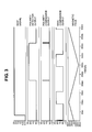
- FIG. 3 depicts simulation results according to an embodiment.
- FIG. 4A depicts a block diagram of circuitry according to an embodiment.
- FIG. 4B depicts a comparator circuit diagram according to an embodiment.
- FIG. 5 depicts a block diagram of circuitry according to an embodiment.
- Embodiments relate to omnipolar magnetic field switches.
- omnipolar behavior is generated in a Hall effect switch by extracting the modulus of the electric signal generated by the Hall transducer and feeding it to a single high-precision comparator, without any sampling or additional number of processing steps.
- the modulus extraction and threshold evaluation can be done in parallel.
- switch 100 comprises a magnetic sensor 102 , a block of switches 104 , a main comparator 106 , a polarity comparator 108 , polarity detector circuitry 110 and an output 112 .
- magnetic sensor 102 is a Hall sensor. In other embodiments, some other appropriate magnetic field sensor or element is used. Sensor 102 senses a magnetic field and converts the sensed magnetic field into a differential electrical signal, which is fed to switches block 104 , which comprises one or more switches. In embodiments, switches block 104 can pass the signal unaltered or invert its sign, as will be discussed herein below.
- comparator 106 From switches block 104 , the signal is fed to main comparator 106 and polarity comparator 108 .
- comparator 106 generates four thresholds of omnipolar behavior: Bop 1 , Brp 1 , Bop 2 and Brp 2 .
- Bop 1 occurs when the output switches from high to low while the magnetic field is positive.
- Brp 1 occurs when the output switches from low to high while the magnetic field is positive.
- Bop 2 occurs when the output switches from high to low while the magnetic field is negative.
- Brp 2 occurs when the output switches from low to high while the magnetic field is negative.
- main comparator 106 is a high-precision comparator with incorporated offset and hysteresis. Offset is defined as (Bop+Brp)/2, and an omnipolar switch has two offsets, one positive and one negative. Ideally, the values are equal. Hysteresis is defined as (Bop ⁇ Brp), and an omnipolar switch again has two which are also equal, ideally.
- Comparator 108 is designated as a polarity comparator and is, in one embodiment, a relatively small-area, low-precision comparator when compared with comparator 106 . Comparator 108 is operable in embodiments to detect a zero-passing of the electric signal. In embodiments, some form of hysteresis is generally required by polarity comparator 108 for noise immunity at the transitions through zero.
- comparator 108 The digital output of comparator 108 is fed to polarity detector circuitry 110 , a digital circuit sensitive only to the positive-to-negative transitions of the electrical signal generated at the output of switches block 104 .
- circuitry 110 When such a transition is detected, circuitry 110 generates a signal that triggers switches block 104 to invert its output signal. Thus, the output signal of switches block 104 would then become positive again. A negative-to-positive transition, however, would not affect polarity detection circuitry 110 .
- comparator 106 can always have a positive signal at its input. This signal is the modulus of the electrical signal generated by sensor 102 .
- Main comparator 106 behaves like a normal comparator in a unipolar switch, but because the modulus of the magnetic signal is present at its input, omnipolar behavior is seen at output 112 .
- FIG. 3 shows the output of switch 100 , main comparator output, toggling high and low when the magnetic signal reaches the positive and negative thresholds of switch 100 . This is enabled by the polarity comparator output toggling the polarity detector output each time the magnetic field crosses zero.
- polarity detection circuitry 110 requires a reset at start-up, and a reset signal in included in FIG. 3 .
- Embodiments provide advantages over conventional solutions. First, less die area is required and current consumption is reduced, at least in part because only a single high-precision comparator 106 is used and polarity comparator 108 does not require high accuracy. Further, all thresholds are symmetrical in embodiments because they are generated in a single comparator. Compared with other conventional solutions, embodiments also offer continuous time evaluation of the magnetic signal, with no extra delay on the signal path to induce omnipolar behavior. Additionally, if polarity detection circuitry 110 is kept in reset mode, switch 100 will behave as a unipolar switch, providing versatility.
- Switch 100 can comprise additional components in other embodiments.
- a bias block can be added to generate reference voltages and currents for other circuitry components.
- An oscillator and sequencer can be required in embodiments if a current spinning technique is used by Hall sensor 102 or to put the switch 100 into a different working mode, e.g., low-power.
- a voltage regulator can supply an internally regulated voltage to the components of switch 100 , such as if high voltage capabilities are required.
- An amplifier can be added if the amplitude of the signal generated by Hall sensor 102 is too small to be processed correctly.
- An output stage can also be added according to the output type desired, such as open-drain, push-pull, and current interface as examples. Embodiments can therefore comprise one, some or all of these and other additional components, as appreciated by those skilled in the art.
- Switch 120 is similar to switch 100 but omits switches 104 and includes a modification to internal connections in comparator 106 to facilitate a direct coupling of polarity detection circuitry 110 to comparator 106 .
- a modified differential stage of comparator 106 according to an embodiment is depicted in FIG. 4B .
- Switch 120 also comprises hysteresis and offset generation circuitry 122 .
- Circuitry 122 generates hysteresis and offset for the output behavior of the chip. Because the signals in comparator 106 are cross-coupled after the input stage, where the hysteresis and offset are added, the latter are generated according to the polarity of the input signal.
- hysteresis and offset generation circuitry 122 can be included in other embodiments, including switches 100 ( FIG. 1) and 130 ( FIG. 5 ).
- the inputs of polarity comparator 108 can be coupled before switches 104 , and the polarity detector 110 can be sensitive to both positive-to-negative and negative-to-positive transitions. This is depicted in circuitry 130 in FIG. 5 .
Abstract
Description
- The invention relates generally to magnetic sensors and more particularly to facilitating omnipolar behavior in magnetic field switches.
- Magnetic field switches, such as Hall effect switches, are a type of magnetic sensor with a digital output that toggles from high to low and from low to high when certain levels of the magnetic field intensity are sensed. Such switches are often used for proximity sensing, and the magnetic field-versus-output voltage characteristics include a certain amount of hysteresis in order to provide noise immunity.
- The output behavior of these switches can be unipolar, bipolar or omnipolar. In unipolar switches, the output is dependent upon both the magnitude of the field and the polarity. For some applications, however, dependence on the polarity is not desired, and omnipolar switches are therefore desired. Conventional omnipolar switches use, for example, two cross-coupled hysteresis comparators with digital processing or other solutions typically requiring multi-step evaluation to create omnipolar behavior. For some applications, such solutions are not appropriate because they are too slow or exhibit other undesirable characteristics.
- Therefore, there is a need for improved omnipolar magnetic field switches.
- Embodiments relate to omnipolar magnetic switches, systems and methods.
- In an embodiment, an omnipolar magnetic switch comprises a magnetic sensor configured to generate an electric signal from a sensed magnetic field; switching circuitry coupled to the magnetic sensor to receive and selectively invert the electric signal; a first comparator coupled to the switching circuitry to receive the electric signal or an inverted electrical signal as input from the switching circuitry and to evaluate an amplitude of the input and toggle high or low when the amplitude passes above a first threshold or below a second threshold; a second comparator coupled to inputs of the first comparator to detect positive-to-negative and negative-to-positive transitions of the electric signal generated by the magnetic sensor; and polarity detection circuitry coupled to the second comparator to detect a positive-to-negative transition and coupled to the switching circuitry to instruct the switching circuitry to selectively invert the electric signal when a positive-to-negative transition is detected.
- In an embodiment, a method of providing an omnipolar magnetic switch comprises sensing a magnetic field signal; converting the magnetic field signal into an electric signal; detecting a positive-to-negative transition of the electric signal; inverting the electric signal upon detection of a positive-to-negative transition; and toggling an output when an amplitude of the electric signal passes above a first threshold or below a second threshold.
- In an embodiment, an omnipolar switch comprises a magnetic sensor; switching circuitry coupled to an output of the magnetic sensor; first comparator circuitry coupled to an output of the switching circuitry; second comparator circuitry coupled to the output of the switching circuitry; polarity detecting circuitry coupled to an output of the second comparator circuitry and to an input of the switching circuitry.
- In an embodiment, an omnipolar magnetic switch comprises a magnetic sensor configured to generate an electric signal from a sensed magnetic field; a first comparator coupled to the magnetic sensor to receive the electric signal and to evaluate an amplitude of the input and toggle high or low when the amplitude passes above a first threshold or below a second threshold; a second comparator coupled to inputs of the first comparator to detect positive-to-negative and negative-to-positive transitions of the electric signal generated by the magnetic sensor; polarity detection circuitry coupled to the second comparator to detect positive-to-negative and negative-to-positive transitions and coupled to the first comparator to instruct the first comparator to selectively invert the electric signal when positive-to-negative and negative-to-positive transitions are detected; and hysteresis and offset generation circuitry coupled between the polarity detection circuitry and the first comparator.
- In an embodiment, a signal modulus extraction circuit comprises an electrical signal generator to generate an electrical signal; switching circuitry coupled to the signal generator to receive and selectively invert the electrical signal; a comparator coupled to an output of the switching circuitry to detect positive-to-negative and negative-to-positive transitions of the electrical signal generated by the electrical signal generator; and polarity detection circuitry coupled to an output of the comparator to instruct the switching circuitry to selectively invert the electrical signal when a positive-to-negative transition is detected.
- In an embodiment, an omnipolar magnetic switch comprises a magnetic sensor configured to generate an electric signal from a sensed magnetic field; switching circuitry coupled to the magnetic sensor to receive and selectively invert the electric signal; a first comparator coupled to the switching circuitry to receive at least one of the electric signal or an inverted electric signal as input from the switching circuitry and to evaluate an amplitude of the input and toggle high or low when the amplitude passes above a first threshold or below a second threshold; a second comparator coupled to the magnetic sensor to receive the electric signal and detect positive-to-negative and negative-to-positive transitions of the electric signal; and polarity detection circuitry coupled to the second comparator to detect positive-to-negative and negative-to-positive transitions and coupled to the switching circuitry to instruct the switching circuitry to selectively invert the electric signal when positive-to-negative and negative-to-positive transitions are detected.
- The invention may be more completely understood in consideration of the following detailed description of various embodiments of the invention in connection with the accompanying drawings, in which:
-
FIG. 1 depicts a block diagram of circuitry according to an embodiment. -
FIG. 2 depicts graphs of unipolar, bipolar and omnipolar behavior according to embodiments. -
FIG. 3 depicts simulation results according to an embodiment. -
FIG. 4A depicts a block diagram of circuitry according to an embodiment. -
FIG. 4B depicts a comparator circuit diagram according to an embodiment. -
FIG. 5 depicts a block diagram of circuitry according to an embodiment. - While the invention is amenable to various modifications and alternative forms, specifics thereof have been shown by way of example in the drawings and will be described in detail. It should be understood, however, that the intention is not to limit the invention to the particular embodiments described. On the contrary, the intention is to cover all modifications, equivalents, and alternatives falling within the spirit and scope of the invention as defined by the appended claims.
- Embodiments relate to omnipolar magnetic field switches. In one embodiment, omnipolar behavior is generated in a Hall effect switch by extracting the modulus of the electric signal generated by the Hall transducer and feeding it to a single high-precision comparator, without any sampling or additional number of processing steps. The modulus extraction and threshold evaluation can be done in parallel.
- Referring to
FIG. 1 , an embodiment of an omnipolarmagnetic switch 100 is depicted. In one embodiment,switch 100 comprises amagnetic sensor 102, a block ofswitches 104, amain comparator 106, apolarity comparator 108,polarity detector circuitry 110 and anoutput 112. - In one embodiment,
magnetic sensor 102 is a Hall sensor. In other embodiments, some other appropriate magnetic field sensor or element is used.Sensor 102 senses a magnetic field and converts the sensed magnetic field into a differential electrical signal, which is fed toswitches block 104, which comprises one or more switches. In embodiments,switches block 104 can pass the signal unaltered or invert its sign, as will be discussed herein below. - From
switches block 104, the signal is fed tomain comparator 106 andpolarity comparator 108. Referring also toFIG. 2 ,comparator 106 generates four thresholds of omnipolar behavior: Bop1, Brp1, Bop2 and Brp2. Within pair Bop1 and Bop2, as well as pair Brp1 and Brp2, each has the same amplitude but opposite signs, with the equality generated by the fact thatcomparator 106 sees only the modulus of the magnetic signal. Bop1 occurs when the output switches from high to low while the magnetic field is positive. Brp1 occurs when the output switches from low to high while the magnetic field is positive. Bop2 occurs when the output switches from high to low while the magnetic field is negative. Brp2 occurs when the output switches from low to high while the magnetic field is negative. - In one embodiment,
main comparator 106 is a high-precision comparator with incorporated offset and hysteresis. Offset is defined as (Bop+Brp)/2, and an omnipolar switch has two offsets, one positive and one negative. Ideally, the values are equal. Hysteresis is defined as (Bop−Brp), and an omnipolar switch again has two which are also equal, ideally. -
Comparator 108 is designated as a polarity comparator and is, in one embodiment, a relatively small-area, low-precision comparator when compared withcomparator 106.Comparator 108 is operable in embodiments to detect a zero-passing of the electric signal. In embodiments, some form of hysteresis is generally required bypolarity comparator 108 for noise immunity at the transitions through zero. - The digital output of
comparator 108 is fed topolarity detector circuitry 110, a digital circuit sensitive only to the positive-to-negative transitions of the electrical signal generated at the output ofswitches block 104. When such a transition is detected,circuitry 110 generates a signal that triggers switchesblock 104 to invert its output signal. Thus, the output signal ofswitches block 104 would then become positive again. A negative-to-positive transition, however, would not affectpolarity detection circuitry 110. - Thereby,
comparator 106 can always have a positive signal at its input. This signal is the modulus of the electrical signal generated bysensor 102.Main comparator 106 behaves like a normal comparator in a unipolar switch, but because the modulus of the magnetic signal is present at its input, omnipolar behavior is seen atoutput 112. - Simulated signal values are depicted in
FIG. 3 , which shows the output ofswitch 100, main comparator output, toggling high and low when the magnetic signal reaches the positive and negative thresholds ofswitch 100. This is enabled by the polarity comparator output toggling the polarity detector output each time the magnetic field crosses zero. In one embodiment,polarity detection circuitry 110 requires a reset at start-up, and a reset signal in included inFIG. 3 . - Embodiments provide advantages over conventional solutions. First, less die area is required and current consumption is reduced, at least in part because only a single high-
precision comparator 106 is used andpolarity comparator 108 does not require high accuracy. Further, all thresholds are symmetrical in embodiments because they are generated in a single comparator. Compared with other conventional solutions, embodiments also offer continuous time evaluation of the magnetic signal, with no extra delay on the signal path to induce omnipolar behavior. Additionally, ifpolarity detection circuitry 110 is kept in reset mode, switch 100 will behave as a unipolar switch, providing versatility. - Switch 100 can comprise additional components in other embodiments. For example, a bias block can be added to generate reference voltages and currents for other circuitry components. An oscillator and sequencer can be required in embodiments if a current spinning technique is used by
Hall sensor 102 or to put theswitch 100 into a different working mode, e.g., low-power. A voltage regulator can supply an internally regulated voltage to the components ofswitch 100, such as if high voltage capabilities are required. An amplifier can be added if the amplitude of the signal generated byHall sensor 102 is too small to be processed correctly. An output stage can also be added according to the output type desired, such as open-drain, push-pull, and current interface as examples. Embodiments can therefore comprise one, some or all of these and other additional components, as appreciated by those skilled in the art. - Another embodiment of a
switch 120 is depicted inFIG. 4A .Switch 120 is similar to switch 100 but omitsswitches 104 and includes a modification to internal connections incomparator 106 to facilitate a direct coupling ofpolarity detection circuitry 110 tocomparator 106. A modified differential stage ofcomparator 106 according to an embodiment is depicted inFIG. 4B . Switch 120 also comprises hysteresis and offsetgeneration circuitry 122.Circuitry 122 generates hysteresis and offset for the output behavior of the chip. Because the signals incomparator 106 are cross-coupled after the input stage, where the hysteresis and offset are added, the latter are generated according to the polarity of the input signal. Although only specifically depicted inFIG. 4A , hysteresis and offsetgeneration circuitry 122 can be included in other embodiments, including switches 100 (FIG. 1) and 130 (FIG. 5 ). - In another embodiment, the inputs of
polarity comparator 108 can be coupled beforeswitches 104, and thepolarity detector 110 can be sensitive to both positive-to-negative and negative-to-positive transitions. This is depicted incircuitry 130 inFIG. 5 . - Various embodiments of systems, devices and methods have been described herein. These embodiments are given only by way of example and are not intended to limit the scope of the invention. It should be appreciated, moreover, that the various features of the embodiments that have been described may be combined in various ways to produce numerous additional embodiments. Moreover, while various materials, dimensions, shapes, configurations and locations, etc. have been described for use with disclosed embodiments, others besides those disclosed may be utilized without exceeding the scope of the invention.
- Persons of ordinary skill in the relevant arts will recognize that the invention may comprise fewer features than illustrated in any individual embodiment described above. The embodiments described herein are not meant to be an exhaustive presentation of the ways in which the various features of the invention may be combined. Accordingly, the embodiments are not mutually exclusive combinations of features; rather, the invention may comprise a combination of different individual features selected from different individual embodiments, as understood by persons of ordinary skill in the art.
- Any incorporation by reference of documents above is limited such that no subject matter is incorporated that is contrary to the explicit disclosure herein. Any incorporation by reference of documents above is further limited such that no claims included in the documents are incorporated by reference herein. Any incorporation by reference of documents above is yet further limited such that any definitions provided in the documents are not incorporated by reference herein unless expressly included herein.
- For purposes of interpreting the claims for the present invention, it is expressly intended that the provisions of
Section 112, sixth paragraph of 35 U.S.C. are not to be invoked unless the specific terms “means for” or “step for” are recited in a claim.
Claims (20)
Priority Applications (3)
| Application Number | Priority Date | Filing Date | Title |
|---|---|---|---|
| US13/076,593 US8669759B2 (en) | 2011-03-31 | 2011-03-31 | Omnipolar magnetic switches |
| CN201210087075.9A CN102739224B (en) | 2011-03-31 | 2012-03-28 | Omnipolare magnetschalter and method for providing same |
| DE102012205091.4A DE102012205091B4 (en) | 2011-03-31 | 2012-03-29 | Omnipolar magnetic switches |
Applications Claiming Priority (1)
| Application Number | Priority Date | Filing Date | Title |
|---|---|---|---|
| US13/076,593 US8669759B2 (en) | 2011-03-31 | 2011-03-31 | Omnipolar magnetic switches |
Publications (2)
| Publication Number | Publication Date |
|---|---|
| US20120249124A1 true US20120249124A1 (en) | 2012-10-04 |
| US8669759B2 US8669759B2 (en) | 2014-03-11 |
Family
ID=46845302
Family Applications (1)
| Application Number | Title | Priority Date | Filing Date |
|---|---|---|---|
| US13/076,593 Active 2032-03-13 US8669759B2 (en) | 2011-03-31 | 2011-03-31 | Omnipolar magnetic switches |
Country Status (3)
| Country | Link |
|---|---|
| US (1) | US8669759B2 (en) |
| CN (1) | CN102739224B (en) |
| DE (1) | DE102012205091B4 (en) |
Cited By (11)
| Publication number | Priority date | Publication date | Assignee | Title |
|---|---|---|---|---|
| US20140139213A1 (en) * | 2012-11-21 | 2014-05-22 | Bryan Cadugan | Systems and Methods for Detection of Magnetic Fields |
| US20140232310A1 (en) * | 2013-02-15 | 2014-08-21 | Magna Closures S.P.A. | System and method for controlling a sinusoidal-drive brushless dc electric motor for an automotive power actuator |
| US20150115946A1 (en) * | 2013-10-29 | 2015-04-30 | Infineon Technologies Ag | Systems and Methods Having Omnipolar Comparators for Magnetic Switches |
| US20160049857A1 (en) * | 2014-08-12 | 2016-02-18 | Yiqiang Jake Zhang | Active switching rectifier employing mosfet and current-based control using a hall-effect switch |
| US20160049856A1 (en) * | 2014-08-12 | 2016-02-18 | Yiqiang Jake Zhang | Active switching rectifier employing mosfet and current-based control using a hall-effect switch |
| US9283864B2 (en) * | 2014-02-21 | 2016-03-15 | Infineon Technologies Ag | Circuit, electric power train and method for charging a battery |
| US20190154864A1 (en) * | 2018-08-22 | 2019-05-23 | Christopher James Hahn | Adjustable Sensitivity Magnet Sensor |
| CN110120803A (en) * | 2018-02-06 | 2019-08-13 | 意瑞半导体(上海)有限公司 | A kind of full pole Hall switch circuit |
| EP3561526A1 (en) * | 2018-04-24 | 2019-10-30 | ABLIC Inc. | Zero cross detection circuit and sensor device |
| EP3564686A1 (en) * | 2018-04-24 | 2019-11-06 | ABLIC Inc. | Zero cross detection circuit and sensor device |
| US10627458B2 (en) * | 2017-09-25 | 2020-04-21 | Allegro Microsystems, Llc | Omnipolar schmitt trigger |
Families Citing this family (2)
| Publication number | Priority date | Publication date | Assignee | Title |
|---|---|---|---|---|
| CN103326702B (en) * | 2013-05-31 | 2015-11-11 | 北京经纬恒润科技有限公司 | A kind of Hall switch circuit |
| WO2023102937A1 (en) * | 2021-12-10 | 2023-06-15 | 上海艾为电子技术股份有限公司 | Omnipolar hall sensing device and control method therefor, electronic device |
Citations (19)
| Publication number | Priority date | Publication date | Assignee | Title |
|---|---|---|---|---|
| US3906486A (en) * | 1972-11-08 | 1975-09-16 | Analog Devices Inc | Bipolar dual-ramp analog-to-digital converter |
| US4413950A (en) * | 1980-09-25 | 1983-11-08 | Facet Enterprises, Incorporated | Hall switch pump |
| US4893027A (en) * | 1986-09-25 | 1990-01-09 | Gebhard Balluff Fabrik Feinmechanischer Erzeugnisse Gmbh & Co. | Proximity switch insensitive to interference fields |
| US5278462A (en) * | 1992-04-24 | 1994-01-11 | Fasco Controls Corporation | Threshold crossover detector with improved digital noise rejection |
| US5306968A (en) * | 1991-10-04 | 1994-04-26 | Nec Corporation | Rectifier circuit not using clock signal |
| US5619137A (en) * | 1996-02-12 | 1997-04-08 | Allegro Microsystems, Inc. | Chopped low power magnetic-field detector with hysteresis memory |
| US5933344A (en) * | 1995-03-20 | 1999-08-03 | Hitachi, Ltd. | Microprocessor having timer circuit generating complementary non-overlapped PWM signals |
| US6346812B1 (en) * | 1997-05-13 | 2002-02-12 | Fast Technology Ag | Conditioner circuit for magnetic field sensor |
| US20030184460A1 (en) * | 2002-03-29 | 2003-10-02 | Johnson Mark B. | Comparator, Analog-to-Digital Converter and Method of Analog-to-Digital Conversion Using Non-Linear Magneto-Electronic Device |
| US7021587B1 (en) * | 2004-01-07 | 2006-04-04 | Trutrak Flight Systems, Inc | Dual channel fail-safe system and method for adjusting aircraft trim |
| US7071640B2 (en) * | 2002-10-21 | 2006-07-04 | Renesas Technology Corporation | Rotation drive control circuit of multiphases direct current motor and the start-up method thereof |
| US20080297082A1 (en) * | 2004-10-14 | 2008-12-04 | Renesas Technology Corp. | Drive control device of motor and a method of start-up |
| US20090009273A1 (en) * | 2007-07-02 | 2009-01-08 | Ming-Hua Ku | Hall Effect Switching Circuit and Controlling Method for same |
| US20100079138A1 (en) * | 2008-09-29 | 2010-04-01 | Paul David | Micro-power magnetic switch |
| US20100117715A1 (en) * | 2008-11-13 | 2010-05-13 | Minoru Ariyama | Sensor circuit |
| CN101825690A (en) * | 2010-05-13 | 2010-09-08 | 上海欣磁电子科技有限公司 | Detection method for all-polarity magnetic field |
| US20110089930A1 (en) * | 2008-06-06 | 2011-04-21 | Continental Teves Ag & Co. Ohg | Method for determining at least one first internal parameter of a sensor |
| US20110216453A1 (en) * | 2010-03-08 | 2011-09-08 | Pass & Seymour, Inc. | Protective device for an electrical supply facility |
| US20120119734A1 (en) * | 2010-11-15 | 2012-05-17 | Samsung Electro-Mechanics Co., Ltd. | Hall integrated circuit using rectifier circuit |
Family Cites Families (2)
| Publication number | Priority date | Publication date | Assignee | Title |
|---|---|---|---|---|
| DE2842998C2 (en) | 1978-10-03 | 1986-09-25 | Robert Bosch Gmbh, 7000 Stuttgart | Device for generating speed-dependent control signals, in particular for ignition systems with a dwell angle control device for internal combustion engines |
| US6356741B1 (en) | 1998-09-18 | 2002-03-12 | Allegro Microsystems, Inc. | Magnetic pole insensitive switch circuit |
-
2011
- 2011-03-31 US US13/076,593 patent/US8669759B2/en active Active
-
2012
- 2012-03-28 CN CN201210087075.9A patent/CN102739224B/en not_active Expired - Fee Related
- 2012-03-29 DE DE102012205091.4A patent/DE102012205091B4/en not_active Expired - Fee Related
Patent Citations (19)
| Publication number | Priority date | Publication date | Assignee | Title |
|---|---|---|---|---|
| US3906486A (en) * | 1972-11-08 | 1975-09-16 | Analog Devices Inc | Bipolar dual-ramp analog-to-digital converter |
| US4413950A (en) * | 1980-09-25 | 1983-11-08 | Facet Enterprises, Incorporated | Hall switch pump |
| US4893027A (en) * | 1986-09-25 | 1990-01-09 | Gebhard Balluff Fabrik Feinmechanischer Erzeugnisse Gmbh & Co. | Proximity switch insensitive to interference fields |
| US5306968A (en) * | 1991-10-04 | 1994-04-26 | Nec Corporation | Rectifier circuit not using clock signal |
| US5278462A (en) * | 1992-04-24 | 1994-01-11 | Fasco Controls Corporation | Threshold crossover detector with improved digital noise rejection |
| US5933344A (en) * | 1995-03-20 | 1999-08-03 | Hitachi, Ltd. | Microprocessor having timer circuit generating complementary non-overlapped PWM signals |
| US5619137A (en) * | 1996-02-12 | 1997-04-08 | Allegro Microsystems, Inc. | Chopped low power magnetic-field detector with hysteresis memory |
| US6346812B1 (en) * | 1997-05-13 | 2002-02-12 | Fast Technology Ag | Conditioner circuit for magnetic field sensor |
| US20030184460A1 (en) * | 2002-03-29 | 2003-10-02 | Johnson Mark B. | Comparator, Analog-to-Digital Converter and Method of Analog-to-Digital Conversion Using Non-Linear Magneto-Electronic Device |
| US7071640B2 (en) * | 2002-10-21 | 2006-07-04 | Renesas Technology Corporation | Rotation drive control circuit of multiphases direct current motor and the start-up method thereof |
| US7021587B1 (en) * | 2004-01-07 | 2006-04-04 | Trutrak Flight Systems, Inc | Dual channel fail-safe system and method for adjusting aircraft trim |
| US20080297082A1 (en) * | 2004-10-14 | 2008-12-04 | Renesas Technology Corp. | Drive control device of motor and a method of start-up |
| US20090009273A1 (en) * | 2007-07-02 | 2009-01-08 | Ming-Hua Ku | Hall Effect Switching Circuit and Controlling Method for same |
| US20110089930A1 (en) * | 2008-06-06 | 2011-04-21 | Continental Teves Ag & Co. Ohg | Method for determining at least one first internal parameter of a sensor |
| US20100079138A1 (en) * | 2008-09-29 | 2010-04-01 | Paul David | Micro-power magnetic switch |
| US20100117715A1 (en) * | 2008-11-13 | 2010-05-13 | Minoru Ariyama | Sensor circuit |
| US20110216453A1 (en) * | 2010-03-08 | 2011-09-08 | Pass & Seymour, Inc. | Protective device for an electrical supply facility |
| CN101825690A (en) * | 2010-05-13 | 2010-09-08 | 上海欣磁电子科技有限公司 | Detection method for all-polarity magnetic field |
| US20120119734A1 (en) * | 2010-11-15 | 2012-05-17 | Samsung Electro-Mechanics Co., Ltd. | Hall integrated circuit using rectifier circuit |
Cited By (21)
| Publication number | Priority date | Publication date | Assignee | Title |
|---|---|---|---|---|
| US9625534B2 (en) * | 2012-11-21 | 2017-04-18 | Allegro Microsystems, Llc | Systems and methods for detection of magnetic fields |
| US20140139213A1 (en) * | 2012-11-21 | 2014-05-22 | Bryan Cadugan | Systems and Methods for Detection of Magnetic Fields |
| US20140232310A1 (en) * | 2013-02-15 | 2014-08-21 | Magna Closures S.P.A. | System and method for controlling a sinusoidal-drive brushless dc electric motor for an automotive power actuator |
| US9876451B2 (en) * | 2013-02-15 | 2018-01-23 | Magna Closures S.P.A. | System and method for controlling a sinusoidal-drive brushless DC electric motor for an automotive power actuator |
| US20150115946A1 (en) * | 2013-10-29 | 2015-04-30 | Infineon Technologies Ag | Systems and Methods Having Omnipolar Comparators for Magnetic Switches |
| US10382024B2 (en) * | 2013-10-29 | 2019-08-13 | Infineon Technologies Ag | Systems and methods having omnipolar comparators for magnetic switches |
| US9341682B2 (en) * | 2013-10-29 | 2016-05-17 | Infineon Technologies Ag | Systems and methods having omnipolar comparators for magnetic switches |
| US20160277009A1 (en) * | 2013-10-29 | 2016-09-22 | Infineon Technologies Ag | Systems and methods having omnipolar comparators for magnetic switches |
| US9283864B2 (en) * | 2014-02-21 | 2016-03-15 | Infineon Technologies Ag | Circuit, electric power train and method for charging a battery |
| US9762139B2 (en) * | 2014-08-12 | 2017-09-12 | Yiqiang Jake Zhang | Active switching rectifier employing MOSFET and current-based control using a hall-effect switch |
| US20160049856A1 (en) * | 2014-08-12 | 2016-02-18 | Yiqiang Jake Zhang | Active switching rectifier employing mosfet and current-based control using a hall-effect switch |
| US9966873B2 (en) * | 2014-08-12 | 2018-05-08 | Yiqiang Jake Zhang | Active switching rectifier employing MOSFET and current-based control using a hall-effect switch |
| US20160049857A1 (en) * | 2014-08-12 | 2016-02-18 | Yiqiang Jake Zhang | Active switching rectifier employing mosfet and current-based control using a hall-effect switch |
| US10627458B2 (en) * | 2017-09-25 | 2020-04-21 | Allegro Microsystems, Llc | Omnipolar schmitt trigger |
| CN110120803A (en) * | 2018-02-06 | 2019-08-13 | 意瑞半导体(上海)有限公司 | A kind of full pole Hall switch circuit |
| EP3561526A1 (en) * | 2018-04-24 | 2019-10-30 | ABLIC Inc. | Zero cross detection circuit and sensor device |
| EP3564686A1 (en) * | 2018-04-24 | 2019-11-06 | ABLIC Inc. | Zero cross detection circuit and sensor device |
| US10908193B2 (en) | 2018-04-24 | 2021-02-02 | Ablic Inc. | Zero cross detection circuit and sensor device |
| US10914610B2 (en) | 2018-04-24 | 2021-02-09 | Ablic Inc. | Zero cross detection circuit and sensor device |
| US20190154864A1 (en) * | 2018-08-22 | 2019-05-23 | Christopher James Hahn | Adjustable Sensitivity Magnet Sensor |
| US10514476B2 (en) * | 2018-08-22 | 2019-12-24 | Christopher James Hahn | Adjustable sensitivity magnet sensor |
Also Published As
| Publication number | Publication date |
|---|---|
| DE102012205091B4 (en) | 2020-12-03 |
| US8669759B2 (en) | 2014-03-11 |
| CN102739224B (en) | 2015-03-25 |
| CN102739224A (en) | 2012-10-17 |
| DE102012205091A1 (en) | 2012-10-04 |
Similar Documents
| Publication | Publication Date | Title |
|---|---|---|
| US8669759B2 (en) | Omnipolar magnetic switches | |
| EP2843435B1 (en) | Sensor device | |
| US9354279B2 (en) | Magnetic sensor device for generating an output in accordance with a magnetic field intensity applied to a magnetoelectric conversion hall effect element | |
| JP4675994B2 (en) | Magnetic sensor and magnetic measurement method | |
| US20100117640A1 (en) | Magnetic sensor circuit | |
| EP2829889B1 (en) | Sensor device | |
| US20130076350A1 (en) | Magnetic sensor device | |
| US10803277B2 (en) | Fingerprint sensing circuit and fingerprint sensing apparatus | |
| CN109541288B (en) | Glitch detection of DC voltage | |
| KR102105034B1 (en) | Magnetic sensor circuit | |
| TWI640794B (en) | Sensor device | |
| KR20100053479A (en) | Magnetic sensor circuit | |
| TW201443465A (en) | Magnetic sensing apparatus | |
| US20120074999A1 (en) | Schmitt trigger circuit operated based on pulse width | |
| US9454174B2 (en) | Power supply voltage monitoring circuit, and electronic circuit including the power supply voltage monitoring circuit | |
| JP2013117473A (en) | Rotation angle signal disconnection detection method and device | |
| US10382024B2 (en) | Systems and methods having omnipolar comparators for magnetic switches | |
| TWI580177B (en) | Operational amplifier | |
| CN104124950B (en) | Reversing the current blocks comparator | |
| CN114280512A (en) | Single Hall sensing device and electronic equipment | |
| CN104569563A (en) | High-speed serial data envelope detector | |
| EP3893393A1 (en) | Peak comparator circuitry | |
| JP5856557B2 (en) | Sensor threshold value determination circuit | |
| US8476934B2 (en) | Circuitry and method for differential signal detection with integrated reference voltage | |
| Tiwari et al. | Low cost low power POR circuit for low voltage sensing using adaptive bulk biasing |
Legal Events
| Date | Code | Title | Description |
|---|---|---|---|
| AS | Assignment |
Owner name: INFINEON TECHNOLOGIES AG, GERMANY Free format text: ASSIGNMENT OF ASSIGNORS INTEREST;ASSIGNOR:IONESCU, MIHAI ALEXANDRU;REEL/FRAME:026085/0816 Effective date: 20110331 |
|
| FEPP | Fee payment procedure |
Free format text: PAYOR NUMBER ASSIGNED (ORIGINAL EVENT CODE: ASPN); ENTITY STATUS OF PATENT OWNER: LARGE ENTITY |
|
| STCF | Information on status: patent grant |
Free format text: PATENTED CASE |
|
| MAFP | Maintenance fee payment |
Free format text: PAYMENT OF MAINTENANCE FEE, 4TH YEAR, LARGE ENTITY (ORIGINAL EVENT CODE: M1551) Year of fee payment: 4 |
|
| MAFP | Maintenance fee payment |
Free format text: PAYMENT OF MAINTENANCE FEE, 8TH YEAR, LARGE ENTITY (ORIGINAL EVENT CODE: M1552); ENTITY STATUS OF PATENT OWNER: LARGE ENTITY Year of fee payment: 8 |