US20120057504A1 - Network exploration method and network exploration apparatus - Google Patents
Network exploration method and network exploration apparatus Download PDFInfo
- Publication number
- US20120057504A1 US20120057504A1 US13/181,858 US201113181858A US2012057504A1 US 20120057504 A1 US20120057504 A1 US 20120057504A1 US 201113181858 A US201113181858 A US 201113181858A US 2012057504 A1 US2012057504 A1 US 2012057504A1
- Authority
- US
- United States
- Prior art keywords
- exploration
- terminal
- network
- terminals
- packet
- Prior art date
- Legal status (The legal status is an assumption and is not a legal conclusion. Google has not performed a legal analysis and makes no representation as to the accuracy of the status listed.)
- Granted
Links
Images

Classifications
-
- H—ELECTRICITY
- H04—ELECTRIC COMMUNICATION TECHNIQUE
- H04L—TRANSMISSION OF DIGITAL INFORMATION, e.g. TELEGRAPHIC COMMUNICATION
- H04L45/00—Routing or path finding of packets in data switching networks
- H04L45/12—Shortest path evaluation
- H04L45/123—Evaluation of link metrics
-
- H—ELECTRICITY
- H04—ELECTRIC COMMUNICATION TECHNIQUE
- H04L—TRANSMISSION OF DIGITAL INFORMATION, e.g. TELEGRAPHIC COMMUNICATION
- H04L45/00—Routing or path finding of packets in data switching networks
- H04L45/20—Hop count for routing purposes, e.g. TTL
-
- H—ELECTRICITY
- H04—ELECTRIC COMMUNICATION TECHNIQUE
- H04L—TRANSMISSION OF DIGITAL INFORMATION, e.g. TELEGRAPHIC COMMUNICATION
- H04L45/00—Routing or path finding of packets in data switching networks
- H04L45/26—Route discovery packet
Definitions
- the embodiments discussed herein are related to a network exploration method and a network exploration apparatus to explore a network to which a plurality of terminals is connected.
- a load to a distribution server in a client-server data distribution system increases as the number of data reception terminals increases.
- a capacity of a distribution server where accesses are concentrated on or a capacity of the network infrastructure needs to be increased.
- the distribution cost increases.
- P2P peer-to-peer
- a terminal that receives data transfers the data to another terminal.
- respective terminals function as relay devices and thereby achieve large-scale broadcast. According to the method, even if the number of terminals increases, a load on a distribution server will not increase much.
- the P2P data distribution may be regarded as data distribution over a logical network (or an overlay network) configured by logical links among terminals without a need to be conscious of the physical network environment. Moreover, in the P2P data distribution, an amount of data traffic that flows over the physical network is determined by a method of coupling terminals over the logical network.
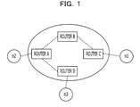
- FIG. 1 illustrates P2P data distribution.
- three terminals, n 1 to n 3 are coupled through routers, A to D.
- data are assumed to be distributed from the terminal n 1 to the terminal n 2 and the terminal n 3 by the P2P method.
- data distribution from the terminal n 1 to the terminal n 2 and the terminal n 3 is achieved, for example, by the following procedure A or procedure B.
- procedure A the terminal n 1 transmits data to the terminal n 2
- the terminal n 2 transfers the data to the terminal n 3 .
- procedure B the terminal n 1 transmits data to the terminal n 3 and the terminal n 3 transfers the data to the terminal n 2 .
- the network distance is represented, for example, by the number of routers over the communication route. For example, in a procedure 1 , three routers, C, B, and A are present over a route from the terminal n 1 to the terminal n 2 while two routers A and D are present over a route from the terminal n 2 to the terminal n 3 . In other words, the total network distance of the procedure 1 is “5.” Meanwhile, in a procedure 2 , four routers, C, B, A, and D are present over a route from the terminal n 1 to the terminal n 3 while two routers D and A are present over a route from the terminal n 3 to the terminal n 2 .
- the total network distance of the procedure 2 is “6.”
- selecting procedure 1 instead of procedure 2 increases efficiency of the data distribution.
- the number of routers over a communication route may be detected, for example, by a traceroute command or a tracert command.
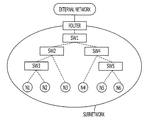
- FIG. 2 illustrates an example of a subnetwork that includes a plurality of switching hubs.
- the subnetwork includes five switching hubs, SW 1 to SW 5 and configured under a control of a router.
- the terminals N 1 to N 6 may transmit and receive data through the switching hubs SW 1 to SW 5 .
- a network topology (a network distance) may be identified in the same manner as the network configured by routers in FIG. 1 may be identified.
- data are assumed to be transmitted from the terminal N 1 to terminals, N 2 to N 6 by the P2P method.
- the terminal N 1 transmits data to a destination terminal with substantially the shortest network distance.
- the terminal N 1 transmits data to the terminal N 2 .
- the terminal N 2 transfers the received data to another destination terminal with substantially the shortest network distance.
- terminal N 2 transfers the data to the terminal N 3 .
- each terminal transfers the received data to another terminal based on the network distance. Accordingly, efficient data distribution from the terminal N 1 to terminals, N 2 to N 6 may be achieved.
- Japanese Laid-open Patent Publication No. 2000-172600 discusses a network configuration exploration method that is capable of identifying devices to be managed that are connected to a network using different protocols.
- types of protocols that can be used are obtained and exploration requests are transmitted that request devices coupled using all types of protocols to respond. Then responses from the devices are calculated and a device list used for managing the devices is displayed based on the calculated result.
- Japanese Laid-open Patent Publication No. 2006-345347 discusses a communication apparatus that performs configuration exploration of a customer premises network.
- the communication apparatus includes an exploration packet generation unit, a received packet analysis unit, a control unit, and a packet transmission and reception unit.
- the exploration packet generation unit generates a router exploration packet in which time to live (TTL) is changed and switches a transmission destination of the router exploration packet.
- the received packet analysis unit obtains an address of the router from an Internet Control Message Protocol (ICMP) packet that is returned from the router in response to the router exploration packet.
- ICMP Internet Control Message Protocol
- the control unit obtains information from the received packet analysis unit, controls the router exploration packet generation unit, and conducts the network exploration.
- the packet transmission and reception unit transmits and receives the router exploration packet and the ICMP packet.
- a network exploration apparatus is configured to calculate a communication cost of a network to which a plurality of terminals is coupled through a plurality of network devices, the network exploration apparatus including: a transmitter configured to transmit an exploration packet to the plurality of terminals; a receiver configured to receive a response packet for the exploration packet; a detector configured to detect a terminal group to which a terminal that does not receive the exploration packet among the plurality of terminals belongs based on a reception result of the response packet by the receiver; and a calculator configured to calculate a communication cost between terminals based on an inclusion relationship between a plurality of terminal groups detected by the detector when the transmitter repeatedly transmits the exploration packet.
- FIG. 1 illustrates P2P data distribution
- FIG. 2 illustrates an example of a subnetwork that includes a plurality of switching hubs
- FIG. 3 illustrates a configuration example of a network in which a network exploration method according to an embodiment is used
- FIG. 4 illustrates a configuration of a network exploration apparatus
- FIG. 5A is an embodiment of an exploration packet
- FIG. 5B is an embodiment of a response packet
- FIG. 6A is an embodiment of a temporary list
- FIG. 6B is an embodiment of a terminal list
- FIG. 7A illustrates a method to detect a terminal group
- FIG. 7B illustrates a method to detect a terminal group
- FIG. 8 is an embodiment of a group information list
- FIG. 9 is a flow chart illustrating processing to create a group information list
- FIG. 10 is a flow chart illustrating processing to aggregate terminal groups
- FIG. 11A illustrates a case when an inclusion relationship among terminal groups contradicts
- FIG. 11B illustrates a case when an inclusion relationship among terminal groups contradicts
- FIG. 11C illustrates a case when an inclusion relationship among terminal groups contradicts
- FIG. 12 is a flow chart illustrating processing to calculate a communication cost
- FIG. 13 is an embodiment of a communication cost table
- FIG. 14 is an example of a network configuration in which a network exploration method according to another embodiment is used.
- FIG. 15 is an embodiment of a communication cost table created by another embodiment.
- FIG. 16 illustrates a hardware configuration of a network exploration apparatus.
- L2 Layer 2
- OSI Open Systems Interconnection
- the L2 switch transfers the data based on destination information of the data, however the L2 switch may not process a command (for example, a trace route command) of an IP layer or a higher layer.
- a command for example, a trace route command
- communication terminals for example, terminals, L2 switches, and a network management device
- measuring a network distance between terminals is difficult.
- each terminal may not appropriately select a destination terminal with a shorter network distance in the network and data are inefficiently distributed.
- the present disclosure achieves a mechanism capable of estimating a communication cost in order to improve communication efficiency among terminals in a network to which a plurality of terminals is coupled.
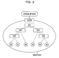
- FIG. 3 illustrates a configuration example of a network in which a network exploration method according to an embodiment is used.
- a network exploration method according to the embodiment is used in a subnetwork 2 that is coupled to a router 1 .
- the router 1 couples an external network 3 with the subnetwork 2 .
- the router 1 in the example provides functions of the layer 3 or higher of the OSI reference model, and for example, provides a function to respond to a trace route command, etc.
- the subnetwork 2 is configured with a plurality of network devices (according to the embodiment, switching hubs SW 1 to SW 5 ).
- the switching hub SW 1 is coupled to the router 1 .
- the switching hub SW 2 and the switching hub SW 4 are coupled to the switching hub SW 1 .
- the switching hub SW 3 is coupled to the switching hub SW 2 and the switching hub SW 5 is coupled to the switching hub SW 4 .
- the switching hubs SW 1 to SW 5 are, for example, L2 switches. In other words, it is assumed that the switching hubs SW 1 to SW 5 in this example may not execute an IP command and a protocol command of the layer 3 or higher.
- the terminal N 1 to N 6 are coupled to the subnetwork 2 .
- the terminal N 1 and the terminal N 2 are accommodated in the switching hub SW 3 .
- the terminal N 3 is accommodated in the switching hub SW 2 .
- the terminal N 4 is accommodated in the switching hub SW 4 .
- the terminal N 5 and the terminal N 6 are accommodated in the switching hub SW 5 .
- Each of the terminals N 1 to N 6 has a function to transmit and receive data to and from another terminal by peer-to-peer (P2P).
- Destination information to achieve broadcast by P2P is set in each of the terminals N 1 to N 6 .
- destination information of N 1 , N 2 , N 3 , N 4 , N 5 , and N 6 other than that of own terminal is set in the terminals N 1 , N 2 , N 3 , N 4 , N 5 , and N 6 respectively.
- the router 1 transfers broadcast data addressed to the terminal N 1 that is received from the external network 3 to the terminal N 1 by way of the SW 1 , SW 2 , and SW 3 .
- the terminal N 1 refers to destination information and transfers the broadcast data received from the external network 3 to the terminal N 2 via the SW 3 .
- the terminal N 2 refers to the destination information and transfers the broadcast data received from the terminal N 1 to the terminal N 3 by way of SW 3 and SW 2 .
- the terminals N 3 , N 4 , and N 5 transfer the broadcast data to the terminals N 4 , N 5 , and N 6 respectively via SWs according to the destination information. Accordingly, the terminals N 1 to N 6 receive the broadcast data.
- the terminal N 6 may further transfer the received broadcast data to other terminal in another subnetwork.
- a network exploration apparatus 10 is a server computer, detects a topology of the subnetwork 2 , and calculates communication costs among the terminals N 1 to N 6 .
- the communication cost corresponds to the number of switching hubs that are present over a communication route among terminals.
- a network exploration apparatus 10 may generate the above-described destination information based on communication costs among the terminals N 1 to N 6 . In this case, the destination information is determined so as to substantially optimize communication efficiency of the above-described broadcast distribution.
- the network exploration apparatus 10 may distribute destination information to the terminals N 1 to N 6 .
- the terminals N 1 to N 6 may request corresponding destination information to the network exploration apparatus 10 .
- the network exploration apparatus 10 is coupled to the switching hub SW 1 .
- the network exploration apparatus 10 may be coupled to any of the switching hubs SW 2 to SW 5 .
- the network exploration apparatus 10 may be coupled to the router 1 or may be provided over the external network 3 .
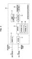
- FIG. 4 illustrates a configuration of the network exploration apparatus 10 .
- the network exploration apparatus 10 includes a transmitter 11 , a receiver 12 , a detector 13 , and a calculator 14 .
- the transmitter 11 transmits exploration packets to all terminals coupled to a network to be explored. In the example of FIG. 3 , the transmitter 11 transmits exploration packets to each of the terminals N 1 to N 6 that are coupled to the subnetwork 2 .
- the transmitter 11 transmits exploration packets by IP multicast or broadcast, although the embodiment is not limited to this.
- an IP multicast address for example, “224.0.0.1”
- the terminals N 1 to N 6 are set so as to receive exploration packets of the IP multicast address.
- the switching hubs SW 1 to SW 5 in FIG. 3 transfer exploration packets transmitted from the network exploration apparatus 10 to the terminals N 1 to N 6 according to the multicast address.
- exploration packets transmitted from the network exploration apparatus 10 are transferred to the router 1 as well.
- the router 1 is set so as not to transmit the received exploration packets to an external network 2 , although the embodiment is not limited to this.
- the transmitter 11 transmits an exploration packet by a protocol without a retransmission function, although the embodiment is not limited to this.
- the transmitter 11 transmits an exploration packet, for example, by User Datagram Protocol (UDP).
- UDP User Datagram Protocol
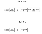
- an ID, an exploration number, a return address, and a return port are set in an exploration packet.
- the ID indicates a packet type.
- a certain value indicating an exploration packet is set in an ID field of an exploration packet.
- the exploration number corresponds to a sequence number to identify each transmission procedure when the network exploration apparatus 10 repeats procedure to transmit exploration packets to the terminals N 1 to N 6 . Accordingly, the same exploration number is assigned to each exploration packet transmitted to the terminals N 1 to N 6 by multicast or broadcast at one time.
- the return address and the return port represent an address indicating destination to which the terminal that receives the exploration packet returns a response packet and the TCP/IP port number respectively.
- an IP address of the network exploration apparatus 10 is set in the return address.
- a reserved port number to receive a response packet at the network exploration apparatus 10 is set in the return port.
- each of the terminals N 1 to N 6 When each of the terminals N 1 to N 6 receives the above-described exploration packet, creates a response packet illustrated in FIG. 5B and returns the response packet to the network exploration apparatus 10 . At this time, each of the terminals N 1 to N 6 transmits a response packet by a protocol with a retransmission function, although the embodiment is not limited to this. In other words, each of the terminals N 1 to N 6 transmits a response packet, for example, by Transmission Control Protocol (TCP).
- TCP Transmission Control Protocol
- the “return address” notified by an exploration packet is set in the destination IP address of the IP header of the response packet.
- the destination IP address of the response packet is an IP address of the network exploration apparatus 10 .
- the “return port” that is notified by an exploration packet is set in the destination port number of the TCP header of the response packet.
- a certain value that indicates the response packet is set in the ID field of the response packet.
- An exploration number of the received exploration packet is used as it is for the exploration number set in the response packet.
- the switching hubs SW 1 to SW 5 transfer the response packets transmitted from the terminals N 1 to N 6 to the network exploration apparatus 10 .
- the response packet includes information to identify a transmission source terminal of the response packet.
- the information to identify a transmission source terminal is, for example, a transmission source IP address set in an IP header. Accordingly, the network exploration apparatus 10 may detect the transmission source terminal of the response packet.
- the receiver 12 receives a response packet for the exploration packet transmitted from the transmitter 11 .
- the receiver 12 waits for response packets to be transmitted from the terminals N 1 to N 6 at a TCP port indicated by the above-described “return port.”
- the receiver 12 passes the response packets received from the terminals N 1 to N 6 to the detector 13 .
- the receiver 12 waits for response packets for the exploration packet typically for a time period until a certain time AT elapses from when the transmitter 11 transmits the exploration packets.
- the receiver 12 waits for a response packet to which the exploration number 001 is set until time T 1 + ⁇ T. Subsequently, when the transmitter 11 transmits an exploration packet to which an exploration number 002 is set at time T 2 , the receiver 12 waits for the response packet in which the exploration number 002 is set until time T 2 + ⁇ T.
- the exploration number set in the exploration packet and transmission time of the exploration packet are notified, for example, from the transmitter 11 to the receiver 12 .
- the detector 13 may manage exploration numbers. In this case, the exploration number is notified from the detector 13 to the transmitter 11 and the receiver 12 .
- the detector 13 detects a terminal group to which a terminal that does not receive the exploration packet belongs among all of the terminals coupled to the network to be explored based on the reception result of the exploration packet by the receiver 12 . In other words, the detector 13 detects a terminal group to which a terminal that does not receive the exploration packet belongs among the terminals N 1 to N 6 . The detector 13 detects the terminal group by using the temporary list 15 and the terminal list 16 . The temporary list 15 and the terminal list 16 may be provided in the detector 13 or outside of the detector 13 . The detector 13 detects a terminal group for each exploration number (in other words, whenever exploration packets are transmitted to the terminals N 1 to N 6 by multicast or broadcast).
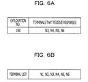
- FIG. 6A is an embodiment of the temporary list 15 .
- a transmission source terminal of a response packet is registered in the temporary list 15 for each exploration number.
- the detector 13 checks an exploration number and a transmission source terminal of a response packet received by the receiver 12 .
- the transmission source terminal of the response packet is identified, for example, by a transmission source IP address set in the IP header.
- the detector 13 registers a transmission source terminal of a received response packet in the temporary list 15 whenever the receiver 12 receives a response packet.
- the example of FIG. 6A illustrates a state of the temporary list 15 when the transmitter 11 transmits exploration packets with an exploration number 100 to the terminals N 1 to N 6 and the receiver 12 receives response packets for the exploration packets from the terminals N 3 , N 4 , N 5 , and N 6 .
- FIG. 6B is an embodiment of the terminal list 16 .
- Terminals coupled to a network to be explored are registered in the terminal list 16 .
- the terminals N 1 , N 2 , N 3 , N 4 , N 5 , and N 6 that are coupled to the subnetwork 2 are registered in the terminal list 16 .
- the terminal list 16 is prepared beforehand.
- terminals to be coupled to a network to be explored are unknown, the terminal list 16 is created, for example, by the following procedure A:
- (a1) transmit an exploration packet by multicast or broadcast.
- the detector 13 may detect a terminal group while creating the terminal list 16 at the above procedure (a1) to (a5). Alternatively, the detector 13 may detect a terminal group after creating the terminal list 16 at the procedure (a1) to (a5).
- the detector 13 detects a terminal group by the following procedure B:
- (b1) instruct the transmitter 11 to transmit an exploration packet. Accordingly, the transmitter 11 transmits exploration packets to the terminals N 1 to N 6 by multicast or broadcast. At this time, the exploration packets are transmitted basically to all terminals registered in the terminal list 16 .
- (b2) register transmission source terminals of response packets (in other words, a response packet with an exploration number “i”) corresponding to the exploration packets transmitted at (b1) in the temporary list 15 .
- (b3) refer to the temporary list 15 and the terminal list 16 and detect a terminal that is registered in the terminal list 16 but not registered in the temporary list 15 .
- the detected one or more terminals are “a terminal other than the transmission source terminal of the response packet”
- (b4) output a terminal group elements of which are the one or more terminals detected at (b3) as a terminal group obtained for an exploration number “i.”
- the detector 13 detects the terminal group elements of which are “a terminal other than the transmission source terminal of the response packet” for the exploration number “i.”
- the terminals N 1 to N 6 are registered in the terminal list 16
- the terminals N 3 to N 6 are registered in the temporary list 15 for the exploration number 100 .
- the terminals N 1 and N 2 are registered in the terminal list 16 but not registered in the temporary list 15 .
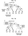
- FIG. 7 illustrates a method to detect a terminal group.
- the network exploration apparatus 10 transmits exploration packets to the terminals N 1 to N 6 by multicast or broadcast.
- the exploration packets basically reach all of the terminals N 1 to N 6 .
- packets transmitted through a network may be discarded, for example, when the network is congested. In other words, packet loss of exploration packets transmitted from the network exploration apparatus 10 to the terminals N 1 to N 6 may be caused over the network.
- congestion is caused at the switching hub SW 3 , and the exploration packet is discarded at the switching hub SW 3 .
- exploration packets transmitted from the network exploration apparatus 10 reach the terminals N 3 to N 6 , however do not reach the terminals N 1 to N 2 .
- the exploration packets according to the embodiment are transmitted by a protocol without a retransmission function. Accordingly, when a packet loss is caused at the switching hub SW 3 , the terminals N 1 to N 2 do not receive the above described exploration packets.
- the terminals N 3 to N 6 When the terminals N 3 to N 6 receive the exploration packets, the terminals N 3 to N 6 create corresponding response packets and return the response packets to the network exploration apparatus 10 respectively. At this time, the response packets are transmitted by a protocol with a retransmission function. Hence, the response packets transmitted from the terminals N 3 to N 6 surely reach the network exploration apparatus 10 even if the subnetwork 2 is congested. In other words, the network exploration apparatus 10 receives the response packets from the terminals N 3 to N 6 .
- the terminals N 1 and N 2 in the example do not receive exploration packets; thereby neither of the terminals N 1 to N 2 transmits a response packet. Accordingly, the network exploration apparatus 10 does not receive any response packet from the terminals N 1 and N 2 .
- the detector 13 of the network exploration apparatus 10 groups the terminals N 1 and N 2 if the detector 13 may not receive response packets from the terminals N 1 and N 2 within a certain time period. In other words, a terminal group, “N 1 , N 2 ” is detected.
- a terminal that receives an exploration packet returns a response packet to the network exploration apparatus 10 .
- the response packet transmitted by the terminal surely reaches the network exploration apparatus 10 as described above. Accordingly, a cause that the network exploration apparatus 10 may not receive the response packets from the terminals N 1 and N 2 is considered that the exploration packets do not reach the terminals N 1 and N 2 .
- terminals other than a transmission source terminal of the response packet do not receive the exploration packets and the terminal N 1 and N 2 are grouped as “terminals that may not receive exploration packets.”
- a cause that exploration packets do not reach the terminal N 1 and N 2 is that the exploration packets may be discarded at a network device (according to the embodiment, a switching hub SW 3 ) related to both the terminals N 1 and N 2 .
- the terminal group detected as described above may be used as information that indicates a network topology.
- the terminals N 1 and N 2 are coupled to the same switching hub, or the terminals N 1 and N 2 are coupled to the same switching hub viewed from the network exploration apparatus 10 .
- both the terminals N 1 and N 2 are coupled to the switching hub SW 3 .
- congestion is caused at the switching hub SW 4 and exploration packets are discarded at the switching hub SW 4 .
- exploration packets transmitted from the network exploration apparatus 10 reach the terminals N 1 to N 3 ; however do not reach the terminals N 4 to N 6 .
- the network exploration apparatus 10 receives response packets from the terminals N 1 to N 3 , however do not receive response packets from the terminals N 4 to N 6 .
- the detector 13 groups the terminals N 4 , N 5 , and N 6 . In other words, a terminal group “N 4 , N 5 , and N 6 ” is detected.
- the exploration packets are considered to be discarded with a high possibility at a network device (according to the embodiment, the switching hub SW 4 ) that is commonly related to in the terminals N 4 , N 5 , and N 6 .
- the terminals N 4 , N 5 , and N 6 are coupled to the same switching hub, or the terminals N 4 , N 5 , and N 6 are coupled to the same switching hub viewed from the network exploration apparatus 10 .
- all of the terminals N 4 , N 5 , and N 6 are coupled to the switching hub SW 4 viewed from the network exploration apparatus 10 .
- the network exploration apparatus 10 repeatedly executes the above-described exploration.
- the “exploration” corresponds to a procedure that transmits exploration packets to all terminals coupled to the subnetwork 2 and monitors the responses.
- the detector 13 detects a plurality of terminal groups according to whether a response packet for each exploration may be received from each terminal.
- the terminal groups detected by the detector 13 are notified to the calculator 14 .
- the calculator 14 calculates a communication cost between terminals based on an inclusion relationship among the plurality of terminal groups detected by the detector 13 .
- the calculator 14 calculates the communication cost between terminals while updating and referring to a group information list 17 .
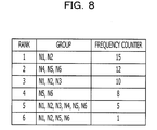
- FIG. 8 is an embodiment of the group information list 17 .
- a terminal group detected by the detector 13 is registered in the group information list 17 .
- the following six terminal groups are registered in the group information list 17 .
- the six groups are “N 1 , N 2 ”, “N 4 , N 5 , N 6 ”, “N 1 , N 2 , N 3 ”, “N 5 , N 6 ”, “N 1 , N 2 , N 3 , N 4 , N 5 , N 6 ”, and “N 1 , N 2 , N 5 , N 6 .”
- the terminal group, “N 1 , N 2 ” is registered when the network exploration apparatus 10 may not receive response packets from the terminals N 1 and N 2 .
- the terminal group, “N 4 , N 5 , N 6 ” is registered when the network exploration apparatus 10 may not receive response packets from the terminals N 4 , N 5 , and N 6 .
- the group information list 17 manages a detection frequency of each terminal group (a frequency counter in FIG. 8 ).
- the detection frequency in the example indicates the number of times a terminal group is detected by the detector 13 .
- the calculator 14 counts up a frequency counter of a terminal group when the detector 13 detects the terminal group.
- the terminal group, “N 1 , N 2 ” is detected at 15 times and the terminal group, “N 4 , N 6 ” is detected at 12 times.
- the calculator 14 sorts terminal groups registered in the group information list 17 according to the detection frequencies.
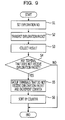
- FIG. 9 is a flow chart illustrating processing to create the group information list 17 .
- the processing is executed by the transmitter 11 , the receiver 12 , the detector 13 , and the calculator 14 .
- the execution of processing is, for example, repeated periodically.
- the detector 13 sets an exploration number at operation S 1 .
- the exploration number is, for example, a sequence number and different values are used for respective explorations.
- the “exploration” corresponds to a procedure to transmit exploration packets to all terminals coupled to the subnetwork 2 and detects the responses.
- the detector 13 notifies an exploration number to the transmitter 11 and the receiver 12 .
- the detector 13 generates exploration numbers; however other circuit components may generate exploration numbers.
- the transmitter 11 creates exploration packets and transmits the exploration packets to all terminals coupled to the subnetwork 2 .
- the exploration number notified by the detector 13 is set in the exploration packet.
- the exploration packets are transmitted by multicast or broadcast.
- the receiver 12 and the detector 13 collect exploration results.
- the receiver 12 waits for a response packet in which an exploration number notified by the detector 13 is set until a certain time period elapses from when the transmitter 11 transmits the exploration packets.
- the detector 13 compares a transmission source terminal of each response packet received by the receiver 12 with terminals registered in the terminal list 16 . It is considered that the transmission source terminal of the response packet receives the exploration packet while other terminals do not receive exploration packets. In other words, a terminal that does not receive an exploration packet is detected.
- the detector 13 determines whether there is any terminal that does not receive an exploration packet based on a reception state of the response packets. If there is any terminal that does not receive an exploration packet, the processing proceeds to operation S 5 . When the receiver 12 receives response packets from all of the terminals, the processing is completed.
- the detector 13 groups terminals that do not receive exploration packets.
- the calculator 14 increments a frequency counter (counts up a count value for 1) of the terminal group detected by the detector 13 in the group information list 17 .
- the calculator 14 sorts the updated group information list 17 according to the value of the frequency counter.
- the network exploration apparatus 10 creates the group information list 17 by repeatedly executing processing of the flow chart in FIG. 9 .
- the processing of operations S 5 to S 6 are executed basically when an exploration packet transmitted by the network exploration apparatus 10 is discarded at any of the switching hubs in the subnetwork 2 .
- the group information list 17 is updated basically when an exploration packet is discarded.
- the calculator 14 executes aggregation of terminal groups by using the group information list 17 created as described above.
- the aggregation of the terminal groups corresponds to processing to detect a topology of a network to be explored.
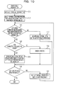
- FIG. 10 is a flow chart illustrating processing to aggregate terminal groups. The processing of the flow chart is executed, for example, by the calculator 14 after the group information list 17 is created.
- the calculator 14 initializes topology information.
- the topology information is created in a certain memory area (not illustrated) in the network exploration apparatus 10 .
- the calculator 14 selects a terminal group with substantially the largest frequency counter value in the group information list 17 . It is assumed that terminal groups are sorted according to values of the frequency counters in the group information list 17 .
- the calculator 14 determines whether there is any common element between processing target group information and the topology information.
- the processing target group information indicates one or a plurality of terminal groups that belongs to the terminal group selected at operations S 12 or S 19 .
- the topology information indicates a relationship between terminals and will be described later by referring to an embodiment.
- the topology information does not include any element at operation S 11 when the topology information is initialized.
- the topology information is updated at Operation S 14 or Operation S 16 . If there is any common element (in other words, a terminal ID) between the processing target group information and the topology information, the processing proceeds to operation S 14 , and otherwise the processing proceeds to operation S 17 .
- the calculator 14 detects whether there is any inclusion relationship between processing target group information and each section list in the topology information.
- each section list will be described later by referring to an embodiment, and includes one or more terminal IDs.
- processing target group information is “N 1 , N 2 ” and a section list in the topology information is “(N 1 , N 2 , and N 3 )”.
- the section list is determined to include the processing target group information.
- processing target group information is “N 1 , N 2 ” and a section list in the topology information is “(N 2 , and N 3 )”.
- N 1 that belongs to the processing target group information is not an element of the section list and “N 3 ” that belongs to the section list is not an element of the processing target group information. Thus, it is determined that there is no inclusion relationship between the processing target group information and the topology information.
- the calculator 14 updates the topology information at operation S 15 .
- the section list having the inclusion relationship with the processing target group information is replaced with an inclusion list that indicates the inclusion relationship between the processing target group information and the topology information.
- the calculator 14 determines that the processing target group information includes an error at step 16 . In this case, the processing of operation S 15 is skipped. Moreover, the processing target group information is discarded.
- the calculator 14 adds a terminal list represented by the processing target group information to the topology information as a new section list at operation S 17 . In this case, the processing of operation S 15 is also skipped.
- the calculator 14 checks whether all of the terminal groups registered in the group information list 17 are selected. If there is any unselected terminal group in the group information list 17 , the calculator 14 selects the next terminal group and returns to operation S 13 . In other words, the calculator 14 sequentially selects terminal groups one by one from the group information list 17 according to the frequency counters and executes processing of operations S 13 to S 19 respectively. Accordingly, the terminal groups are aggregated and the topology information is generated.
- a terminal group with substantially the largest frequency counter value is selected from the group information list 17 in FIG. 8 .
- the terminal group, “N 1 , N 2 ” is selected.
- no common element is present between the processing target group information and the topology information because the topology information is initialized, and thereby operation S 13 is determined to be “No.” Therefore, at operation S 17 , the terminal group, “N 1 , N 2 ” is added to the topology information as one section list.
- the parenthesis in the notation of the topology information indicates a terminal group. In other words, the plurality of terminals in one parenthesis indicates that the terminals belong to the same terminal group.
- the terminal group with the second highest frequency is selected.
- the terminal group, “N 4 , N 5 , N 6 ” is selected.
- No common element is present between the selected terminal group “N 4 , N 5 , N 6 ” and the topology information 1 “(N 1 , N 2 ).”
- the terminal group, “N 4 , N 5 , N 6 ” is added to the topology information as a new section list.
- the third terminal group, “N 1 , N 2 , N 3 ” is selected. There are common elements between the selected terminal group, “N 1 , N 2 , N 3 ” and the topology information 2 “(N 1 , N 2 ) (N 4 , N 5 , N 6 ).” Moreover, an inclusion relationship is present between the selected terminal group, “N 1 , N 2 , N 3 ” and a section list of the topology information 2 “(N 1 , N 2 ).” In other words, each of the elements in the section list “(N 1 , N 2 )” is included in the elements of the terminal group “N 1 , N 2 , N 3 .” Hence, in this case, an inclusion list “((N 1 , N 2 ), N 3 )” that indicates the inclusion relationship is created at operation S 15 .
- the section list “(N 1 , N 2 )” having an inclusion relationship with the processing target group information is replaced with the inclusion list “((N 1 , N 2 ), N 3 )” that indicates the inclusion relationship between the processing target group information and the topology information.
- the topology information is updated as follows:
- Topology information 3 ((N 1 , N 2 ) N 3 ) (N 4 , N 5 , N 6 )
- the multiple parentheses indicate the terminal groups have a parent and child relationship. For example, “((N 1 , N 2 ) N 3 )” indicates a child terminal group “N 1 , N 2 ” is present in the terminal group, “(N 1 , N 2 ) N 3 .”
- the fourth terminal group “N 5 , N 6 ” is selected.
- common elements are present between the selected terminal group, “N 5 , N 6 ” and the topology information 3 , ((N 1 , N 2 ) N 3 ) (N 4 , N 5 , N 6 ).
- an inclusion relationship is present between the selected terminal group, “N 5 , N 6 ” and a section list of the topology information 3 “(N 4 , N 5 , N 6 ).”
- each of the elements in the section list “(N 5 , N 6 )” is included in the elements of the section list “(N 4 , N 5 , N 6 ).” Therefore, the inclusion list (N 4 , (N 5 , N 6 )) that indicates the inclusion relationship is created at operation S 15 .
- the section list “(N 4 , N 5 , N 6 )” of the topology information 3 is replaced with the inclusion list, “(N 4 , (N 5 , N 6 )).”
- the topology information is updated as follows:
- Topology information 4 ((N 1 , N 2 ) N 3 ) (N 4 (N 5 , N 6 ))
- the topology information is updated in the same manner as follows:
- Topology information 5 ((N 1 , N 2 ) N 3 ) (N 4 (N 5 , N 6 ))
- the sixth terminal group, “N 1 , N 2 , N 5 , N 6 ” is selected. Common elements are present between the selected terminal group, “N 1 , N 2 , N 5 , N 6 ” and the topology information 5 “((N 1 , N 2 ) N 3 ) (N 4 (N 5 , N 6 )).” However, no inclusion relationship is present between the selected terminal group, “N 1 , N 2 , N 5 , N 6 ” and each of the section lists of the topology information 5 .
- the topology information 5 includes the section list 1 “(((N 1 , N 2 ) N 3 ))”, and the section list 2 “(N 4 (N 5 , N 6 )).”
- N 3 that belongs to the section list 1 does not belong to the above-described terminal group
- N 5 and N 6 that belong to the above-described terminal list do not belong to the section list 1 .
- operation S 14 determined to be “No”.
- operation S 16 an error is detected.
- the calculator 14 When operations S 13 to S 17 are executed for all of the terminal groups registered in the group information list 17 as described above, the calculator 14 outputs the created topology information. In the above example, the calculator 14 outputs the topology information 5 .
- the calculator 14 creates and outputs topology information by executing operations S 13 to S 17 for each terminal group registered in the group information list 17 .
- topology information may be created by executing operations S 13 to S 17 for some of the terminal groups registered in the group information list 17 .
- operations S 13 to S 17 may be executed for a terminal group the frequency counter value of which exceeds a certain threshold.
- the threshold may be determined, for example, by the number of terminals coupled to a network to be explored, and/or the number of times to execute explorations. In the example of FIG. 8 , the threshold is assumed to be “6”, for example. Processing of operations S 13 to S 17 is executed for the top 4 terminal groups and the above-described topology information 4 is output.
- the calculator 14 may end the aggregation processing of the terminal groups if operation S 14 is determined to be “No” and an error is detected. In other words, aggregation processing of the terminal groups may be ended if any contradiction is caused in the inclusion relationship between previously selected terminal groups and a newly selected terminal group.
- a case is described in which an inclusion relationship between terminal groups contradicts and an error is detected at operation S 16 . It is assumed as an example that two terminal groups “N 1 , N 2 ” and “N 2 , N 3 ” are detected and registered in the group information list 17 .
- the terminal group “N 1 , N 2 ” is detected when “the terminal N 3 receives an exploration packet, however the terminals N 1 and N 2 do not receive exploration packets.” In other words, the terminal group “N 1 , N 2 ” is detected, for example, when a loss of an exploration packet is caused at a switching hub SW-X in a network topology illustrated in FIG. 11A .
- the terminal group “N 2 , N 3 ” is detected when “the terminal N 1 receives an exploration packet, however, the terminals N 2 and N 3 do not receive exploration packets.”
- the terminal group “N 2 , N 3 ” is detected, for example, when a loss of an exploration packet is caused at a switching hub SW-Y in a network topology illustrated in FIG. 11B .
- the network exploration method estimates a network topology based on a terminal group with a higher detection frequency when terminal groups that contradict each other are detected.
- processing of the flow chart in FIG. 10 is executed for terminal groups in order of a terminal group with a greater frequency counter value. If an inclusion relationship between the previously selected terminal group and newly selected terminal group contradicts, group information of the newly selected terminal group is ignored in the flow chart in FIG. 10 .
- a network topology in FIG. 11A is estimated when the detection frequency of the terminal group “N 1 , N 2 ” is higher than that of the terminal group “N 2 , N 3 .”
- a state that the terminal group “N 2 , N 3 ” is detected in the network topology illustrated in FIG. 11A is when packet losses are caused at two points as illustrated in FIG. 11C .
- the terminal group “N 2 , N 3 ” is detected when a packet loss of an exploration packet is caused at a switching hub SW-W provided between the switching hub SW-X and the terminal N 2 , and a packet loss of an exploration packet is caused at a switching hub SW-Z provided between the switching hub SW-Y and the terminal N 3 as well.
- a probability of causing packet losses at two points at substantially the same time at one exploration is very low.
- a frequency to detect the terminal group “N 2 , N 3 ” is very low.
- estimating an inappropriate network topology at aggregating processing of terminal groups may be avoided by not using a terminal group with a frequency counter value lower than a certain threshold.
- the calculator 14 calculates a communication cost between terminals coupled to a network to be explored based on the topology information created as described above. According to the embodiment, the topology information is converted into the communication cost table.
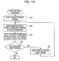
- FIG. 12 is a flow chart illustrating processing to calculate a communication cost.
- the processing in the flow chart is executed, for example, when a reference terminal is specified.
- the reference terminal is not specifically limited to but, for example, a terminal newly coupled to a network to be explored.
- terminals N 1 to N 5 form a P2P network
- the terminal 6 is a reference terminal.
- the network exploration apparatus 10 calculates communication costs from the terminal N 6 to other terminals N 1 to N 5 respectively in response to an inquiry from the terminal N 6 .
- the calculator 14 selects a calculation target terminal among a plurality of terminals coupled to the network.
- the calculation target terminal is, for example, a terminal registered in the terminal list 16 and is selected from terminals other than the reference terminal.
- the calculator 14 deletes a section list that does include neither the reference terminal nor the calculation target terminal from the topology information. Accordingly, focused topology information is obtained.
- the focused topology information is a substantially minimum network topology that includes a reference terminal and a calculation target terminal.
- the calculator 14 calculates the number of parentheses that separates a reference terminal and a calculation target terminal in the focused topology information obtained at operation S 22 .
- the number of parentheses is output as a communication cost between the reference terminal and the calculation target terminal.
- the calculator 14 searches a terminal that is not selected as a calculation target terminal. If there are terminals that are not selected as a calculation target terminal, the next calculation target terminal is selected from the unselected terminals and processing returns to operation S 22 . In other words, operations S 22 and S 23 are executed for each terminal. As a result, a communication cost between the reference terminal and other respective terminals is calculated.
- the topology information includes the following four section lists: (N 1 , N 2 ), (N 1 , N 2 , N 3 ), (N 5 , N 6 ), and (N 4 , N 5 , N 6 ).
- N 6 and N 3 are separated by three parentheses.
- a communication cost from the terminal N 6 to the terminal N 3 is “3.”
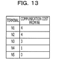
- FIG. 13 illustrates an embodiment of the communication cost table 18 when the terminal N 6 is a reference terminal.
- a cost corresponding to the switching hub SW 1 is not counted according to the embodiment. Note that in the above calculation, a cost corresponding to the switching hub SW 1 is substantially eliminated for each of the terminals, and thereby causing no problem when relative communication costs are compared. Moreover, when a terminal is added that is directly connected to the switching hub SW 1 , the presence of the switching hub SW 1 is recognized or estimated by further repeating explorations, and the cost corresponding to the switching hub SW 1 is reflected to the calculation result.
- the network exploration apparatus 10 When the communication cost table 18 in which the reference terminal is the terminal N 6 is created as described above, the network exploration apparatus 10 notifies the terminal N 6 of a partner terminal with substantially the lowest communication cost from the terminal 6 . In the example of FIG. 13 , the network exploration apparatus 10 notifies the terminal N 6 of “N 5 .” The terminal N 6 requests the terminal N 5 to set the terminal N 6 as a transfer destination of P2P communication data. The terminal N 5 that receives the request transfers P2P communication data received from other terminal (here, one of the terminals N 1 to N 4 ) to the terminal N 6 . As a result, the P2P data distribution is achieved by a route with a lower communication cost and thereby improving communication efficiency among terminals.
- the network exploration apparatus 10 may select a terminal with a lower probability of causing a loss of an exploration packet as a communication partner of P2P communication when communication costs of two or more terminals are substantially the same. Moreover, the network exploration apparatus 10 may calculate a communication cost by assuming a terminal other than a newly added terminal as a reference terminal. In other words, the network exploration apparatus 10 may calculate a communication cost by assuming any terminal as a reference.
- the network exploration apparatus 10 executes, for example, periodic explorations repeatedly and updates the group information list 17 .
- the number of times causing a packet loss increases as time elapses and thereby improving reliability of exploration results.
- the network exploration method according to the embodiment utilizes that a loss of an exploration packet is caused at a switching hub, etc.
- the network exploration method according to the embodiment may be executed when regular P2P data communication is conducted between terminals.
- a probability of causing a loss of an exploration packet due to congestion by regular P2P data communication becomes high.
- the number of samples to create the group information list 17 increases, thereby increasing reliability of the exploration.
- time desired to create the group information list 17 is reduced.
- the network exploration apparatus 10 may transmit a dummy packet in addition to an exploration packet when executing an exploration in order to increase a probability of causing a loss of the exploration packet.
- the exploration packet and the dummy packet are transmitted, for example, by time division multiplexing.
- a network exploration apparatus 10 is provided in an embodiment illustrated in FIG. 3 in order to calculate a communication cost.
- any terminal in a plurality of terminals coupled to a network to be explored calculates a communication cost between terminals as a network exploration apparatus.
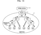
- FIG. 14 illustrates a configuration example of a network in which a network exploration method according to the other embodiment is used.
- a terminal N 1 among terminals N 1 to N 6 has a function to calculate a communication cost.
- the terminal N 1 includes a transmitter 11 , a receiver 12 , a detector 13 , a calculator 14 , a temporary list 15 , a terminal list 16 , a group information list 17 , and a communication cost table 18 .
- Two or more terminals among the terminals N 1 to N 6 may have a communication cost calculation function or each terminal may have a communication cost calculation function.
- FIG. 14 illustrates procedures in which the terminal N 1 creates the group information list 17 and calculates a communication cost between terminals are basically the same as the procedure in FIG. 3 executed by the network exploration apparatus 10 .
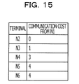
- FIG. 15 illustrates an example of a communication cost table 18 created by the terminal N 1 .
- the terminal N 1 may periodically execute the above described exploration and update the group information list 17 and the communication cost table 18 . According to the configuration, the terminal N 1 may perform P2P data distribution by almost always using a partner terminal with a lower communication cost. For example, it is assumed that the terminal N 3 is specified as a partner terminal of P2P communication of the terminal N 1 .
- the communication cost table 18 illustrated in FIG. 15 is assumed to be obtained.
- a communication cost from the terminal N 1 to the terminal N 2 is lower than that of from the terminal N 1 to the terminal N 3 .
- the terminal N 1 refers to the communication cost table 18 and switches a partner terminal of P2P communication from the terminal N 3 to the terminal N 2 . Accordingly, efficiency to transfer P2P communication data are improved.
- the above-described state may be caused, for example, when the terminal N 2 is newly coupled to the switching hub SW 3 .
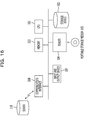
- FIG. 16 illustrates a hardware configuration of the network exploration apparatus 10 .
- the terminal device to execute the network exploration method according to an embodiment basically also includes a configuration illustrated in FIG. 16 .
- a CPU 101 provides a network exploration method according to an embodiment by executing a network exploration program using a memory 103 .
- a storage device 102 stores the network exploration program.
- the storage device 102 may be an external storage device.
- the memory 103 is, for example, a semiconductor memory and includes a Random Access Memory (RAM) area and a Read-only Memory (ROM) area.
- RAM Random Access Memory
- ROM Read-only Memory
- the network exploration apparatus is achieved by a computer that includes a CPU and a memory.
- a reader 104 accesses a portable storage medium 105 according to an instruction from the CPU 101 .
- the portable storage medium 105 includes, for example, a semiconductor device, a medium to and from which information is input and output by magnetic action, or by optical action.
- a communication interface 106 transmits and receives data through a network according to an instruction from the CPU 101 .
- An input and output device 107 corresponds to, for example, a device etc. that accepts an instruction from a user.
- the network exploration program describes the procedure of the above-described flow chart, and for example, provided by the following forms: (1) installed in the storage device 102 , (2) provided by the portable storage medium 105 , and (3) download from a program server 110 .
- the network exploration apparatus is achieved by executing the network exploration program by the computer system configured as described above.
- executing the network exploration program by the computer system configured as described above may achieve some of or all of the transmitter 11 , the receiver 12 , the detector 13 , and the calculator 14 .
- the temporary list 15 , the terminal list 16 , the group information list 17 , and the communication cost table 18 are created, for example, in the memory 103 .
Abstract
Description
- This application is based upon and claims the benefit of priority of the prior Japanese Patent Application No. 2010-199309, filed on Sep. 6, 2010, the entire contents of which are incorporated herein by reference.
- The embodiments discussed herein are related to a network exploration method and a network exploration apparatus to explore a network to which a plurality of terminals is connected.
- A load to a distribution server in a client-server data distribution system increases as the number of data reception terminals increases. Thus, in a large-scale distribution system, a capacity of a distribution server where accesses are concentrated on or a capacity of the network infrastructure needs to be increased. As a result, the distribution cost increases. Under the background, recently, a data distribution method that applies a peer-to-peer (P2P) technique has drawn attention.
- In a streaming distribution method that utilizes P2P, for example, a terminal that receives data transfers the data to another terminal. In this case, respective terminals function as relay devices and thereby achieve large-scale broadcast. According to the method, even if the number of terminals increases, a load on a distribution server will not increase much.
- The P2P data distribution may be regarded as data distribution over a logical network (or an overlay network) configured by logical links among terminals without a need to be conscious of the physical network environment. Moreover, in the P2P data distribution, an amount of data traffic that flows over the physical network is determined by a method of coupling terminals over the logical network.
-
FIG. 1 illustrates P2P data distribution. In the network ofFIG. 1 , three terminals, n1 to n3 are coupled through routers, A to D. In the network, data are assumed to be distributed from the terminal n1 to the terminal n2 and the terminal n3 by the P2P method. In this case, data distribution from the terminal n1 to the terminal n2 and the terminal n3 is achieved, for example, by the following procedure A or procedure B. In procedure A, the terminal n1 transmits data to the terminal n2, and the terminal n2 transfers the data to the terminal n3. In procedure B, the terminal n1 transmits data to the terminal n3 and the terminal n3 transfers the data to the terminal n2. - An appropriate selection of a procedure with a shorter network distance of data distribution increases efficiency of data distribution. The network distance is represented, for example, by the number of routers over the communication route. For example, in a
procedure 1, three routers, C, B, and A are present over a route from the terminal n1 to the terminal n2 while two routers A and D are present over a route from the terminal n2 to the terminal n3. In other words, the total network distance of theprocedure 1 is “5.” Meanwhile, in aprocedure 2, four routers, C, B, A, and D are present over a route from the terminal n1 to the terminal n3 while two routers D and A are present over a route from the terminal n3 to the terminal n2. In other words, the total network distance of theprocedure 2 is “6.” In this case, selectingprocedure 1 instead ofprocedure 2 increases efficiency of the data distribution. Note that the number of routers over a communication route may be detected, for example, by a traceroute command or a tracert command. -
FIG. 2 illustrates an example of a subnetwork that includes a plurality of switching hubs. In the example ofFIG. 2 , the subnetwork includes five switching hubs, SW1 to SW5 and configured under a control of a router. The terminals N1 to N6 may transmit and receive data through the switching hubs SW1 to SW5. - In the example below, operations will be described under an assumption that a network topology (a network distance) may be identified in the same manner as the network configured by routers in
FIG. 1 may be identified. - In the example, data are assumed to be transmitted from the terminal N1 to terminals, N2 to N6 by the P2P method. In this case, the terminal N1 transmits data to a destination terminal with substantially the shortest network distance. In the configuration illustrated in
FIG. 2 , the terminal N1 transmits data to the terminal N2. The terminal N2 transfers the received data to another destination terminal with substantially the shortest network distance. In the configuration illustrated inFIG. 2 , terminal N2 transfers the data to the terminal N3. Thereafter, each terminal transfers the received data to another terminal based on the network distance. Accordingly, efficient data distribution from the terminal N1 to terminals, N2 to N6 may be achieved. - As a related technology, Japanese Laid-open Patent Publication No. 2000-172600 discusses a network configuration exploration method that is capable of identifying devices to be managed that are connected to a network using different protocols. In the network configuration exploration method, types of protocols that can be used are obtained and exploration requests are transmitted that request devices coupled using all types of protocols to respond. Then responses from the devices are calculated and a device list used for managing the devices is displayed based on the calculated result.
- As another related technology, Japanese Laid-open Patent Publication No. 2006-345347 discusses a communication apparatus that performs configuration exploration of a customer premises network. The communication apparatus includes an exploration packet generation unit, a received packet analysis unit, a control unit, and a packet transmission and reception unit. The exploration packet generation unit generates a router exploration packet in which time to live (TTL) is changed and switches a transmission destination of the router exploration packet. The received packet analysis unit obtains an address of the router from an Internet Control Message Protocol (ICMP) packet that is returned from the router in response to the router exploration packet. The control unit obtains information from the received packet analysis unit, controls the router exploration packet generation unit, and conducts the network exploration. The packet transmission and reception unit transmits and receives the router exploration packet and the ICMP packet.
- A network exploration apparatus is configured to calculate a communication cost of a network to which a plurality of terminals is coupled through a plurality of network devices, the network exploration apparatus including: a transmitter configured to transmit an exploration packet to the plurality of terminals; a receiver configured to receive a response packet for the exploration packet; a detector configured to detect a terminal group to which a terminal that does not receive the exploration packet among the plurality of terminals belongs based on a reception result of the response packet by the receiver; and a calculator configured to calculate a communication cost between terminals based on an inclusion relationship between a plurality of terminal groups detected by the detector when the transmitter repeatedly transmits the exploration packet.
- The object and advantages of the invention will be realized and attained by means of the elements and combinations particularly pointed out in the claims.
- It is to be understood that both the foregoing general description and the following detailed description are exemplary and explanatory and are not restrictive of the invention, as claimed.
- These and/or other aspects and advantages will become apparent and more readily appreciated from the following description of the embodiments, taken in conjunction with the accompanying drawings of which:
-
FIG. 1 illustrates P2P data distribution; -
FIG. 2 illustrates an example of a subnetwork that includes a plurality of switching hubs; -
FIG. 3 illustrates a configuration example of a network in which a network exploration method according to an embodiment is used; -
FIG. 4 illustrates a configuration of a network exploration apparatus; -
FIG. 5A is an embodiment of an exploration packet; -
FIG. 5B is an embodiment of a response packet; -
FIG. 6A is an embodiment of a temporary list; -
FIG. 6B is an embodiment of a terminal list; -
FIG. 7A illustrates a method to detect a terminal group; -
FIG. 7B illustrates a method to detect a terminal group; -
FIG. 8 is an embodiment of a group information list; -
FIG. 9 is a flow chart illustrating processing to create a group information list; -
FIG. 10 is a flow chart illustrating processing to aggregate terminal groups; -
FIG. 11A illustrates a case when an inclusion relationship among terminal groups contradicts; -
FIG. 11B illustrates a case when an inclusion relationship among terminal groups contradicts; -
FIG. 11C illustrates a case when an inclusion relationship among terminal groups contradicts; -
FIG. 12 is a flow chart illustrating processing to calculate a communication cost; -
FIG. 13 is an embodiment of a communication cost table; -
FIG. 14 is an example of a network configuration in which a network exploration method according to another embodiment is used; -
FIG. 15 is an embodiment of a communication cost table created by another embodiment; and -
FIG. 16 illustrates a hardware configuration of a network exploration apparatus. - Reference may now be made in detail to embodiments of the present invention, examples of which are illustrated in the accompanying drawings, wherein like reference numerals refer to like elements throughout.
- As described above, when data are distributed to a plurality of terminals by the P2P method, each terminal transfers data to a destination terminal with a shorter network distance, and thereby efficient data distribution may be achieved. However, data may not be distributed efficiently when a network is configured by a Layer 2 (L2) switch (or a switching hub) due to the following reasons. Note that “L2” indicates the
layer 2 of the Open Systems Interconnection (OSI) reference model. - The L2 switch transfers the data based on destination information of the data, however the L2 switch may not process a command (for example, a trace route command) of an IP layer or a higher layer. Hence, in a network configured with an L2 switch, communication terminals (for example, terminals, L2 switches, and a network management device) may not detect an L2 switch from the IP layer or a higher layer, and thereby the number of L2 switches over a communication route may not be measured. In other words, measuring a network distance between terminals is difficult. As a result, each terminal may not appropriately select a destination terminal with a shorter network distance in the network and data are inefficiently distributed.
- The present disclosure achieves a mechanism capable of estimating a communication cost in order to improve communication efficiency among terminals in a network to which a plurality of terminals is coupled.
- Hereinafter, embodiments will be described by referring to accompanying drawings.
-
FIG. 3 illustrates a configuration example of a network in which a network exploration method according to an embodiment is used. In the example, a network exploration method according to the embodiment is used in asubnetwork 2 that is coupled to arouter 1. Therouter 1 couples anexternal network 3 with thesubnetwork 2. Furthermore, therouter 1 in the example provides functions of thelayer 3 or higher of the OSI reference model, and for example, provides a function to respond to a trace route command, etc. - The
subnetwork 2 is configured with a plurality of network devices (according to the embodiment, switching hubs SW1 to SW5). The switching hub SW1 is coupled to therouter 1. The switching hub SW2 and the switching hub SW4 are coupled to the switching hub SW1. Moreover, the switching hub SW3 is coupled to the switching hub SW2 and the switching hub SW5 is coupled to the switching hub SW4. The switching hubs SW1 to SW5 are, for example, L2 switches. In other words, it is assumed that the switching hubs SW1 to SW5 in this example may not execute an IP command and a protocol command of thelayer 3 or higher. - Six terminals N1 to N6 are coupled to the
subnetwork 2. The terminal N1 and the terminal N2 are accommodated in the switching hub SW3. The terminal N3 is accommodated in the switching hub SW2. The terminal N4 is accommodated in the switching hub SW4. The terminal N5 and the terminal N6 are accommodated in the switching hub SW5. - Each of the terminals N1 to N6 has a function to transmit and receive data to and from another terminal by peer-to-peer (P2P). Destination information to achieve broadcast by P2P is set in each of the terminals N1 to N6. For example, destination information of N1, N2, N3, N4, N5, and N6 other than that of own terminal is set in the terminals N1, N2, N3, N4, N5, and N6 respectively. In this case, the
router 1 transfers broadcast data addressed to the terminal N1 that is received from theexternal network 3 to the terminal N1 by way of the SW1, SW2, and SW3. - The terminal N1 refers to destination information and transfers the broadcast data received from the
external network 3 to the terminal N2 via the SW3. The terminal N2 refers to the destination information and transfers the broadcast data received from the terminal N1 to the terminal N3 by way of SW3 and SW2. Likewise, the terminals N3, N4, and N5 transfer the broadcast data to the terminals N4, N5, and N6 respectively via SWs according to the destination information. Accordingly, the terminals N1 to N6 receive the broadcast data. The terminal N6 may further transfer the received broadcast data to other terminal in another subnetwork. - A
network exploration apparatus 10 is a server computer, detects a topology of thesubnetwork 2, and calculates communication costs among the terminals N1 to N6. Although details of the communication cost will be described later, for example, the communication cost corresponds to the number of switching hubs that are present over a communication route among terminals. Furthermore, anetwork exploration apparatus 10 may generate the above-described destination information based on communication costs among the terminals N1 to N6. In this case, the destination information is determined so as to substantially optimize communication efficiency of the above-described broadcast distribution. Thenetwork exploration apparatus 10 may distribute destination information to the terminals N1 to N6. Alternatively, the terminals N1 to N6 may request corresponding destination information to thenetwork exploration apparatus 10. - In the example of
FIG. 3 , thenetwork exploration apparatus 10 is coupled to the switching hub SW1. However, thenetwork exploration apparatus 10 may be coupled to any of the switching hubs SW2 to SW5. Moreover, thenetwork exploration apparatus 10 may be coupled to therouter 1 or may be provided over theexternal network 3. -
FIG. 4 illustrates a configuration of thenetwork exploration apparatus 10. Thenetwork exploration apparatus 10 according to the embodiment includes atransmitter 11, areceiver 12, adetector 13, and acalculator 14. - The
transmitter 11 transmits exploration packets to all terminals coupled to a network to be explored. In the example ofFIG. 3 , thetransmitter 11 transmits exploration packets to each of the terminals N1 to N6 that are coupled to thesubnetwork 2. - The
transmitter 11 transmits exploration packets by IP multicast or broadcast, although the embodiment is not limited to this. For example, when IP multicast is executed, an IP multicast address (for example, “224.0.0.1”) is set in the IP header and the terminals N1 to N6 are set so as to receive exploration packets of the IP multicast address. In this case, the switching hubs SW1 to SW5 inFIG. 3 transfer exploration packets transmitted from thenetwork exploration apparatus 10 to the terminals N1 to N6 according to the multicast address. - At this time, exploration packets transmitted from the
network exploration apparatus 10 are transferred to therouter 1 as well. Therouter 1 is set so as not to transmit the received exploration packets to anexternal network 2, although the embodiment is not limited to this. Alternatively, there is no terminal to receive the above-described multicast address at theexternal network 2 and the received exploration packets are not transmitted to theexternal network 2. - The
transmitter 11 transmits an exploration packet by a protocol without a retransmission function, although the embodiment is not limited to this. In other words, thetransmitter 11 transmits an exploration packet, for example, by User Datagram Protocol (UDP). - As illustrated in
FIG. 5A , an ID, an exploration number, a return address, and a return port are set in an exploration packet. The ID indicates a packet type. Thus, a certain value indicating an exploration packet is set in an ID field of an exploration packet. The exploration number corresponds to a sequence number to identify each transmission procedure when thenetwork exploration apparatus 10 repeats procedure to transmit exploration packets to the terminals N1 to N6. Accordingly, the same exploration number is assigned to each exploration packet transmitted to the terminals N1 to N6 by multicast or broadcast at one time. - The return address and the return port represent an address indicating destination to which the terminal that receives the exploration packet returns a response packet and the TCP/IP port number respectively. According to the embodiment, an IP address of the
network exploration apparatus 10 is set in the return address. A reserved port number to receive a response packet at thenetwork exploration apparatus 10 is set in the return port. - When each of the terminals N1 to N6 receives the above-described exploration packet, creates a response packet illustrated in
FIG. 5B and returns the response packet to thenetwork exploration apparatus 10. At this time, each of the terminals N1 to N6 transmits a response packet by a protocol with a retransmission function, although the embodiment is not limited to this. In other words, each of the terminals N1 to N6 transmits a response packet, for example, by Transmission Control Protocol (TCP). - The “return address” notified by an exploration packet is set in the destination IP address of the IP header of the response packet. In other words, the destination IP address of the response packet is an IP address of the
network exploration apparatus 10. The “return port” that is notified by an exploration packet is set in the destination port number of the TCP header of the response packet. Moreover, a certain value that indicates the response packet is set in the ID field of the response packet. An exploration number of the received exploration packet is used as it is for the exploration number set in the response packet. - When each of the terminals N1 to N6 receives the exploration packet, transmits the above-described response packet to the
network exploration apparatus 10. The switching hubs SW1 to SW5 transfer the response packets transmitted from the terminals N1 to N6 to thenetwork exploration apparatus 10. At this time, the response packet includes information to identify a transmission source terminal of the response packet. The information to identify a transmission source terminal is, for example, a transmission source IP address set in an IP header. Accordingly, thenetwork exploration apparatus 10 may detect the transmission source terminal of the response packet. - The
receiver 12 receives a response packet for the exploration packet transmitted from thetransmitter 11. According to the embodiment, thereceiver 12 waits for response packets to be transmitted from the terminals N1 to N6 at a TCP port indicated by the above-described “return port.” Thereceiver 12 passes the response packets received from the terminals N1 to N6 to thedetector 13. Note that thereceiver 12 waits for response packets for the exploration packet typically for a time period until a certain time AT elapses from when thetransmitter 11 transmits the exploration packets. - For example, when the
transmitter 11 transmits an exploration packet in which an exploration number 001 is set at time T1, thereceiver 12 waits for a response packet to which the exploration number 001 is set until time T1+ΔT. Subsequently, when thetransmitter 11 transmits an exploration packet to which an exploration number 002 is set at time T2, thereceiver 12 waits for the response packet in which the exploration number 002 is set until time T2+ΔT. - The exploration number set in the exploration packet and transmission time of the exploration packet are notified, for example, from the
transmitter 11 to thereceiver 12. Alternatively, thedetector 13 may manage exploration numbers. In this case, the exploration number is notified from thedetector 13 to thetransmitter 11 and thereceiver 12. - The
detector 13 detects a terminal group to which a terminal that does not receive the exploration packet belongs among all of the terminals coupled to the network to be explored based on the reception result of the exploration packet by thereceiver 12. In other words, thedetector 13 detects a terminal group to which a terminal that does not receive the exploration packet belongs among the terminals N1 to N6. Thedetector 13 detects the terminal group by using thetemporary list 15 and theterminal list 16. Thetemporary list 15 and theterminal list 16 may be provided in thedetector 13 or outside of thedetector 13. Thedetector 13 detects a terminal group for each exploration number (in other words, whenever exploration packets are transmitted to the terminals N1 to N6 by multicast or broadcast). -
FIG. 6A is an embodiment of thetemporary list 15. A transmission source terminal of a response packet is registered in thetemporary list 15 for each exploration number. In other words, thedetector 13 checks an exploration number and a transmission source terminal of a response packet received by thereceiver 12. The transmission source terminal of the response packet is identified, for example, by a transmission source IP address set in the IP header. - The
detector 13 registers a transmission source terminal of a received response packet in thetemporary list 15 whenever thereceiver 12 receives a response packet. The example ofFIG. 6A illustrates a state of thetemporary list 15 when thetransmitter 11 transmits exploration packets with anexploration number 100 to the terminals N1 to N6 and thereceiver 12 receives response packets for the exploration packets from the terminals N3, N4, N5, and N6. -
FIG. 6B is an embodiment of theterminal list 16. Terminals coupled to a network to be explored are registered in theterminal list 16. According to the embodiment, the terminals N1, N2, N3, N4, N5, and N6 that are coupled to thesubnetwork 2 are registered in theterminal list 16. When terminals that are coupled to a network to be explored are known, theterminal list 16 is prepared beforehand. On the other hand, terminals to be coupled to a network to be explored are unknown, theterminal list 16 is created, for example, by the following procedure A: - (a1) transmit an exploration packet by multicast or broadcast.
- (a2) register a transmission source terminal of a response packet for the exploration packet transmitted at (a1).
- (a3) compare the
temporary list 15 with theterminal list 16, and if there is a terminal listed only in the temporary list, add the terminal to theterminal list 16. - (a4) reset the
temporary list 15. - (a5) repeat the above described (a1) to (a4) for the certain number of times.
- The
detector 13 may detect a terminal group while creating theterminal list 16 at the above procedure (a1) to (a5). Alternatively, thedetector 13 may detect a terminal group after creating theterminal list 16 at the procedure (a1) to (a5). - The
detector 13 detects a terminal group by the following procedure B: - (b1) instruct the
transmitter 11 to transmit an exploration packet. Accordingly, thetransmitter 11 transmits exploration packets to the terminals N1 to N6 by multicast or broadcast. At this time, the exploration packets are transmitted basically to all terminals registered in theterminal list 16. - (b2) register transmission source terminals of response packets (in other words, a response packet with an exploration number “i”) corresponding to the exploration packets transmitted at (b1) in the
temporary list 15. - (b3) refer to the
temporary list 15 and theterminal list 16 and detect a terminal that is registered in theterminal list 16 but not registered in thetemporary list 15. The detected one or more terminals are “a terminal other than the transmission source terminal of the response packet” - (b4) output a terminal group elements of which are the one or more terminals detected at (b3) as a terminal group obtained for an exploration number “i.”
- (b5) reset the
temporary list 15. - As described above, the
detector 13 detects the terminal group elements of which are “a terminal other than the transmission source terminal of the response packet” for the exploration number “i.” In the example ofFIG. 6 , the terminals N1 to N6 are registered in theterminal list 16, and the terminals N3 to N6 are registered in thetemporary list 15 for theexploration number 100. In other words, the terminals N1 and N2 are registered in theterminal list 16 but not registered in thetemporary list 15. In this case, thedetector 13 outputs “terminal group=N1, N2” for theexploration number 100. - The
detector 13 repeats the above-described procedure (b1) to (b5) while counting up the exploration number “i.” Note that when all terminals registered in thetemporary list 15 match all terminals registered in theterminal list 16, no terminal group is detected. In other words, “terminal group=not available” is output. -
FIG. 7 illustrates a method to detect a terminal group. Here, it is assumed that thenetwork exploration apparatus 10 transmits exploration packets to the terminals N1 to N6 by multicast or broadcast. At this time, the exploration packets basically reach all of the terminals N1 to N6. Note that, packets transmitted through a network may be discarded, for example, when the network is congested. In other words, packet loss of exploration packets transmitted from thenetwork exploration apparatus 10 to the terminals N1 to N6 may be caused over the network. - In the example of
FIG. 7( a), congestion is caused at the switching hub SW3, and the exploration packet is discarded at the switching hub SW3. In this case, exploration packets transmitted from thenetwork exploration apparatus 10 reach the terminals N3 to N6, however do not reach the terminals N1 to N2. The exploration packets according to the embodiment are transmitted by a protocol without a retransmission function. Accordingly, when a packet loss is caused at the switching hub SW3, the terminals N1 to N2 do not receive the above described exploration packets. - When the terminals N3 to N6 receive the exploration packets, the terminals N3 to N6 create corresponding response packets and return the response packets to the
network exploration apparatus 10 respectively. At this time, the response packets are transmitted by a protocol with a retransmission function. Hence, the response packets transmitted from the terminals N3 to N6 surely reach thenetwork exploration apparatus 10 even if thesubnetwork 2 is congested. In other words, thenetwork exploration apparatus 10 receives the response packets from the terminals N3 to N6. - Meanwhile, the terminals N1 and N2 in the example do not receive exploration packets; thereby neither of the terminals N1 to N2 transmits a response packet. Accordingly, the
network exploration apparatus 10 does not receive any response packet from the terminals N1 and N2. - The
detector 13 of thenetwork exploration apparatus 10 groups the terminals N1 and N2 if thedetector 13 may not receive response packets from the terminals N1 and N2 within a certain time period. In other words, a terminal group, “N1, N2” is detected. - As described above, a terminal that receives an exploration packet returns a response packet to the
network exploration apparatus 10. The response packet transmitted by the terminal surely reaches thenetwork exploration apparatus 10 as described above. Accordingly, a cause that thenetwork exploration apparatus 10 may not receive the response packets from the terminals N1 and N2 is considered that the exploration packets do not reach the terminals N1 and N2. - In other words, terminals other than a transmission source terminal of the response packet do not receive the exploration packets and the terminal N1 and N2 are grouped as “terminals that may not receive exploration packets.” Moreover, a cause that exploration packets do not reach the terminal N1 and N2 is that the exploration packets may be discarded at a network device (according to the embodiment, a switching hub SW3) related to both the terminals N1 and N2.
- Hence, the terminal group detected as described above may be used as information that indicates a network topology. For example, when the terminal group, “N1, N2” is detected, the terminals N1 and N2 are coupled to the same switching hub, or the terminals N1 and N2 are coupled to the same switching hub viewed from the
network exploration apparatus 10. In the example ofFIG. 7A , both the terminals N1 and N2 are coupled to the switching hub SW3. - In the example of
FIG. 7B , congestion is caused at the switching hub SW4 and exploration packets are discarded at the switching hub SW4. In this case, exploration packets transmitted from thenetwork exploration apparatus 10 reach the terminals N1 to N3; however do not reach the terminals N4 to N6. - In this case, the
network exploration apparatus 10 receives response packets from the terminals N1 to N3, however do not receive response packets from the terminals N4 to N6. Thedetector 13 groups the terminals N4, N5, and N6. In other words, a terminal group “N4, N5, and N6” is detected. - When the terminal group “N4, N5, and N6” is detected, the exploration packets are considered to be discarded with a high possibility at a network device (according to the embodiment, the switching hub SW4) that is commonly related to in the terminals N4, N5, and N6. In this case, the terminals N4, N5, and N6 are coupled to the same switching hub, or the terminals N4, N5, and N6 are coupled to the same switching hub viewed from the
network exploration apparatus 10. In the example ofFIG. 7B , all of the terminals N4, N5, and N6 are coupled to the switching hub SW4 viewed from thenetwork exploration apparatus 10. - The
network exploration apparatus 10 repeatedly executes the above-described exploration. The “exploration” corresponds to a procedure that transmits exploration packets to all terminals coupled to thesubnetwork 2 and monitors the responses. Thedetector 13 detects a plurality of terminal groups according to whether a response packet for each exploration may be received from each terminal. The terminal groups detected by thedetector 13 are notified to thecalculator 14. - The
calculator 14 calculates a communication cost between terminals based on an inclusion relationship among the plurality of terminal groups detected by thedetector 13. Thecalculator 14 calculates the communication cost between terminals while updating and referring to agroup information list 17. -
FIG. 8 is an embodiment of thegroup information list 17. A terminal group detected by thedetector 13 is registered in thegroup information list 17. In the example ofFIG. 8 , the following six terminal groups are registered in thegroup information list 17. The six groups are “N1, N2”, “N4, N5, N6”, “N1, N2, N3”, “N5, N6”, “N1, N2, N3, N4, N5, N6”, and “N1, N2, N5, N6.” For example, the terminal group, “N1, N2” is registered when thenetwork exploration apparatus 10 may not receive response packets from the terminals N1 and N2. For example, the terminal group, “N4, N5, N6” is registered when thenetwork exploration apparatus 10 may not receive response packets from the terminals N4, N5, and N6. - Moreover, the
group information list 17 manages a detection frequency of each terminal group (a frequency counter inFIG. 8 ). The detection frequency in the example indicates the number of times a terminal group is detected by thedetector 13. In other words, thecalculator 14 counts up a frequency counter of a terminal group when thedetector 13 detects the terminal group. In the example ofFIG. 8 , for example, the terminal group, “N1, N2” is detected at 15 times and the terminal group, “N4, N6” is detected at 12 times. Furthermore, thecalculator 14 sorts terminal groups registered in thegroup information list 17 according to the detection frequencies. -
FIG. 9 is a flow chart illustrating processing to create thegroup information list 17. The processing is executed by thetransmitter 11, thereceiver 12, thedetector 13, and thecalculator 14. The execution of processing is, for example, repeated periodically. - The
detector 13 sets an exploration number at operation S1. The exploration number is, for example, a sequence number and different values are used for respective explorations. As described above, the “exploration” corresponds to a procedure to transmit exploration packets to all terminals coupled to thesubnetwork 2 and detects the responses. Thedetector 13 notifies an exploration number to thetransmitter 11 and thereceiver 12. In the example, thedetector 13 generates exploration numbers; however other circuit components may generate exploration numbers. - At operation S2, the
transmitter 11 creates exploration packets and transmits the exploration packets to all terminals coupled to thesubnetwork 2. At this time, the exploration number notified by thedetector 13 is set in the exploration packet. Moreover, the exploration packets are transmitted by multicast or broadcast. - At operation S3, the
receiver 12 and thedetector 13 collect exploration results. In other words, thereceiver 12 waits for a response packet in which an exploration number notified by thedetector 13 is set until a certain time period elapses from when thetransmitter 11 transmits the exploration packets. Thedetector 13 compares a transmission source terminal of each response packet received by thereceiver 12 with terminals registered in theterminal list 16. It is considered that the transmission source terminal of the response packet receives the exploration packet while other terminals do not receive exploration packets. In other words, a terminal that does not receive an exploration packet is detected. - At operation S4, the
detector 13 determines whether there is any terminal that does not receive an exploration packet based on a reception state of the response packets. If there is any terminal that does not receive an exploration packet, the processing proceeds to operation S5. When thereceiver 12 receives response packets from all of the terminals, the processing is completed. - At operation S5, the
detector 13 groups terminals that do not receive exploration packets. Thecalculator 14 increments a frequency counter (counts up a count value for 1) of the terminal group detected by thedetector 13 in thegroup information list 17. Thecalculator 14 sorts the updatedgroup information list 17 according to the value of the frequency counter. - Accordingly, the
network exploration apparatus 10 creates thegroup information list 17 by repeatedly executing processing of the flow chart inFIG. 9 . The processing of operations S5 to S6 are executed basically when an exploration packet transmitted by thenetwork exploration apparatus 10 is discarded at any of the switching hubs in thesubnetwork 2. In other words, thegroup information list 17 is updated basically when an exploration packet is discarded. - The
calculator 14 executes aggregation of terminal groups by using thegroup information list 17 created as described above. The aggregation of the terminal groups corresponds to processing to detect a topology of a network to be explored. -
FIG. 10 is a flow chart illustrating processing to aggregate terminal groups. The processing of the flow chart is executed, for example, by thecalculator 14 after thegroup information list 17 is created. - At operation S11, the
calculator 14 initializes topology information. The topology information is created in a certain memory area (not illustrated) in thenetwork exploration apparatus 10. - At operation S12, the
calculator 14 selects a terminal group with substantially the largest frequency counter value in thegroup information list 17. It is assumed that terminal groups are sorted according to values of the frequency counters in thegroup information list 17. - At operation S13, the
calculator 14 determines whether there is any common element between processing target group information and the topology information. The processing target group information indicates one or a plurality of terminal groups that belongs to the terminal group selected at operations S12 or S19. The topology information indicates a relationship between terminals and will be described later by referring to an embodiment. The topology information does not include any element at operation S11 when the topology information is initialized. Moreover, the topology information is updated at Operation S14 or Operation S16. If there is any common element (in other words, a terminal ID) between the processing target group information and the topology information, the processing proceeds to operation S14, and otherwise the processing proceeds to operation S17. - At operation S14, the
calculator 14 detects whether there is any inclusion relationship between processing target group information and each section list in the topology information. Here, each section list will be described later by referring to an embodiment, and includes one or more terminal IDs. For example, processing target group information is “N1, N2” and a section list in the topology information is “(N1, N2, and N3)”. In this case, the section list is determined to include the processing target group information. Moreover, processing target group information is “N1, N2” and a section list in the topology information is “(N2, and N3)”. In this case, “N1” that belongs to the processing target group information is not an element of the section list and “N3” that belongs to the section list is not an element of the processing target group information. Thus, it is determined that there is no inclusion relationship between the processing target group information and the topology information. - If there is any inclusion relationship between the processing target group information and the section list in the topology information (operation S14: Yes), the
calculator 14 updates the topology information at operation S15. At this time, the section list having the inclusion relationship with the processing target group information is replaced with an inclusion list that indicates the inclusion relationship between the processing target group information and the topology information. - If there is no inclusion relationship between the processing target group information and the section list in the topology information (operation S14: No), the
calculator 14 determines that the processing target group information includes an error atstep 16. In this case, the processing of operation S15 is skipped. Moreover, the processing target group information is discarded. - If there is no common element between the processing target group information and the topology information (operation S13: No), the
calculator 14 adds a terminal list represented by the processing target group information to the topology information as a new section list at operation S17. In this case, the processing of operation S15 is also skipped. - At operations S18 and S19, the
calculator 14 checks whether all of the terminal groups registered in thegroup information list 17 are selected. If there is any unselected terminal group in thegroup information list 17, thecalculator 14 selects the next terminal group and returns to operation S13. In other words, thecalculator 14 sequentially selects terminal groups one by one from thegroup information list 17 according to the frequency counters and executes processing of operations S13 to S19 respectively. Accordingly, the terminal groups are aggregated and the topology information is generated. - Now, processing to aggregate terminal groups in
FIG. 10 is described. Here, thegroup information list 17 inFIG. 8 is assumed to be already created. - A terminal group with substantially the largest frequency counter value is selected from the
group information list 17 inFIG. 8 . In other words, the terminal group, “N1, N2” is selected. At this time, no common element is present between the processing target group information and the topology information because the topology information is initialized, and thereby operation S13 is determined to be “No.” Therefore, at operation S17, the terminal group, “N1, N2” is added to the topology information as one section list. As a result, the topology information is updated as follows:topology information 1=(N1, N2). - Note that topology information “i” (i=1,2,3, . . . ) represents topology information when aggregation processing for “i” th terminal group is executed. The parenthesis in the notation of the topology information indicates a terminal group. In other words, the plurality of terminals in one parenthesis indicates that the terminals belong to the same terminal group.
- The terminal group with the second highest frequency is selected. In other words, the terminal group, “N4, N5, N6” is selected. No common element is present between the selected terminal group “N4, N5, N6” and the
topology information 1 “(N1, N2).” In this case, it is determined that the terminals that belong to the processing target group information and the terminals that belong to thetopology information 1 are assumed to be arranged in parallel. At operation S17, the terminal group, “N4, N5, N6” is added to the topology information as a new section list. As a result, the topology information is updated as follows:topology information 2=(N1, N2) (N4, N5, N6). Terminals in different parentheses in the notation of the topology information belong to different groups. - The third terminal group, “N1, N2, N3” is selected. There are common elements between the selected terminal group, “N1, N2, N3” and the
topology information 2 “(N1, N2) (N4, N5, N6).” Moreover, an inclusion relationship is present between the selected terminal group, “N1, N2, N3” and a section list of thetopology information 2 “(N1, N2).” In other words, each of the elements in the section list “(N1, N2)” is included in the elements of the terminal group “N1, N2, N3.” Hence, in this case, an inclusion list “((N1, N2), N3)” that indicates the inclusion relationship is created at operation S15. Furthermore, the section list “(N1, N2)” having an inclusion relationship with the processing target group information is replaced with the inclusion list “((N1, N2), N3)” that indicates the inclusion relationship between the processing target group information and the topology information. As a result, the topology information is updated as follows: -
Topology information 3=((N1, N2) N3) (N4, N5, N6) - In notations of topology information and an inclusion list, the multiple parentheses indicate the terminal groups have a parent and child relationship. For example, “((N1, N2) N3)” indicates a child terminal group “N1, N2” is present in the terminal group, “(N1, N2) N3.”
- The fourth terminal group “N5, N6” is selected. Here, common elements are present between the selected terminal group, “N5, N6” and the
topology information 3, ((N1, N2) N3) (N4, N5, N6). Moreover, an inclusion relationship is present between the selected terminal group, “N5, N6” and a section list of thetopology information 3 “(N4, N5, N6).” In other words, each of the elements in the section list “(N5, N6)” is included in the elements of the section list “(N4, N5, N6).” Therefore, the inclusion list (N4, (N5, N6)) that indicates the inclusion relationship is created at operation S15. The section list “(N4, N5, N6)” of thetopology information 3 is replaced with the inclusion list, “(N4, (N5, N6)).” As a result, the topology information is updated as follows: -
Topology information 4=((N1, N2) N3) (N4 (N5, N6)) - When the fifth terminal group, “N1, N2, N3, N4, N5, N6” is selected, the topology information is updated in the same manner as follows:
-
Topology information 5=((N1, N2) N3) (N4 (N5, N6)) - Moreover, the sixth terminal group, “N1, N2, N5, N6” is selected. Common elements are present between the selected terminal group, “N1, N2, N5, N6” and the
topology information 5 “((N1, N2) N3) (N4 (N5, N6)).” However, no inclusion relationship is present between the selected terminal group, “N1, N2, N5, N6” and each of the section lists of thetopology information 5. Thetopology information 5 includes thesection list 1 “(((N1, N2) N3))”, and thesection list 2 “(N4 (N5, N6)).” - However, “N3” that belongs to the
section list 1 does not belong to the above-described terminal group, and N5 and N6 that belong to the above-described terminal list do not belong to thesection list 1. In other words, no inclusion relationship is present between the sixth terminal list and thesection list 1. Likewise, no inclusion relationship is present between the sixth terminal list and thesection list 2. Accordingly, operation S14 determined to be “No”. At operation S16, an error is detected. - When operations S13 to S17 are executed for all of the terminal groups registered in the
group information list 17 as described above, thecalculator 14 outputs the created topology information. In the above example, thecalculator 14 outputs thetopology information 5. - As described above, the
calculator 14 creates and outputs topology information by executing operations S13 to S17 for each terminal group registered in thegroup information list 17. However, topology information may be created by executing operations S13 to S17 for some of the terminal groups registered in thegroup information list 17. - For example, operations S13 to S17 may be executed for a terminal group the frequency counter value of which exceeds a certain threshold. In this case, the threshold may be determined, for example, by the number of terminals coupled to a network to be explored, and/or the number of times to execute explorations. In the example of
FIG. 8 , the threshold is assumed to be “6”, for example. Processing of operations S13 to S17 is executed for the top 4 terminal groups and the above-describedtopology information 4 is output. - Alternatively, the
calculator 14 may end the aggregation processing of the terminal groups if operation S14 is determined to be “No” and an error is detected. In other words, aggregation processing of the terminal groups may be ended if any contradiction is caused in the inclusion relationship between previously selected terminal groups and a newly selected terminal group. - A case is described in which an inclusion relationship between terminal groups contradicts and an error is detected at operation S16. It is assumed as an example that two terminal groups “N1, N2” and “N2, N3” are detected and registered in the
group information list 17. The terminal group “N1, N2” is detected when “the terminal N3 receives an exploration packet, however the terminals N1 and N2 do not receive exploration packets.” In other words, the terminal group “N1, N2” is detected, for example, when a loss of an exploration packet is caused at a switching hub SW-X in a network topology illustrated inFIG. 11A . - Meanwhile, the terminal group “N2, N3” is detected when “the terminal N1 receives an exploration packet, however, the terminals N2 and N3 do not receive exploration packets.” In other words, the terminal group “N2, N3” is detected, for example, when a loss of an exploration packet is caused at a switching hub SW-Y in a network topology illustrated in
FIG. 11B . - As described above, when terminal groups “N1, N2” and “N2, N3” that contradict each other are detected, different network topologies are estimated as in
FIGS. 11A and 11B . In other words, when terminal groups that contradict each other are detected, the network topology may not be estimated. Thus, the network exploration method according to the embodiment estimates a network topology based on a terminal group with a higher detection frequency when terminal groups that contradict each other are detected. - For example, processing of the flow chart in
FIG. 10 is executed for terminal groups in order of a terminal group with a greater frequency counter value. If an inclusion relationship between the previously selected terminal group and newly selected terminal group contradicts, group information of the newly selected terminal group is ignored in the flow chart inFIG. 10 . - For example, a network topology in
FIG. 11A is estimated when the detection frequency of the terminal group “N1, N2” is higher than that of the terminal group “N2, N3.” A state that the terminal group “N2, N3” is detected in the network topology illustrated inFIG. 11A is when packet losses are caused at two points as illustrated inFIG. 11C . In other words, the terminal group “N2, N3” is detected when a packet loss of an exploration packet is caused at a switching hub SW-W provided between the switching hub SW-X and the terminal N2, and a packet loss of an exploration packet is caused at a switching hub SW-Z provided between the switching hub SW-Y and the terminal N3 as well. - However, a probability of causing packet losses at two points at substantially the same time at one exploration is very low. In other words, for example, in the network topology in
FIG. 1A , a frequency to detect the terminal group “N2, N3” is very low. Hence, estimating an inappropriate network topology at aggregating processing of terminal groups may be avoided by not using a terminal group with a frequency counter value lower than a certain threshold. - The
calculator 14 calculates a communication cost between terminals coupled to a network to be explored based on the topology information created as described above. According to the embodiment, the topology information is converted into the communication cost table. -
FIG. 12 is a flow chart illustrating processing to calculate a communication cost. The processing in the flow chart is executed, for example, when a reference terminal is specified. The reference terminal is not specifically limited to but, for example, a terminal newly coupled to a network to be explored. In other words, for example, terminals N1 to N5 form a P2P network, and when a terminal N6 is newly coupled to the P2P network, theterminal 6 is a reference terminal. In this case, thenetwork exploration apparatus 10 calculates communication costs from the terminal N6 to other terminals N1 to N5 respectively in response to an inquiry from the terminal N6. - At operation S21, the
calculator 14 selects a calculation target terminal among a plurality of terminals coupled to the network. The calculation target terminal is, for example, a terminal registered in theterminal list 16 and is selected from terminals other than the reference terminal. - At operation S22, the
calculator 14 deletes a section list that does include neither the reference terminal nor the calculation target terminal from the topology information. Accordingly, focused topology information is obtained. The focused topology information is a substantially minimum network topology that includes a reference terminal and a calculation target terminal. - At operation S23, the
calculator 14 calculates the number of parentheses that separates a reference terminal and a calculation target terminal in the focused topology information obtained at operation S22. The number of parentheses is output as a communication cost between the reference terminal and the calculation target terminal. - At operations S24 and S25, the
calculator 14 searches a terminal that is not selected as a calculation target terminal. If there are terminals that are not selected as a calculation target terminal, the next calculation target terminal is selected from the unselected terminals and processing returns to operation S22. In other words, operations S22 and S23 are executed for each terminal. As a result, a communication cost between the reference terminal and other respective terminals is calculated. - A method to calculate a communication cost according to an embodiment will be described. In the description below, it is assumed that the topology information=((N1, N2) N3) (N4 (N5, N6)) is obtained by executing the processing in the flow chart in
FIG. 10 . The topology information includes the following four section lists: (N1, N2), (N1, N2, N3), (N5, N6), and (N4, N5, N6). - Here, it is assumed that reference terminal=N6. Accordingly, a communication cost is calculated as below.
- When a calculation target terminal=N5, ((N1, N2) N3) is deleted from the topology information, and focused topology information (N4 (N5, N6)) is generated. The number of parentheses that separates “N6” and “N5” is calculated. In this case, “N6” and “N5” are in the same parenthesis. Thus, the communication cost from the terminal N6 to the terminal N5 is “0.”
- When a calculation target terminal=N4, focused topology information, “(N4 (N5, N6))” is generated as well. Note that “N4” is outside of the “(N5, N6).” In other words, “N6” and “N4” are separated by one parenthesis each other. Thus, the communication cost from the terminal N6 to the terminal N4 is “1.”
- When a calculation target terminal=N3, focused topology information “((N1, N2) N3) (N4 (N5, N6))” is generated. In order to reach from N6 to N3, the following three parentheses are needs to be passed. The three parentheses are a parenthesis “a”: (N5, N6), a parenthesis “b”: (N4, N5, N6), and a parenthesis “c”: (N1, N2, N3). In other words, in order to reach from N6 to N3, moving from the inside of the parenthesis “a” to the outside, from the inside the parenthesis “b” to the outside and from the outside of the parenthesis “c” to the inside is required. In other words, N6 and N3 are separated by three parentheses. Thus, a communication cost from the terminal N6 to the terminal N3 is “3.”
- When a calculation target terminal=N2, focused topology information “((N1, N2) N3) (N4 (N5, N6))” is generated. In order to reach from N6 to N2, the following four parentheses are present therebetween. The four parentheses are a parenthesis “a”: (N5, N6), a parenthesis “b”: (N4, N5, N6), a parenthesis “c”: (N1, N2, N3), and a parenthesis “d”: (N1, N2). In other words, N6 and N2 are separated by the four parentheses. Thus, a communication cost from the terminal N6 to the terminal N2 is “4.” Likewise, a communication cost from the terminal N6 to the terminal N1 is “4” as well.
- A communication cost table 18 is created through the above calculation.
FIG. 13 illustrates an embodiment of the communication cost table 18 when the terminal N6 is a reference terminal. A cost corresponding to the switching hub SW1 is not counted according to the embodiment. Note that in the above calculation, a cost corresponding to the switching hub SW1 is substantially eliminated for each of the terminals, and thereby causing no problem when relative communication costs are compared. Moreover, when a terminal is added that is directly connected to the switching hub SW1, the presence of the switching hub SW1 is recognized or estimated by further repeating explorations, and the cost corresponding to the switching hub SW1 is reflected to the calculation result. - When the communication cost table 18 in which the reference terminal is the terminal N6 is created as described above, the
network exploration apparatus 10 notifies the terminal N6 of a partner terminal with substantially the lowest communication cost from theterminal 6. In the example ofFIG. 13 , thenetwork exploration apparatus 10 notifies the terminal N6 of “N5.” The terminal N6 requests the terminal N5 to set the terminal N6 as a transfer destination of P2P communication data. The terminal N5 that receives the request transfers P2P communication data received from other terminal (here, one of the terminals N1 to N4) to the terminal N6. As a result, the P2P data distribution is achieved by a route with a lower communication cost and thereby improving communication efficiency among terminals. - The
network exploration apparatus 10 may select a terminal with a lower probability of causing a loss of an exploration packet as a communication partner of P2P communication when communication costs of two or more terminals are substantially the same. Moreover, thenetwork exploration apparatus 10 may calculate a communication cost by assuming a terminal other than a newly added terminal as a reference terminal. In other words, thenetwork exploration apparatus 10 may calculate a communication cost by assuming any terminal as a reference. - The
network exploration apparatus 10 executes, for example, periodic explorations repeatedly and updates thegroup information list 17. In this case, the number of times causing a packet loss increases as time elapses and thereby improving reliability of exploration results. - The network exploration method according to the embodiment utilizes that a loss of an exploration packet is caused at a switching hub, etc. Thus, the network exploration method according to the embodiment may be executed when regular P2P data communication is conducted between terminals. In this case, a probability of causing a loss of an exploration packet due to congestion by regular P2P data communication becomes high. As a result, the number of samples to create the
group information list 17 increases, thereby increasing reliability of the exploration. Alternatively, time desired to create thegroup information list 17 is reduced. - Moreover, the
network exploration apparatus 10 may transmit a dummy packet in addition to an exploration packet when executing an exploration in order to increase a probability of causing a loss of the exploration packet. In this case, the exploration packet and the dummy packet are transmitted, for example, by time division multiplexing. - A
network exploration apparatus 10 is provided in an embodiment illustrated inFIG. 3 in order to calculate a communication cost. On the other hand, according to another embodiment, any terminal in a plurality of terminals coupled to a network to be explored calculates a communication cost between terminals as a network exploration apparatus. -
FIG. 14 illustrates a configuration example of a network in which a network exploration method according to the other embodiment is used. Here, a terminal N1 among terminals N1 to N6 has a function to calculate a communication cost. In this case, the terminal N1 includes atransmitter 11, areceiver 12, adetector 13, acalculator 14, atemporary list 15, aterminal list 16, agroup information list 17, and a communication cost table 18. Two or more terminals among the terminals N1 to N6 may have a communication cost calculation function or each terminal may have a communication cost calculation function. - In a system illustrated in
FIG. 14 , procedures in which the terminal N1 creates thegroup information list 17 and calculates a communication cost between terminals are basically the same as the procedure inFIG. 3 executed by thenetwork exploration apparatus 10.FIG. 15 illustrates an example of a communication cost table 18 created by the terminal N1. - The terminal N1 may periodically execute the above described exploration and update the
group information list 17 and the communication cost table 18. According to the configuration, the terminal N1 may perform P2P data distribution by almost always using a partner terminal with a lower communication cost. For example, it is assumed that the terminal N3 is specified as a partner terminal of P2P communication of the terminal N1. - After that the communication cost table 18 illustrated in
FIG. 15 is assumed to be obtained. In the example ofFIG. 15 , a communication cost from the terminal N1 to the terminal N2 is lower than that of from the terminal N1 to the terminal N3. Thus, in this case, the terminal N1 refers to the communication cost table 18 and switches a partner terminal of P2P communication from the terminal N3 to the terminal N2. Accordingly, efficiency to transfer P2P communication data are improved. Note that the above-described state may be caused, for example, when the terminal N2 is newly coupled to the switching hub SW3. - Hardware Configuration
-
FIG. 16 illustrates a hardware configuration of thenetwork exploration apparatus 10. The terminal device to execute the network exploration method according to an embodiment basically also includes a configuration illustrated inFIG. 16 . - In
FIG. 16 , aCPU 101 provides a network exploration method according to an embodiment by executing a network exploration program using amemory 103. Astorage device 102 stores the network exploration program. Thestorage device 102 may be an external storage device. Thememory 103 is, for example, a semiconductor memory and includes a Random Access Memory (RAM) area and a Read-only Memory (ROM) area. As described above, the network exploration apparatus according to an embodiment is achieved by a computer that includes a CPU and a memory. - A
reader 104 accesses aportable storage medium 105 according to an instruction from theCPU 101. Theportable storage medium 105 includes, for example, a semiconductor device, a medium to and from which information is input and output by magnetic action, or by optical action. Acommunication interface 106 transmits and receives data through a network according to an instruction from theCPU 101. An input andoutput device 107 corresponds to, for example, a device etc. that accepts an instruction from a user. - The network exploration program according to an embodiment describes the procedure of the above-described flow chart, and for example, provided by the following forms: (1) installed in the
storage device 102, (2) provided by theportable storage medium 105, and (3) download from aprogram server 110. - The network exploration apparatus according to an embodiment is achieved by executing the network exploration program by the computer system configured as described above. In other words, executing the network exploration program by the computer system configured as described above may achieve some of or all of the
transmitter 11, thereceiver 12, thedetector 13, and thecalculator 14. Moreover, thetemporary list 15, theterminal list 16, thegroup information list 17, and the communication cost table 18 are created, for example, in thememory 103. - All examples and conditional language recited herein are intended for pedagogical purposes to aid the reader in understanding the principles of the invention and the concepts contributed by the inventor to furthering the art, and are to be construed as being without limitation to such specifically recited examples and conditions, nor does the organization of such examples in the specification relate to a showing of the superiority and inferiority of the invention. Although the embodiments of the present inventions has been described in detail, it should be understood that the various changes, substitutions, and alterations could be made hereto without departing from the spirit and scope of the invention.
Claims (9)
Applications Claiming Priority (2)
| Application Number | Priority Date | Filing Date | Title |
|---|---|---|---|
| JP2010-199309 | 2010-09-06 | ||
| JP2010199309A JP5577968B2 (en) | 2010-09-06 | 2010-09-06 | Network investigation method and network investigation apparatus |
Publications (2)
| Publication Number | Publication Date |
|---|---|
| US20120057504A1 true US20120057504A1 (en) | 2012-03-08 |
| US8638694B2 US8638694B2 (en) | 2014-01-28 |
Family
ID=45770674
Family Applications (1)
| Application Number | Title | Priority Date | Filing Date |
|---|---|---|---|
| US13/181,858 Expired - Fee Related US8638694B2 (en) | 2010-09-06 | 2011-07-13 | Network exploration method and network exploration apparatus |
Country Status (2)
| Country | Link |
|---|---|
| US (1) | US8638694B2 (en) |
| JP (1) | JP5577968B2 (en) |
Cited By (1)
| Publication number | Priority date | Publication date | Assignee | Title |
|---|---|---|---|---|
| US20230012609A1 (en) * | 2021-07-15 | 2023-01-19 | Juniper Networks, Inc. | Adaptable software defined wide area network application-specific probing |
Families Citing this family (2)
| Publication number | Priority date | Publication date | Assignee | Title |
|---|---|---|---|---|
| JP2016127322A (en) * | 2014-12-26 | 2016-07-11 | 日本電信電話株式会社 | Network system and control method |
| KR102494014B1 (en) * | 2017-08-14 | 2023-01-31 | 삼성전자주식회사 | System and method for calculating cost |
Citations (9)
| Publication number | Priority date | Publication date | Assignee | Title |
|---|---|---|---|---|
| US6397362B1 (en) * | 1997-09-24 | 2002-05-28 | Nec Corporation | Fault diagnosis method and system for a sequential circuit |
| US20020163686A1 (en) * | 2001-01-05 | 2002-11-07 | Mathias Bischoff | Device and method for restoring connections in automatically switchable optical networks |
| US20050286426A1 (en) * | 2004-06-23 | 2005-12-29 | Microsoft Corporation | System and method for link quality routing using a weighted cumulative expected transmission time metric |
| US7016313B1 (en) * | 2001-06-28 | 2006-03-21 | Cisco Technology, Inc. | Methods and apparatus for generating network topology information |
| US20060109859A1 (en) * | 2004-11-23 | 2006-05-25 | International Business Machines Corporation | Method and system for efficient and reliable MAC-layer multicast wireless transmissions |
| US20070081460A1 (en) * | 2005-09-29 | 2007-04-12 | Avaya Technology Llc | Evaluating quality of service in an IP network with cooperating relays |
| US20090122720A1 (en) * | 2007-11-13 | 2009-05-14 | Avaya Technology Llc | Estimating Network-Layer Topology Using End-to-End Measurements |
| US20090164657A1 (en) * | 2007-12-20 | 2009-06-25 | Microsoft Corporation | Application aware rate control |
| US20090238075A1 (en) * | 2008-03-18 | 2009-09-24 | Palo Alto Research Center Incorporated | Network routing using a retransmission-time-based link metric |
Family Cites Families (3)
| Publication number | Priority date | Publication date | Assignee | Title |
|---|---|---|---|---|
| JP2000172600A (en) * | 1998-12-03 | 2000-06-23 | Canon Inc | Network constitution investigation method, network equipment control method and device therefor |
| JP4373271B2 (en) * | 2004-05-14 | 2009-11-25 | 富士通株式会社 | Method and program for grasping network configuration of virtual LAN in node network |
| JP2006345347A (en) | 2005-06-10 | 2006-12-21 | Matsushita Electric Ind Co Ltd | Communication device, network configuration research method, and program |
-
2010
- 2010-09-06 JP JP2010199309A patent/JP5577968B2/en not_active Expired - Fee Related
-
2011
- 2011-07-13 US US13/181,858 patent/US8638694B2/en not_active Expired - Fee Related
Patent Citations (9)
| Publication number | Priority date | Publication date | Assignee | Title |
|---|---|---|---|---|
| US6397362B1 (en) * | 1997-09-24 | 2002-05-28 | Nec Corporation | Fault diagnosis method and system for a sequential circuit |
| US20020163686A1 (en) * | 2001-01-05 | 2002-11-07 | Mathias Bischoff | Device and method for restoring connections in automatically switchable optical networks |
| US7016313B1 (en) * | 2001-06-28 | 2006-03-21 | Cisco Technology, Inc. | Methods and apparatus for generating network topology information |
| US20050286426A1 (en) * | 2004-06-23 | 2005-12-29 | Microsoft Corporation | System and method for link quality routing using a weighted cumulative expected transmission time metric |
| US20060109859A1 (en) * | 2004-11-23 | 2006-05-25 | International Business Machines Corporation | Method and system for efficient and reliable MAC-layer multicast wireless transmissions |
| US20070081460A1 (en) * | 2005-09-29 | 2007-04-12 | Avaya Technology Llc | Evaluating quality of service in an IP network with cooperating relays |
| US20090122720A1 (en) * | 2007-11-13 | 2009-05-14 | Avaya Technology Llc | Estimating Network-Layer Topology Using End-to-End Measurements |
| US20090164657A1 (en) * | 2007-12-20 | 2009-06-25 | Microsoft Corporation | Application aware rate control |
| US20090238075A1 (en) * | 2008-03-18 | 2009-09-24 | Palo Alto Research Center Incorporated | Network routing using a retransmission-time-based link metric |
Cited By (2)
| Publication number | Priority date | Publication date | Assignee | Title |
|---|---|---|---|---|
| US20230012609A1 (en) * | 2021-07-15 | 2023-01-19 | Juniper Networks, Inc. | Adaptable software defined wide area network application-specific probing |
| US11811638B2 (en) * | 2021-07-15 | 2023-11-07 | Juniper Networks, Inc. | Adaptable software defined wide area network application-specific probing |
Also Published As
| Publication number | Publication date |
|---|---|
| JP2012060263A (en) | 2012-03-22 |
| US8638694B2 (en) | 2014-01-28 |
| JP5577968B2 (en) | 2014-08-27 |
Similar Documents
| Publication | Publication Date | Title |
|---|---|---|
| CN105991430B (en) | Data routing across multiple autonomous network systems | |
| US10230577B2 (en) | Packet broadcast mechanism in a split architecture network | |
| US9948553B2 (en) | System and method for virtual network-based distributed multi-domain routing control | |
| US8677011B2 (en) | Load distribution system, load distribution method, apparatuses constituting load distribution system, and program | |
| US8279753B2 (en) | Efficient determination of fast routes when voluminous data is to be sent from a single node to many destination nodes via other intermediate nodes | |
| US8583978B2 (en) | Multicast message retransmission | |
| US20150030033A1 (en) | Redirecting traffic via tunnels to discovered data aggregators | |
| JP2003249960A (en) | Peer-to-peer method of quality of service probing and analysis and infrastructure employing same | |
| EP2548342A1 (en) | Dynamic directed acyclic graph (dag) topology reporting | |
| CN114513467B (en) | Network traffic load balancing method and device of data center | |
| US8638694B2 (en) | Network exploration method and network exploration apparatus | |
| EP2589183B1 (en) | A method and an apparatus for evaluating network performance | |
| Mansour et al. | Load balancing in the presence of services in named-data networking | |
| US8958310B2 (en) | Investigating quality of service disruptions in multicast forwarding trees | |
| CN114500354A (en) | Switch control method, device, control equipment and storage medium | |
| CN107454647A (en) | The sending method and device of periodicity routing iinformation | |
| CN108924011A (en) | Monitoring system, relevant device, method and medium for OSPF+ Routing Protocol | |
| CN102316004B (en) | Method and device for determining routing information between nodes in communication network | |
| Parsaei et al. | RPL load balancing in Internet of Things | |
| Abushagur et al. | Hybrid software-defined network monitoring | |
| Hark et al. | Representative measurement point selection to monitor software-defined networks | |
| Al-Mejibli et al. | Evaluating UPnP service discovery protocols by using NS2 simulator | |
| JP5803656B2 (en) | Delivery route construction method and terminal device | |
| Orzen et al. | Network events in the dynamic selection of real-time session fault tolerant routes | |
| Tran et al. | Performance analysis of software defined network concepts in networked embedded systems |
Legal Events
| Date | Code | Title | Description |
|---|---|---|---|
| AS | Assignment |
Owner name: FUJITSU LIMITED, JAPAN Free format text: ASSIGNMENT OF ASSIGNORS INTEREST;ASSIGNOR:TANAKA, RYUTA;REEL/FRAME:031432/0659 Effective date: 20110701 |
|
| STCF | Information on status: patent grant |
Free format text: PATENTED CASE |
|
| FEPP | Fee payment procedure |
Free format text: PAYOR NUMBER ASSIGNED (ORIGINAL EVENT CODE: ASPN); ENTITY STATUS OF PATENT OWNER: LARGE ENTITY |
|
| FPAY | Fee payment |
Year of fee payment: 4 |
|
| FEPP | Fee payment procedure |
Free format text: MAINTENANCE FEE REMINDER MAILED (ORIGINAL EVENT CODE: REM.); ENTITY STATUS OF PATENT OWNER: LARGE ENTITY |
|
| LAPS | Lapse for failure to pay maintenance fees |
Free format text: PATENT EXPIRED FOR FAILURE TO PAY MAINTENANCE FEES (ORIGINAL EVENT CODE: EXP.); ENTITY STATUS OF PATENT OWNER: LARGE ENTITY |
|
| STCH | Information on status: patent discontinuation |
Free format text: PATENT EXPIRED DUE TO NONPAYMENT OF MAINTENANCE FEES UNDER 37 CFR 1.362 |
|
| FP | Lapsed due to failure to pay maintenance fee |
Effective date: 20220128 |