US20120032811A1 - Leak detection system having power and communication lines - Google Patents
Leak detection system having power and communication lines Download PDFInfo
- Publication number
- US20120032811A1 US20120032811A1 US13/196,347 US201113196347A US2012032811A1 US 20120032811 A1 US20120032811 A1 US 20120032811A1 US 201113196347 A US201113196347 A US 201113196347A US 2012032811 A1 US2012032811 A1 US 2012032811A1
- Authority
- US
- United States
- Prior art keywords
- leak
- detection
- lines
- power
- master controller
- Prior art date
- Legal status (The legal status is an assumption and is not a legal conclusion. Google has not performed a legal analysis and makes no representation as to the accuracy of the status listed.)
- Granted
Links
Images


Classifications
-
- G—PHYSICS
- G01—MEASURING; TESTING
- G01M—TESTING STATIC OR DYNAMIC BALANCE OF MACHINES OR STRUCTURES; TESTING OF STRUCTURES OR APPARATUS, NOT OTHERWISE PROVIDED FOR
- G01M3/00—Investigating fluid-tightness of structures
- G01M3/02—Investigating fluid-tightness of structures by using fluid or vacuum
- G01M3/04—Investigating fluid-tightness of structures by using fluid or vacuum by detecting the presence of fluid at the leakage point
- G01M3/16—Investigating fluid-tightness of structures by using fluid or vacuum by detecting the presence of fluid at the leakage point using electric detection means
- G01M3/165—Investigating fluid-tightness of structures by using fluid or vacuum by detecting the presence of fluid at the leakage point using electric detection means by means of cables or similar elongated devices, e.g. tapes
-
- G—PHYSICS
- G08—SIGNALLING
- G08B—SIGNALLING OR CALLING SYSTEMS; ORDER TELEGRAPHS; ALARM SYSTEMS
- G08B13/00—Burglar, theft or intruder alarms
- G08B13/22—Electrical actuation
- G08B13/24—Electrical actuation by interference with electromagnetic field distribution
- G08B13/2491—Intrusion detection systems, i.e. where the body of an intruder causes the interference with the electromagnetic field
- G08B13/2497—Intrusion detection systems, i.e. where the body of an intruder causes the interference with the electromagnetic field using transmission lines, e.g. cable
-
- Y—GENERAL TAGGING OF NEW TECHNOLOGICAL DEVELOPMENTS; GENERAL TAGGING OF CROSS-SECTIONAL TECHNOLOGIES SPANNING OVER SEVERAL SECTIONS OF THE IPC; TECHNICAL SUBJECTS COVERED BY FORMER USPC CROSS-REFERENCE ART COLLECTIONS [XRACs] AND DIGESTS
- Y10—TECHNICAL SUBJECTS COVERED BY FORMER USPC
- Y10T—TECHNICAL SUBJECTS COVERED BY FORMER US CLASSIFICATION
- Y10T137/00—Fluid handling
- Y10T137/5762—With leakage or drip collecting
Definitions
- the present invention relates to a leak detection system, and, more particularly, to a leak detection system having power and communication lines embedded in a leak sensing cable.
- This invention pertains to a leak detection system.
- a conventional leak detection system includes a leak sensing cable having sensor lines for sensing a leak, detection controllers connected to the sensor lines of the leak sensing cable to detect a leak position signal, and a master controller receiving the leak position signal from the detection controllers to process it.
- the conventional leak detection system is problematic because a power line for supplying power necessary for operating the detection controllers or the master controller has to be additionally provided, and a communication line for transmitting the leak position signal detected by the detection controllers to the master controller also must be additionally provided, undesirably making it difficult to install and manage the leak detection system and increasing the installation cost.
- the conventional leak detection system is undesirably configured because the power system for supplying power to the detection controllers and the master controller and the communication system for transmitting the leak position signal between the detection controllers and the master controller have to be separately provided.
- an object of the present invention is to provide a leak detection system having power and communication lines, in which a leak sensing cable having sensor lines for sensing a leak position attached to the outer surface thereof further includes the power and communication lines, thereby enabling detection controllers and a master controller to be powered and simultaneously the leak position signal to be transmitted between the detection controllers and the master controller.
- Another object of the present invention is to provide a leak detection system having power and communication lines, which is provided in a closed loop or in a series using a leak sensing cable having not only sensor lines but also power and communication lines, whereby the leak detection system having power and communication lines may be easily provided depending on the characteristics of a region that requires the installation of a leak detection system.
- a further object of the present invention is to provide a leak detection system having power and communication lines, in which a leak sensing cable having sensor lines for sensing a leak position attached to the outer surface thereof further includes the power and communication lines, and leak amount sensor lines are further attached to the outer surface of the cable to sense the leak amount, thereby enabling detection controllers and a master controller to be powered and simultaneously the leak position signal and the leak amount signal to be transmitted between the detection controllers and the master controller.
- an aspect of the present invention provides a leak detection system having power and communication lines, comprising a leak sensing cable having sensor lines for sensing a leak, at least one detection controller connected to the sensor lines to detect a leak position signal, and a master controller receiving the detected leak position signal from the detection controller, wherein the leak sensing cable includes the power and communication lines that are wired to supply power to the detection controller via the master controller and to transmit the leak position signal from the detection controller to the master controller, and a computer for storing the leak position signal received by the master controller and displaying it on a monitor is provided.
- the power and communication lines may be embedded in the leak sensing cable and may be connected to the master controller and the detection controller.
- the power and communication lines may comprise a positive (+) power and communication line and a negative ( ⁇ ) power and communication line.
- the positive power and communication line and the negative power and communication line may be connected to the detection controller using the master controller as a start point and an end point thus forming a closed loop.
- the at least one detection controller may comprise two or more detection controllers, and the detection controllers may be respectively connected to the sensor lines.
- the sensor lines may comprise two pairs of leak detection lines each pair comprising a single detection line and a single extension line, and one end of each of the detection lines and the extension lines may be connected to the detection controllers, and the other end thereof may be terminated so that the detection lines and the extension lines of respective pairs of leak detection lines are connected to each other.
- the leak detection system may further comprise an alarm for informing of reception of the leak position signal by the master controller when the leak position signal is transmitted to the master controller.
- the leak sensing cable may further include leak amount sensor lines for sensing a leak amount
- the detection controller may be connected to the leak amount sensor lines to further detect a leak amount signal
- the master controller may further receive the detected leak amount signal from the detection controller.
- the leak amount sensor lines may comprise a leak amount film sensor and an extension line, and one end of each of the leak amount film sensor and the extension line may be connected to the detection controller, and the other end of the leak amount film sensor and the other end of the extension line may be terminated so as to be connected to each other.
- the leak amount film sensor and the extension line may be attached to an outer surface of the leak sensing cable.
- a leak detection system having power and communication lines, comprising a leak sensing cable having sensor lines for sensing a leak, at least one detection controller connected to the sensor lines to detect a leak position signal, and a master controller receiving the detected leak position signal from the detection controller, wherein the leak sensing cable includes the power and communication lines that supply power to the detection controller via the master controller and transmit the leak position signal from the detection controller to the master controller, and a common line wired to form a closed circuit of the master controller and the detection controller along with the power and communication lines.
- the power and communication lines and the common line may be embedded in the leak sensing cable, and may be connected to the master controller and the detection controller.
- the power and communication lines may comprise a positive (+) power and communication line and a negative ( ⁇ ) power and communication line.
- the at least one detection controller may comprise two or more detection controllers, and the detection controllers may be respectively connected to the sensor lines.
- the sensor lines may comprise two pairs of leak detection lines each pair comprising a single detection line and a single extension line, and one end of each of the detection lines and the extensions may be connected to the detection controllers, and the other end thereof may be terminated so that the detection lines and the extension lines of respective pairs of leak detection lines are connected to each other.
- the leak detection system may further comprise a computer for storing the leak position signal received by the master controller and displaying it on a monitor.
- the leak detection system may further comprise an alarm for informing of reception of the leak position signal by the master controller when the leak position signal is transmitted to the master controller.
- the leak sensing cable may further include leak amount sensor lines for sensing a leak amount
- the detection controller may be connected to the leak amount sensor lines to further detect a leak amount signal
- the master controller may further receive the detected leak amount signal from the detection controller.
- the leak amount sensor lines may comprise a leak amount film sensor and an extension line, and one end of each of the leak amount film sensor and the extension line may be connected to the detection controller, and the other end of the leak amount film sensor and the other end of the extension line may be terminated so as to be connected to each other.
- the leak amount film sensor and the extension line may be attached to an outer surface of the leak sensing cable.
- FIGS. 1 and 2 are views showing a leak sensing cable
- FIG. 3 is a block diagram showing a leak detection system having power and communication lines according to an embodiment of the present invention
- FIG. 4 is an enlarged view of the portion ‘A’ of FIG. 3 ;
- FIG. 5 is a block diagram showing a leak detection system having power and communication lines, in which the leak sensing cable of FIG. 3 further includes leak amount sensor lines;
- FIG. 6 is an enlarged view of the portion ‘B’ of FIG. 5 ;
- FIG. 7 is a block diagram showing a leak detection system having power and communication lines according to another embodiment of the present invention.
- FIGS. 8 and 9 are enlarged views of the portions ‘C’ and ‘C′’ of FIG. 7 , respectively;
- FIG. 10 is a block diagram showing a leak detection system having power and communication lines, in which the leak sensing cable of FIG. 7 further includes leak amount sensor lines;
- FIGS. 11 and 12 show enlarged views of the portions ‘D’ and ‘D′’ of FIG. 10 , respectively.
- FIG. 1 shows the leak sensing cable of a leak detection system having power and communication lines according to the present invention.
- the leak sensing cable 10 includes sensor lines 11 that are attached to the outer surface thereof so as to come into contact with the outside and so sense a leak, and power and communication lines 15 are embedded in the leak sensing cable 10 .
- the sensor lines 11 comprise two pairs of leak detection lines 12 each pair having a single detection line 13 and a single extension line 14 .
- the detection lines 13 are made of a conductive polymer which detects a variety of liquids such as a liquid, an acidic or alkaline solution, oil and so on and has a predetermined resistance in proportion to the length.
- each of the detection lines 13 and the extension lines 14 of the leak detection lines 12 is connected to the detection controllers 30 , and the other end thereof is terminated so that the detection lines 13 and the extension lines 14 of respective pairs of leak detection lines 12 are connected to each other (so as to make one line).
- the detection lines 13 have their own resistance and should be subjected to termination resistance treatment.
- the power and communication lines 15 are used for providing the power and communication necessary for the leak detection system, and comprise a positive (+) power and communication line 15 a used as a positive (+) line of power and a positive (+) line of communication, and a negative ( ⁇ ) power and communication line 15 b used as a negative ( ⁇ ) line of power and a negative ( ⁇ ) line of communication.
- the power and communication lines 15 function to supply power to the detection controllers 30 , and to transfer leak position information to the master controller 20 from the detection controllers 30 that has been obtained from the sensor lines 11 .
- the power and communication lines 15 are preferably embedded in the leak sensing cable having four sensor lines 11 attached to the outer surface thereof to sense a leak.
- the leak detection system having power and communication lines is exemplified by a leak detection system 100 having power and communication lines in a closed loop ( FIGS. 3 and 5 ) in which the power and communication lines 15 are connected to the detection controllers 30 using the master controller 20 as a start point and an end point so that the final detection controller 30 among the detection controllers 30 is returned toward the master controller 20 , and a leak detection system 200 having power and communication lines in a series ( FIGS. 7 and 10 ) in which detection controllers 30 are disposed in a series relative to the master controller 20 .
- a common line 16 in addition to the power and communication lines 15 , is further contained in the leak sensing cable 10 .
- the common line 16 enables the power and communication lines 15 to function as communication lines.
- the common line 16 connects the final detection controller 30 to the master controller 20 along with the positive (+) power and communication line 15 a, which is specified later.
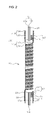
- FIG. 2 shows the leak sensing cable of a leak detection system having power and communication lines according to the present invention, in which the leak sensing cable 10 further includes leak amount sensor lines 17 for sensing a leak amount resulting from a variety of liquids leaking.
- the leak amount sensor lines 17 comprise a leak amount film sensor 18 and an extension line 14 ′ to measure the leak amount.
- the leak amount film sensor 18 may include a humidity fiber (or film) sensor which is typically attached to the front window of a vehicle, and the extension line 14 ′ is connected to the detection controllers 30 along with the leak amount film sensor 18 so that the leak amount signal sensed by the leak amount film sensor 18 is returned to the detection controllers 30 .
- the leak amount sensor lines 17 may be attached to the outer surface (preferably the outer surface between respective leak detection lines 12 ) of the leak sensing cable 10 along with the sensor lines 11 .
- the leak amount sensor lines 17 including the leak amount film sensor 18 and the extension line 14 ′ are connected to the detection controllers 30 in such a manner that one end of each of the leak amount film sensor 18 and the extension line 14 ′ is connected to the detection controllers 30 and the other end of the leak amount film sensor 18 and the other end of the extension line 14 ′ are connected to each other and terminated ( FIGS. 5 and 10 ), according to the principle described for the above sensor lines 11 .
- FIG. 3 is a block diagram showing a leak detection system having power and communication lines in a closed loop according to a preferred embodiment of the present invention
- FIG. 4 is an enlarged view of the portion ‘A’ of FIG. 3 .
- the leak detection system 100 having power and communication lines in a closed loop comprises a leak sensing cable 10 having sensor lines 11 for sensing a leak, detection controllers 30 connected to the sensor lines 11 to detect a leak position signal, and a master controller 20 receiving the detected leak signal from the detection controllers 30 .
- This leak detection system has power and communication lines 15 which are connected to supply power to the detection controllers 30 via the master controller 20 and to transmit the leak signal detected by the detection controllers 30 to the master controller 20 .
- the power and communication lines 15 are embedded inside the leak sensing cable 10 and are wired to connect the master controller 20 and the detection controllers 30 .
- the power and communication lines 15 comprise a positive (+) power and communication line 15 a and a negative ( ⁇ ) power and communication line 15 b.
- the power and communication lines 15 connect the master controller 20 to the detection controllers 30 and are returned to the master controller 20 from the final detection controller 30 thus forming a closed loop.
- the detection controllers 30 are connected to the sensor lines 11 attached to the leak sensing cable 10 , and function to detect the leak position signal sensed by the sensor lines 11 so that such a signal is transmitted to the master controller 20 via the power and communication lines 15 .
- the master controller 20 transmits the leak position signal to a computer 40 , an alarm 50 , etc., from the detection controllers 30 .
- the master controller 20 receives a state information signal (about erroneous operation or failure of the detection controllers 30 ) of the detection controllers 30 via the power and communication lines 15 and transmits such an information signal to the computer 40 .
- the computer 40 functions to store the leak position in response to the leak position signal transmitted from the master controller 20 or the state information of the corresponding detection controller 30 in response to the state information signal, using mmi programs, and to display it on a displayer (not shown) such as a monitor.
- the alarm 50 produces an alarm message (including sound or light) that informs the reception of the leak position signal by the master controller 20 when the leak position signal is transmitted to the master controller 20 .
- the master controller 20 further includes a power supply 60 that supplies power to the detection controllers 30 or the detection controllers 30 and the master controller 20 .
- the energy (power) transferred from the power supply 60 to the master controller 20 is supplied to the detection controllers 30 via the power and communication lines 15 .
- a converter 70 may be further provided between the master controller 20 and the computer 40 , the alarm 50 , and the power supply 60 , so that a communication protocol such as the leak position signal or the like transmitted from the master controller 20 is converted into a signal able to be read by the computer or the power of the power supply 60 is converted into power able to be used by the master controller 20 or the detection controllers 30 .
- the sensor lines 11 of the leak sensing cable 10 comprise two pairs of leak detection lines 12 each pair including a single detection line 13 and a single extension line 14 .
- the sensor lines 11 include a total of four lines comprising two detection lines 13 and two extension lines 14 , among which two leak detection lines 12 in which the single detection line 13 and the single extension line 14 make a pair are wound in the form of a spiral on the outer surface of the leak sensing cable 10 .
- the sensor lines 11 of the leak sensing cable 10 are connected to the detection controllers 30 in such a manner that one end of each of the sensor lines 11 (one end of each of the two pairs of leak detection lines 12 ) is connected to the detection controllers 30 so as to detect the leak position signal by the detection controllers 30 , and the other end thereof is terminated so that the detection lines 13 and the extension lines 14 of respective pairs of leak detection lines 12 are connected (so as to form one line) (the portion ‘A’ of FIG. 3 and FIG. 4 ).
- the leak detection system 100 having power and communication lines in a closed loop includes two or more detection controllers 30 , and these detection controllers 30 are respectively connected to the sensor lines 11 of the leak sensing cable 10 .
- the sensor lines 11 of the leak sensing cable 10 are connected to respective detection controllers 30 and the connection structure of the sensor lines 11 of the leak sensing cable 10 is as above.
- the positive power and communication line 15 a and the negative power and communication line 15 b of the power and communication lines 15 are connected to all the detection controllers 30 using the master controller 20 as the start point and the end point thus forming a closed loop as mentioned above, and are embedded in and connected to the leak sensing cable 10 .
- FIG. 5 shows a leak detection system 100 having power and communication lines in a closed loop, in which the leak sensing cable 10 of FIG. 3 further includes leak amount sensor lines 17
- FIG. 6 is an enlarged view of the portion ‘B’ of FIG. 5 .
- the leak amount sensor lines 17 comprise a leak amount film sensor 18 and an extension line 14 ′, and one end of each of the leak amount sensor 18 and the extension line 14 ′ is further connected to the detection controllers 30 along with the sensor lines 11 , and the other end thereof is wired so as to form one line as was the case for the sensor lines 11 ( FIGS. 5 and 6 ).
- the detection controllers 30 further detect the leak amount signal sensed by the leak amount sensor lines and further transmit it to the master controller 20 , and the master controller 20 transmits this transmitted leak amount signal to the computer 40 , the alarm 50 , etc.
- the computer 40 stores the information about the leak amount along with the information about the leak position, and displays it, and the alarm 50 may display the leak amount in addition to the fact that the leak was detected.
- FIG. 7 is a block diagram showing a leak detection system having power and communication lines in a series according to a preferred embodiment of the present invention
- FIG. 8 is an enlarged view of the portion ‘C’ of FIG. 7
- FIG. 9 is an enlarged view of the portion ‘C′’ of FIG. 7 .
- the leak detection system 200 having power and communication lines in a series comprises a leak sensing cable 10 having sensor lines 11 for sensing a leak, detection controllers 30 connected to the sensor lines 11 to detect a leak position signal, and a master controller 20 receiving the detected leak position signal from the detection controllers 30 .
- the leak detection system 200 includes power and communication lines 15 that supply power to the detection controllers 20 via the master controller 20 and transmit the leak position signal detected by the detection controllers 30 to the master controller 20 , and a common line 16 connected to form a closed circuit of the master controller and the detection controller along with the power and communication lines 15 .
- the configuration and the connection structure of the power and communication lines 15 and the sensor lines 11 are the same as in the above leak detection system having power and communication lines in a closed loop.
- the common line 16 of the leak detection system 200 having power and communication lines in a series allows the power and communication lines 15 to function as communication lines for transmitting the leak position signal from the detection controllers 30 to the master controller 20 , and connects the final detection controller 30 to the master controller 20 along with the positive (+) power and communication line 15 a in the leak detection system 200 having power and communication lines in a series.
- the common line 16 is embedded in the leak sensing cable 10 along with the negative ( ⁇ ) power and communication line 15 b and connects the output terminal (out) of the final detection controller 30 to the master controller 20 , thereby forming a closed circuit in which the power and communication lines 15 may function as the communication line.
- the common line 16 is embedded in the leak sensing cable 10 along with the power and communication lines 15 as shown in FIG. 7 , and is connected to form a closed circuit, but there is no need to embed the power and communication lines 15 and the common line 16 in the leak sensing cable 10 between the final detection controller 30 and the master controller 20 .
- the structure in which the sensor lines 11 of the leak sensing cable 10 are connected to the detection controllers 30 is a wired structure the same as in the leak detection system 100 having power and communication lines in a closed loop.
- the leak detection system 200 having power and communication lines in a series may include two or more detection controllers 30 the same as the leak detection system 100 having power and communication lines in a closed loop.
- the detection controllers 30 are respectively connected to the sensor lines 11 of the leak sensing cable 10 , and the power and communication lines 15 and the common line 16 are connected as shown in FIG. 7 .
- the common line 16 connects the output terminal (out) of the final detection controller 30 among the detection controllers 30 to the master controller 20 along with the positive (+) power and communication line 15 a and the negative power and communication line 15 b to thus form a closed circuit, and thereby enables the power and communication lines 15 to function as communication lines that transmit the leak position signal or the like detected by respective detection controllers 30 to the master controller 20 .
- the leak detection system 200 having power and communication lines in a series may further include a computer 40 , an alarm 50 , a power supply 60 , a converter 70 , etc., which are connected to the master controller 20 , which was described for the leak detection system 100 having power and communication lines in a closed loop.
- FIG. 10 shows a leak detection system 200 having power and communication lines in a series in which the leak sensing cable 10 of FIG. 7 further includes leak amount sensor lines 17
- FIG. 11 is an enlarged view of the portion ‘D’ of FIG. 10
- FIG. 12 is an enlarged view of the portion ‘D′’ of FIG. 10 .
- the leak amount sensor lines 17 comprise a leak amount film sensor 18 and an extension line 14 ′, and one end of each of the leak amount film sensor 18 and the extension line 14 ′ is connected to the detection controllers 30 along with the sensor lines 11 , and the other end thereof is connected so as to form one line as the sensor lines 11 did to thereby form a wired structure ( FIGS. 10 to 12 ).
- the detection controllers 30 further detect the leak amount signal sensed by the leak amount sensor lines to further transmit it to the master controller 20 , and the master controller 20 transmits the above leak amount signal to the computer 40 , the alarm 50 , etc.
- the computer 40 stores the information about the leak amount along with the information about the leak position and displays it on a monitor, etc., and the alarm 50 displays the leak amount in addition to the fact that the leak was detected.
- the leak detection system having power and communication lines according to the present invention may be installed to hot water supply pipes or cooling water supply pipes of regional heating corporations, semiconductor plants, museums, telephone offices, general buildings, etc., in order to detect the leak.
- the master controller 20 may typically manage about 100 detection controllers 30 and enables leak detection over a maximum distance of 24 km.
- either the leak detection system 100 having power and communication lines in a closed loop or the leak detection system 200 having power and communication lines in a series may be installed depending on the form and the characteristics of a region that requires the installation of a leak detection system.
- a leak sensing cable further includes power and communication lines, and thereby the leak detection system has the power and communication lines able to transmit a leak position signal between detection controllers and a master controller while supplying power to the detection controllers and the master controller.
- the leak detection system having power and communication lines can be easily installed depending on the characteristics of a region that requires the installation of a leak detection system.
- the leak detection system has power and communication lines able to transmit a leak position signal and a leak amount signal between the detection controllers and the master controller while supplying power to the detection controllers and the master controller.
Abstract
Description
- This application claims foreign priority under Paris Convention and 35 U.S.C. §119 to Korean Patent Application No. 10-2010-0075756, filed Aug. 6, 2010 with the Korean Intellectual Property Office.
- 1. Technical Field
- The present invention relates to a leak detection system, and, more particularly, to a leak detection system having power and communication lines embedded in a leak sensing cable.
- 2. Description of the Related Art
- This invention pertains to a leak detection system.
- A conventional leak detection system includes a leak sensing cable having sensor lines for sensing a leak, detection controllers connected to the sensor lines of the leak sensing cable to detect a leak position signal, and a master controller receiving the leak position signal from the detection controllers to process it.
- However, the conventional leak detection system is problematic because a power line for supplying power necessary for operating the detection controllers or the master controller has to be additionally provided, and a communication line for transmitting the leak position signal detected by the detection controllers to the master controller also must be additionally provided, undesirably making it difficult to install and manage the leak detection system and increasing the installation cost.
- Specifically, the conventional leak detection system is undesirably configured because the power system for supplying power to the detection controllers and the master controller and the communication system for transmitting the leak position signal between the detection controllers and the master controller have to be separately provided.
- Accordingly, the present invention has been made keeping in mind the problems occurring in the related art and an object of the present invention is to provide a leak detection system having power and communication lines, in which a leak sensing cable having sensor lines for sensing a leak position attached to the outer surface thereof further includes the power and communication lines, thereby enabling detection controllers and a master controller to be powered and simultaneously the leak position signal to be transmitted between the detection controllers and the master controller.
- Another object of the present invention is to provide a leak detection system having power and communication lines, which is provided in a closed loop or in a series using a leak sensing cable having not only sensor lines but also power and communication lines, whereby the leak detection system having power and communication lines may be easily provided depending on the characteristics of a region that requires the installation of a leak detection system.
- A further object of the present invention is to provide a leak detection system having power and communication lines, in which a leak sensing cable having sensor lines for sensing a leak position attached to the outer surface thereof further includes the power and communication lines, and leak amount sensor lines are further attached to the outer surface of the cable to sense the leak amount, thereby enabling detection controllers and a master controller to be powered and simultaneously the leak position signal and the leak amount signal to be transmitted between the detection controllers and the master controller.
- In order to accomplish the above objects, an aspect of the present invention provides a leak detection system having power and communication lines, comprising a leak sensing cable having sensor lines for sensing a leak, at least one detection controller connected to the sensor lines to detect a leak position signal, and a master controller receiving the detected leak position signal from the detection controller, wherein the leak sensing cable includes the power and communication lines that are wired to supply power to the detection controller via the master controller and to transmit the leak position signal from the detection controller to the master controller, and a computer for storing the leak position signal received by the master controller and displaying it on a monitor is provided.
- In this aspect, the power and communication lines may be embedded in the leak sensing cable and may be connected to the master controller and the detection controller.
- In this aspect, the power and communication lines may comprise a positive (+) power and communication line and a negative (−) power and communication line.
- In this aspect, the positive power and communication line and the negative power and communication line may be connected to the detection controller using the master controller as a start point and an end point thus forming a closed loop.
- In this aspect, the at least one detection controller may comprise two or more detection controllers, and the detection controllers may be respectively connected to the sensor lines.
- In this aspect, the sensor lines may comprise two pairs of leak detection lines each pair comprising a single detection line and a single extension line, and one end of each of the detection lines and the extension lines may be connected to the detection controllers, and the other end thereof may be terminated so that the detection lines and the extension lines of respective pairs of leak detection lines are connected to each other.
- In this aspect, the leak detection system may further comprise an alarm for informing of reception of the leak position signal by the master controller when the leak position signal is transmitted to the master controller.
- In this aspect, the leak sensing cable may further include leak amount sensor lines for sensing a leak amount, the detection controller may be connected to the leak amount sensor lines to further detect a leak amount signal, and the master controller may further receive the detected leak amount signal from the detection controller.
- In this aspect, the leak amount sensor lines may comprise a leak amount film sensor and an extension line, and one end of each of the leak amount film sensor and the extension line may be connected to the detection controller, and the other end of the leak amount film sensor and the other end of the extension line may be terminated so as to be connected to each other.
- In this aspect, the leak amount film sensor and the extension line may be attached to an outer surface of the leak sensing cable.
- Another aspect of the present invention provides a leak detection system having power and communication lines, comprising a leak sensing cable having sensor lines for sensing a leak, at least one detection controller connected to the sensor lines to detect a leak position signal, and a master controller receiving the detected leak position signal from the detection controller, wherein the leak sensing cable includes the power and communication lines that supply power to the detection controller via the master controller and transmit the leak position signal from the detection controller to the master controller, and a common line wired to form a closed circuit of the master controller and the detection controller along with the power and communication lines.
- In this aspect, the power and communication lines and the common line may be embedded in the leak sensing cable, and may be connected to the master controller and the detection controller.
- In this aspect, the power and communication lines may comprise a positive (+) power and communication line and a negative (−) power and communication line.
- In this aspect, the at least one detection controller may comprise two or more detection controllers, and the detection controllers may be respectively connected to the sensor lines.
- In this aspect, the sensor lines may comprise two pairs of leak detection lines each pair comprising a single detection line and a single extension line, and one end of each of the detection lines and the extensions may be connected to the detection controllers, and the other end thereof may be terminated so that the detection lines and the extension lines of respective pairs of leak detection lines are connected to each other.
- In this aspect, the leak detection system may further comprise a computer for storing the leak position signal received by the master controller and displaying it on a monitor.
- In this aspect, the leak detection system may further comprise an alarm for informing of reception of the leak position signal by the master controller when the leak position signal is transmitted to the master controller.
- In this aspect, the leak sensing cable may further include leak amount sensor lines for sensing a leak amount, the detection controller may be connected to the leak amount sensor lines to further detect a leak amount signal, and the master controller may further receive the detected leak amount signal from the detection controller.
- In this aspect, the leak amount sensor lines may comprise a leak amount film sensor and an extension line, and one end of each of the leak amount film sensor and the extension line may be connected to the detection controller, and the other end of the leak amount film sensor and the other end of the extension line may be terminated so as to be connected to each other.
- In this aspect, the leak amount film sensor and the extension line may be attached to an outer surface of the leak sensing cable.
- The features and advantages of the present invention will be more clearly understood from the following detailed description taken in conjunction with the accompanying drawings, in which:
-
FIGS. 1 and 2 are views showing a leak sensing cable; -
FIG. 3 is a block diagram showing a leak detection system having power and communication lines according to an embodiment of the present invention; -
FIG. 4 is an enlarged view of the portion ‘A’ ofFIG. 3 ; -
FIG. 5 is a block diagram showing a leak detection system having power and communication lines, in which the leak sensing cable ofFIG. 3 further includes leak amount sensor lines; -
FIG. 6 is an enlarged view of the portion ‘B’ ofFIG. 5 ; -
FIG. 7 is a block diagram showing a leak detection system having power and communication lines according to another embodiment of the present invention; -
FIGS. 8 and 9 are enlarged views of the portions ‘C’ and ‘C′’ ofFIG. 7 , respectively; -
FIG. 10 is a block diagram showing a leak detection system having power and communication lines, in which the leak sensing cable ofFIG. 7 further includes leak amount sensor lines; and -
FIGS. 11 and 12 show enlarged views of the portions ‘D’ and ‘D′’ ofFIG. 10 , respectively. - Hereinafter, embodiments of the present invention of a leak detection system having power and communication lines will be described in detail while referring to the accompanying drawings. Throughout the drawings, the same reference numerals are used to refer to the same or similar elements.
-
FIG. 1 shows the leak sensing cable of a leak detection system having power and communication lines according to the present invention. - The
leak sensing cable 10 includessensor lines 11 that are attached to the outer surface thereof so as to come into contact with the outside and so sense a leak, and power andcommunication lines 15 are embedded in theleak sensing cable 10. - The
sensor lines 11 comprise two pairs ofleak detection lines 12 each pair having asingle detection line 13 and asingle extension line 14. - The
detection lines 13 are made of a conductive polymer which detects a variety of liquids such as a liquid, an acidic or alkaline solution, oil and so on and has a predetermined resistance in proportion to the length. - When the variety of liquids are detected at specific positions of the
detection lines 13 due to leaking water or oil, there occurs a difference in potential (voltage) because of an electrochemical reaction between twodetection lines 13 made of a conductive polymer (which is particularly a conductive polymer able to be penetrated by a variety of liquids). Thereby, changes in resistance and a difference in feedback current todetection controllers 30 connected to thesensor lines 11 are controlled by thedetection controllers 30, and are calculated, thus determining the accurate leak position (reference to conventional leak sensing cables such as Model Nos. TT1000, TT3000, TT7000, etc.). - As such, one end of each of the
detection lines 13 and theextension lines 14 of theleak detection lines 12 is connected to thedetection controllers 30, and the other end thereof is terminated so that thedetection lines 13 and theextension lines 14 of respective pairs ofleak detection lines 12 are connected to each other (so as to make one line). Thedetection lines 13 have their own resistance and should be subjected to termination resistance treatment. - The power and
communication lines 15 are used for providing the power and communication necessary for the leak detection system, and comprise a positive (+) power andcommunication line 15 a used as a positive (+) line of power and a positive (+) line of communication, and a negative (−) power andcommunication line 15 b used as a negative (−) line of power and a negative (−) line of communication. - The power and
communication lines 15 function to supply power to thedetection controllers 30, and to transfer leak position information to themaster controller 20 from thedetection controllers 30 that has been obtained from thesensor lines 11. - The power and
communication lines 15 are preferably embedded in the leak sensing cable having foursensor lines 11 attached to the outer surface thereof to sense a leak. - The leak detection system having power and communication lines according to the present invention is exemplified by a
leak detection system 100 having power and communication lines in a closed loop (FIGS. 3 and 5 ) in which the power andcommunication lines 15 are connected to thedetection controllers 30 using themaster controller 20 as a start point and an end point so that thefinal detection controller 30 among thedetection controllers 30 is returned toward themaster controller 20, and a leak detection system 200 having power and communication lines in a series (FIGS. 7 and 10 ) in whichdetection controllers 30 are disposed in a series relative to themaster controller 20. - As such, in the case of the leak detection system 200 having power and communication lines in a series (
FIGS. 7 and 10 ), acommon line 16, in addition to the power andcommunication lines 15, is further contained in theleak sensing cable 10. - The
common line 16 enables the power andcommunication lines 15 to function as communication lines. In the leak detection system 200 having power and communication lines in a series, thecommon line 16 connects thefinal detection controller 30 to themaster controller 20 along with the positive (+) power andcommunication line 15 a, which is specified later. -
FIG. 2 shows the leak sensing cable of a leak detection system having power and communication lines according to the present invention, in which theleak sensing cable 10 further includes leakamount sensor lines 17 for sensing a leak amount resulting from a variety of liquids leaking. - The leak
amount sensor lines 17 comprise a leakamount film sensor 18 and anextension line 14′ to measure the leak amount. - The leak
amount film sensor 18 may include a humidity fiber (or film) sensor which is typically attached to the front window of a vehicle, and theextension line 14′ is connected to thedetection controllers 30 along with the leakamount film sensor 18 so that the leak amount signal sensed by the leakamount film sensor 18 is returned to thedetection controllers 30. - As such, the leak
amount sensor lines 17 may be attached to the outer surface (preferably the outer surface between respective leak detection lines 12) of theleak sensing cable 10 along with the sensor lines 11. - The leak
amount sensor lines 17 including the leakamount film sensor 18 and theextension line 14′ are connected to thedetection controllers 30 in such a manner that one end of each of the leakamount film sensor 18 and theextension line 14′ is connected to thedetection controllers 30 and the other end of the leakamount film sensor 18 and the other end of theextension line 14′ are connected to each other and terminated (FIGS. 5 and 10 ), according to the principle described for the above sensor lines 11. -
FIG. 3 is a block diagram showing a leak detection system having power and communication lines in a closed loop according to a preferred embodiment of the present invention, andFIG. 4 is an enlarged view of the portion ‘A’ ofFIG. 3 . - The
leak detection system 100 having power and communication lines in a closed loop comprises aleak sensing cable 10 havingsensor lines 11 for sensing a leak,detection controllers 30 connected to thesensor lines 11 to detect a leak position signal, and amaster controller 20 receiving the detected leak signal from thedetection controllers 30. This leak detection system has power andcommunication lines 15 which are connected to supply power to thedetection controllers 30 via themaster controller 20 and to transmit the leak signal detected by thedetection controllers 30 to themaster controller 20. - The power and
communication lines 15 are embedded inside theleak sensing cable 10 and are wired to connect themaster controller 20 and thedetection controllers 30. - The power and
communication lines 15 comprise a positive (+) power andcommunication line 15 a and a negative (−) power andcommunication line 15 b. - As shown in
FIG. 3 , the power andcommunication lines 15 connect themaster controller 20 to thedetection controllers 30 and are returned to themaster controller 20 from thefinal detection controller 30 thus forming a closed loop. - As such, the
detection controllers 30 are connected to thesensor lines 11 attached to theleak sensing cable 10, and function to detect the leak position signal sensed by thesensor lines 11 so that such a signal is transmitted to themaster controller 20 via the power and communication lines 15. - The
master controller 20 transmits the leak position signal to acomputer 40, analarm 50, etc., from thedetection controllers 30. - The
master controller 20 receives a state information signal (about erroneous operation or failure of the detection controllers 30) of thedetection controllers 30 via the power andcommunication lines 15 and transmits such an information signal to thecomputer 40. - The
computer 40 functions to store the leak position in response to the leak position signal transmitted from themaster controller 20 or the state information of the correspondingdetection controller 30 in response to the state information signal, using mmi programs, and to display it on a displayer (not shown) such as a monitor. - The
alarm 50 produces an alarm message (including sound or light) that informs the reception of the leak position signal by themaster controller 20 when the leak position signal is transmitted to themaster controller 20. - As such, the
master controller 20 further includes apower supply 60 that supplies power to thedetection controllers 30 or thedetection controllers 30 and themaster controller 20. - The energy (power) transferred from the
power supply 60 to themaster controller 20 is supplied to thedetection controllers 30 via the power and communication lines 15. - As such, a
converter 70 may be further provided between themaster controller 20 and thecomputer 40, thealarm 50, and thepower supply 60, so that a communication protocol such as the leak position signal or the like transmitted from themaster controller 20 is converted into a signal able to be read by the computer or the power of thepower supply 60 is converted into power able to be used by themaster controller 20 or thedetection controllers 30. - The sensor lines 11 of the
leak sensing cable 10 comprise two pairs ofleak detection lines 12 each pair including asingle detection line 13 and asingle extension line 14. - The sensor lines 11 include a total of four lines comprising two
detection lines 13 and twoextension lines 14, among which twoleak detection lines 12 in which thesingle detection line 13 and thesingle extension line 14 make a pair are wound in the form of a spiral on the outer surface of theleak sensing cable 10. - The sensor lines 11 of the
leak sensing cable 10 are connected to thedetection controllers 30 in such a manner that one end of each of the sensor lines 11 (one end of each of the two pairs of leak detection lines 12) is connected to thedetection controllers 30 so as to detect the leak position signal by thedetection controllers 30, and the other end thereof is terminated so that thedetection lines 13 and the extension lines 14 of respective pairs ofleak detection lines 12 are connected (so as to form one line) (the portion ‘A’ ofFIG. 3 andFIG. 4 ). - The
leak detection system 100 having power and communication lines in a closed loop includes two ormore detection controllers 30, and thesedetection controllers 30 are respectively connected to thesensor lines 11 of theleak sensing cable 10. - The sensor lines 11 of the
leak sensing cable 10 are connected torespective detection controllers 30 and the connection structure of thesensor lines 11 of theleak sensing cable 10 is as above. - As such, the positive power and
communication line 15 a and the negative power andcommunication line 15 b of the power andcommunication lines 15 are connected to all thedetection controllers 30 using themaster controller 20 as the start point and the end point thus forming a closed loop as mentioned above, and are embedded in and connected to theleak sensing cable 10. -
FIG. 5 shows aleak detection system 100 having power and communication lines in a closed loop, in which theleak sensing cable 10 ofFIG. 3 further includes leakamount sensor lines 17, andFIG. 6 is an enlarged view of the portion ‘B’ ofFIG. 5 . - The leak
amount sensor lines 17 comprise a leakamount film sensor 18 and anextension line 14′, and one end of each of theleak amount sensor 18 and theextension line 14′ is further connected to thedetection controllers 30 along with thesensor lines 11, and the other end thereof is wired so as to form one line as was the case for the sensor lines 11 (FIGS. 5 and 6 ). - As such, the
detection controllers 30 further detect the leak amount signal sensed by the leak amount sensor lines and further transmit it to themaster controller 20, and themaster controller 20 transmits this transmitted leak amount signal to thecomputer 40, thealarm 50, etc. - The
computer 40 stores the information about the leak amount along with the information about the leak position, and displays it, and thealarm 50 may display the leak amount in addition to the fact that the leak was detected. -
FIG. 7 is a block diagram showing a leak detection system having power and communication lines in a series according to a preferred embodiment of the present invention, andFIG. 8 is an enlarged view of the portion ‘C’ ofFIG. 7 andFIG. 9 is an enlarged view of the portion ‘C′’ ofFIG. 7 . - The leak detection system 200 having power and communication lines in a series comprises a
leak sensing cable 10 havingsensor lines 11 for sensing a leak,detection controllers 30 connected to thesensor lines 11 to detect a leak position signal, and amaster controller 20 receiving the detected leak position signal from thedetection controllers 30. Also, the leak detection system 200 includes power andcommunication lines 15 that supply power to thedetection controllers 20 via themaster controller 20 and transmit the leak position signal detected by thedetection controllers 30 to themaster controller 20, and acommon line 16 connected to form a closed circuit of the master controller and the detection controller along with the power and communication lines 15. - The configuration and the connection structure of the power and
communication lines 15 and thesensor lines 11 are the same as in the above leak detection system having power and communication lines in a closed loop. - As shown in
FIG. 7 , thecommon line 16 of the leak detection system 200 having power and communication lines in a series allows the power andcommunication lines 15 to function as communication lines for transmitting the leak position signal from thedetection controllers 30 to themaster controller 20, and connects thefinal detection controller 30 to themaster controller 20 along with the positive (+) power andcommunication line 15 a in the leak detection system 200 having power and communication lines in a series. - The
common line 16 is embedded in theleak sensing cable 10 along with the negative (−) power andcommunication line 15 b and connects the output terminal (out) of thefinal detection controller 30 to themaster controller 20, thereby forming a closed circuit in which the power andcommunication lines 15 may function as the communication line. - In the leak detection system 200 having power and communication lines in a series, the
common line 16 is embedded in theleak sensing cable 10 along with the power andcommunication lines 15 as shown inFIG. 7 , and is connected to form a closed circuit, but there is no need to embed the power andcommunication lines 15 and thecommon line 16 in theleak sensing cable 10 between thefinal detection controller 30 and themaster controller 20. - The structure in which the
sensor lines 11 of theleak sensing cable 10 are connected to thedetection controllers 30 is a wired structure the same as in theleak detection system 100 having power and communication lines in a closed loop. - Also the leak detection system 200 having power and communication lines in a series may include two or
more detection controllers 30 the same as theleak detection system 100 having power and communication lines in a closed loop. - In this case, the
detection controllers 30 are respectively connected to thesensor lines 11 of theleak sensing cable 10, and the power andcommunication lines 15 and thecommon line 16 are connected as shown inFIG. 7 . - The
common line 16 connects the output terminal (out) of thefinal detection controller 30 among thedetection controllers 30 to themaster controller 20 along with the positive (+) power andcommunication line 15 a and the negative power andcommunication line 15 b to thus form a closed circuit, and thereby enables the power andcommunication lines 15 to function as communication lines that transmit the leak position signal or the like detected byrespective detection controllers 30 to themaster controller 20. - The leak detection system 200 having power and communication lines in a series may further include a
computer 40, analarm 50, apower supply 60, aconverter 70, etc., which are connected to themaster controller 20, which was described for theleak detection system 100 having power and communication lines in a closed loop. -
FIG. 10 shows a leak detection system 200 having power and communication lines in a series in which theleak sensing cable 10 ofFIG. 7 further includes leakamount sensor lines 17, andFIG. 11 is an enlarged view of the portion ‘D’ ofFIG. 10 andFIG. 12 is an enlarged view of the portion ‘D′’ ofFIG. 10 . - The leak
amount sensor lines 17 comprise a leakamount film sensor 18 and anextension line 14′, and one end of each of the leakamount film sensor 18 and theextension line 14′ is connected to thedetection controllers 30 along with thesensor lines 11, and the other end thereof is connected so as to form one line as thesensor lines 11 did to thereby form a wired structure (FIGS. 10 to 12 ). - The
detection controllers 30 further detect the leak amount signal sensed by the leak amount sensor lines to further transmit it to themaster controller 20, and themaster controller 20 transmits the above leak amount signal to thecomputer 40, thealarm 50, etc. - The
computer 40 stores the information about the leak amount along with the information about the leak position and displays it on a monitor, etc., and thealarm 50 displays the leak amount in addition to the fact that the leak was detected. - The leak detection system having power and communication lines according to the present invention may be installed to hot water supply pipes or cooling water supply pipes of regional heating corporations, semiconductor plants, museums, telephone offices, general buildings, etc., in order to detect the leak.
- The
master controller 20 may typically manage about 100detection controllers 30 and enables leak detection over a maximum distance of 24 km. - As the leak detection system having power and communication lines according to the present invention, either the
leak detection system 100 having power and communication lines in a closed loop or the leak detection system 200 having power and communication lines in a series may be installed depending on the form and the characteristics of a region that requires the installation of a leak detection system. - As described hereinbefore, the present invention provides a leak detection system having power and communication lines. \ According to the present invention, a leak sensing cable further includes power and communication lines, and thereby the leak detection system has the power and communication lines able to transmit a leak position signal between detection controllers and a master controller while supplying power to the detection controllers and the master controller.
- Also according to the present invention, the leak detection system having power and communication lines can be easily installed depending on the characteristics of a region that requires the installation of a leak detection system.
- Also according to the present invention, the leak detection system has power and communication lines able to transmit a leak position signal and a leak amount signal between the detection controllers and the master controller while supplying power to the detection controllers and the master controller.
- Although the embodiments of the present invention have been disclosed for illustrative purposes, those skilled in the art will appreciate that a variety of different modifications, additions and substitutions are possible, without departing from the scope and spirit of the invention as disclosed in the accompanying claims. Accordingly, such modifications, additions and substitutions should also be understood as falling within the scope of the present invention.
Claims (20)
Applications Claiming Priority (2)
| Application Number | Priority Date | Filing Date | Title |
|---|---|---|---|
| KR10-2010-0075756 | 2010-08-06 | ||
| KR1020100075756A KR101006710B1 (en) | 2010-08-06 | 2010-08-06 | Leak detection system |
Publications (2)
| Publication Number | Publication Date |
|---|---|
| US20120032811A1 true US20120032811A1 (en) | 2012-02-09 |
| US8786451B2 US8786451B2 (en) | 2014-07-22 |
Family
ID=43615946
Family Applications (1)
| Application Number | Title | Priority Date | Filing Date |
|---|---|---|---|
| US13/196,347 Active 2032-09-24 US8786451B2 (en) | 2010-08-06 | 2011-08-02 | Leak detection system having power and communication lines |
Country Status (2)
| Country | Link |
|---|---|
| US (1) | US8786451B2 (en) |
| KR (1) | KR101006710B1 (en) |
Cited By (3)
| Publication number | Priority date | Publication date | Assignee | Title |
|---|---|---|---|---|
| FR2998753A1 (en) * | 2012-11-28 | 2014-05-30 | Ttk | MODULE, CIRCUIT AND COMMUNICATION METHOD FOR DETECTION DEVICE AND SENSOR COMPRISING SUCH A MODULE. |
| US20150306720A1 (en) * | 2012-12-20 | 2015-10-29 | Mitsubishi Heavy Industries , Ltd. | Control device for working device, working device, control program for working device, control method for working device, and working method |
| US20170089302A1 (en) * | 2015-09-25 | 2017-03-30 | GM Global Technology Operations LLC | Systems and methods for detecting damage in a positive crankcase ventilation tube |
Families Citing this family (6)
| Publication number | Priority date | Publication date | Assignee | Title |
|---|---|---|---|---|
| US8967186B2 (en) * | 2012-09-13 | 2015-03-03 | Jeffrey Scott Adler | Fluid spill containment, location, and real time notification device and system |
| KR101286316B1 (en) * | 2013-03-06 | 2013-07-19 | 주식회사 창성에이스산업 | Cable and system for heat and liquid leakage sensing |
| KR101592099B1 (en) | 2014-05-27 | 2016-02-04 | 김광열 | Leakage detection cable a and leakage detection system using the cable |
| US10761954B2 (en) | 2015-10-27 | 2020-09-01 | Hewlett Packard Enterprise Development Lp | Sensor detection architecture |
| KR101856619B1 (en) | 2016-06-08 | 2018-05-10 | 심충식 | Leak liquid sensing cable and manufacturing method thereof |
| US11016001B2 (en) * | 2018-10-01 | 2021-05-25 | Dell Products L.P. | Systems and methods for leak detection in liquid-cooled information handling systems |
Citations (12)
| Publication number | Priority date | Publication date | Assignee | Title |
|---|---|---|---|---|
| US4206632A (en) * | 1979-01-23 | 1980-06-10 | Hirosuke Suzuki | Liquid detecting device |
| US4797621A (en) * | 1987-07-08 | 1989-01-10 | Midwesco, Inc. | Leak detector and locator utilizing time domain reflectometry and sampling techniques |
| US4910998A (en) * | 1987-05-01 | 1990-03-27 | Andrew Corporation | Fluid detection system and method having a coaxial cable with solid, stranded dielectric elements |
| US5159276A (en) * | 1991-07-08 | 1992-10-27 | W. L. Gore & Associates, Inc. | Capacitance measuring circuit and method for liquid leak detection by measuring charging time |
| US5177996A (en) * | 1991-11-21 | 1993-01-12 | W. L. Gore & Associates, Inc. | Liquid leak detection cable |
| US5272646A (en) * | 1991-04-11 | 1993-12-21 | Farmer Edward J | Method for locating leaks in a fluid pipeline and apparatus therefore |
| US5334970A (en) * | 1992-05-21 | 1994-08-02 | Midwesco, Inc. | Alarm system |
| US5410255A (en) * | 1993-05-07 | 1995-04-25 | Perma-Pipe, Inc. | Method and apparatus for detecting and distinguishing leaks using reflectometry and conductivity tests |
| US5883815A (en) * | 1996-06-20 | 1999-03-16 | Drakulich; Dushan | Leak detection system |
| US6526807B1 (en) * | 1998-06-18 | 2003-03-04 | Joseph Doumit | Early warning water leak detection system |
| US20040098212A1 (en) * | 2002-03-14 | 2004-05-20 | Hong In Sik | Water leakage detecting system for liquid pipe and method thereof |
| US20120027927A1 (en) * | 2008-06-06 | 2012-02-02 | Raymond Donald M | Twisted leak detection cable |
Family Cites Families (2)
| Publication number | Priority date | Publication date | Assignee | Title |
|---|---|---|---|---|
| KR100450507B1 (en) * | 2002-10-15 | 2004-10-01 | 주식회사 팬택 | Apparatus For Compensating Real Time Clock Timing For Mobile Communication |
| KR200433613Y1 (en) * | 2006-09-27 | 2006-12-11 | (주)포스프로 | Sensor cable for water leakage and sensing system using it |
-
2010
- 2010-08-06 KR KR1020100075756A patent/KR101006710B1/en active IP Right Grant
-
2011
- 2011-08-02 US US13/196,347 patent/US8786451B2/en active Active
Patent Citations (12)
| Publication number | Priority date | Publication date | Assignee | Title |
|---|---|---|---|---|
| US4206632A (en) * | 1979-01-23 | 1980-06-10 | Hirosuke Suzuki | Liquid detecting device |
| US4910998A (en) * | 1987-05-01 | 1990-03-27 | Andrew Corporation | Fluid detection system and method having a coaxial cable with solid, stranded dielectric elements |
| US4797621A (en) * | 1987-07-08 | 1989-01-10 | Midwesco, Inc. | Leak detector and locator utilizing time domain reflectometry and sampling techniques |
| US5272646A (en) * | 1991-04-11 | 1993-12-21 | Farmer Edward J | Method for locating leaks in a fluid pipeline and apparatus therefore |
| US5159276A (en) * | 1991-07-08 | 1992-10-27 | W. L. Gore & Associates, Inc. | Capacitance measuring circuit and method for liquid leak detection by measuring charging time |
| US5177996A (en) * | 1991-11-21 | 1993-01-12 | W. L. Gore & Associates, Inc. | Liquid leak detection cable |
| US5334970A (en) * | 1992-05-21 | 1994-08-02 | Midwesco, Inc. | Alarm system |
| US5410255A (en) * | 1993-05-07 | 1995-04-25 | Perma-Pipe, Inc. | Method and apparatus for detecting and distinguishing leaks using reflectometry and conductivity tests |
| US5883815A (en) * | 1996-06-20 | 1999-03-16 | Drakulich; Dushan | Leak detection system |
| US6526807B1 (en) * | 1998-06-18 | 2003-03-04 | Joseph Doumit | Early warning water leak detection system |
| US20040098212A1 (en) * | 2002-03-14 | 2004-05-20 | Hong In Sik | Water leakage detecting system for liquid pipe and method thereof |
| US20120027927A1 (en) * | 2008-06-06 | 2012-02-02 | Raymond Donald M | Twisted leak detection cable |
Cited By (6)
| Publication number | Priority date | Publication date | Assignee | Title |
|---|---|---|---|---|
| FR2998753A1 (en) * | 2012-11-28 | 2014-05-30 | Ttk | MODULE, CIRCUIT AND COMMUNICATION METHOD FOR DETECTION DEVICE AND SENSOR COMPRISING SUCH A MODULE. |
| WO2014083104A1 (en) * | 2012-11-28 | 2014-06-05 | Ttk | Module, circuit and method of communication for detection device and sensor comprising such a module, in particular for explosive atmosphere |
| US9621965B2 (en) | 2012-11-28 | 2017-04-11 | Ttk | Module, circuit and method of communication for detection device and sensor comprising such a module, in particular for explosive atmosphere |
| US20150306720A1 (en) * | 2012-12-20 | 2015-10-29 | Mitsubishi Heavy Industries , Ltd. | Control device for working device, working device, control program for working device, control method for working device, and working method |
| US20170089302A1 (en) * | 2015-09-25 | 2017-03-30 | GM Global Technology Operations LLC | Systems and methods for detecting damage in a positive crankcase ventilation tube |
| US9828950B2 (en) * | 2015-09-25 | 2017-11-28 | GM Global Technology Operations LLC | Systems and methods for detecting damage in a positive crankcase ventilation tube |
Also Published As
| Publication number | Publication date |
|---|---|
| KR101006710B1 (en) | 2011-01-10 |
| US8786451B2 (en) | 2014-07-22 |
Similar Documents
| Publication | Publication Date | Title |
|---|---|---|
| US8786451B2 (en) | Leak detection system having power and communication lines | |
| US20150116118A1 (en) | Leak detection device and remote monitoring system using the same | |
| KR101250243B1 (en) | Apparatus and Method for Measuring the Length of a Pipe | |
| KR101287627B1 (en) | detecting system for disconnection of distribution line | |
| US10763697B2 (en) | System and method of controlling supply of electrical power | |
| CN111404273A (en) | Remote sensing monitoring system for overhead line | |
| KR101400886B1 (en) | 3d distributed underground temperature measuring system | |
| KR101109753B1 (en) | A system for sensing a water leakage | |
| JP6205357B2 (en) | Communication method for setting and / or query purposes and system implementing the same | |
| KR20110030735A (en) | Water pipe hydrostat | |
| JP2015195646A (en) | Measurement device for distribution board, and anti-earthquake system employing the same | |
| JP6059164B2 (en) | Optical path switching device and communication method | |
| SE1100843A1 (en) | Climate control system | |
| JP6832643B2 (en) | Power supply system | |
| KR20150087467A (en) | Safety administration system of aseismic reinforcement structure with real-time and remote mode using internet | |
| US10071255B2 (en) | Monitoring system | |
| TWI580974B (en) | Cable joint detection systems, devices, and modules | |
| CN203274942U (en) | Plug-in type multipoint temperature measuring device for power cables | |
| CN114978318B (en) | Online electronic seal system | |
| JP2014186709A (en) | Temperature monitoring system | |
| RU2011137661A (en) | CABLE CONNECTIONS MONITORING SYSTEM USING A REFLECTOMETER AND NETWORK DEVICE | |
| CN209118119U (en) | A kind of secondary water-supply equipment remote on-line monitoring system based on GPRS communication | |
| CN208420770U (en) | A kind of intelligence pH value measuring system | |
| KR101187446B1 (en) | Remote reading system | |
| CN202614939U (en) | A directly-emitting object detecting system |
Legal Events
| Date | Code | Title | Description |
|---|---|---|---|
| AS | Assignment |
Owner name: CHANG SUNG ACE CO., LTD.,, KOREA, REPUBLIC OF Free format text: ASSIGNMENT OF ASSIGNORS INTEREST;ASSIGNOR:LEE, YEU YONG;REEL/FRAME:026688/0091 Effective date: 20110630 |
|
| STCF | Information on status: patent grant |
Free format text: PATENTED CASE |
|
| MAFP | Maintenance fee payment |
Free format text: PAYMENT OF MAINTENANCE FEE, 4TH YR, SMALL ENTITY (ORIGINAL EVENT CODE: M2551) Year of fee payment: 4 |
|
| MAFP | Maintenance fee payment |
Free format text: PAYMENT OF MAINTENANCE FEE, 8TH YR, SMALL ENTITY (ORIGINAL EVENT CODE: M2552); ENTITY STATUS OF PATENT OWNER: SMALL ENTITY Year of fee payment: 8 |