CROSS-REFERENCE TO RELATED APPLICATIONS
-
The present application is one of two patent applications claiming priority from U.S. provisional patent application No. 61/089,617. The present patent application relates to the usage of cyclic prefixes, whereas the other patent application relates to techniques for space-time coding. The techniques described in the respective two patent applications are independent since either can be used without the other, although it is equally possible to construct systems which combine techniques from the respective two patent applications.
FIELD OF THE INVENTION
-
This invention relates to methods and systems for implementing cyclic prefixes in a wireless communication channel comprising a relay station capable of performing information coding, particularly but not exclusively, analog space-time coding.
BACKGROUND OF THE INVENTION
-
Wireless relays have shown potential for extending communication range and providing good quality of experience. In a typical wireless communication system utilizing relays, the relay station would be time shared between different sources and destination. In such a scenario, the relay station needs to estimate the Angular Carrier Frequency Offset (ACFO) present between each pair of source and relay antennae (denoted ACFO φr). The ACFO that is present between each pair of relay and destination antennae (denoted ACFO φd) will be compensated for at the destination.
-
Joint compensation of the source to relay and relay to destination ACFO is not possible in the prior art. Compensation for the source to relay ACFO φr can thus only be performed at the relay station. The relay station of the prior art will need to estimate and compensate the ACFO for each source-and-relay pair and this complicates the relay station hardware and increases the power required by the relay station.
-
Implementations of analog space-time coding (ASTC) in the prior art also have the limitation that the transmission channel has to be flat fading. This is because inter-symbol interference (ISI) results when the transmission channel has frequency selective fading. The insertion of a cyclic prefix (CP) can be used to mitigate against ISI. The cyclic prefix inserted should preferably be of a length greater than that of the channel impulse response (CIR).
-
Typical implementations of ASTC also require that the samples within a signal be re-ordered when performing the coding.
-
It is an object of the present invention to provide a method for implementing cyclic prefixes and compensating for the channel effects of a wireless communication channel, which addresses at least one of the problems of the prior art and/or to provide the public with a useful choice.
SUMMARY OF THE INVENTION
-
In general terms, the present invention relates to transmitting data though a wireless communication channel from a source to a destination via a relay station having multiple antennae. The relay station receives a message from the source containing the data and a first cyclic prefix. It does this using each of its antennae, so producing multiple respective received signals. In a first aspect of the invention, the relay station removes the first cyclic prefix from the received signals, replacing it with a new one. In a second aspect of the invention, the relay station removes only a portion of the first cyclic prefix. In either case, the relay station may apply space-time coding to generate second signals, which it transmits to the destination, which extracts the data. A further aspect of the invention relates to estimating parameters of the channel, to enable the destination to decode the data.
-
The invention may be expressed alternatively as an integrated circuit configured to enable the above mentioned aspects of the invention.
-
The cyclic prefix schemes of the present invention do not require that the transmission channels be flat fading.
BRIEF DESCRIPTION OF THE DRAWINGS
-
By way of example only, embodiments will be described with reference to the accompanying drawings, in which:
-
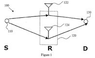
FIG. 1 is a schematic drawing of a communication channel having a source station S, relay station R and destination station D, according to an embodiment of the invention;
-
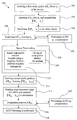
FIG. 2 is a flow diagram of a scheme for inserting cyclic prefixes according to a Cyclic Prefix Scheme 1 of the example embodiment;
-
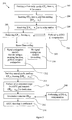
FIG. 3 is a flow diagram of a scheme for inserting cyclic prefixes according to a Cyclic Prefix Scheme 2 of the example embodiment;
-
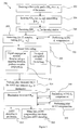
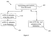
FIG. 4 is a flow diagram of a method for performing channel estimation according to the example embodiment;
DETAILED DESCRIPTION OF THE PREFERRED EMBODIMENTS
-
FIG. 1 shows a communication channel according to an example embodiment. This channel consists of a source station/node 110 (S), a relay station 120 (R) and a destination station/node 130 (D). The source and the destination each have only one antenna, and the relay station 120 has two antennae 122,124. The antennae at the source station/node 110, the relay station 120 and the destination station/node 130 can be configured to both transmit and receive. The source 110 sends signals to the relay station 120, and the relay station 120 sends signals to the destination 130. The signals sent from the source 110 to the relay station 120, and from the relay station 120 to the destination 130 may comprise multiple orthogonal carrier frequencies, such as in the case where OFDM modulation is used.
-
The present embodiment includes only one relay station 120. An ASTC relaying scheme is applied using orthogonal frequency division multiplexing (OFDM) modulation at the source 110. ASTC encoding is applied to individual carriers over two consecutive OFDM symbol periods. The relay station 120 receives the OFDM signal using the two antennae 122, 124. It does simple analog processing (such as the sampling and storage of discrete time signals) of the received signal and performs coding. This coding can for example be 2×2 Alamouti coding. The coded signal is then transmitted to the destination node/station 130.
-
To avoid interference, the data transmission from the source node/station 110 to destination node/station 130 takes place over two phases. The transmission cycle thus consists of two phases. In the first phase, the source node/station 110 to relay station 120 link is activated and the destination node/station 130 remains silent. In the second phase, the relay station 120 to destination node/station 130 link is activated and the source node/station 110 remains silent.
-
Simulations of the present embodiment were conducted using 16 carriers in each OFDM symbol. This however does not limit the number of carriers to 16 and a skilled reader will understand that the number of carriers can be varied.
-
Alternative embodiments may also apply the ASTC relaying schemes to single-carrier cyclic prefix (SC-CP) systems where the ASTC encoding is also applied to individual symbols over two consecutive SC-CP blocks.
-
Alternative embodiments may also have more than two antennae at the relay station 120, in which case antenna selection can be adopted. Only two antennas are selected to implement the proposed schemes based on pre-defined selection criteria, e.g., best product channel SNR, etc.
-
Alternative embodiments may also have multiple relay stations where relay selection can be performed in which one relay station is selected to implement the proposed schemes based on a pre-determined selection criteria, e.g., best product channel SNR, etc.
-
Alternative embodiments may also have multiple relay stations where Coordinated Delay ASTC is implemented at each relay station, and the coordinated delays are applied at different relay station. In this case, the delay durations applied at the different relay station is a design parameter obtained from a central control. This embodiment may have the advantage that the carrier frequencies do not have to be orthogonal and thus signal collisions will not occur.
-
Alternative embodiments may also have only one antenna at the relay station 120. In this case, a solution is to implement cooperation using at least two relay sub-stations, where each relay sub-station is a relay station capable of performing information passing with other relay sub-stations. Information passing is implemented between the at least two relay sub-stations and the at least two relay sub-stations can then participate in the ASTC transmission.
-
Angular Carrier Frequency Offset (ACFO)
-
Let the number of carriers be N. The source 110 to relay station 120 and relay station 120 to destination 130 channels are assumed to be frequency selective multipath fading channels. Let the vectors hS,1 and hS,2 respectively denote the channel impulse response (CIR) from the source 110 to the first and second antennae 122, 124 of the relay station 120. hS,1 and hS,2 both have the size of (L1×1). Similarly, let the vectors h1,D and h2,D respectively denote the CIR from the first and second antennae 122, 124 of the relay station 120 to the destination 130. h1,D and h2,D both have the size of (L2×1). Let f0, fr and fd be the carrier frequency of the local oscillators at the source 110, relay station 120 and destination 130, respectively. Then Δfr=f0−fr and Δfd=f0−fd respectively denote the CFO at the relay 120 and destination 130. The source 110, relay station 120 and destination 130 can have independent local oscillators and thus their oscillating frequency need not be the same. This results in independent CFOs in the signal received at relay station 120 and the destination 130 i.e. Δfr≠Δfd.
-
The angular CFO (ACFO) is defined as
-
-
where φr denotes the ACFO that is present at the channels between the source 110 and either antenna 122, 124 of the relay station 120, and φd denotes the ACFO that is present at the channels between either antenna 122, 124 of the relay station 120 and the destination 130. T denotes the OFDM symbol duration. Scalars εr=(Δfr)T and εd=(Δfd)T are referred to as normalized CFOs and their magnitudes are bounded by |εr|≦0.5 and |εd|≦0.5.
-
The ACFO φr and/or φd can be estimated during channel estimation and are used to perform compensation either at the relay station 120, or at the destination 130.
-
Joint ACFO compensation can also be performed at the destination 130, in which case no ACFO compensation needs to be done at the relay station 120. What this means is that compensation for (φr+φd) is done at the destination 130.
-
If the CFOs present in the signal received at the relay station 120 and destination 130 are not properly compensated, then the gains due to the relaying and usage of OFDM modulation cannot be realized.
-
Joint ACFO compensation when done at the destination 130 is advantageous as it keeps the relay carrier frequency unaffected for any source-and-destination pair.
-
Joint ACFO compensation when done at the destination 130 is also advantageous as it simplifies the implementation of the relay station 120 and reduces the computational complexity at the relay station 120.
-
Cyclic Prefix Schemes with Carrier Frequency Offset (CFO) Compensation
-
The embodiment employs two cyclic prefix schemes which are described below with their associated methods of performing carrier frequency offset (CFO) compensation. The Cyclic Prefix Schemes 1 and 2 of the present invention permits the implementation of space-time codes with minimum signal processing complexity at the relay station.
-
It is understood that the term “CP Scheme 1” is also used in this document to refer to the Cyclic Prefix Scheme 1 and “CP Scheme 2” is also used to refer to the Cyclic Prefix Scheme 2.
-
Cyclic Prefix Scheme 1
-
FIG. 2 shows a scheme for inserting cyclic prefixes according to the example embodiment. Let xj be a (N×1) vector containing the N data symbols to be transmitted during a j-th OFDM symbol duration.
-
While this example embodiment of the invention has been described using 2 OFDM symbols i.e. x2n, and x2n+1, it is clear that the use of a different number of OFDM symbols is possible within the scope of the invention, as will be clear to a skilled reader.
-
In step 202, the source derives a first cyclic prefix (denoted CPj,1) with length P1=L1−1 from xj. L1 is the length of the channel impulse response (CIR) represented by hS,1 and hS,2 respectively for the channel between the source and the first antenna of the relay station, and the channel between the source and the second antenna of the relay station.
-
In step 204, the source inserts CPj,1 in front of xj and then transmits the resultant symbol sequence.
-
Let the symbol sequence xj consisting of N symbols be denoted by xn where n=0 . . . N−1, i.e.
-
xj=[x0 . . . xn . . . xN-1]
-
The cyclic prefix CPj,1 of length P1 is created by copying the last P1 symbols of xj
-
CPj,1=└xN-P 1 . . . xN-2 . . . xN-1┘
-
The cyclic prefix CPj,1 is inserted in front of xj, producing the resultant symbol sequence └CPj,1 xj┘ for transmission.
-
The transmission from the source to relay station takes place in the first phase of the transmission cycle.
-
In step 206, the relay station receives └CPj,1 xj┘ at both antennae of the station.
-
In step 208, after performing time synchronization, the CPj,1 portion of length P1 in each OFDM symbol is removed leaving xj. Should ACFO be present, the signal vectors received over the span of 2 OFDM symbol durations i.e. for j={2n, 2n+1} are given after the removal of CPj,1 as
-
-
rR,i,j denotes the received signal vector obtained after the removal of CPj,1, with i and j respectively denoting the antenna index and OFDM symbol duration. rR,i,j has the size of (N×1). n denotes the data transmission cycle index. The (N×N) matrix WN H is the inverse discrete Fourier transform (IDFT) matrix. The first column vector of the (N×N) circulant matrices hS,1 and HS,2 are [hS,1 T, 01×(N-L)]T and [hS,2 T, 01×(N-L)]T, respectively.
-
Vector vR,i,j contains N samples of additive white Gaussian noise (AWGN) that distorts the signal received by the i-th relay antenna during j-th OFDM symbol duration. If 2d OFDM symbols are transmitted in each cycle with d being an integer value, then the matrix
-
-
will be of dimension (2N×2d) with OFDM symbol indexes of 2dn, 2dn+1, 2dn+2, . . . , 2dn+2d−1.
-
It is assumed that the covariance of vR,i,j,
-
E[v R,i,j v R,i,j H]=σR 2 I N for i=1,2 and j=2n,2n+1 for d>1.
-
Optionally, in the event that ACFO is present, compensation of ACFO φr can be performed at the relay station as step 230.
-
Assuming the complete removal of ACFO or if ACFO was absent, over the span of 2 OFDM symbol durations i.e. for j={2n, 2n+1}, the received signal vectors obtained after the removal of CPj,1 at the relay are given as follows:
-
-
Step 209 is then performed at the relay station. In step 209, Simple processing is performed in order to implement space-time coding at the carrier level. The matrix YR is computed and arranged:
-
-
The space-time code implemented can for example be the Alamouti code.
-
Given that
-
H S,1 W N H x j =W N HΛS,1 x j for j=2n, 2n+1 and i=1, 2,
-
where ΛS,i is a (N×N) sized diagonal matrix whose diagonal elements are given by the N-point DFT of CIR hS,i for i=1, 2, i.e., ΛS,i=√{square root over (N)}diag (WN[hS,i T, 01×(N-L i )]T), it can be shown that
-
-
where the (2N×2N) sized matrix {tilde over (V)}R,n is given by
-
-
Step 209 further comprises steps 210 and 212.
-
In step 210, for those elements of YR where no signal conjugation is needed e.g.: for y11,R and y12,R, nothing needs to be done.
-
In step 212, for those elements of YR where signal conjugation is needed e.g.: for y21,R and y22,R, the OFDM symbol sequence is reordered using a mapping function ζ(.):
-
ζ(a)=[a(N−1), a(N−2), . . . ,a(0)]T,
-
the (N×1) sized input vector a=[a(0), a(1), . . . , a(N−1)]T. This function can be easily implemented in hardware by storing the signal samples in a shift register and then reading the register in reverse order. This represents a significant advantage because reordering operations that are more complex than mere reversal, such as the insertion, deletions and swapping of signal samples do not have to be done.
-
It can be shown that
-
-
where matrix ZN(φ) denotes a (N×N) diagonal matrix given by
-
Z N(φ)=diag([1,e jφ ,e j2φ , . . . ,e j(N-1)φ]T)
-
and T is a (N×N) permutation matrix such that
-
T=[ζ(I N)](1) and TT=I N.
-
IN is an identity matrix of size N. The operator [•]* represents a complex conjugation.
-
The notation [a](l) denotes the circular shifting of vector a by l elements, where
-
[a] (2) =[a(N−2),a(N−1),a(0),a(1), . . . ,a(N−3)]T.
-
For a given matrix X, matrix [X](l) is obtained by circular shifting each column vector of X by l elements.
-
In step 213, a second cyclic prefix (denoted CPij,2) with length P2 where P2=L2−1 is obtained for each yij,R. L2 is the length of the CIRs denoted by the vectors h1,D and h2,D respectively for the channel between the first antenna of the relay station and the destination, and the channel between the second antenna of the relay station and the destination. Each of the cyclic prefixes CPij,2 is derived from the corresponding yij,R.
-
The cyclic prefixes CPij,2 are then inserted in front of yij,R to produce the symbol sequences └CPij,2 yij,R ┘. It is to be noted that yij,R is a (N×1) sized vector.
-
In step 214, the other necessary steps for the ASTC implementation at the relay station are performed. The symbol sequences └CPij,2 yij,R ┘ are then transmitted by the i-th relay antenna during the j-th OFDM symbol duration, where i=1, 2 and j={2n, 2n+1}. The transmission from the relay station to destination takes place in the second phase of the transmission cycle where the source remains silent.
-
In step 216, after frame synchronization, the destination removes the cyclic prefix of length P2 from each OFDM symbol received. The OFDM symbol with the cyclic prefix removed can be denoted by the (N×1) signal vector rD,j for each j-th OFDM symbol duration.
-
Assuming that ACFO is present and ACFO compensation was done at the relay, for the j={2n, 2n+1}-th OFDM symbol duration, the (N×1) received signal vectors at the destination in the presence of ACFO φd are given by
-
-
where the noise vectors are given by
-
-
Optionally, ACFO φd compensation can be performed at the destination as step 240.
-
Assuming that ACFO is present and no ACFO compensation was done at the relay, for the j={2n, 2n+1}-th OFDM symbol duration,
-
-
H1,D and H2,D are (N×N) circulant matrices respectively with [h1,D T, 01×(N-L)]T and [h2,D T, 01×(N-L)]T as their first column vectors. The (N×1) vector PD,2n represent additive noise.
-
Assuming that ACFO compensation was performed, or if ACFO is absent, for the j=(2n)-th OFDM symbol duration
-
-
The (N×1) vector pD,2n representing the additive noise is given by
-
P D,2n =H 1,D v R,1,2n +H 2,Dζ(v* R,2,2n+1)+V D,2n,
-
where the (N×1) vector VD,2n contains the N samples of AWGN at destination with covariance matrix E[vD,2nvD,2n H]=σD 2IN.
-
Similarly, for the j=(2n+1)-th OFDM symbol duration,
-
-
In step 218, the destination performs ASTC decoding in the frequency domain using the channel state information (CSI) parameters that were obtained during training. N-point DFTs are performed on the signal vector rD,j for the symbol durations j={2n, 2n+1}. Assuming that ACFO is absent, the N-point DFT of rD,2n is
-
-
Similarly, the N-point DFT of the signal vector received by the destination during the (2n+1)-th OFDM symbol duration (i.e. rD,2n+1) is given by
-
-
A (2N×1) vector yD,n is constructed as
-
-
Estimates of x2n and x2n+1 (denoted {tilde over (x)}2n {tilde over (x)}2n+1) can be obtained using the conjugate transpose of HP i.e. HP H
-
-
HP is the (2N×2N) sized product channel matrix and is given by
-
-
The product channel matrix HP is a known parameter obtained during the product channel matrix estimation and forms part of the channel state information (CSI). HP allows for a simple linear decoding at destination, since
-
H P H H P =I 2 (|Λ
1,D|
2|Λ
S,1 2|+|Λ
2,D|
2|Λ
S,2|
2)
-
where
denotes performing a Kronecker product.
-
In step 230, the relay station optionally performs ACFO φr compensation. The signal vectors rR,i,j received over the span of 2 OFDM symbol durations j={2n, 2n+1} for antennae i=1, 2 are:
-
-
The ACFO φr is a known parameter obtained at the relay station during the ACFO {circumflex over (φ)}r, estimation step 410 and forms part of the channel state information (CSI).
-
The effect of the ACFO φr can be removed for rR,1,2n and rR,2,2n by multiplying rR,1,2n and rR,2,2n with the conjugate of ej(2n(N+P 1 )+P 1 )φ r ZN(φr). The effect of the ACFO φr can be removed for rR,1,2n+1 and rR,2,2n+1 by multiplying rR,1,2n+1 and rR,2,2n+1 with the conjugate of ej((2n(N+P 1 )+P 1 )φ r ZN(φr).
-
In step 240, the destination optionally performs ACFO φd compensation. The (N×1) received signal vectors at the destination in the presence of ACFO φd are given by
-
-
where the noise vectors are given bypD,2n and pD,2n+1. The ACFO φd is a known parameter obtained at the destination during the ACFO {circumflex over (φ)}d — estimation step 420 and forms part of the channel state information (CSI).
-
The effect of the ACFO φd can be removed by multiplying rD,2n and rD,2n+1 respectively with the conjugate of ej(2n(N+P 2 )+P 2 )φ d ZN(φd) and ej((2n+1)(N+P 2 )+P 2 )φ d ZN(φd).
-
The Cyclic Prefix Scheme 1 may have the advantage that only analog domain processing has to be done at the relay, and only linear processing has to be done for maximum likelihood decoding at the destination.
-
Cyclic Prefix Scheme 2
-
FIG. 3 shows an alternative scheme for inserting cyclic prefixes according to the example embodiment. Let xj be a (N×1) vector containing the N data symbols to be transmitted during a j-th OFDM symbol duration.
-
While this example embodiment of the invention has been described using 2 OFDM symbols i.e. x2n and x2n+1, it is clear that the use of a different number of OFDM symbols is possible within the scope of the invention, as will be clear to a skilled reader.
-
In step 302, the source derives a first cyclic prefix (denoted CPj,1) with length P from xj, where P=P1+P2=L1+L2−2. L1 is the length of the channel impulse response (CIR) represented by hS,1 and hS,2 respectively for the channel between the source 110 and the first antenna 122 of the relay station 120, and the channel between the source 110 and the second antenna 124 of the relay station 120. L2 is the length of the CIRs denoted by the vectors h1,D and h2,D respectively for the channel between the first antenna 122 of the relay station 120 and the destination 130, and the channel between the second antenna 124 of the relay station 120 and the destination 130.
-
In step 304, the source inserts CPj,1 in front of xj and then transmits the resultant symbol sequence.
-
Let the symbol sequence xj consist of N symbols be denoted by xn where n=0 . . . N−1, i.e.
-
xj=[x0 . . . xn . . . xN−1]
-
The cyclic prefix CPj,1 of length P1 is created by copying the last Ncp words of xj
-
CPj,1=└xN-P 1 . . . xN-2 . . . xN-1┘
-
The cyclic prefix CPj,1 is inserted in front of xj, producing the resultant symbol sequence └CPj,1 xj ┘ for transmission.
-
The transmission from the source 110 to relay station 120 takes place in the first phase of the transmission cycle.
-
In step 306; the relay station receives └CPj,1 xj┘ at both antennae of the station.
-
In step 308, after performing time synchronization, the first P1 samples of the CPj,1 portion of each OFDM symbol is removed, leaving a sequence represented by └CPj,2 xj ┘. The first P1 samples of each OFDM symbol are distorted by the ISI induced by the frequency selective fading occurring at the source to relay channels. The resulting OFDM symbol will then have (N+P2) samples. Should ACFO be present, the signal vectors received over the span of 2 OFDM symbol durations i.e. for j={2n, 2n+1} are given after the removal of CPj,1 as
-
-
{tilde over (r)}R,i,j denotes the ((N+P2)×1) received signal vector obtained after the removal of P1 samples, with i and j respectively denoting the antenna index and OFDM symbol duration. n denotes the data transmission cycle index. The (N×N) matrix WN H is the inverse discrete Fourier transform (IDFT) matrix. Matrix {tilde over (H)}S,1 for i=1, 2 is a ((N+P2)×N) matrix given by
-
-
with HS,1 being a (N×N) circulant matrix with [hS,1 T, 01×(N-L 1 )]T as its first column vector and HS,1(N−P2+1: N,:) denotes the last P2 row vectors of HS,1.
-
The vector {tilde over (v)}R,i,j of size ((N+P2)×1) contains the AWGN affecting the signal {tilde over (r)}R,i,j. The covariance matrix of the noise vector {tilde over (v)}R,i,j at the relay station is given by
-
E{{tilde over (v)}R,i,j{tilde over (v)}R,i,j H}=σR 2IN+P 2
-
Optionally, in the event that ACFO is present, ACFO φr compensation can be performed at the relay station as Step 330.
-
Assuming the complete removal of ACFO or if ACFO was absent, over the span of 2 OFDM symbol durations i.e. for j={2n, 2n+1}, the received signal vectors obtained after the removal of the first P1 samples of the CPj,1 portion of each OFDM symbol are given as follows:
-
-
Step 309 is then performed at the relay station. In step 309, processing is performed in order to implement space-time coding at the carrier level. The matrix YR is computed and arranged:
-
-
The operator [•]* represents a complex conjugation. The space-time code implemented can for example be the Alamouti code.
-
Step 309 further comprises steps 310 and 312.
-
In step 310, for those elements of YR where no signal conjugation is needed e.g.: for y11,R and y12,R, nothing needs to be done.
-
In step 312, for those elements of YR where signal conjugation is needed e.g.: for y21,R and y22,R, the OFDM symbol sequence from the respective {tilde over (r)}R,i,j is reordered using the mapping function ζ(.):
-
ζ(a)=[a(N−1),a(N−2), . . . ,a(0)]T,
-
the (N×1) input vector a=[a(0), a(1), . . . , a(N−1)]T. This function can be easily implemented in hardware by storing the signal samples in a shift register and then reading the register in reverse order.
-
The mapping function ζ(.) can thus be re-expressed as
-
ζ(a(n))=a(N−n−1)
-
where a(n) denotes the n-th symbol of the OFDM symbol sequence a. A time domain signal conjugation is then performed on each reordered symbol ζ(a(n)), for n=0 . . . N−1.
-
Let b=ζ(a). It can be shown that after signal conjugation is done, taking B={B(0) . . . B(k) . . . B(N−1)} to be the corresponding frequency domain sequence of b
-
B*(k)W N k(N-P 2 −1) =B*(k)W N −k(P 2 +1)
-
i.e., the phase-shifted conjugate sequence.
-
The following Discrete Fourier Transform (DFT) properties are present:
-
- Linearity: ax(n)+by(n)+by(n)aX(k)+bY(k);
- Cyclic Shift x((n+m)N)WN −kmX(k);
- Symmetry x*((−n)N)X*(k)
x(n) and y(n) to denote the time domain sequence, X(k) and Y(k) their corresponding frequency domain sequence, N the DFT size, and
-
-
In step 314, the other necessary steps for the ASTC implementation at the relay station are performed. The symbol sequences contained in
-
-
are then transmitted by the i-th relay antenna during the j-th OFDM symbol duration, where i=1,2 and j={2n, 2n+1}. The transmission from the relay station to destination takes place in the second phase of the transmission cycle where the source remains silent.
-
In step 316, after frame synchronization, the destination removes the cyclic prefix of length P2 from each OFDM symbol received. Each OFDM symbol after cyclic prefix removal will be N samples long and can be denoted by the signal vector rD,j for each j-th OFDM symbol duration.
-
Assuming that ACFO is present and ACFO compensation was done at the relay, for the j={2n, 2n+1}-th OFDM symbol duration, the (N×1) received signal vectors at the destination in the presence of ACFO φd are given by
-
-
where the noise vectors are given by
-
-
Optionally, ACFO φd compensation can be performed at the destination as step 340.
-
Assuming that ACFO is present and no ACFO compensation was done at the relay, for the j={2n, 2n+1}-th OFDM symbol duration,
-
r D,2n =e j(2n(N+P 2 )+P 2 )(φ d +φ r ) Z N(φd+φr)[αn {hacek over (H)} 1,D H S,1 W N H x 2nγn {hacek over (H)} 2,D G S,2(W N H x 2n+)*]+{tilde over (p)} D,2n
-
r D,2n+1 =e j((2n+1)(N+P 2 )+P 2 )(φ d +φ r ) Z N(φd+φr)[αn e jP 1 φ r {hacek over (H)} 1,D H S,1 W N H x 2n+1−γn e jP 1 φ r {hacek over (H)} 2,D G S,2(W N H x 2n)*]+{tilde over (p)} D,2n+1,
-
where {hacek over (H)}1,D and {hacek over (H)}2,D are (N×N) circulant matrix with ZN(−φr) [h1,D T, 01×(N-L 2) ]T and Z N(−φr) [h2,D T, 01×(N-L 2) ]T as their respective first column vectors and scalars αn and γn are defined as follows:
-
αn=ej(2n+1)P 1 φ r
-
γn=e−j((4n+2)(N+P)−2nP 1 -1)φ r.
-
Optionally, joint ACFO compensation can be performed at the destination as step 350 to compensate for the ACFO φr and φd.
-
Assuming that ACFO compensation was performed, or if ACFO is absent, for the j=(2n)-th OFDM symbol duration
-
r D,2n =H 1,D H S,1 W N H x 2n +H 2,D G S,2(W N H x 2n+1)*+{tilde over (p)} D,2n,
-
The (N×N) matrix GS,2 is given by
-
G S,2=ζ({tilde over (H)}* S,2(1:N,:)).
-
The mapping ζ(.) for a 2-dimensional matrix A is computed as follows:
-
Given that A has a size of (N1×N2) and A=[a1, a2, . . . , aN 2 ] where ai is (N1×1) vector for i=1, 2, . . . , N2, then ζ(A)=[ζ(a1), ζ(a2), . . . , ζ(aN 2 )].
-
The (N×1) vector {tilde over (p)}D,2n is given by
-
{tilde over (p)} D,2n =R cp [U 1,D {tilde over (v)} R,1,2n +U 2,Dζ({tilde over (v)} R,2,2n+1)]v D,2n,
-
where vector vD,2n contains the AWGN received at the destination for i=1, 2, the matrix U1,D is a ((N+P2)×(N+P2)) Toeplitz matrix with [h1,D T, 01×(N+P 2 −L 2 )]T as its first column vector and [h1,D(1, 1), 01×(N+P 2 −1)] as its first row vector. Matrix Rcp is a (N×(N+P2)) matrix defined as
-
Rcp=[0N×P 2 ,IN].
-
Similarly, the (N×1) sized signal vector received at the destination during (2n+1)th OFDM symbol duration is obtained to be
-
r D,2n+1 =H 1,D H S,1 W N H x 2n+1 −H 2,D G S,2(W N H x 2n)*+{tilde over (p)} D,2n+1,
-
{tilde over (p)} D,2n+1 =R cp [U 1,D {tilde over (v)}R,1,2n+1 U2,Dζ({tilde over (v)}* R,2,2n)]+v D,2n+.
-
In step 318, the destination performs the ASTC decoding in the frequency domain using the channel state information (CSI) parameters that were obtained during training. N-point DFTs are performed on the signal vector rD,j for the symbol durations j={2n, 2n+1}, resulting in the vectors WNrD,2n and WNrD,2n+1
-
A (2N×1) vector yD,n is constructed as
-
-
The signals rD,2n and rD,2n+1 can be represented as
-
r D,2n =H 1,D H S,1 W N H x 2n +H 2,D G S,2(W N H x 2n+1)*+{tilde over (p)} D,2n,
-
r D,2n+1 =H 1,D H S,1 W N H x 2n+1 −H 2,D G S,2(W N H x 2n)*{tilde over (p)} D,2n+1,
-
The matrix GS,2 is defined to be a (N×N) matrix of the form:
-
G S,2=ζ({tilde over (H)}* S,2(1:N,:)).
-
It can be observed that matrix GS,2 can be obtained by permutating the column vectors of a (N×N) circulant matrix CS,2=WN HΛ* S,2WN. Using this knowledge, it can be shown that
-
-
Substituting GS,2 in the (N×1)-sized vector H2,DGS,2(WN Hx2n+1)*,
-
-
Similarly, the (N×1) vector H2,DGS,2(WN Hx2n)* can be expressed as
-
-
Substituting the expressions of H2,DGS,2(WN Hx2n+1)* and H2,DGS,2(WN Hx2n)* into yD,n,
-
-
Estimates of x2n and x2n+1 (denoted {tilde over (x)}2n and {tilde over (x)}*2n+1) can be obtained using the conjugate transpose of HP i.e. HP H
-
-
HP is the (2N×2N) sized product channel matrix and is given by
-
-
The product channel matrix HP is a known parameter obtained during the product channel matrix estimation and forms part of the channel state information (CSI). HP allows for a simple linear decoding at destination, since
-
H P H H P =I 2 (|Λ
1,D|
2|Λ
S,1|
2|Λ
2,D|
2|Λ
S,2|
2).
-
where
denotes performing a Kronecker product.
-
It can be seen that the present embodiment has an advantage in that there is no need for any sample reordering to be done at the destination.
-
In the event that ACFO is present and joint ACFO compensation was done in step 316, the ASTC decoding in the frequency domain can be performed using step 320 instead of step 318.
-
In step 320, the (2N×1) vector yD,n will be
-
-
The scalars αn and γn are defined as:
-
αn=ej(2n+1)P 1 φ r
-
γn=e−j((4n+2)(N+P)−2nP 1 −1)φ r.
-
where φr represents the ACFO φr. The value of φr can be estimated at the relay using the ACFO {circumflex over (φ)}r estimation step 410 and then forwarded to the destination.
-
Estimates of x2n and x2n+1 (denoted {tilde over (x)}2n and {tilde over (x)}*2n+1) can thus be obtained using {tilde over (H)}F such that
-
-
{tilde over (H)}F H represents the conjugate transpose of {tilde over (H)}F. {tilde over (H)}F has the property that
-
{tilde over (H)} F H {tilde over (H)} F =I 2 (|{hacek over (Λ)}
1,D|
2|Λ
S,1|
2+|{hacek over (Λ)}
2,D|
2|Λ
S,2|
2).
-
where
denotes performing a Kronecker product. {tilde over (H)}
F thus allows for a simple linear decoding at the destination.
-
In step 330, the relay station optionally performs ACFO φr compensation. The signal vectors {tilde over (r)}R,i,j received over the span of 2 OFDM symbol durations j={2n,2n+1} for antennae i=1, 2 are:
-
-
The ACFO φr is a known parameter obtained at the relay station during the ACFO {circumflex over (φ)}r estimation step 410 and forms part of the channel state information (CSI).
-
The effect of the ACFO φr can be removed for {tilde over (r)}R,1,2n and {tilde over (r)}R,2,2n by multiplying with the conjugate of ej(2n(N+P 1 )+P 1 )φ r ZN(φr). The effect of the ACFO φr can be removed for {tilde over (r)}R,1,2n+1 and {tilde over (r)}R,2,2n+1 by multiplying with the conjugate of ej((2n+1)(N+P 1 )+P 1 )φ r ZN(φr).
-
In step 340, the destination optionally performs ACFO φd compensation. The (N×1) received signal vectors at the destination in the presence of ACFO φd are given by
-
-
where the noise vectors are given by {tilde over (p)}D,2n and {tilde over (p)}D,2n+1. The ACFO φd is a known parameter obtained during the ACFO {circumflex over (φ)}d estimation step 420 and forms part of the channel state information (CSI).
-
The effect of the ACFO φd can be removed by multiplying rD,2n and rD,2n+1 respectively with the conjugate of ej(2n(N+P 2 )+P 2 )φ d ZN(φd) and ej((2n+1)(N+P 2 )+P 2 )φ d ZN(φd).
-
In step 350, the destination optionally performs joint ACFO compensation. The (N×1) signal vectors received at the destination for the j={2n, 2n+1}-th OFDM symbol duration are given by
-
r D,2n =e j(2n(N+P 2 )+P 2 )(φ d +φ r ) Z N(φd+φr)[αn {hacek over (H)} 1,D H S,1 W N H x 2n+γn {hacek over (H)} 2,D G S,2(W N H x 2n+1)*]
-
r D,2n+1 =e j((2n+1)(N+P 2 )+P 2 )(φ d +φ r ) Z N(φd+φr)[αn e jP 1 φ r {hacek over (H)} 1,D H S,1 W N H x 2n+1−γn e jP 1 φ r {hacek over (H)} 2,D G S,2(W N H x 2n)*]+{tilde over (p)} D,2n+1,
-
where the noise vectors are given by {tilde over (p)}D,2n and {tilde over (p)}D,2n+1.
-
The scalars αn and γn are defined as follows:
-
αn=ej(2n+1)P 1 φ r
-
γn=e−j((4n+2)(N+P)−2nP 1 -1)φ r.
-
It can be seen that ACFO φr and ACFO φd are present in the signal vectors rD,2n and rD,2n+1. ACFO φr and ACFO φd can be added together and be represented by ACFO φf i.e. φf=φd+φr. The ACFO φf is a known parameter obtained during the joint ACFO (φr+φd) estimation step 430 and forms part of the channel state information (CSI).
-
The effect of the ACFO φf can be removed by multiplying rD,2n and rD,2n+1 respectively with the conjugates of ej(2n(N+P 2 )+P 2 )(φ d +φ r )ZN(φd+φr) and ej((2n+1)(N+P 2 )+P 2 )(φ d +φ r )ZN(φd+φr).
-
The Cyclic Prefix Scheme 2 may have the advantage that only analog domain processing has to be done at the relay, and only linear processing has to be done for maximum likelihood decoding at the destination for each carrier.
-
The Cyclic Prefix Scheme 2 may also be advantageous over the prior art because the relay station does not have to perform time sharing between different sources and destinations. In the prior art, the relay station will need to estimate and compensate the ACFO for each source-and-destination pair as joint ACFO compensation at the destination is not done. This can complicate the relay station hardware and could increase the computational complexity required at the relay station.
-
Channel Estimation
-
Channel estimation is performed before actual information is transmitted according to the method shown in the flow-chart of FIG. 2 or FIG. 3. The purpose of channel estimation is to obtain a set of Channel State Information (CSI) parameters for use in decoding the signals received at the destination and optionally to compensate for Angular Carrier Frequency Offset (ACFO) at either the relay station or the destination.
-
Channel estimation according to the example embodiment will be described next with reference to FIG. 4.
-
In step 402, a simple pair of pilot symbols (or training symbols) is used to estimate the product channel. The pair of pilot symbols comprising of
-
[x2nx2n+1]
-
is transmitted over two symbol intervals from the source. The pilot symbols are defined as
-
x2n=a
-
X
2n+1
=−a
-
where a is a (N×1) vector such that |a(i)|=1 for i=0, 1, . . . , N−1 and a has low peak to average power ratio (PAPR). n denotes the data transmission cycle index.
-
ACFO {circumflex over (φ)}r Estimation at the Relay Station
-
In step 410, ACFO {circumflex over (φ)}r estimation is performed at the relay station for either of Cyclic Prefix Schemes 1 or 2. Given the known values of the pilot symbols [x2n x2n+1], the ACFO at the relay {circumflex over (φ)}r can be easily estimated as
-
-
The operator ∠(.) returns the phase of (.) and hence the returned scalar is within the interval [−π,π). It is to be noted that
-
-
and hence the maximum normalized CFO that can be estimated is given by the bounds
-
-
The above limitation can be overcome by designing suitable pilot symbols. The estimated ACFO value {circumflex over (φ)}r can be used by the relay to do the compensation during the transmission of actual information.
-
Cyclic Prefix Scheme 2 may have the advantage that ACFO compensation at relay is not necessary because joint ACFO compensation can be performed at the destination.
-
ACFO {circumflex over (φ)}d Estimation at the Destination
-
In step 420, ACFO {circumflex over (φ)}d estimation is performed at the destination station for either of Cyclic Prefix Schemes 1 or 2.
-
For Cyclic Prefix Scheme 1, the (N×1) received signal vectors at the destination in the presence of ACFO φd are given by
-
-
where the noise vectors are given by
-
-
Similarly, the (N×1) received signal vectors at the destination for CP Scheme 2 are given by
-
-
where the noise vectors are given by
-
-
The following estimation applies for either of Cyclic Prefix Schemes 1 or 2. Using the pilot symbols of x2n=a and x2n=−a that were transmitted by the source, it is assumed that WN Ha=b. The (N×N) matrix WN H is the inverse discrete Fourier transform (IDFT) matrix. Therefore, vector H1,DHS,1WN Hx2n can be expressed as
-
-
where the (N×(P+1)) Toeplitz matrix A is given by
-
A=[[b ](0),[b](1), . . . ,[b](P)]
-
and the ((P+1)×1) vector hp is
-
h
P
=h
1,D
*h
S,1
-
with * denoting convolution operation. Let us assume that d=WN HTa*.
-
Vector H2,D ζ(H*S,2)d can be written as
-
H 2,Dζ(H* S,2)d=B{tilde over (h)} P,
-
where the (N×(P+1)) Toeplitz matrix B is given by
-
B=[[f](−L 1 +1),[f](−L 1 +2), . . . ,[f](−L 1 +P+1)]
-
with f=ζ(d) and the ((P+1)×1) vector {tilde over (h)}P is
-
{tilde over (h)} P =h 2,D*ζ(h* S,2).
-
Similarly, vector H2,DGS,2d can be expressed as
-
H2,DGS,2d=C{tilde over (h)}P,
-
where the (N×(P+1)) Toeplitz matrix C is given by
-
c=[[f](−2L 2 +1),[f](−2L 2 +2), . . . ,[f](−2L 2 +P+1)].
-
Substituting the above results into rD,2n and rD,2n+1 and bearing in mind that rD,2n and rD,2n+1 are the received signal vectors of the pilot symbols at the destination, rD,2n and rD,2n+1 can be rewritten as
-
-
-
where the (2(P+1)×1) vector hF
-
hF=[hP T, {tilde over (h)}P T]T.
-
Let qn be a (2N×1) vector constructed as
-
-
where en=[pD,2n T, pD,2n+1 T]T for CP Scheme 1 and en=[{tilde over (p)}D,2n T, {tilde over (p)}D,2n+1 T]T for CP Scheme 2. The (2N×2(P+1)) matrix F(φd) is given by
-
-
-
Using qn, a maximum likelihood (ML) based ACFO and CIR estimator can be formulated. The ACFO is estimated as
-
-
{circumflex over (φ)}d can be estimated using a grid search.
-
It is to be noted that, for the pilot symbols used in step 402, the matrix FH(φ)F(φ) is given by
-
F H(φ)F(φ)=NI 2(P+1).
-
This implies that the inverse of FH(φ)F(φ) need not be computed for every search point.
-
Hence the ACFO {circumflex over (φ)}d can be estimated as
-
-
It can be seen that the ACFO {circumflex over (φ)}d estimation at the destination is not computationally demanding as no inverse matrix computation needs to be done for each search point.
-
Once the ACFO {circumflex over (φ)}d is estimated, vector hF can be estimated as
-
-
Joint ACFO (φr+φd) Estimation at the Destination
-
In step 430, joint ACFO (φr+φd) estimation is performed at the destination for the Cyclic Prefix Scheme 2. The (N×1) received signal vectors at destination (without ACFO compensation at relay) can be written as follows:
-
r D,2n =e j(2n(N+P 2 )+P 2 )(φ d +φ r ) Z n(φd+φr)[αn {hacek over (H)} 1,D H S,1 W N H x 2n+γn {hacek over (H)} 2,D G S,2(W N H x 2n+1)*]
-
r D,2n+1 =e j((2n+1)(N+P 2 )+P 2 )(φ d +φ r ) Z N(φd+φr)[αn e jP 1 φ r {hacek over (H)} 1,D H S,1 W N H x 2n+1−γn e jP 1 φ r {hacek over (H)} 2,D G S,2(W N H x 2n)*]{tilde over (p)} D,2n+1,
-
where {hacek over (H)}1,D and {hacek over (H)}2,D respectively are (N×N) circulant matrix with ZN(−φr)[h1,D T,01×(N-L 2 )]T and ZN(−φr)[h2,D T, 01×(N-L 2 )] T as their first column vectors, and scalars αn and γn are defined as follows:
-
αn=ej(2n+1)P 1 φ r
-
γn=ej((4n+2)(N+P)−2nP 1 −1)φ r.
-
It is defined that φf=φd+φr. We have
-
-
where the (2N×2(P+1)) matrix {tilde over (F)}(φf, φr) is given by
-
-
and {tilde over (h)}F is a (2(P+1)×1) vector constructed as
-
{tilde over (h)} F=[({hacek over (h)} 1,D *h S,1)T,({hacek over (h)} 2,D*ζ(h* S,2))T]T
-
with {hacek over (h)}1,D=ZL 2 (−φr)h1,D and {hacek over (h)}2,D=ZL 2 (−φr)h2,D. It can be shown that
-
{tilde over (F)} H(φf,φr) {tilde over (F)}(φ f,φr)=NI 2(P+1).
-
The Maximum Likelihood estimate for φf is obtained as
-
-
and {tilde over (h)}F is estimated as
-
-
While example embodiments of the invention have been described in detail, many variations are possible within the scope of the invention as will be clear to a skilled reader. Variations can be made, for example to parameters such as the number of carriers, the cyclic prefix lengths P, P1 and P2, the coding technique used at the relay station, or the way in which the product channel is estimated. Variations can also be made to the design of the pilot symbols used. Further, the CP schemes need not necessary use space-time coding and other forms of coding may be used.