US20080098683A1 - Decorative wall covering with improved interlock system - Google Patents
Decorative wall covering with improved interlock system Download PDFInfo
- Publication number
- US20080098683A1 US20080098683A1 US11/588,540 US58854006A US2008098683A1 US 20080098683 A1 US20080098683 A1 US 20080098683A1 US 58854006 A US58854006 A US 58854006A US 2008098683 A1 US2008098683 A1 US 2008098683A1
- Authority
- US
- United States
- Prior art keywords
- panel
- marginal edge
- panels
- edge region
- wall covering
- Prior art date
- Legal status (The legal status is an assumption and is not a legal conclusion. Google has not performed a legal analysis and makes no representation as to the accuracy of the status listed.)
- Granted
Links
Images

Classifications
-
- E—FIXED CONSTRUCTIONS
- E04—BUILDING
- E04F—FINISHING WORK ON BUILDINGS, e.g. STAIRS, FLOORS
- E04F13/00—Coverings or linings, e.g. for walls or ceilings
- E04F13/07—Coverings or linings, e.g. for walls or ceilings composed of covering or lining elements; Sub-structures therefor; Fastening means therefor
- E04F13/08—Coverings or linings, e.g. for walls or ceilings composed of covering or lining elements; Sub-structures therefor; Fastening means therefor composed of a plurality of similar covering or lining elements
- E04F13/0801—Separate fastening elements
- E04F13/0832—Separate fastening elements without load-supporting elongated furring elements between wall and covering elements
- E04F13/0858—Separate fastening elements without load-supporting elongated furring elements between wall and covering elements fixed by means of spring action
-
- E—FIXED CONSTRUCTIONS
- E04—BUILDING
- E04D—ROOF COVERINGS; SKY-LIGHTS; GUTTERS; ROOF-WORKING TOOLS
- E04D1/00—Roof covering by making use of tiles, slates, shingles, or other small roofing elements
- E04D1/26—Strip-shaped roofing elements simulating a repetitive pattern, e.g. appearing as a row of shingles
- E04D1/265—Strip-shaped roofing elements simulating a repetitive pattern, e.g. appearing as a row of shingles the roofing elements being rigid, e.g. made of metal, wood or concrete
-
- E—FIXED CONSTRUCTIONS
- E04—BUILDING
- E04D—ROOF COVERINGS; SKY-LIGHTS; GUTTERS; ROOF-WORKING TOOLS
- E04D1/00—Roof covering by making use of tiles, slates, shingles, or other small roofing elements
- E04D1/29—Means for connecting or fastening adjacent roofing elements
- E04D1/2907—Means for connecting or fastening adjacent roofing elements by interfitted sections
- E04D1/2914—Means for connecting or fastening adjacent roofing elements by interfitted sections having fastening means or anchors at juncture of adjacent roofing elements
- E04D1/2918—Means for connecting or fastening adjacent roofing elements by interfitted sections having fastening means or anchors at juncture of adjacent roofing elements the fastening means taking hold directly on adjacent elements of succeeding rows
-
- E—FIXED CONSTRUCTIONS
- E04—BUILDING
- E04D—ROOF COVERINGS; SKY-LIGHTS; GUTTERS; ROOF-WORKING TOOLS
- E04D1/00—Roof covering by making use of tiles, slates, shingles, or other small roofing elements
- E04D1/29—Means for connecting or fastening adjacent roofing elements
- E04D1/2907—Means for connecting or fastening adjacent roofing elements by interfitted sections
- E04D1/2921—Means for connecting or fastening adjacent roofing elements by interfitted sections having resilient detents adapted to be biased to a position to resist separation
Definitions
- the present invention relates generally to roof and wall coverings which are primarily intended for outdoor usage, and more particularly, to roof and wall coverings comprised of relatively large panels which each are molded or otherwise formed with decorative patterns characteristic of conventional roofing and siding materials, such as shake shingles, tile, brick or the like.
- Various synthetic roof and wall coverings are known, such as those formed of elongated thermoplastic panels that are nailed or screwed to a wall or roof support surface in horizontal courses or rows in partially overlapping relation to each other so as to provide a substantially water resistant, protective layer over the support surface.
- Such panels which usually are identically molded, are commonly formed with a plurality of rows of simulated building elements, such as shake shingles. Because the panels are relatively large, such as up to eight feet and more in length, they can be cumbersome to handle and install, particularly on vertical wall and steep roof surfaces. Since the panels are identically molded, a panel-to-panel identity also can be easily noticed if the panels are not carefully installed. Leakage problems between adjoining panels can also occur under these circumstances.
- Such panels commonly are nailed to the wall or support surface in horizontal courses, beginning with the lower-most course.
- To enable interlocking engagement between the upper and lower marginal edge regions of vertically-adjacent panels it is known to provide a plurality of longitudinally-spaced outwardly and downwardly directed interlocked fingers along the upper marginal edge region of the underlying panel which are engaged by a bottom rail formed on the underside of the overlying panel as an incident to upward positioning movement of the panel. Due to the size of the panels it can be difficult for the installer to engage all of the fingers with the upturned rail, with any missed fingers causing an unsightly bowing of the overlying panel, which both detracts from its appearance of the finished wall covering and makes it more susceptible to water entering the juncture between the panels.
- the upturned interlock rail on the overlying panel extends across a rear side of the simulated shake, even with careful molding, a transverse line of the rail can sometimes be faintly observed from a front side of the panel, which again detracts from the natural appearance of the wall covering.
- the upturned rail also can undesirably capture and retain water that might migrate between the panels, such as during severe weather conditions.
- Another object is to provide a wall or roof panel as characterized above that facilitates proper positioning of a panel into overlying relation to a previously-installed panel.
- a further object is to provide a panel of the above kind which effects positive interlocking engagement of an overlying panel onto a previously-mounted panel sufficient to support the weight of the panel during securement onto the wall surface.
- a related object is to provide such a panel interlock arrangement that is releasable to permit adjustable positioning of the panel during installation if necessary, and to accommodate expansion and contraction of the panels from temperature changes during usage.
- Yet another object is to provide a wall or roof panel of the foregoing type which has an upturned interlock rail integrally molded on a rear side of the panel that does not detract from the exterior appearance of the simulated building elements.
- a further object is to provide such a wall panel in which the upturned interlock rail across the rear of the panel facilitates water drainage and air circulation through the completed wall covering.
- Still another object is to provide a wall or roof panel of such type which is relatively simple in construction and which lends itself to economical molding.
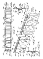
- FIG. 1 is a plan view of a wall covering comprising panels constructed in accordance with the present invention
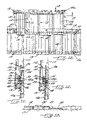
- FIG. 2 is a front plan view of one of the panels of the wall covering shown in FIG. 1 .;
- FIG. 3 is an enlarged front perspective of the panel shown in FIG. 2 , with a central portion broken away;
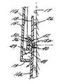
- FIGS. 4 and 5 are enlarged fragmentary sections of the illustrative panel, taken in the planes of lines 4 - 4 and 5 - 5 , respectively in FIG. 3 ;
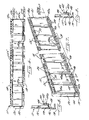
- FIG. 6 is a rear plan view of the panel shown in FIG. 2 ;
- FIG. 7 is an enlarged rear perspective of the panel shown in FIG. 6 ;
- FIGS. 8 and 9 are enlarged fragmentary sections of the illustrated panel taken in the planes of lines 8 - 8 and 9 - 9 , respectively in FIG. 7 ;
- FIG. 10 is a partial plan view showing two installed courses of the wall covering.
- FIGS. 11-13 are enlarged fragmentary sections taken in the planes of lines 11 - 11 , 12 - 12 and 13 - 13 , respectively.
- FIG. 1 of the drawings there is shown an illustrative wall covering 10 comprising a plurality of plastic molded panels 11 in accordance with the present invention.
- the general type of panel employed in the instant invention is described in commonly assigned U.S. Pat. Nos. 5,347,784 and 5,537,792, the disclosures of which are incorporated herein by reference.
- the panels 11 each are formed with simulated building elements.
- the panels 11 are formed with simulated cedar shake shingles 12 of irregular width and length which are disposed in a single row substantially along the length of the panel.
- the simulated shake shingles 12 in this case each have a front face 15 ( FIG. 3 ) extending downwardly and outwardly at a slight taper to a wall or support surface 17 upon which the panel is mounted, and the front face 15 is molded with grooves which simulate the grain of the simulated shake 12 .
- the panels 11 could be formed with other forms of simulated shake shingles, or other types of building materials, such as tile, brick and the like.
- Each panel 11 has an upper horizontal marginal edge region 18 having a substantially uniform width extending across the top of the panel immediately above the row of shake 12 , a lower marginal edge region 19 adjacent an irregular lower peripheral edge of the simulated shake, a side marginal edge region 20 in the form of a laterally-extending flange located to the right-hand side of the last simulated shake 12 in the row, and a marginal edge region 21 on the opposite side of the panel 11 defined by a left-side peripheral edge immediately adjacent the first simulated shake shingle 12 of the row.
- the panels 11 are mounted on a support surface 17 , which may be a wall or roof of a house or other building structure, in horizontal courses with the right-side marginal edge region 20 in underlying relation to the left-side marginal edge region 21 of the panel immediately to the right thereof (as shown in FIG. 13 ) and with the lower marginal edge region 19 of the panels in each course overlying the upper marginal edge region 18 of the panel in the previously installed course immediately below. (see FIGS. 11-12 )
- the panels 11 typically are mounted beginning with the left-hand panel of the lowermost course to be installed on the wall or roof, as is known in the art.
- the second course is installed, immediately above the first course, again starting from the left-hand side.
- the left-hand marginal edge region of the first panel of each row may be appropriately cut square with the left side starting edge of the support surface.
- the panels of the lower most course will be designated with the reference numeral “ 11 a ” and the panels of the subsequent courses will be designated with the reference numerals “ 11 b ”, “ 11 c ” etc. This convention is employed in order to clarify the relative positions and order of installation of the subject panels.
- the upper marginal edge region 18 of each panel 11 is formed with a row of elongated laterally spaced nailing apertures 25 .
- the upper marginal edge region 18 in this instance is formed with rearwardly extending horizontal sealing flanges 26 which surround the nailing apertures and extend substantially the length of the upper marginal edge region 18 ( FIG. 7 ).
- the panels have an interlock arrangement that enables reliable inter-engagement of overlying lower and upper marginal edge regions of the panels upon upward positionable movement of the overlying panel during installation and which facilitates efficient handling of the overlying panel while being secured to the support surface.
- the panels 11 each have a continuous upper interlock rail 30 that extends substantially the length of the panel in forwardly and downwardly directed relation to the upper marginal edge region 18 of the panel that is engageable by a lower upturned interlock rail 40 of an overlying panel, which enables reliable inter-engagement of the panels without the risk of missing individual locking fingers, as in the prior art.
- the illustrative upper interlock rail 30 comprises a continuous downwardly directed interlock flange 36 that extends substantially the entire length of the panel, which is supported by a plurality of longitudinally-spaced horizontal support plates 32 integrally formed with the upper marginal edge region and reinforced by corner joints 35 .
- the horizontal support plates 32 in this case are located between the nailing apertures 25 and the upper edge of the row building elements 12 .
- the upper interlock flange 36 is disposed a distance from the forward surface of the upper marginal edge region 18 for defining a locking flange receiving slot 37 , and a lower terminal end 38 of the locking flange is flared outwardly for guiding the bottom interlock rail 40 of an overlying panel into engaging relation, as will become apparent.
- the upper marginal edge region 18 in this instance is formed with a plurality of laterally-spaced generally rectangular openings 39 which allows tooling to protrude forwardly through the panel to form the locking flange 36 .
- this allows the upper interlock rail 30 to be integrally molded with the panel without the necessity for separate attachment, such as by welding.
- the lower interlock rail 40 while also extending substantially the length of the panel, may comprise a single continuous rail or several relatively-long rail segments 40 a as illustrated, which in this case each extend the width of about three of the simulated shake shingles 12 .
- Each lower interlock rail segment 40 a includes an upturned interlock flange 42 that is easily movable into continuous engaging relation with the interlock flange 36 of the upper rail 30 .
- an upper terminal end 44 of the lower interlock flange 42 is rounded to facilitate sliding, camming engagement with the downwardly-directed interlock flange 36 of the upper rail 30 .
- interlock flanges 36 , 42 of the upper and lower interlock rails 30 , 40 can be easily moved into interlocking relation with each other without cumbersome manipulation of large numbers of small interlock fingers customary of the prior art.
- a cooperative detent arrangement is provided for further locating the interlock flanges 36 , 42 in proper engaging relation to each other and for positively supporting the weight of the overlying panel for sufficient hang time as to enable the installer to secure the panel, such as by nailing or screwing, onto the support surface without manually supporting the weight of they overlying panel.
- a rearward face of the bottom interlock flange 42 is formed with a protruding detent 42 a in the form of an elongated rounded nib that extends horizontally the length of each rail segment 40 a and which is positionable with snap action engagement into a corresponding rounded detent recess 18 a formed in the upper marginal edge region of the underlying panel which extends substantially the length of the panel.
- the interlock flanges 36 , 42 may be designed to forcefully urge the detents 42 a, 18 a into snap action inter-engaging relation with the each other as an incident to upward positioning of the overlying panel during installation. Since the detent ribs and recess 42 a, 18 a extend substantially the entire length of the panels sufficient frictional retention may be achieved to support the weight of the panel for the relatively short hang time necessary for enabling the installer to secure the overlying panel in mounted position. As used herein, the term “hang time” means the time the overlying panel will remain supported by the inter-engaging detents to enable securement of the panel to the support surface without the need for manually supporting the weight of the panel.
- detents 42 a, 18 a serve both to preliminarily locate the overlying panel in aligned relation to the underlying panel during installation and support the panel during securement of the panel in mounted position
- the rounded configuration of the detent nibs 42 a and recess 18 a enable the panel to be selectively slid into and out of engagement, such as may be necessary in allowing the installer to adjust the final position of the overlying panel.
- the configuration of detents 42 a, 18 a further accommodates relative movement of the panels from temperature expansion and contraction of the panels during usage.
- detent ribs 42 a are formed on the rear lower interlock flange 42 and the detent recess 18 a is formed on the front side in the upper marginal edge region 18 of the underlying panel, it will be understood that the reverse arrangement also could be used.
- the interlock flange 42 of the lower interlock rail 40 is supported across a rear side of the row of simulated shake building elements 12 in a manner that does not capture water that might migrate between the panels, which facilitates air circulation through the wall covering following installation, and which does not detract from the natural appearance of the simulated building elements and the installed wall covering.
- the lower interlock flange 42 is supported by a plurality of laterally-spaced vertical support plates 48 that extent outwardly from the rear side of the panel.
- the lower interlock flange 42 in this case has an L-shaped configuration for added structural rigidity, with a base 46 of the L-shaped flange 42 being integrally formed with the vertical support plates 48 .
- the vertical support plates 48 in turn define a plurality of apertures 49 between the rear side of the panel and the interlock flange 42 which permit the free passage of any water that might migrate between the panels during severe weather conditions and which also facilitates the circulation of moisture laden air through the wall covering. Moreover, since the lower interlock flange 42 is supported entirely by the vertical plates 48 , even if during plastic injection molding a faint line of the support plates 48 were visible from a front side of the panel, it will blend into the vertical graining of the simulated shake shingles 12 so as not to affect the aesthetic appearance of the installed wall covering.
- the present invention has particular utility with panels which have a single row of simulated building elements, such as illustrated. Since such panels often are smaller and lighter in weight than panels which have a plurality of rows of building elements, smaller size detents may be utilized which are more readily releasable during adjustable positioning of an overlying panel during installation, as well as from movement during temperature expansion and contraction of the panels. With such single course panels being smaller in size, a multiplicity of panels also may be simultaneously molded in conventional sized molding equipment, with the panels having slightly different shingle patterns for providing a more varied and natural appearance of the finished wall covering.
- the wall covering is formed with the panels in one course being formed with slightly different shingle patterns than the panels in the vertically-adjacent row.
- the panels 11 a and 11 c in the first and third courses may be identically formed and the panels 11 b and 11 d may be identically formed with slightly different characteristics of the simulated shake than the panels 11 a and 11 c .
- Panels with such a single row of simulated building elements have the further advantage that, upon installation, the individual rows the building elements of each panel physically overlap each other, which further enhances the natural appearance of the wall covering.
- the roof and wall panels according to the invention have an interlock arrangement that is adapted for easier and more reliable installation.
- the continuous upper interlock rail facilitates substantially continuous interlocking engagement with a bottom interlock rail of an overlying panel without the cumbersome handling of numerous small interlock fingers which sometimes are missed during installation.
- the cooperating detent arrangement between the overlying lower and upper marginal edge regions of the panels further facilitates proper positioning of the overlying panel during installation, as well as supporting the weight of the panel sufficient to enable the installer to effect its securement on the support surface without cumbersome support of the weight of the panel.
- the bottom interlock flange further is supported transversely across a rear side of the row of simulated building elements in a manner which does not detract from the aesthetic appearance of the wall covering and which facilitates both liquid drainage and air circulation through the installed wall covering.
Abstract
Description
- The present invention relates generally to roof and wall coverings which are primarily intended for outdoor usage, and more particularly, to roof and wall coverings comprised of relatively large panels which each are molded or otherwise formed with decorative patterns characteristic of conventional roofing and siding materials, such as shake shingles, tile, brick or the like.
- Various synthetic roof and wall coverings are known, such as those formed of elongated thermoplastic panels that are nailed or screwed to a wall or roof support surface in horizontal courses or rows in partially overlapping relation to each other so as to provide a substantially water resistant, protective layer over the support surface. Such panels, which usually are identically molded, are commonly formed with a plurality of rows of simulated building elements, such as shake shingles. Because the panels are relatively large, such as up to eight feet and more in length, they can be cumbersome to handle and install, particularly on vertical wall and steep roof surfaces. Since the panels are identically molded, a panel-to-panel identity also can be easily noticed if the panels are not carefully installed. Leakage problems between adjoining panels can also occur under these circumstances.
- Such panels commonly are nailed to the wall or support surface in horizontal courses, beginning with the lower-most course. To enable interlocking engagement between the upper and lower marginal edge regions of vertically-adjacent panels, it is known to provide a plurality of longitudinally-spaced outwardly and downwardly directed interlocked fingers along the upper marginal edge region of the underlying panel which are engaged by a bottom rail formed on the underside of the overlying panel as an incident to upward positioning movement of the panel. Due to the size of the panels it can be difficult for the installer to engage all of the fingers with the upturned rail, with any missed fingers causing an unsightly bowing of the overlying panel, which both detracts from its appearance of the finished wall covering and makes it more susceptible to water entering the juncture between the panels.
- Even when the panel is properly positioned, it can be difficult for the installer to properly hold and maintain a panel and at the same time nail or screw it to the wall surface. Because the upturned interlock rail on the overlying panel extends across a rear side of the simulated shake, even with careful molding, a transverse line of the rail can sometimes be faintly observed from a front side of the panel, which again detracts from the natural appearance of the wall covering. The upturned rail also can undesirably capture and retain water that might migrate between the panels, such as during severe weather conditions.
- It is an object of the present invention to provide a wall covering comprising thermoplastic wall or roof panels which have an interlock arrangement between overlapping upper end marginal edge regions of panels that is adapted for easier and more-reliable engagement during installation.
- Another object is to provide a wall or roof panel as characterized above that facilitates proper positioning of a panel into overlying relation to a previously-installed panel.
- A further object is to provide a panel of the above kind which effects positive interlocking engagement of an overlying panel onto a previously-mounted panel sufficient to support the weight of the panel during securement onto the wall surface. A related object is to provide such a panel interlock arrangement that is releasable to permit adjustable positioning of the panel during installation if necessary, and to accommodate expansion and contraction of the panels from temperature changes during usage.
- Yet another object is to provide a wall or roof panel of the foregoing type which has an upturned interlock rail integrally molded on a rear side of the panel that does not detract from the exterior appearance of the simulated building elements.
- A further object is to provide such a wall panel in which the upturned interlock rail across the rear of the panel facilitates water drainage and air circulation through the completed wall covering.
- Still another object is to provide a wall or roof panel of such type which is relatively simple in construction and which lends itself to economical molding.
- Other objects and advantages of the invention will become apparent upon reading the following detailed description and upon reference to the drawings, in which:
-
FIG. 1 is a plan view of a wall covering comprising panels constructed in accordance with the present invention; -
FIG. 2 is a front plan view of one of the panels of the wall covering shown in FIG. 1.; -
FIG. 3 is an enlarged front perspective of the panel shown inFIG. 2 , with a central portion broken away; -
FIGS. 4 and 5 are enlarged fragmentary sections of the illustrative panel, taken in the planes of lines 4-4 and 5-5, respectively inFIG. 3 ; -
FIG. 6 is a rear plan view of the panel shown inFIG. 2 ; -
FIG. 7 is an enlarged rear perspective of the panel shown inFIG. 6 ; -
FIGS. 8 and 9 are enlarged fragmentary sections of the illustrated panel taken in the planes of lines 8-8 and 9-9, respectively inFIG. 7 ; -
FIG. 10 is a partial plan view showing two installed courses of the wall covering; and -
FIGS. 11-13 are enlarged fragmentary sections taken in the planes of lines 11-11, 12-12 and 13-13, respectively. - While the invention is susceptible of various modifications and alternative constructions, a certain illustrative embodiment thereof has been shown in the drawings and will be described below in detail. It should be understood, however, that there is no intention to limit the invention to the specific form disclosed, but on the contrary, the intention is to cover all modifications, alternative constructions, and equivalents falling within the spirit and scope of the invention.
- Referring now more particularly to
FIG. 1 of the drawings, there is shown an illustrative wall covering 10 comprising a plurality of plastic moldedpanels 11 in accordance with the present invention. The general type of panel employed in the instant invention is described in commonly assigned U.S. Pat. Nos. 5,347,784 and 5,537,792, the disclosures of which are incorporated herein by reference. As shown inFIG. 1 , thepanels 11 each are formed with simulated building elements. In this instance, thepanels 11 are formed with simulatedcedar shake shingles 12 of irregular width and length which are disposed in a single row substantially along the length of the panel. - The simulated
shake shingles 12 in this case each have a front face 15 (FIG. 3 ) extending downwardly and outwardly at a slight taper to a wall orsupport surface 17 upon which the panel is mounted, and thefront face 15 is molded with grooves which simulate the grain of the simulatedshake 12. It will be understood that thepanels 11 could be formed with other forms of simulated shake shingles, or other types of building materials, such as tile, brick and the like. - Each
panel 11 has an upper horizontalmarginal edge region 18 having a substantially uniform width extending across the top of the panel immediately above the row ofshake 12, a lowermarginal edge region 19 adjacent an irregular lower peripheral edge of the simulated shake, a sidemarginal edge region 20 in the form of a laterally-extending flange located to the right-hand side of the last simulatedshake 12 in the row, and amarginal edge region 21 on the opposite side of thepanel 11 defined by a left-side peripheral edge immediately adjacent the first simulatedshake shingle 12 of the row. Thepanels 11 are mounted on asupport surface 17, which may be a wall or roof of a house or other building structure, in horizontal courses with the right-sidemarginal edge region 20 in underlying relation to the left-sidemarginal edge region 21 of the panel immediately to the right thereof (as shown inFIG. 13 ) and with the lowermarginal edge region 19 of the panels in each course overlying the uppermarginal edge region 18 of the panel in the previously installed course immediately below. (seeFIGS. 11-12 ) - The
panels 11 typically are mounted beginning with the left-hand panel of the lowermost course to be installed on the wall or roof, as is known in the art. Upon completion of the first course, the second course is installed, immediately above the first course, again starting from the left-hand side. As is customary in the art, the left-hand marginal edge region of the first panel of each row may be appropriately cut square with the left side starting edge of the support surface. In the following description, when discussing the interaction of panels disposed in vertically displaced courses, the panels of the lower most course will be designated with the reference numeral “11 a” and the panels of the subsequent courses will be designated with the reference numerals “11 b”, “11 c” etc. This convention is employed in order to clarify the relative positions and order of installation of the subject panels. - For securing the
panels 11 to thesupport surface 17, the uppermarginal edge region 18 of eachpanel 11 is formed with a row of elongated laterally spacednailing apertures 25. In order to provide firm support for thepanel 11 on the wall during nailing and for establishing a seal between the rear side of thepanel 11 and thesupport surface 17, the uppermarginal edge region 18 in this instance is formed with rearwardly extendinghorizontal sealing flanges 26 which surround the nailing apertures and extend substantially the length of the upper marginal edge region 18 (FIG. 7 ). Once the uppermarginal edge region 18 is nailed to the support surface, thehorizontal sealing flanges 26 are maintained against thesupport surface 17. - In accordance with the invention, the panels have an interlock arrangement that enables reliable inter-engagement of overlying lower and upper marginal edge regions of the panels upon upward positionable movement of the overlying panel during installation and which facilitates efficient handling of the overlying panel while being secured to the support surface. To this end, the
panels 11 each have a continuousupper interlock rail 30 that extends substantially the length of the panel in forwardly and downwardly directed relation to the uppermarginal edge region 18 of the panel that is engageable by a lowerupturned interlock rail 40 of an overlying panel, which enables reliable inter-engagement of the panels without the risk of missing individual locking fingers, as in the prior art. The illustrativeupper interlock rail 30 comprises a continuous downwardly directedinterlock flange 36 that extends substantially the entire length of the panel, which is supported by a plurality of longitudinally-spacedhorizontal support plates 32 integrally formed with the upper marginal edge region and reinforced by corner joints 35. Thehorizontal support plates 32 in this case are located between thenailing apertures 25 and the upper edge of therow building elements 12. Theupper interlock flange 36 is disposed a distance from the forward surface of the uppermarginal edge region 18 for defining a lockingflange receiving slot 37, and alower terminal end 38 of the locking flange is flared outwardly for guiding thebottom interlock rail 40 of an overlying panel into engaging relation, as will become apparent. To facilitate molding of thecontinuous interlock rail 30 with thepanel 11, the uppermarginal edge region 18 in this instance is formed with a plurality of laterally-spaced generallyrectangular openings 39 which allows tooling to protrude forwardly through the panel to form thelocking flange 36. As will be understood by a person skilled in the art, this allows theupper interlock rail 30 to be integrally molded with the panel without the necessity for separate attachment, such as by welding. - The
lower interlock rail 40, while also extending substantially the length of the panel, may comprise a single continuous rail or several relatively-long rail segments 40a as illustrated, which in this case each extend the width of about three of the simulatedshake shingles 12. Each lower interlock rail segment 40a includes anupturned interlock flange 42 that is easily movable into continuous engaging relation with theinterlock flange 36 of theupper rail 30. To facilitate such inter-engagement, anupper terminal end 44 of thelower interlock flange 42 is rounded to facilitate sliding, camming engagement with the downwardly-directedinterlock flange 36 of theupper rail 30. It can be seen, therefore, that theinterlock flanges lower interlock rails - In keeping with the invention, a cooperative detent arrangement is provided for further locating the
interlock flanges bottom interlock flange 42 is formed with a protrudingdetent 42 a in the form of an elongated rounded nib that extends horizontally the length of each rail segment 40 a and which is positionable with snap action engagement into a corresponding roundeddetent recess 18 a formed in the upper marginal edge region of the underlying panel which extends substantially the length of the panel. It will be understood by a person skilled in the art that theinterlock flanges detents - While the
detents detent nibs 42 a andrecess 18 a enable the panel to be selectively slid into and out of engagement, such as may be necessary in allowing the installer to adjust the final position of the overlying panel. The configuration ofdetents detent ribs 42 a are formed on the rearlower interlock flange 42 and thedetent recess 18 a is formed on the front side in the uppermarginal edge region 18 of the underlying panel, it will be understood that the reverse arrangement also could be used. - In further carrying out the invention, the
interlock flange 42 of thelower interlock rail 40 is supported across a rear side of the row of simulatedshake building elements 12 in a manner that does not capture water that might migrate between the panels, which facilitates air circulation through the wall covering following installation, and which does not detract from the natural appearance of the simulated building elements and the installed wall covering. In the illustrated embodiment, thelower interlock flange 42 is supported by a plurality of laterally-spacedvertical support plates 48 that extent outwardly from the rear side of the panel. Thelower interlock flange 42 in this case has an L-shaped configuration for added structural rigidity, with abase 46 of the L-shapedflange 42 being integrally formed with thevertical support plates 48. Thevertical support plates 48 in turn define a plurality ofapertures 49 between the rear side of the panel and theinterlock flange 42 which permit the free passage of any water that might migrate between the panels during severe weather conditions and which also facilitates the circulation of moisture laden air through the wall covering. Moreover, since thelower interlock flange 42 is supported entirely by thevertical plates 48, even if during plastic injection molding a faint line of thesupport plates 48 were visible from a front side of the panel, it will blend into the vertical graining of thesimulated shake shingles 12 so as not to affect the aesthetic appearance of the installed wall covering. - It will be understood that the present invention has particular utility with panels which have a single row of simulated building elements, such as illustrated. Since such panels often are smaller and lighter in weight than panels which have a plurality of rows of building elements, smaller size detents may be utilized which are more readily releasable during adjustable positioning of an overlying panel during installation, as well as from movement during temperature expansion and contraction of the panels. With such single course panels being smaller in size, a multiplicity of panels also may be simultaneously molded in conventional sized molding equipment, with the panels having slightly different shingle patterns for providing a more varied and natural appearance of the finished wall covering.
- In keeping with this aspect of the invention, in the preferred embodiment, the wall covering is formed with the panels in one course being formed with slightly different shingle patterns than the panels in the vertically-adjacent row. In the wall covering 10 shown in
FIG. 1 , for example, thepanels 11 a and 11 c in the first and third courses may be identically formed and the panels 11 b and 11 d may be identically formed with slightly different characteristics of the simulated shake than thepanels 11 a and 11 c. Panels with such a single row of simulated building elements have the further advantage that, upon installation, the individual rows the building elements of each panel physically overlap each other, which further enhances the natural appearance of the wall covering. Less wastage also is incurred with the use of panels with single row simulated building elements because the cutoff section of the panel that begins a course may be used at the opposite end thereof. Nevertheless, it will be understood that the invention also is applicable to panels which include a plurality of rows of simulated building elements. - From the foregoing, it can been seen that the roof and wall panels according to the invention have an interlock arrangement that is adapted for easier and more reliable installation. The continuous upper interlock rail facilitates substantially continuous interlocking engagement with a bottom interlock rail of an overlying panel without the cumbersome handling of numerous small interlock fingers which sometimes are missed during installation. The cooperating detent arrangement between the overlying lower and upper marginal edge regions of the panels further facilitates proper positioning of the overlying panel during installation, as well as supporting the weight of the panel sufficient to enable the installer to effect its securement on the support surface without cumbersome support of the weight of the panel. The bottom interlock flange further is supported transversely across a rear side of the row of simulated building elements in a manner which does not detract from the aesthetic appearance of the wall covering and which facilitates both liquid drainage and air circulation through the installed wall covering.
Claims (24)
Priority Applications (3)
| Application Number | Priority Date | Filing Date | Title |
|---|---|---|---|
| US11/588,540 US7980037B2 (en) | 2006-10-27 | 2006-10-27 | Decorative wall covering with improved interlock system |
| CA2607308A CA2607308C (en) | 2006-10-27 | 2007-10-23 | Decorative wall covering with improved interlock system |
| US13/163,245 US8074417B2 (en) | 2006-10-27 | 2011-06-17 | Decorative wall covering with improved interlock system |
Applications Claiming Priority (1)
| Application Number | Priority Date | Filing Date | Title |
|---|---|---|---|
| US11/588,540 US7980037B2 (en) | 2006-10-27 | 2006-10-27 | Decorative wall covering with improved interlock system |
Related Child Applications (1)
| Application Number | Title | Priority Date | Filing Date |
|---|---|---|---|
| US13/163,245 Continuation US8074417B2 (en) | 2006-10-27 | 2011-06-17 | Decorative wall covering with improved interlock system |
Publications (2)
| Publication Number | Publication Date |
|---|---|
| US20080098683A1 true US20080098683A1 (en) | 2008-05-01 |
| US7980037B2 US7980037B2 (en) | 2011-07-19 |
Family
ID=39328482
Family Applications (2)
| Application Number | Title | Priority Date | Filing Date |
|---|---|---|---|
| US11/588,540 Active 2027-08-22 US7980037B2 (en) | 2006-10-27 | 2006-10-27 | Decorative wall covering with improved interlock system |
| US13/163,245 Active US8074417B2 (en) | 2006-10-27 | 2011-06-17 | Decorative wall covering with improved interlock system |
Family Applications After (1)
| Application Number | Title | Priority Date | Filing Date |
|---|---|---|---|
| US13/163,245 Active US8074417B2 (en) | 2006-10-27 | 2011-06-17 | Decorative wall covering with improved interlock system |
Country Status (2)
| Country | Link |
|---|---|
| US (2) | US7980037B2 (en) |
| CA (1) | CA2607308C (en) |
Cited By (11)
| Publication number | Priority date | Publication date | Assignee | Title |
|---|---|---|---|---|
| US20090084058A1 (en) * | 2007-09-28 | 2009-04-02 | John Cahill | Plastic siding panel |
| US20100011690A1 (en) * | 2007-02-05 | 2010-01-21 | Exteria Building Products | Roof and wall covering with improved corner construction |
| USD648038S1 (en) | 2010-06-04 | 2011-11-01 | Novik, Inc. | Shingle |
| US8074417B2 (en) | 2006-10-27 | 2011-12-13 | Exteria Building Products, Llc | Decorative wall covering with improved interlock system |
| US8209938B2 (en) | 2010-03-08 | 2012-07-03 | Novik, Inc. | Siding and roofing panel with interlock system |
| US8555581B2 (en) | 2011-06-21 | 2013-10-15 | Victor Amend | Exterior wall finishing arrangement |
| US8950135B2 (en) | 2012-12-19 | 2015-02-10 | Novik Inc. | Corner assembly for siding and roofing coverings and method for covering a corner using same |
| US9206827B2 (en) | 2012-11-20 | 2015-12-08 | Avery Dennison Corporation | Wall mount organization system |
| US9388565B2 (en) | 2012-12-20 | 2016-07-12 | Novik Inc. | Siding and roofing panels and method for mounting same |
| CN109736520A (en) * | 2019-01-14 | 2019-05-10 | 龚柱 | The laying method of wall cladding sheets |
| US20210301542A1 (en) * | 2018-03-30 | 2021-09-30 | Certainteed Llc | Exterior cladding panels and methods for installing them |
Families Citing this family (23)
| Publication number | Priority date | Publication date | Assignee | Title |
|---|---|---|---|---|
| US7694477B2 (en) * | 2006-02-10 | 2010-04-13 | Peter Kuelker | Hangerless precast cladding panel system |
| US8782988B2 (en) * | 2008-02-06 | 2014-07-22 | Boral Stone Products Llc | Prefabricated wall panel with tongue and groove construction |
| US9091086B2 (en) | 2013-01-21 | 2015-07-28 | Tapco International Corporation | Siding panel system with randomized elements |
| US8915036B2 (en) * | 2013-03-08 | 2014-12-23 | Quality Edge, Inc. | Formed interlocking roofing panels |
| CA3113731C (en) | 2013-03-15 | 2023-07-11 | Certainteed Corporation | Variegated building product and method |
| US9884443B2 (en) | 2013-03-15 | 2018-02-06 | Certainteed Corporation | System, method and article for siding corner |
| US8898977B2 (en) | 2013-03-15 | 2014-12-02 | Francesco Gulino | Wedge-lock quoin corner assembly |
| CA2874660C (en) | 2013-12-18 | 2021-09-14 | Stephen W. Steffes | Panel siding product |
| CA2875534C (en) | 2013-12-18 | 2018-09-25 | Certainteed Corporation | Single panel siding product |
| USD738541S1 (en) * | 2014-02-12 | 2015-09-08 | Metrolite Manufacturing | Steel sheet roof tile |
| USD780952S1 (en) * | 2014-08-27 | 2017-03-07 | Royal Group, Inc. | Simulated shake panel |
| USD779684S1 (en) * | 2014-08-27 | 2017-02-21 | Royal Group, Inc. | Simulated shake panel |
| USD792615S1 (en) * | 2014-12-12 | 2017-07-18 | Certainteed Corporation | Siding panel |
| USD761447S1 (en) | 2015-01-27 | 2016-07-12 | Building Materials Investment Corporation | Roofing panel |
| USD765271S1 (en) | 2015-01-27 | 2016-08-30 | Building Materials Investment Corporation | Roofing panel |
| USD764687S1 (en) | 2015-01-27 | 2016-08-23 | Building Materials Investment Corporation | Roofing panel |
| USD765272S1 (en) | 2015-01-27 | 2016-08-30 | Building Materials Investment Corporation | Roofing panel |
| US11332943B2 (en) | 2019-10-08 | 2022-05-17 | D.A. Distribution Inc. | Wall covering with adjustable spacing |
| US11566426B2 (en) | 2019-11-26 | 2023-01-31 | Bmic Llc | Roofing panels with water shedding features |
| WO2021202327A1 (en) | 2020-03-30 | 2021-10-07 | Building Materials Investment Corporation | Interlocking laminated structural roofing panels |
| MX2021013676A (en) | 2020-11-09 | 2022-05-10 | Bmic Llc | Interlocking structural roofing panels with integrated solar panels. |
| CA3141207A1 (en) * | 2020-12-07 | 2022-06-07 | ACM Panelworx Inc. | Modular panels, systems, and methods of assembly |
| MX2022006329A (en) | 2021-05-25 | 2022-11-28 | Bmic Llc | Panelized roofing system. |
Citations (45)
| Publication number | Priority date | Publication date | Assignee | Title |
|---|---|---|---|---|
| US130156A (en) * | 1872-08-06 | Improvement in roofing-tiles | ||
| US1124001A (en) * | 1913-10-09 | 1915-01-05 | Edgar P Elzey | Roofing-tile and the like. |
| US1559967A (en) * | 1923-02-17 | 1925-11-03 | George B King | Sheet-metal roofing |
| US1572377A (en) * | 1925-03-20 | 1926-02-09 | Frank M Blair | Enamel metal shingle |
| US2659323A (en) * | 1951-06-05 | 1953-11-17 | Homasote Company | Roofing or siding assembly |
| US2766706A (en) * | 1949-06-17 | 1956-10-16 | Ludowici Wilhelm | Gutter pantiles |
| US2766861A (en) * | 1952-06-05 | 1956-10-16 | Abramson Harry | Building wall sidings |
| US2811118A (en) * | 1953-07-13 | 1957-10-29 | Francis M Ball | Shingles |
| US3158960A (en) * | 1961-09-22 | 1964-12-01 | Building Products Ltd | Siding panels |
| US3188774A (en) * | 1962-08-29 | 1965-06-15 | Mccorkle Carl | Metal siding structure |
| US3214876A (en) * | 1962-12-10 | 1965-11-02 | Mastic Corp | Nail anchored building siding |
| US3233382A (en) * | 1962-08-30 | 1966-02-08 | Alside Inc | Aluminum siding panel having interlocking marginal edges |
| US3417531A (en) * | 1966-10-21 | 1968-12-24 | Robert B. Jones | Aluminum and vinyl sidings |
| US3613326A (en) * | 1969-10-03 | 1971-10-19 | Alside Int Corp | Preformed simulated brick panel having stepped edges |
| US4102106A (en) * | 1976-12-28 | 1978-07-25 | Gaf Corporation | Siding panel |
| US4223490A (en) * | 1979-04-13 | 1980-09-23 | Medow Robert S | Spacing means for wall panels |
| US4334396A (en) * | 1978-05-30 | 1982-06-15 | The Anaconda Company | Interconnecting lock construction for siding, soffits and related construction elements |
| US4468909A (en) * | 1982-05-03 | 1984-09-04 | Masonite Corporation | Building panel |
| US4680911A (en) * | 1986-05-21 | 1987-07-21 | Davis Richard A | Decorative wall covering |
| US4731969A (en) * | 1984-09-12 | 1988-03-22 | Redland Roof Tiles Limited | Roof tiles |
| US5072562A (en) * | 1990-03-05 | 1991-12-17 | Nailite International | Decorative wall covering |
| US5074093A (en) * | 1988-01-26 | 1991-12-24 | Meadows David F | Overlapping architectural tiles |
| US5305570A (en) * | 1992-10-09 | 1994-04-26 | Melchor Rodriguez | Panel element for forming a continuous covering on a building |
| US5537792A (en) * | 1995-03-23 | 1996-07-23 | Nailite International | Decorative wall covering |
| US5644886A (en) * | 1994-10-31 | 1997-07-08 | Ellert Ekmark | Roofing |
| US5675955A (en) * | 1995-09-01 | 1997-10-14 | Champagne; Wendel James | System for covering exterior building surfaces |
| US5791093A (en) * | 1997-03-19 | 1998-08-11 | Goer Manufacturing Company, Inc. | Slatwall panel and method of assembling same |
| US5878543A (en) * | 1998-03-17 | 1999-03-09 | Associated Materials, Incorporated | Interlocking siding panel |
| US5916100A (en) * | 1997-12-12 | 1999-06-29 | ? Elward Systems Corporation | Method and apparatus for erecting wall panels |
| US6082064A (en) * | 1997-12-12 | 2000-07-04 | Elward Systems Corporation | Method and apparatus for sealing wall panels |
| US6224701B1 (en) * | 1999-09-08 | 2001-05-01 | Alcoa Inc. | Molded plastic siding panel |
| US6295777B1 (en) * | 1997-11-19 | 2001-10-02 | Certainteed Corporation | Exterior finishing panel |
| US6336303B1 (en) * | 1999-05-07 | 2002-01-08 | Atlantis Plastics, Inc. | Injection molded exterior siding panel with positioning relief and method of installation |
| US6490835B1 (en) * | 2001-09-24 | 2002-12-10 | William G. Simmons | Vinyl siding wall ornamentation |
| US6526718B2 (en) * | 1998-03-26 | 2003-03-04 | Crane Plastics Company Llc | Reinforced vinyl siding |
| US6715250B2 (en) * | 1999-09-08 | 2004-04-06 | Alcoa Inc. | Plastic siding panel |
| US20050072093A1 (en) * | 1998-05-22 | 2005-04-07 | King Daniel W. | Continuous production of plastic siding panels with separate shingle appearance |
| US20050102946A1 (en) * | 2003-10-30 | 2005-05-19 | Stucky David J. | Siding panel tab and slot joint |
| USD507837S1 (en) * | 2004-06-10 | 2005-07-26 | Tapco International Corporation | Shake siding panel |
| US6976342B1 (en) * | 1999-11-29 | 2005-12-20 | Peter Kowalevich | Fully interlocking synthetic, simulated shake siding |
| US7240461B1 (en) * | 2001-10-31 | 2007-07-10 | Atlantis Plastics, Inc. | Siding panels for wall coverings |
| US20080083186A1 (en) * | 2006-10-04 | 2008-04-10 | Novik, Inc. | Roofing panels and roofing system employing the same |
| US7698865B2 (en) * | 2004-01-08 | 2010-04-20 | Tecton Products, Llc | Pultruded building product |
| US7739848B2 (en) * | 2005-01-12 | 2010-06-22 | Kathy Trout | Roofing panel interlock system |
| US7775009B2 (en) * | 2005-12-22 | 2010-08-17 | Tapco International Corporation | System for providing a decorative covering on a support surface using panels with interlocks |
Family Cites Families (27)
| Publication number | Priority date | Publication date | Assignee | Title |
|---|---|---|---|---|
| US478171A (en) * | 1892-07-05 | Roofing-tile | ||
| US1589675A (en) * | 1925-10-05 | 1926-06-22 | George A Belding | Sheet-metal shingle |
| US2607449A (en) * | 1947-11-05 | 1952-08-19 | Sheldon Blocker H | Sheet metal siding |
| US3159943A (en) * | 1960-03-30 | 1964-12-08 | Alsco Inc | Composite building siding |
| US3289365A (en) * | 1963-12-03 | 1966-12-06 | Aluminum Ass | Electrical continuity for aluminum siding |
| US3325952A (en) * | 1964-12-08 | 1967-06-20 | Sam Z Trachtenberg | Metal siding with snap acting interlock |
| US3473274A (en) * | 1967-07-19 | 1969-10-21 | Diamond Shamrock Corp | Siding assembly |
| US3593479A (en) * | 1969-01-31 | 1971-07-20 | Bird & Son | Molded plastic siding units |
| BE783810A (en) * | 1971-06-25 | 1972-09-18 | Oscar Joseph | TILE AND ITS MANUFACTURING PROCESS |
| US4450665A (en) * | 1981-07-10 | 1984-05-29 | Vinyl Improvement Products Company | Interlocking building siding |
| JPH07103666B2 (en) * | 1988-02-12 | 1995-11-08 | 株式会社アイジー技術研究所 | Outer wall structure |
| JP2661719B2 (en) * | 1988-09-22 | 1997-10-08 | 昭和電工建材株式会社 | Ventilation method |
| US5076037A (en) | 1990-03-02 | 1991-12-31 | Nailite International | Decorative wall cover and method of installation |
| DE4006772C2 (en) * | 1990-03-03 | 1994-04-21 | Heinz Wacker | Roof covering made of roof covering plates with overlapping longitudinal and transverse edges |
| JPH0427059A (en) * | 1990-05-21 | 1992-01-30 | Sekisui Chem Co Ltd | Roof tile |
| US5249402A (en) | 1991-04-09 | 1993-10-05 | Crick Dallas M | Decorative wall covering |
| US5347784A (en) | 1992-12-28 | 1994-09-20 | Nailite International | Decorative wall covering with improved interlock and corner construction |
| US5455099A (en) * | 1994-09-06 | 1995-10-03 | Banner; Norman | Vinyl shake |
| US6319456B1 (en) * | 1998-11-12 | 2001-11-20 | Certainteed Corporation | Method for continuous vacuum forming shaped polymeric articles |
| US6370832B1 (en) * | 1999-05-28 | 2002-04-16 | Associated Materials, Inc. | Interlocking panel with channel nailing hem |
| US6955019B2 (en) | 2002-05-10 | 2005-10-18 | Nailite International | Decorative wall covering with upward movement panel interlock system |
| US6941707B2 (en) * | 2003-05-02 | 2005-09-13 | Certainteed Corporation | Vented soffit panel |
| US7698864B2 (en) * | 2005-07-14 | 2010-04-20 | Atlantis Plastics, Inc. | Bonded siding panels |
| US20070107356A1 (en) * | 2005-11-01 | 2007-05-17 | Certainteed Corporation | Staggered look shake siding panel with improved locking mechanism |
| US7694477B2 (en) * | 2006-02-10 | 2010-04-13 | Peter Kuelker | Hangerless precast cladding panel system |
| US7980037B2 (en) | 2006-10-27 | 2011-07-19 | Exteria Building Products, Llc | Decorative wall covering with improved interlock system |
| US7735286B2 (en) * | 2007-02-05 | 2010-06-15 | Exteria Building Products | Roof and wall covering with improved corner construction |
-
2006
- 2006-10-27 US US11/588,540 patent/US7980037B2/en active Active
-
2007
- 2007-10-23 CA CA2607308A patent/CA2607308C/en active Active
-
2011
- 2011-06-17 US US13/163,245 patent/US8074417B2/en active Active
Patent Citations (49)
| Publication number | Priority date | Publication date | Assignee | Title |
|---|---|---|---|---|
| US130156A (en) * | 1872-08-06 | Improvement in roofing-tiles | ||
| US1124001A (en) * | 1913-10-09 | 1915-01-05 | Edgar P Elzey | Roofing-tile and the like. |
| US1559967A (en) * | 1923-02-17 | 1925-11-03 | George B King | Sheet-metal roofing |
| US1572377A (en) * | 1925-03-20 | 1926-02-09 | Frank M Blair | Enamel metal shingle |
| US2766706A (en) * | 1949-06-17 | 1956-10-16 | Ludowici Wilhelm | Gutter pantiles |
| US2659323A (en) * | 1951-06-05 | 1953-11-17 | Homasote Company | Roofing or siding assembly |
| US2766861A (en) * | 1952-06-05 | 1956-10-16 | Abramson Harry | Building wall sidings |
| US2811118A (en) * | 1953-07-13 | 1957-10-29 | Francis M Ball | Shingles |
| US3158960A (en) * | 1961-09-22 | 1964-12-01 | Building Products Ltd | Siding panels |
| US3188774A (en) * | 1962-08-29 | 1965-06-15 | Mccorkle Carl | Metal siding structure |
| US3233382A (en) * | 1962-08-30 | 1966-02-08 | Alside Inc | Aluminum siding panel having interlocking marginal edges |
| US3214876A (en) * | 1962-12-10 | 1965-11-02 | Mastic Corp | Nail anchored building siding |
| US3417531A (en) * | 1966-10-21 | 1968-12-24 | Robert B. Jones | Aluminum and vinyl sidings |
| US3613326A (en) * | 1969-10-03 | 1971-10-19 | Alside Int Corp | Preformed simulated brick panel having stepped edges |
| US4102106A (en) * | 1976-12-28 | 1978-07-25 | Gaf Corporation | Siding panel |
| US4334396A (en) * | 1978-05-30 | 1982-06-15 | The Anaconda Company | Interconnecting lock construction for siding, soffits and related construction elements |
| US4223490A (en) * | 1979-04-13 | 1980-09-23 | Medow Robert S | Spacing means for wall panels |
| US4468909A (en) * | 1982-05-03 | 1984-09-04 | Masonite Corporation | Building panel |
| US4731969A (en) * | 1984-09-12 | 1988-03-22 | Redland Roof Tiles Limited | Roof tiles |
| US4680911A (en) * | 1986-05-21 | 1987-07-21 | Davis Richard A | Decorative wall covering |
| US5074093A (en) * | 1988-01-26 | 1991-12-24 | Meadows David F | Overlapping architectural tiles |
| US5072562A (en) * | 1990-03-05 | 1991-12-17 | Nailite International | Decorative wall covering |
| US5305570A (en) * | 1992-10-09 | 1994-04-26 | Melchor Rodriguez | Panel element for forming a continuous covering on a building |
| US5644886A (en) * | 1994-10-31 | 1997-07-08 | Ellert Ekmark | Roofing |
| US5537792A (en) * | 1995-03-23 | 1996-07-23 | Nailite International | Decorative wall covering |
| US5675955A (en) * | 1995-09-01 | 1997-10-14 | Champagne; Wendel James | System for covering exterior building surfaces |
| US5791093A (en) * | 1997-03-19 | 1998-08-11 | Goer Manufacturing Company, Inc. | Slatwall panel and method of assembling same |
| US6295777B1 (en) * | 1997-11-19 | 2001-10-02 | Certainteed Corporation | Exterior finishing panel |
| US20020026758A1 (en) * | 1997-12-12 | 2002-03-07 | Elward Systems Corporation | Method and apparatus for erecting wall panels |
| US5916100A (en) * | 1997-12-12 | 1999-06-29 | ? Elward Systems Corporation | Method and apparatus for erecting wall panels |
| US6082064A (en) * | 1997-12-12 | 2000-07-04 | Elward Systems Corporation | Method and apparatus for sealing wall panels |
| US5878543A (en) * | 1998-03-17 | 1999-03-09 | Associated Materials, Incorporated | Interlocking siding panel |
| US6526718B2 (en) * | 1998-03-26 | 2003-03-04 | Crane Plastics Company Llc | Reinforced vinyl siding |
| US7008213B2 (en) * | 1998-05-22 | 2006-03-07 | Tapco International Corporation | Continuous production of plastic siding panels with separate shingle appearance |
| US20050072093A1 (en) * | 1998-05-22 | 2005-04-07 | King Daniel W. | Continuous production of plastic siding panels with separate shingle appearance |
| US6336303B1 (en) * | 1999-05-07 | 2002-01-08 | Atlantis Plastics, Inc. | Injection molded exterior siding panel with positioning relief and method of installation |
| US6224701B1 (en) * | 1999-09-08 | 2001-05-01 | Alcoa Inc. | Molded plastic siding panel |
| US6715250B2 (en) * | 1999-09-08 | 2004-04-06 | Alcoa Inc. | Plastic siding panel |
| US6421975B2 (en) * | 1999-09-08 | 2002-07-23 | Alcoa Inc. | Molded plastic siding panel |
| US6976342B1 (en) * | 1999-11-29 | 2005-12-20 | Peter Kowalevich | Fully interlocking synthetic, simulated shake siding |
| US6490835B1 (en) * | 2001-09-24 | 2002-12-10 | William G. Simmons | Vinyl siding wall ornamentation |
| US7240461B1 (en) * | 2001-10-31 | 2007-07-10 | Atlantis Plastics, Inc. | Siding panels for wall coverings |
| US7207145B2 (en) * | 2003-10-30 | 2007-04-24 | Certainteed Corporation | Siding panel tab and slot joint |
| US20050102946A1 (en) * | 2003-10-30 | 2005-05-19 | Stucky David J. | Siding panel tab and slot joint |
| US7698865B2 (en) * | 2004-01-08 | 2010-04-20 | Tecton Products, Llc | Pultruded building product |
| USD507837S1 (en) * | 2004-06-10 | 2005-07-26 | Tapco International Corporation | Shake siding panel |
| US7739848B2 (en) * | 2005-01-12 | 2010-06-22 | Kathy Trout | Roofing panel interlock system |
| US7775009B2 (en) * | 2005-12-22 | 2010-08-17 | Tapco International Corporation | System for providing a decorative covering on a support surface using panels with interlocks |
| US20080083186A1 (en) * | 2006-10-04 | 2008-04-10 | Novik, Inc. | Roofing panels and roofing system employing the same |
Cited By (16)
| Publication number | Priority date | Publication date | Assignee | Title |
|---|---|---|---|---|
| US8074417B2 (en) | 2006-10-27 | 2011-12-13 | Exteria Building Products, Llc | Decorative wall covering with improved interlock system |
| US20100011690A1 (en) * | 2007-02-05 | 2010-01-21 | Exteria Building Products | Roof and wall covering with improved corner construction |
| US8136316B2 (en) * | 2007-02-05 | 2012-03-20 | Exteria Building Products, Llc | Roof and wall covering with improved corner construction |
| US8601764B2 (en) | 2007-09-28 | 2013-12-10 | National Shelter Products | Plastic siding panel |
| US8407962B2 (en) * | 2007-09-28 | 2013-04-02 | National Shelter Products | Plastic siding panel |
| US20090084058A1 (en) * | 2007-09-28 | 2009-04-02 | John Cahill | Plastic siding panel |
| US8209938B2 (en) | 2010-03-08 | 2012-07-03 | Novik, Inc. | Siding and roofing panel with interlock system |
| USD648038S1 (en) | 2010-06-04 | 2011-11-01 | Novik, Inc. | Shingle |
| US8555581B2 (en) | 2011-06-21 | 2013-10-15 | Victor Amend | Exterior wall finishing arrangement |
| US9206827B2 (en) | 2012-11-20 | 2015-12-08 | Avery Dennison Corporation | Wall mount organization system |
| US10231556B2 (en) | 2012-11-20 | 2019-03-19 | Ccl Label, Inc. | Wall mount organization system |
| US8950135B2 (en) | 2012-12-19 | 2015-02-10 | Novik Inc. | Corner assembly for siding and roofing coverings and method for covering a corner using same |
| US9388565B2 (en) | 2012-12-20 | 2016-07-12 | Novik Inc. | Siding and roofing panels and method for mounting same |
| US20210301542A1 (en) * | 2018-03-30 | 2021-09-30 | Certainteed Llc | Exterior cladding panels and methods for installing them |
| US11732483B2 (en) * | 2018-03-30 | 2023-08-22 | Certainteed Llc | Exterior cladding panels and methods for installing them |
| CN109736520A (en) * | 2019-01-14 | 2019-05-10 | 龚柱 | The laying method of wall cladding sheets |
Also Published As
| Publication number | Publication date |
|---|---|
| US20110265417A1 (en) | 2011-11-03 |
| CA2607308C (en) | 2013-04-30 |
| US8074417B2 (en) | 2011-12-13 |
| CA2607308A1 (en) | 2008-04-27 |
| US7980037B2 (en) | 2011-07-19 |
Similar Documents
| Publication | Publication Date | Title |
|---|---|---|
| US7980037B2 (en) | Decorative wall covering with improved interlock system | |
| US7735286B2 (en) | Roof and wall covering with improved corner construction | |
| US6955019B2 (en) | Decorative wall covering with upward movement panel interlock system | |
| US7587871B2 (en) | Simulated hand laid brick and mortar wall covering | |
| US5347784A (en) | Decorative wall covering with improved interlock and corner construction | |
| US5249402A (en) | Decorative wall covering | |
| CA2302598C (en) | Injection molded exterior siding panel with positioning relief and method of installation | |
| US7784222B2 (en) | Siding system and method | |
| US5694728A (en) | Vinyl siding system | |
| US3325952A (en) | Metal siding with snap acting interlock | |
| CA1138172A (en) | Horizontal siding panel system with vertical stringers | |
| US8407962B2 (en) | Plastic siding panel | |
| US6073398A (en) | Gutter cover | |
| US8151530B2 (en) | Simulated masonry wall panel with improved interlock system | |
| US7127869B2 (en) | Wall covering with improved corner molding and method of installation | |
| US7228665B2 (en) | Roof and wall covering with improved corner construction | |
| US8136316B2 (en) | Roof and wall covering with improved corner construction | |
| US20070107356A1 (en) | Staggered look shake siding panel with improved locking mechanism | |
| US9388565B2 (en) | Siding and roofing panels and method for mounting same | |
| JP3031597B2 (en) | Interlocking construction panel | |
| CA2838061C (en) | Corner assembly for siding and roofing coverings and method for covering a corner using same | |
| US20050204647A1 (en) | Molded roof flashing system | |
| US20030046878A1 (en) | Molded roof flashing system | |
| CA2037429C (en) | Decorative wall covering and method of installation |
Legal Events
| Date | Code | Title | Description |
|---|---|---|---|
| AS | Assignment |
Owner name: NAILITE INTERNATIONAL, FLORIDA Free format text: ASSIGNMENT OF ASSIGNORS INTEREST;ASSIGNORS:TRABUE, ROBERT;SCHWARZ, STEFAN;REEL/FRAME:018644/0779 Effective date: 20061030 |
|
| AS | Assignment |
Owner name: NAILITE INTERNATIONAL, FLORIDA Free format text: ASSIGNMENT OF ASSIGNORS INTEREST;ASSIGNORS:TRABUE, ROBERT;SCHWARZ, STEFAN;REEL/FRAME:018646/0208 Effective date: 20061030 |
|
| AS | Assignment |
Owner name: EXTERIA BUILDING PRODUCTS, LLC, FLORIDA Free format text: ASSIGNMENT OF ASSIGNORS INTEREST;ASSIGNOR:NAILITE INTERNATIONAL, INC.;REEL/FRAME:022689/0415 Effective date: 20090413 Owner name: EXTERIA BUILDING PRODUCTS, LLC,FLORIDA Free format text: ASSIGNMENT OF ASSIGNORS INTEREST;ASSIGNOR:NAILITE INTERNATIONAL, INC.;REEL/FRAME:022689/0415 Effective date: 20090413 |
|
| STCF | Information on status: patent grant |
Free format text: PATENTED CASE |
|
| FPAY | Fee payment |
Year of fee payment: 4 |
|
| AS | Assignment |
Owner name: BANK OF MONTREAL, CANADA Free format text: SECURITY AGREEMENT;ASSIGNOR:EXTERIA BUILDING PRODUCTS, LLC;REEL/FRAME:039070/0144 Effective date: 20160615 |
|
| AS | Assignment |
Owner name: DERBY BUILDING PRODUCTS, LLC, FLORIDA Free format text: CHANGE OF NAME;ASSIGNOR:EXTERIA BUILDING PRODUCTS, LLC;REEL/FRAME:042147/0335 Effective date: 20170215 |
|
| MAFP | Maintenance fee payment |
Free format text: PAYMENT OF MAINTENANCE FEE, 8TH YR, SMALL ENTITY (ORIGINAL EVENT CODE: M2552); ENTITY STATUS OF PATENT OWNER: SMALL ENTITY Year of fee payment: 8 |
|
| AS | Assignment |
Owner name: DERBY BUILDING PRODUCTS INC., CANADA Free format text: ASSIGNMENT OF ASSIGNORS INTEREST;ASSIGNOR:DERBY BUILDING PRODUCTS LLC;REEL/FRAME:055872/0929 Effective date: 20210309 |
|
| MAFP | Maintenance fee payment |
Free format text: PAYMENT OF MAINTENANCE FEE, 12TH YR, SMALL ENTITY (ORIGINAL EVENT CODE: M2553); ENTITY STATUS OF PATENT OWNER: SMALL ENTITY Year of fee payment: 12 |