US20080098680A1 - Three-dimensional cover tile - Google Patents
Three-dimensional cover tile Download PDFInfo
- Publication number
- US20080098680A1 US20080098680A1 US11/590,618 US59061806A US2008098680A1 US 20080098680 A1 US20080098680 A1 US 20080098680A1 US 59061806 A US59061806 A US 59061806A US 2008098680 A1 US2008098680 A1 US 2008098680A1
- Authority
- US
- United States
- Prior art keywords
- panel
- cover tile
- back panel
- edge portions
- wall
- Prior art date
- Legal status (The legal status is an assumption and is not a legal conclusion. Google has not performed a legal analysis and makes no representation as to the accuracy of the status listed.)
- Abandoned
Links
- 238000003860 storage Methods 0.000 claims abstract description 34
- 238000009423 ventilation Methods 0.000 claims description 12
- 239000000463 material Substances 0.000 claims description 6
- 230000037431 insertion Effects 0.000 claims 3
- 238000003780 insertion Methods 0.000 claims 3
- 230000015572 biosynthetic process Effects 0.000 abstract description 2
- 238000005755 formation reaction Methods 0.000 abstract description 2
- 239000004744 fabric Substances 0.000 description 4
- 239000003351 stiffener Substances 0.000 description 4
- 239000000853 adhesive Substances 0.000 description 2
- 230000001070 adhesive effect Effects 0.000 description 2
- 230000002093 peripheral effect Effects 0.000 description 2
- 238000010276 construction Methods 0.000 description 1
- 230000000994 depressogenic effect Effects 0.000 description 1
- 230000005611 electricity Effects 0.000 description 1
- 238000010438 heat treatment Methods 0.000 description 1
- 230000008676 import Effects 0.000 description 1
- 238000012432 intermediate storage Methods 0.000 description 1
- 239000002184 metal Substances 0.000 description 1
- 238000012986 modification Methods 0.000 description 1
- 230000004048 modification Effects 0.000 description 1
- 239000002991 molded plastic Substances 0.000 description 1
- 230000008707 rearrangement Effects 0.000 description 1
- 238000003466 welding Methods 0.000 description 1
Images

Classifications
-
- E—FIXED CONSTRUCTIONS
- E04—BUILDING
- E04B—GENERAL BUILDING CONSTRUCTIONS; WALLS, e.g. PARTITIONS; ROOFS; FLOORS; CEILINGS; INSULATION OR OTHER PROTECTION OF BUILDINGS
- E04B2/00—Walls, e.g. partitions, for buildings; Wall construction with regard to insulation; Connections specially adapted to walls
- E04B2/74—Removable non-load-bearing partitions; Partitions with a free upper edge
- E04B2/7407—Removable non-load-bearing partitions; Partitions with a free upper edge assembled using frames with infill panels or coverings only; made-up of panels and a support structure incorporating posts
- E04B2/7416—Removable non-load-bearing partitions; Partitions with a free upper edge assembled using frames with infill panels or coverings only; made-up of panels and a support structure incorporating posts with free upper edge, e.g. for use as office space dividers
-
- E—FIXED CONSTRUCTIONS
- E04—BUILDING
- E04B—GENERAL BUILDING CONSTRUCTIONS; WALLS, e.g. PARTITIONS; ROOFS; FLOORS; CEILINGS; INSULATION OR OTHER PROTECTION OF BUILDINGS
- E04B2/00—Walls, e.g. partitions, for buildings; Wall construction with regard to insulation; Connections specially adapted to walls
- E04B2/74—Removable non-load-bearing partitions; Partitions with a free upper edge
- E04B2002/7483—Details of furniture, e.g. tables or shelves, associated with the partitions
Definitions
- the invention relates to a wall panel system having one or more three-dimensional cover tiles, and in particular, to a cover tile for such a wall panel system which serves to not only cover the interior of a wall panel but also serve additional functions such as storage or ventilation.
- Such wall panel systems comprise an interior panel frame defining open areas within the frame, and a plurality of substantially flat or planar cover tiles which are removably mounted onto the frame so as to overlie and cover the open frame interior.
- planar cover tiles are substantially flat in the vertical dimension and have outward facing exterior surfaces which define the finished aesthetic appearance of the wall panel.
- the finished exterior surface of the cover tile typically is flat or at least has an exposed surface texture, such as fabric, which serves an aesthetic function.
- such systems further include various add-on accessories and structures which mount to the panel frame separate from the cover tile and are disposed outwardly of the cover tile surface to provide for storage in office areas or workstations defined by the wall panel system.
- add-on accessories may include overhead storage units, shelving, and racks on which additional shelves and smaller accessories are hung.
- Such systems require components separate from the cover tiles and result in additional complexity for the wall panel system since it requires a mounting arrangement not only for the cover tiles but also for the add-on accessories. Further, such accessories project outwardly of the face of the cover tile surfaces a noticeable distance which may be undesirable in some environments and specific applications.
- the invention thereby relates to a wall panel system comprising a basic wall panel frame defining an open interior therein.
- the invention further includes one or more three-dimensional cover tiles which each extend laterally across the width of its respective wall panel frame and extend a pre-defined vertical distance so as to overlie and enclose at least a portion, if not all, of an open interior region of the wall panel frame.
- these three-dimensional cover tiles are formed so as to have a back portion which includes tile connectors thereon that are removably engagable with the wall panel frame.
- the cover tiles further include front portions which project outwardly a necessary distance away from the back portion and are configured to include storage formations therein such as pockets and the like.
- Sections of the front and back portions of the cover tile have exposed exterior surfaces which define the aesthetic face of the wall panel frame when provided in combination with other three-dimensional cover tiles and/or planar cover tiles.
- these three-dimensional cover tiles define a storage capacity and/or other different functional capacities in the cover tile since the cover tile is enlarged in three dimensions, not only laterally and vertically, but also outwardly away from the panel frame.
- This additional storage capacity is provided in a limited outward depth so that the thickness of the cover tile is still relatively shallow and provides the desired storage capacity in a smaller outward distance as compared to conventional add-on components which mount over the face of a conventional planar cover tile.
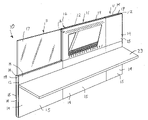
- FIG. 1 is a perspective view of a wall panel arrangement have a three-dimensional cover tile mounted thereto.
- FIG. 2 is a front elevational view of an assembled three-dimensional cover tile.
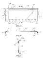
- FIG. 3 is a front view of a back panel of the cover tile assembly.
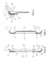
- FIG. 4 is a side cross-sectional view of the back panel as taken along line 4 - 4 of FIG. 3 .
- FIG. 5 is a side cross-sectional view as taken along line 5 - 5 of FIG. 3 .
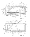
- FIG. 6 is a partial side cross-sectional view of the tile assembly as taken along line 6 - 6 of FIG. 2 .
- FIG. 7 is a front view of a front panel of the cover tile assembly.
- FIG. 8 is a bottom cross-sectional view of the front panel as taken along line 8 - 8 of FIG. 7 .
- FIG. 9 is a side cross-sectional view of the front panel as taken along line 9 - 9 of FIG. 7 .
- FIG. 10 is a side cross-sectional view of the cover tile assembly as taken along line 10 - 10 of FIG. 2 .
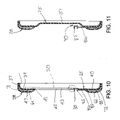
- FIG. 11 is a side cross-sectional view as taken along line 11 - 11 of FIG. 2 .
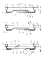
- FIG. 12 is a side cross-sectional view of the cover tile of FIG. 10 mounted to a wall panel frame.
- FIG. 13 is a side cross-sectional view of the cover tile assembly of FIG. 11 mounted to the wall panel frame.
- FIG. 14 illustrates a further cross-sectional view of the cover tile mounted to the panel frame.
- a wall panel system 10 of the invention which comprises a plurality of wall panels 11 joined together in end-to-end relation.
- Each wall panel 11 generally comprises an interior load-bearing wall panel frame 12 ( FIGS. 1 and 14 ), wherein the interior panel frames 12 include a plurality of cover tiles 14 mounted thereto so as to overlie the open interior of the panel frames 12 and provide aesthetic finished surfaces 15 .
- One of the exemplary wall panels 11 may also have a glass-type panel insert 17 mounted thereto which is illustrated in FIG. 1 for illustrative purposes.
- a three-dimensional cover tile 16 of the invention is also provided on a respective wall panel frame 12 which provides additional functionality over and above the planar cover tiles 14 which primarily serve to define the aesthetic exterior surface of the wall panel 11 .
- the three-dimensional cover tile 16 of the invention provides this additional functionality, such as storage and ventilation functions, which functions are incorporated directly into the cover tile 16 rather than through separate, add-on panel components as will be discussed in further detail hereinafter.
- the panel frames 12 as illustrated in FIGS. 12-14 have any conventional construction which typically is defined by a plurality of vertical frame members 18 and horizontal frame members 19 rigidly joined together, such as by welding.
- conventional panel frames 12 have the horizontal frame members 19 located at the top and bottom of the wall panel 11 and also include additional horizontal frame members 19 disposed at intermediate positions such as position 20 in FIGS. 12-14 .
- the three-dimensional cover tile 16 of the invention is readily adaptable to any conventional wall panel frame 12 and may be demountably engaged to the panel frame 12 through any conventional connector arrangement.
- the panel frame 12 defines open interior regions 21 disposed vertically between the horizontal frame members 19 wherein the planar cover tiles 14 or the three-dimensional cover tile(s) 16 are removably engaged with the panel frame 12 so as to overlie and enclose these open frame regions 21 .
- the wall panel system 10 also is configured so as to include additional add-on components such as the illustrated work surface 23 ( FIG. 1 ) or other conventional types of add-on components such as overhead storage units, mounting brackets for accessories, and the like.
- these add-on components such as the work surface 23 include appropriate mounting brackets for engagement with the panel frames 12 so as to rigidly mount such add-on components to the panel frame 12 outwardly of the exposed exterior surfaces 15 of the various cover tiles 14 .
- Such add-on components also may be disposed outwardly of the three-dimensional cover tile 16 where necessary, although due to the added functionality provided by this cover tile 16 , it would be preferred to not position add-on components in overlying relation with the cover tile 16 since such might interfere with the storage and ventilation functions being performed thereby.
- the three-dimensional cover tile 16 is illustrated, wherein the cover tile 16 comprises a back panel 25 which includes a plurality of connectors 26 depicted in phantom outline for connecting the cover tile to the panel frame 12 .
- the cover tile 16 further includes a front panel 28 which is mounted in overlying, facing relation with back panel 25 .
- the interior region 29 of the assembly of the tile panels 25 and 28 comprises a tack board or other insert 30 which may be used for the mounting of messages thereto or if such insert 30 is a whiteboard material, messages may be written thereon.
- the rear panel 25 and front panel 28 are configured so as to be spaced away from each other within this interior region 29 and define a storage pocket 31 in which may be stored various articles 32 , such as a sheet of paper, booklet or other generally rectangular, thin articles.
- a rail 35 is provided which extends horizontally thereacross and forms an additional intermediate storage region which is an extension of the closed pocket 31 .
- This back panel 25 has a generally rectangular shape formed by peripheral edge portion 36 .
- this peripheral edge portion 36 as it extends along the top and bottom of the back panel 25 is defined by top and bottom edge walls or flanges 37 and 38 which extend generally rearwardly and also extend forwardly and curve interiorally.
- the cross section of FIG. 4 extends through a left side portion of this rear panel 25 through a triangular window 42 formed therein.
- This triangular window 42 extends through the thickness of the front wall 41 wherein the insert 30 is then mounted to the back face of the front wall 41 .
- the front face 43 ( FIG. 2 ) of this insert 30 is thereby visible and accessible through the window 42 for the fastening of notes, messages and the like ( 43 A) thereon by fasteners 43 B if such insert 30 is a tackboard.
- the cover tile 16 also provides a messaging function or other indicia supporting function.
- the back portion 25 as seen in FIG. 4 also supports the tile connectors 26 thereon as diagrammatically illustrated in FIG. 4 .
- These connectors 26 may be conventional hooks or resilient catches which releasably engage the cover tile assembly 16 onto the panel frame 12 .
- a notch 45 is provided through the thickness of the back panel 25 near the bottom corner of the window 42 so as to support the leftward end of the rail 35 as will be discussed in further detail hereinafter.
- the face of the front wall 41 also includes elongate strips of a sound-dampening or deadening material 47 and 48 such as a fabric.
- a sound-dampening or deadening material 47 and 48 such as a fabric. The function of the sound-dampening material strips 47 and 48 will be described in further detail relative to the ventilation function which may be performed through this cover tile 16 .
- this cross section is generally taken through the center portion of the back panel 25 and further illustrates the shape of the upper and lower front wall portions 39 and 40 which terminate along the perimetral edge of the back panel 25 through the edge walls 37 and 38 .
- the front wall 41 bends rearwardly away from the front face walls 39 and 40 to define a depressed cavity portion 50 .
- This cavity portion 50 is primarily defined by a cavity wall 51 which has the shape generally illustrated in FIG. 3 and is bounded by the cavity edge 52 which extends about the periphery of the cavity wall 51 .
- the front panel 28 comprises perimetral side edges 55 - 58 which generally extend rearwardly and terminate at the rear edge 59 .
- the front panel 26 further includes a front wall 60 which is defined by upper and lower wall portions 61 and 62 , left side portion 63 and right side portion 64 . It is noted that the upper wall portion 61 is provided with two elongate horizontal rows of staggered openings 65 while the bottom wall portion 62 includes generally S-shaped openings 66 extending across the width of the front panel 26 . Additionally, the front wall 60 is formed with a window 70 which opens through the thickness of the front panel 28 .
- both the rear and front panels 25 and 28 are formed of a molded plastic which is readily shapable and moldable to provide the desired three-dimensional configuration described above relative to FIGS. 3-9 .
- these back and front panels 25 and 28 are configured to fit one over the other with the front panel 28 fitting over the back panel 25 wherein the respective side edges fit one over the other in adjacent abutting relation as best illustrated in FIGS. 6 and 12 - 14 .
- the front panel 28 has the front wall portions 61 and 62 spaced forwardly of the opposing back wall portions 39 and 40 of the back panel 25 .
- These opposing wall portions 39 and 61 as seen in FIG. 6 define a horizontal passage 71 which extends horizontally across the width of the cover tile 16 along the length of the pattern of the openings 65 . This space 71 is also provided even with the presence of the sound-dampening fabric strip 47 as seen in FIG. 6 .
- the bottom wall portions 40 and 62 make a similar bottom passageway or channel 72 also extending across the width of the cover tile 16 along the length of the pattern of openings 66 .
- the three-dimensional cover tile 16 is provided with horizontal passageways with groups or patterns of exit openings 65 and 66 that open forwardly towards a work station area.
- these passageways 71 and 72 may be used for ventilation where desired to allow the passage of an air flow through such passages 71 and 72 and allow for air to be blown through the patterns of openings 65 and 66 .
- the back panel 26 may be provided with inlet passages or ports such as ports 75 and 76 which are diagrammatically illustrated in a center position in the panel wall 41 .
- Such ports 75 and 76 may be rectangular ports extending entirely through the panel wall 41 wherein, in such instance, the center portions of the strips 77 would be removed in the region of these inlet ports 75 and 76 .
- ventilation air may be passed through these inlet ports 75 and 76 from the hollow frame interior 21 wherein the air is generally illustrated flowing into this region by reference arrows 80 of FIG. 6 wherein such air flow would pass through the passages 71 and 72 and be allowed to exit through the wall portions 61 and 62 as indicated by reference arrows 81 in FIG. 6 .
- the patterns of the openings 65 and 66 essentially define exit ports or passages for the ventilation flow. It will be understood that the shapes and patterns as well as the sizes of these openings 65 and 66 may be readily varied depending upon the total air flow desired and the overall design of the heating and ventilation system to which the passages 71 and 72 may be connected. Because of these patterns of openings 65 and 66 , the sound-dampening fabric strips 47 and 48 may be provided.
- the ports 75 and 76 may also be eliminated or omitted while the patterns of openings 65 and 66 are still provided.
- these panel openings 65 and 66 may perform the additional function of dampening sound since it allows for the passage of sound through these openings 65 and 66 wherein the sound waves are then dampened or reduced by striking the dampening strips 47 and 48 .
- the assembly therein is illustrated with the tackboard insert 30 attached to the inside face of the front panel wall 41 of the back panel 25 .
- This insert 30 thereby has the front face 43 thereof facing forwardly that is accessible through the window 42 .
- this compartment rail 35 comprises a top stiffener rail 85 which extends along the upper length thereof as seen in FIGS. 2 and 10 and also has a wire mesh portion 86 extending downwardly from the extruded metal stiffener rail 85 .
- the leftward end of the stiffener rail 87 is illustrated in FIG. 2 as projecting leftwardly and rearwardly through the panel wall 41 of the back panel 26 as also illustrated in FIG. 10 .
- This left rail end 87 is accommodated by the notch 45 ( FIG. 3 ) formed in the left end region of the back panel 25 so as to rigidly secure the stiffener rail 85 in place by suitable fasteners or preferably, adhesives which are adhered to the tile panels 25 and 26 .
- the bottom edge 88 of the wire mesh 86 is also secured or affixed by suitable adhesives between the opposing surfaces of the front panel 25 and rear panel 26 as seen in FIG. 10 .
- FIG. 11 illustrates that a horizontally elongate, relatively shallow storage compartment 90 is thereby formed behind the rail 35 and the opposing compartment wall 70 that is formed in the compartment wall.
- FIG. 13 the cover tile 16 is mounted onto the panel frame 12 wherein FIG. 13 illustrates an additional article 91 which is supported within this additional storage compartment 90 .
- the storage compartment 90 opens upwardly and is able to accommodate paper-size materials or smaller items such as floppy disks, booklets and the like.
- the rightward end of the compartment rail 35 is identified by reference numeral 93 wherein this rail end 93 is fixedly adhered to the inside face of the right wall portion 64 of the front panel 28 . More particularly as seen in FIG. 14 , the front wall portion 64 as well as the interior compartment wall 51 define the sideward opening storage pocket 31 previously referenced in FIG. 2 , which compartment 31 is configured to store various articles thereon such as article 32 ( FIGS. 2 and 14 ).
- the insert 30 may also be used to support additional components such as an electrical receptacle 100 which is supplied with electricity by cabling 101 that extends into the frame interior 21 .
- This receptacle 100 may include a face plate 102 that mounts to insert panel 30 as diagrammatically illustrated in the front view of FIG. 2 .
- the cover tile 16 may also have an electrical functionality and this receptacle 100 not only may be a power supply, but also could be a data or telecommunications receptacle of a generally conventional configuration.
- the cover tile 16 may be readily designed as a component of a wall panel system 10 in the design phase.
- the cover tile 16 may have the same general size and shape and connectors as an existing planar cover tile 14 such that if desired, the three-dimensional cover tile 16 may be inserted in place of an existing planar cover tile.
Abstract
A wall panel system having a wall panel frame and three-dimensional cover tiles is provided. Such cover tiles overlie an open interior frame region and demountably engage the panel frame. These cover tiles are provided with a relatively shallow thickness but are formed with various formations including storage pockets and the like which allow office items and other articles to be stored directly in the cover tile as opposed to add-on components which mount over the face of a conventional planar cover tile.
Description
- The invention relates to a wall panel system having one or more three-dimensional cover tiles, and in particular, to a cover tile for such a wall panel system which serves to not only cover the interior of a wall panel but also serve additional functions such as storage or ventilation.
- In conventional office spaces, larger spaces are subdivided by known space-dividing wall panel systems. Such wall panel systems comprise an interior panel frame defining open areas within the frame, and a plurality of substantially flat or planar cover tiles which are removably mounted onto the frame so as to overlie and cover the open frame interior.
- Primarily, such conventional planar cover tiles are substantially flat in the vertical dimension and have outward facing exterior surfaces which define the finished aesthetic appearance of the wall panel. The finished exterior surface of the cover tile typically is flat or at least has an exposed surface texture, such as fabric, which serves an aesthetic function.
- In known wall panel systems, such systems further include various add-on accessories and structures which mount to the panel frame separate from the cover tile and are disposed outwardly of the cover tile surface to provide for storage in office areas or workstations defined by the wall panel system. For example, such add-on accessories may include overhead storage units, shelving, and racks on which additional shelves and smaller accessories are hung. Such systems require components separate from the cover tiles and result in additional complexity for the wall panel system since it requires a mounting arrangement not only for the cover tiles but also for the add-on accessories. Further, such accessories project outwardly of the face of the cover tile surfaces a noticeable distance which may be undesirable in some environments and specific applications.
- It is an object of the invention to provide an improved cover tile which not only defines an aesthetic appearance for the wall panel, but also provides for storage capacity and other functions.
- The invention thereby relates to a wall panel system comprising a basic wall panel frame defining an open interior therein. The invention further includes one or more three-dimensional cover tiles which each extend laterally across the width of its respective wall panel frame and extend a pre-defined vertical distance so as to overlie and enclose at least a portion, if not all, of an open interior region of the wall panel frame.
- In particular, these three-dimensional cover tiles are formed so as to have a back portion which includes tile connectors thereon that are removably engagable with the wall panel frame. The cover tiles further include front portions which project outwardly a necessary distance away from the back portion and are configured to include storage formations therein such as pockets and the like.
- Sections of the front and back portions of the cover tile have exposed exterior surfaces which define the aesthetic face of the wall panel frame when provided in combination with other three-dimensional cover tiles and/or planar cover tiles. Hence, these three-dimensional cover tiles define a storage capacity and/or other different functional capacities in the cover tile since the cover tile is enlarged in three dimensions, not only laterally and vertically, but also outwardly away from the panel frame. This additional storage capacity is provided in a limited outward depth so that the thickness of the cover tile is still relatively shallow and provides the desired storage capacity in a smaller outward distance as compared to conventional add-on components which mount over the face of a conventional planar cover tile.
- Other objects and purposes of the invention, and variations thereof, will be apparent upon reading the following specification and inspecting the accompanying drawings.
-
FIG. 1 is a perspective view of a wall panel arrangement have a three-dimensional cover tile mounted thereto. -
FIG. 2 is a front elevational view of an assembled three-dimensional cover tile. -
FIG. 3 is a front view of a back panel of the cover tile assembly. -
FIG. 4 is a side cross-sectional view of the back panel as taken along line 4-4 ofFIG. 3 . -
FIG. 5 is a side cross-sectional view as taken along line 5-5 ofFIG. 3 . -
FIG. 6 is a partial side cross-sectional view of the tile assembly as taken along line 6-6 ofFIG. 2 . -
FIG. 7 is a front view of a front panel of the cover tile assembly. -
FIG. 8 is a bottom cross-sectional view of the front panel as taken along line 8-8 ofFIG. 7 . -
FIG. 9 is a side cross-sectional view of the front panel as taken along line 9-9 ofFIG. 7 . -
FIG. 10 is a side cross-sectional view of the cover tile assembly as taken along line 10-10 ofFIG. 2 . -
FIG. 11 is a side cross-sectional view as taken along line 11-11 ofFIG. 2 . -
FIG. 12 is a side cross-sectional view of the cover tile ofFIG. 10 mounted to a wall panel frame. -
FIG. 13 is a side cross-sectional view of the cover tile assembly ofFIG. 11 mounted to the wall panel frame. -
FIG. 14 illustrates a further cross-sectional view of the cover tile mounted to the panel frame. - Certain terminology will be used in the following description for convenience and reference only, and will not be limiting. For example, the words “upwardly”, “downwardly”, “rightwardly” and “leftwardly” will refer to directions in the drawings to which reference is made. The words “inwardly” and “outwardly” will refer to directions toward and away from, respectively, the geometric center of the arrangement and designated parts thereof. Said terminology will include the words specifically mentioned, derivatives thereof, and words of similar import.
- Referring to
FIG. 1 , awall panel system 10 of the invention is illustrated which comprises a plurality ofwall panels 11 joined together in end-to-end relation. Eachwall panel 11 generally comprises an interior load-bearing wall panel frame 12 (FIGS. 1 and 14 ), wherein theinterior panel frames 12 include a plurality ofcover tiles 14 mounted thereto so as to overlie the open interior of thepanel frames 12 and provide aesthetic finishedsurfaces 15. One of theexemplary wall panels 11 may also have a glass-type panel insert 17 mounted thereto which is illustrated inFIG. 1 for illustrative purposes. - Additionally, a three-
dimensional cover tile 16 of the invention is also provided on a respectivewall panel frame 12 which provides additional functionality over and above theplanar cover tiles 14 which primarily serve to define the aesthetic exterior surface of thewall panel 11. The three-dimensional cover tile 16 of the invention provides this additional functionality, such as storage and ventilation functions, which functions are incorporated directly into thecover tile 16 rather than through separate, add-on panel components as will be discussed in further detail hereinafter. - More particularly as to the
wall panel system 10, thepanel frames 12 as illustrated inFIGS. 12-14 have any conventional construction which typically is defined by a plurality ofvertical frame members 18 andhorizontal frame members 19 rigidly joined together, such as by welding. Generally,conventional panel frames 12 have thehorizontal frame members 19 located at the top and bottom of thewall panel 11 and also include additionalhorizontal frame members 19 disposed at intermediate positions such asposition 20 inFIGS. 12-14 . It is noted that the three-dimensional cover tile 16 of the invention is readily adaptable to any conventionalwall panel frame 12 and may be demountably engaged to thepanel frame 12 through any conventional connector arrangement. Generally, thepanel frame 12 defines openinterior regions 21 disposed vertically between thehorizontal frame members 19 wherein theplanar cover tiles 14 or the three-dimensional cover tile(s) 16 are removably engaged with thepanel frame 12 so as to overlie and enclose theseopen frame regions 21. - The
wall panel system 10 also is configured so as to include additional add-on components such as the illustrated work surface 23 (FIG. 1 ) or other conventional types of add-on components such as overhead storage units, mounting brackets for accessories, and the like. Generally, these add-on components such as thework surface 23 include appropriate mounting brackets for engagement with thepanel frames 12 so as to rigidly mount such add-on components to thepanel frame 12 outwardly of the exposedexterior surfaces 15 of thevarious cover tiles 14. Such add-on components also may be disposed outwardly of the three-dimensional cover tile 16 where necessary, although due to the added functionality provided by thiscover tile 16, it would be preferred to not position add-on components in overlying relation with thecover tile 16 since such might interfere with the storage and ventilation functions being performed thereby. - Referring more particularly to
FIG. 2 , the three-dimensional cover tile 16 is illustrated, wherein thecover tile 16 comprises aback panel 25 which includes a plurality ofconnectors 26 depicted in phantom outline for connecting the cover tile to thepanel frame 12. Thecover tile 16 further includes afront panel 28 which is mounted in overlying, facing relation withback panel 25. - The
interior region 29 of the assembly of thetile panels other insert 30 which may be used for the mounting of messages thereto or ifsuch insert 30 is a whiteboard material, messages may be written thereon. Additionally, therear panel 25 andfront panel 28 are configured so as to be spaced away from each other within thisinterior region 29 and define astorage pocket 31 in which may be storedvarious articles 32, such as a sheet of paper, booklet or other generally rectangular, thin articles. In the area located laterally between thestorage pocket 31 and theinsert 30, arail 35 is provided which extends horizontally thereacross and forms an additional intermediate storage region which is an extension of the closedpocket 31. - More particularly as to the individual components, and the final assembly thereof, the following discussion first turns to the configuration of the back panel or back portion 25 (
FIGS. 3-5 ). Thisback panel 25 has a generally rectangular shape formed byperipheral edge portion 36. As to the cross section ofFIG. 4 , thisperipheral edge portion 36 as it extends along the top and bottom of theback panel 25 is defined by top and bottom edge walls orflanges - Towards the left end of the
cover tile 16, the cross section ofFIG. 4 extends through a left side portion of thisrear panel 25 through atriangular window 42 formed therein. Thistriangular window 42 extends through the thickness of thefront wall 41 wherein theinsert 30 is then mounted to the back face of thefront wall 41. As such, the front face 43 (FIG. 2 ) of thisinsert 30 is thereby visible and accessible through thewindow 42 for the fastening of notes, messages and the like (43A) thereon by fasteners 43B ifsuch insert 30 is a tackboard. Thus, thecover tile 16 also provides a messaging function or other indicia supporting function. - Generally, the
back portion 25 as seen inFIG. 4 also supports thetile connectors 26 thereon as diagrammatically illustrated inFIG. 4 . Theseconnectors 26 may be conventional hooks or resilient catches which releasably engage thecover tile assembly 16 onto thepanel frame 12. - Additionally as to the cross-sectional view of
FIG. 4 , anotch 45 is provided through the thickness of theback panel 25 near the bottom corner of thewindow 42 so as to support the leftward end of therail 35 as will be discussed in further detail hereinafter. - As will also be described in further detail, the face of the
front wall 41 also includes elongate strips of a sound-dampening or deadeningmaterial cover tile 16. - Referring to the cross-sectional view of
FIG. 5 , this cross section is generally taken through the center portion of theback panel 25 and further illustrates the shape of the upper and lowerfront wall portions back panel 25 through theedge walls center region 29, thefront wall 41 bends rearwardly away from thefront face walls depressed cavity portion 50. Thiscavity portion 50 is primarily defined by acavity wall 51 which has the shape generally illustrated inFIG. 3 and is bounded by thecavity edge 52 which extends about the periphery of thecavity wall 51. - Referring more particularly as to
FIGS. 6-9 , thefront panel 28 is illustrated. Thisfront panel 28 comprises perimetral side edges 55-58 which generally extend rearwardly and terminate at therear edge 59. Thefront panel 26 further includes afront wall 60 which is defined by upper andlower wall portions left side portion 63 andright side portion 64. It is noted that theupper wall portion 61 is provided with two elongate horizontal rows ofstaggered openings 65 while thebottom wall portion 62 includes generally S-shapedopenings 66 extending across the width of thefront panel 26. Additionally, thefront wall 60 is formed with awindow 70 which opens through the thickness of thefront panel 28. - Preferably, both the rear and
front panels FIGS. 3-9 . Generally, these back andfront panels front panel 28 fitting over theback panel 25 wherein the respective side edges fit one over the other in adjacent abutting relation as best illustrated in FIGS. 6 and 12-14. When fitted together, thefront panel 28 has thefront wall portions wall portions back panel 25. These opposingwall portions FIG. 6 define ahorizontal passage 71 which extends horizontally across the width of thecover tile 16 along the length of the pattern of theopenings 65. Thisspace 71 is also provided even with the presence of the sound-dampeningfabric strip 47 as seen inFIG. 6 . - Referring to
FIG. 10 , thebottom wall portions channel 72 also extending across the width of thecover tile 16 along the length of the pattern ofopenings 66. As such, the three-dimensional cover tile 16 is provided with horizontal passageways with groups or patterns ofexit openings - In one embodiment, these
passageways such passages openings cover tile 16, theback panel 26 may be provided with inlet passages or ports such as ports 75 and 76 which are diagrammatically illustrated in a center position in thepanel wall 41. Such ports 75 and 76 may be rectangular ports extending entirely through thepanel wall 41 wherein, in such instance, the center portions of the strips 77 would be removed in the region of these inlet ports 75 and 76. As such, ventilation air may be passed through these inlet ports 75 and 76 from the hollow frame interior 21 wherein the air is generally illustrated flowing into this region byreference arrows 80 ofFIG. 6 wherein such air flow would pass through thepassages wall portions reference arrows 81 inFIG. 6 . The patterns of theopenings openings passages openings - Alternatively, the ports 75 and 76 may also be eliminated or omitted while the patterns of
openings panel openings openings strips - Referring more particularly to
FIG. 10 , the assembly therein is illustrated with thetackboard insert 30 attached to the inside face of thefront panel wall 41 of theback panel 25. Thisinsert 30 thereby has thefront face 43 thereof facing forwardly that is accessible through thewindow 42. - With respect to the
compartment rail 35, thiscompartment rail 35 comprises atop stiffener rail 85 which extends along the upper length thereof as seen inFIGS. 2 and 10 and also has awire mesh portion 86 extending downwardly from the extrudedmetal stiffener rail 85. The leftward end of thestiffener rail 87 is illustrated inFIG. 2 as projecting leftwardly and rearwardly through thepanel wall 41 of theback panel 26 as also illustrated inFIG. 10 . This leftrail end 87 is accommodated by the notch 45 (FIG. 3 ) formed in the left end region of theback panel 25 so as to rigidly secure thestiffener rail 85 in place by suitable fasteners or preferably, adhesives which are adhered to thetile panels bottom edge 88 of thewire mesh 86 is also secured or affixed by suitable adhesives between the opposing surfaces of thefront panel 25 andrear panel 26 as seen inFIG. 10 . - Moving rightwardly across the
cover tile 16,FIG. 11 illustrates that a horizontally elongate, relativelyshallow storage compartment 90 is thereby formed behind therail 35 and the opposingcompartment wall 70 that is formed in the compartment wall. - Referring to
FIG. 13 , thecover tile 16 is mounted onto thepanel frame 12 whereinFIG. 13 illustrates anadditional article 91 which is supported within thisadditional storage compartment 90. Thestorage compartment 90 opens upwardly and is able to accommodate paper-size materials or smaller items such as floppy disks, booklets and the like. - Turning next to the cross section of
FIG. 14 , the rightward end of thecompartment rail 35 is identified byreference numeral 93 wherein thisrail end 93 is fixedly adhered to the inside face of theright wall portion 64 of thefront panel 28. More particularly as seen inFIG. 14 , thefront wall portion 64 as well as theinterior compartment wall 51 define the sidewardopening storage pocket 31 previously referenced inFIG. 2 , whichcompartment 31 is configured to store various articles thereon such as article 32 (FIGS. 2 and 14 ). - Referring additionally to
FIG. 12 , it is noted that theinsert 30 may also be used to support additional components such as anelectrical receptacle 100 which is supplied with electricity by cabling 101 that extends into theframe interior 21. Thisreceptacle 100 may include aface plate 102 that mounts to insertpanel 30 as diagrammatically illustrated in the front view ofFIG. 2 . Thus, thecover tile 16 may also have an electrical functionality and thisreceptacle 100 not only may be a power supply, but also could be a data or telecommunications receptacle of a generally conventional configuration. - With the foregoing arrangement, the
cover tile 16 may be readily designed as a component of awall panel system 10 in the design phase. Alternatively, thecover tile 16 may have the same general size and shape and connectors as an existingplanar cover tile 14 such that if desired, the three-dimensional cover tile 16 may be inserted in place of an existing planar cover tile. - Although particular preferred embodiments of the invention have been disclosed in detail for illustrative purposes, it will be recognized that variations or modifications of the disclosed apparatus, including the rearrangement of parts, lie within the scope of the present invention.
Claims (20)
1. A cover tile for a wall panel comprising:
a back panel having edge portions and an interior portion disposed laterally between said edge portions, said back panel being a shape which is enlarged laterally and vertically so as to overlie a portion of a wall panel frame; and
a front panel in a shape corresponding to the back panel and being adapted to fit over said back panel in facing relation to define a front-back panel assembly, said front panel comprising edge portions which extend about and are disposed closely adjacent to said edge portions of said back panel for securing said front and back panel together, said front panel further including an interior portion disposed laterally between said edge portions of said front panel, wherein said interior portions of said front and back panel define opposing compartment walls to define a storage compartment which is open from an exterior of said cover tile to permit the storage and insertion of articles within said storage compartment and to permit the storage of said articles on said cover tile.
2. The cover tile according to claim 1 , wherein said cover tile includes an elongate rail member extending laterally across a portion of said cover tile and being joined to said front-back panel assembly, said rail member defining a front wall of a further storage compartment disposed forwardly of an opposing wall of said back panel to define an additional storage compartment area which is accessible from an exterior forward side of said cover tile.
3. The cover tile according to claim 1 , wherein said back panel is formed with an opening in which is mounted an insert that allows for fastening of additional articles on said cover tile.
4. The cover tile according to claim 3 , wherein said insert comprises a tack-board material and said articles comprise piercable articles which may be hung on said insert by fasteners.
5. The cover tile according to claim 3 , wherein an electrical component is mounted to said insert and has an exposed portion accessible through a front face of said insert from an exterior of said cover tile.
6. The cover tile according to claim 5 , wherein said electrical component is an electrical receptacle that is connectable to at least one of power cabling and data cabling.
7. The cover tile according to claim 1 , wherein said edge portions of said back panel and said front panel are spaced apart from each other to define interior channels extending widthwise across said cover tile.
8. The cover tile according to claim 7 , wherein said front-back panel assembly includes sound-dampening inserts extending interiorally of said channels, said edge portion of said front panel further including patterns of openings which open into said channels wherein said sound-dampening inserts serve to dampen sound waves passing through said openings.
9. The tile according to claim 8 , wherein said edge portions comprise ventilation passages wherein driven air flows through said passages and exits through said groups of openings.
10. A wall panel assembly comprising:
an upright wall panel frame; and
a cover tile assembly comprising a back panel having edge portions and an interior portion disposed laterally between said edge portions, said back panel being a shape which is enlarged laterally and vertically so as to overlie a portion of a wall panel frame; and
a front panel in a shape corresponding to the back panel and being adapted to fit over said back panel in facing relation to define a front-back panel assembly, said front panel comprising edge portions which extend about and are disposed closely adjacent to said edge portions of said back panel for securing said front and back panel together, said front panel further including an interior portion disposed between said edge portions of said front panel, wherein said interior portions of said front and back panel define opposing compartment walls to define a storage compartment which is open from an exterior of said cover tile to permit the storage and insertion of articles within said storage compartment and to permit the storage of said articles on said cover tile.
11. The wall panel assembly according to claim 10 , wherein said cover tile includes an elongate rail member extending laterally across a portion of said cover tile and being joined to said front-back panel assembly, said rail member defining a front wall of a further storage compartment disposed forwardly of an opposing wall of said back panel to define an additional storage compartment area which is accessible from an exterior, forward side of said cover tile.
12. The wall panel assembly according to claim 10 , wherein said back panel is formed with an opening in which is mounted an insert that allows for fastening of additional articles on said cover tile.
13. The wall panel assembly according to claim 10 , wherein said wall panel frame comprises horizontal and vertical frame members which define open interior regions of said panel frame.
14. The wall panel assembly according to claim 13 , wherein an electrical component is mounted on said insert and has a front receptacle portion which is accessible through a front of said insert from an exterior of said cover tile, said receptacle portion being connected to cabling which extends into said frame interior.
15. The wall panel assembly according to claim 10 , wherein said edge portions of said front and back panels define channels extending through the interior of said front and back panel assembly and have groups of openings which open through said edge portions of said front panel openings between said passages and an exterior of said cover tile.
16. The wall panel assembly according to claim 15 , wherein said passages include sound-dampening strips disposed on interior faces of said passages which dampen sound waves passing through said openings.
17. A wall panel assembly comprising:
a wall panel frame; and
a cover tile assembly comprising a back panel having edge portions and an interior portion disposed laterally between said edge portions, said back panel being a shape which is enlarged laterally and vertically so as to overlie a portion of a wall panel frame;
a front panel in a shape corresponding to the back panel and being adapted to fit over said back panel in facing relation to define a front-back panel assembly, said front panel comprising edge portions which extend about and are disposed closely adjacent to said edge portions of said back panel for securing said front and back panel together, said front panel further including an interior portion disposed between said edge portions of said front panel, wherein said interior portions of said front and back panel define opposing compartment walls to define a storage compartment which is open from an exterior of said cover tile to permit the storage and insertion of articles within said storage compartment and to permit the storage of said articles on said cover tile; and
said edge portions of said front and back panels including passages disposed interiorally of said front-back panel assembly and having groups of openings through said edge portions of said front panel to define passages between said interior passages and an exterior of said cover tile.
18. The wall panel assembly according to claim 17 , wherein passages define ventilation passages for the passage of ventilation air therethrough.
19. The wall panel assembly according to claim 18 , wherein said passages include sound-dampening materials which dampen sound waves within said passages.
20. The wall panel assembly according to claim 17 , wherein said back panel includes an insert mounted thereon having a front face which is accessible through a window in said front-back panel assembly, said front face of said insert being configured to permit one of the mounting of separate articles to said front face and a port for an electrical component mounted on said insert wherein cabling extends rearwardly into open interior regions of said panel frame.
Priority Applications (1)
| Application Number | Priority Date | Filing Date | Title |
|---|---|---|---|
| US11/590,618 US20080098680A1 (en) | 2006-10-31 | 2006-10-31 | Three-dimensional cover tile |
Applications Claiming Priority (1)
| Application Number | Priority Date | Filing Date | Title |
|---|---|---|---|
| US11/590,618 US20080098680A1 (en) | 2006-10-31 | 2006-10-31 | Three-dimensional cover tile |
Publications (1)
| Publication Number | Publication Date |
|---|---|
| US20080098680A1 true US20080098680A1 (en) | 2008-05-01 |
Family
ID=39328479
Family Applications (1)
| Application Number | Title | Priority Date | Filing Date |
|---|---|---|---|
| US11/590,618 Abandoned US20080098680A1 (en) | 2006-10-31 | 2006-10-31 | Three-dimensional cover tile |
Country Status (1)
| Country | Link |
|---|---|
| US (1) | US20080098680A1 (en) |
Cited By (2)
| Publication number | Priority date | Publication date | Assignee | Title |
|---|---|---|---|---|
| US9206827B2 (en) | 2012-11-20 | 2015-12-08 | Avery Dennison Corporation | Wall mount organization system |
| US10221529B1 (en) * | 2018-03-13 | 2019-03-05 | Mute Wall Systems, Inc. | Wall panels, barrier wall constructed from same, and methods of making both |
Citations (25)
| Publication number | Priority date | Publication date | Assignee | Title |
|---|---|---|---|---|
| US2272829A (en) * | 1938-09-26 | 1942-02-10 | Hauserman Co E F | Partition |
| US3497079A (en) * | 1967-11-21 | 1970-02-24 | Chester Kulwiec | Framing and mounting means for perforated panels |
| US3659355A (en) * | 1970-11-02 | 1972-05-02 | Adelard L Aubin Jr | Wall mounted combination chalkboard, projector screen and information display apparatus |
| US3858727A (en) * | 1972-12-01 | 1975-01-07 | Leo Levko | Bulletin board assembly |
| US4876835A (en) * | 1984-09-10 | 1989-10-31 | Herman Miller, Inc. | Work space management system |
| US4942805A (en) * | 1989-02-02 | 1990-07-24 | Teknion Furniture Systems Inc. | Ventilated panel |
| US5352033A (en) * | 1992-03-27 | 1994-10-04 | Fisher-Rosemount Systems, Inc. | Operator work station having a monitor support assembly |
| US5626404A (en) * | 1988-06-10 | 1997-05-06 | Herman Miller, Inc. | Work space management system and cabinet therefor |
| US5743054A (en) * | 1994-12-30 | 1998-04-28 | Steelcase Inc. | Modular utilities cover |
| US5943834A (en) * | 1996-12-17 | 1999-08-31 | Steelcase Inc. | Partition construction |
| US5980279A (en) * | 1997-09-25 | 1999-11-09 | Nienkamper Furniture & Accessories Inc. | Recessed electrical receptacle and work surface |
| US6073399A (en) * | 1998-01-28 | 2000-06-13 | Steelcase Development Inc. | Post and beam supported slatwall |
| US6158179A (en) * | 1998-03-10 | 2000-12-12 | Steelcase Development Inc. | Overhead structures for wall system |
| US6201687B1 (en) * | 1998-10-09 | 2001-03-13 | American Access Technologies, Inc. | Modular furniture wall system and method for telecommunications equipment and wire management in an open office architecture |
| US6253509B1 (en) * | 1999-08-13 | 2001-07-03 | Teknion Furniture Systems Limited | Workspace partition system |
| US6349516B1 (en) * | 1999-06-04 | 2002-02-26 | Haworth, Inc. | Frame arrangement for a wall panel system |
| US20020029529A1 (en) * | 1998-04-15 | 2002-03-14 | Waalkes Michael L. | Cover panel brace for partitions systems |
| US6397534B1 (en) * | 2000-06-12 | 2002-06-04 | Steelcase Development Corporation | Cover member lock for partition panels |
| US6446396B1 (en) * | 1999-06-04 | 2002-09-10 | Teknion Furniture Systems Limited | Wall system |
| US6463701B1 (en) * | 1998-10-30 | 2002-10-15 | Steelcase Development Corporation | Work environment |
| US20030154673A1 (en) * | 2002-02-15 | 2003-08-21 | Macgregor Bruce G. | Partition panel with modular appliance mounting arrangement |
| US6612077B2 (en) * | 2001-06-15 | 2003-09-02 | Inscape Corporation | Mounting arrangement for whiteboard |
| US6625935B1 (en) * | 2000-10-20 | 2003-09-30 | Steelcase Development Corporation | Partition system with worktools |
| US6711871B2 (en) * | 2000-05-03 | 2004-03-30 | Herman Miller, Inc. | Wall panel with off-module components |
| US20040093805A1 (en) * | 2002-06-06 | 2004-05-20 | Underwood Robert A. | Partition system |
-
2006
- 2006-10-31 US US11/590,618 patent/US20080098680A1/en not_active Abandoned
Patent Citations (27)
| Publication number | Priority date | Publication date | Assignee | Title |
|---|---|---|---|---|
| US2272829A (en) * | 1938-09-26 | 1942-02-10 | Hauserman Co E F | Partition |
| US3497079A (en) * | 1967-11-21 | 1970-02-24 | Chester Kulwiec | Framing and mounting means for perforated panels |
| US3659355A (en) * | 1970-11-02 | 1972-05-02 | Adelard L Aubin Jr | Wall mounted combination chalkboard, projector screen and information display apparatus |
| US3858727A (en) * | 1972-12-01 | 1975-01-07 | Leo Levko | Bulletin board assembly |
| US4876835A (en) * | 1984-09-10 | 1989-10-31 | Herman Miller, Inc. | Work space management system |
| US4876835B1 (en) * | 1984-09-10 | 1992-06-30 | Miller Herman Inc | |
| US5626404A (en) * | 1988-06-10 | 1997-05-06 | Herman Miller, Inc. | Work space management system and cabinet therefor |
| US4942805A (en) * | 1989-02-02 | 1990-07-24 | Teknion Furniture Systems Inc. | Ventilated panel |
| US5352033A (en) * | 1992-03-27 | 1994-10-04 | Fisher-Rosemount Systems, Inc. | Operator work station having a monitor support assembly |
| US5743054A (en) * | 1994-12-30 | 1998-04-28 | Steelcase Inc. | Modular utilities cover |
| US5809708A (en) * | 1994-12-30 | 1998-09-22 | Steelcase Inc. | Integrated prefabricated furniture system for fitting-out open plan building space |
| US5943834A (en) * | 1996-12-17 | 1999-08-31 | Steelcase Inc. | Partition construction |
| US5980279A (en) * | 1997-09-25 | 1999-11-09 | Nienkamper Furniture & Accessories Inc. | Recessed electrical receptacle and work surface |
| US6073399A (en) * | 1998-01-28 | 2000-06-13 | Steelcase Development Inc. | Post and beam supported slatwall |
| US6158179A (en) * | 1998-03-10 | 2000-12-12 | Steelcase Development Inc. | Overhead structures for wall system |
| US20020029529A1 (en) * | 1998-04-15 | 2002-03-14 | Waalkes Michael L. | Cover panel brace for partitions systems |
| US6201687B1 (en) * | 1998-10-09 | 2001-03-13 | American Access Technologies, Inc. | Modular furniture wall system and method for telecommunications equipment and wire management in an open office architecture |
| US6463701B1 (en) * | 1998-10-30 | 2002-10-15 | Steelcase Development Corporation | Work environment |
| US6349516B1 (en) * | 1999-06-04 | 2002-02-26 | Haworth, Inc. | Frame arrangement for a wall panel system |
| US6446396B1 (en) * | 1999-06-04 | 2002-09-10 | Teknion Furniture Systems Limited | Wall system |
| US6253509B1 (en) * | 1999-08-13 | 2001-07-03 | Teknion Furniture Systems Limited | Workspace partition system |
| US6711871B2 (en) * | 2000-05-03 | 2004-03-30 | Herman Miller, Inc. | Wall panel with off-module components |
| US6397534B1 (en) * | 2000-06-12 | 2002-06-04 | Steelcase Development Corporation | Cover member lock for partition panels |
| US6625935B1 (en) * | 2000-10-20 | 2003-09-30 | Steelcase Development Corporation | Partition system with worktools |
| US6612077B2 (en) * | 2001-06-15 | 2003-09-02 | Inscape Corporation | Mounting arrangement for whiteboard |
| US20030154673A1 (en) * | 2002-02-15 | 2003-08-21 | Macgregor Bruce G. | Partition panel with modular appliance mounting arrangement |
| US20040093805A1 (en) * | 2002-06-06 | 2004-05-20 | Underwood Robert A. | Partition system |
Cited By (3)
| Publication number | Priority date | Publication date | Assignee | Title |
|---|---|---|---|---|
| US9206827B2 (en) | 2012-11-20 | 2015-12-08 | Avery Dennison Corporation | Wall mount organization system |
| US10231556B2 (en) | 2012-11-20 | 2019-03-19 | Ccl Label, Inc. | Wall mount organization system |
| US10221529B1 (en) * | 2018-03-13 | 2019-03-05 | Mute Wall Systems, Inc. | Wall panels, barrier wall constructed from same, and methods of making both |
Similar Documents
| Publication | Publication Date | Title |
|---|---|---|
| US5038539A (en) | Work space management system | |
| US5746034A (en) | Partition system | |
| US5172504A (en) | Front-mount grid display having trim strips and hook and loop | |
| US6135583A (en) | Storage unit | |
| US5941026A (en) | Slatwall display system | |
| CA2424873C (en) | Straddle bin | |
| US3892189A (en) | Modular shelf construction | |
| US4932538A (en) | Fixture support wall panel | |
| EP0571229A1 (en) | Panel system | |
| US6913164B2 (en) | Adjustable drawer organizer | |
| US20080297015A1 (en) | Storage unit back stop and method | |
| ES2670468T3 (en) | Decorative panels set | |
| US5906079A (en) | Partition system with attached markerboard | |
| US20170020286A1 (en) | Shelf Cover System Configured To Releasably Attach To Wire Frame Shelves | |
| US6256941B1 (en) | Pad for panel | |
| US4577444A (en) | Changeable wall panel structure | |
| US5520234A (en) | Window top decorating assembly | |
| US20080098680A1 (en) | Three-dimensional cover tile | |
| JPH0552203B2 (en) | ||
| US20170238706A1 (en) | Dual-Sided Storage Bin | |
| US4119287A (en) | Supports for movable partitions | |
| US6010015A (en) | Decorative compact disk rack | |
| USD494384S1 (en) | Display unit for wrapping paper and single cartridge adhesive tape using linear panel back | |
| JPH03140539A (en) | Work space control system | |
| JP4857964B2 (en) | Shelf board support structure |
Legal Events
| Date | Code | Title | Description |
|---|---|---|---|
| AS | Assignment |
Owner name: HAWORTH, INC., MICHIGAN Free format text: ASSIGNMENT OF ASSIGNORS INTEREST;ASSIGNORS:MCCONNELL, ANTHONY;WOELLPER, RANDOLPH;REEL/FRAME:018589/0489;SIGNING DATES FROM 20061011 TO 20061017 |
|
| STCB | Information on status: application discontinuation |
Free format text: ABANDONED -- FAILURE TO RESPOND TO AN OFFICE ACTION |