US20080098170A1 - System and method for incremental RPO-type algorithm in disk drive - Google Patents
System and method for incremental RPO-type algorithm in disk drive Download PDFInfo
- Publication number
- US20080098170A1 US20080098170A1 US11/584,824 US58482406A US2008098170A1 US 20080098170 A1 US20080098170 A1 US 20080098170A1 US 58482406 A US58482406 A US 58482406A US 2008098170 A1 US2008098170 A1 US 2008098170A1
- Authority
- US
- United States
- Prior art keywords
- commands
- cache
- algorithm
- subset
- disk
- Prior art date
- Legal status (The legal status is an assumption and is not a legal conclusion. Google has not performed a legal analysis and makes no representation as to the accuracy of the status listed.)
- Abandoned
Links
Images

Classifications
-
- G—PHYSICS
- G06—COMPUTING; CALCULATING OR COUNTING
- G06F—ELECTRIC DIGITAL DATA PROCESSING
- G06F12/00—Accessing, addressing or allocating within memory systems or architectures
- G06F12/02—Addressing or allocation; Relocation
- G06F12/08—Addressing or allocation; Relocation in hierarchically structured memory systems, e.g. virtual memory systems
- G06F12/0802—Addressing of a memory level in which the access to the desired data or data block requires associative addressing means, e.g. caches
- G06F12/0866—Addressing of a memory level in which the access to the desired data or data block requires associative addressing means, e.g. caches for peripheral storage systems, e.g. disk cache
-
- G—PHYSICS
- G06—COMPUTING; CALCULATING OR COUNTING
- G06F—ELECTRIC DIGITAL DATA PROCESSING
- G06F2212/00—Indexing scheme relating to accessing, addressing or allocation within memory systems or architectures
- G06F2212/60—Details of cache memory
- G06F2212/601—Reconfiguration of cache memory
Definitions
- the present invention relates generally to disk drives, and in particular to hard disk drives (HDD).
- HDD hard disk drives
- the data to be accessed next is chosen from a list or a queue of outstanding commands, typically in a solid state cache that may be implemented by, e.g., a dynamic random access memory (DRAM) or from a section (referred to as “L2”) of the disk that might be dedicated to cache-like functions, as set forth in, e.g., U.S. Pat. No. 6,378,037, incorporated herein by reference.
- DRAM dynamic random access memory
- L2 section of the disk that might be dedicated to cache-like functions, as set forth in, e.g., U.S. Pat. No. 6,378,037, incorporated herein by reference.
- RPO Rotational Position Optimization
- U.S. Pat. No. 6,859,859 discloses an effective RPO (“e-RPO”) method of command queue ordering in which, for each command in a command queue, an access time is calculated by identifying a probability of miss and adding a penalty for the identified probability of miss to the calculated access time. A command in the command queue having a best access time is identified and executed.
- e-RPO effective RPO
- n-RPO so-called “n-RPO” method in which groups of commands are evaluated to maximize the number of queue commands that can be executed in a given number of disk revolutions.
- Yet another variation might combine the e-RPO and n-RPO methods.
- a controller for a hard disk drive that has a cache and at least one disk includes logic that, before outputting commands from the cache for execution to disk, fills the cache to a desired number of commands.
- the logic evaluates all commands in the cache using an execution optimization algorithm such as, e.g., a greedy algorithm, a NRPO algorithm, etc.
- the logic executes only an optimal subset of commands evaluated by the execution optimization algorithm, removing from cache only commands in the optimal subset, and leaving remaining commands in the cache.
- the cache is then refilled to the desired number of commands prior to once again using the execution optimization algorithm to identify a new optimal subset of commands.
- the optimal subset may be based on age of commands, most number of commands that can be executed in a predetermined time period, most number of commands that can be executed in a predetermined number of rotations of the disk, locations on the disk associated with the commands, or other heuristics.
- the cache may be implemented in solid state memory or on the disk itself.
- a data storage device has a disk, a data cache, and means for determining when a number of commands in the cache reaches a desired size.
- the device also includes means, responsive to the means for determining, for identifying a subset number of commands smaller than the desired size for execution.
- a disk drive controller receives commands into a cache and executes commands in the cache to disk.
- the controller includes logic implementing a command execution algorithm only when a desired cache size has been reached and executing only a subset of the commands less than the desired cache size prior to refilling the cache to the desired cache size.
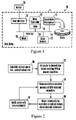
- FIG. 1 is a block diagram of a non-limiting HDD implementation of the present invention.
- FIG. 2 is a flow chart of the logic.
- a hard disk drive is shown, generally designated 10 , having a housing 11 holding a hard disk drive controller 12 that can include and/or be implemented by a microcontroller on a chip.
- the controller 12 may access electronic data storage in a computer program device or product such as but not limited to a microcode storage 14 that may be implemented by a solid state memory device.
- the microcode storage 14 can store microcode embodying the logic discussed further below.
- the HDD controller 12 controls a read/write mechanism 16 that includes one or more heads for writing data onto one or more disks 18 .
- Non-limiting implementations of the HDD 10 include plural heads and plural disks 18 , and each head is associated with a respective read element for, among other things, reading data on the disks 18 and a respective write element for writing data onto the disks 18 .
- the HDD controller 12 communicates with solid state memory.
- solid state memory may be volatile memory such as a Dynamic Random Access Memory (DRAM) device 20 .
- the controller 12 may communicate with solid state non-volatile memory, preferably a flash memory device 22 , over an internal HDD bus 24 .
- the HDD controller 12 also communicates with an external host computer 25 through a host interface module 26 in accordance with HDD principles known in the art.
- the host computer 25 can be a portable computer that can be powered by a battery, so that the HDD 10 can be a mobile HDD.
- the controller 12 with, e.g., DRAM 20 may be mounted on a HDD motherboard in accordance with principles known in the art.
- the logic disclosed below may be contained in a code storage 14 that is separate from the HDD controller 12 , or the storage 14 may be integrated into the controller 12 . Or, it may be contained in the read/write mechanism 16 , or on the DRAM 20 or flash memory device 22 .
- the logic may be distributed through the components mentioned above, and may be implemented in hardware logic circuits and/or software logic circuits.
- a desired cache size “N” and an optimal subset size “n”, which is less than the desired cache size “N”, are established.
- the sizes may be in terms of numbers of commands or total storage size.
- the optimal subset size “n” may be based on, e.g., age of commands, specifically, the optimal subset size may be based on a desire to execute a predetermined number of commands of age greater than some predetermined time period. Or, the optimal subset size “n” may be based on the highest number of commands that can be executed in a predetermined time period. Yet again, the optimal subset size “n” can be based on the greatest number of commands that can be executed in a predetermined number of rotations of the disk, or based on locations on the disk associated with the commands.
- Block 32 indicates that before outputting commands from the cache for execution to disk, the cache is filled to the desired cache size “N”.
- the desired cache size “N” is reached, i.e., when the cache stores the desired number of commands
- at block 34 substantially all “N” commands in the cache are evaluated using an execution optimization algorithm such as a greedy algorithm or a n-RPO algorithm, including expected NRPO algorithms.
- Block 36 indicates that of the “N” commands evaluated by the algorithm, only the “n” commands best fitting the criteria that were used to establish the optimal subset size “n” are executed to disk. These “n” commands may then be removed from the cache, but the remaining “N”-“n” commands remain in cache.
- the cache is refilled to the desired number “N” of commands prior to once again using an execution optimization algorithm to identify the “n” commands in the next successive optimal subset.
- the cache may be implemented in, e.g., the DRAM 20 or other solid state memory, or it may be implemented on a set-aside portion of the disk.
- the optimization algorithm will output, as its “top twenty” commands, those fitting the selection criteria. This can be modified by requiring that any command in cache that has been there longer than a predetermined period of time must be included in the next execution batch, potentially bumping one of the commands that would otherwise be in the optimal subset back into the queue for the next processing cycle.
- the “n” commands in the subset and only those commands may be output as a group by the optimization algorithm, or all “N” commands may be ordered and output by the optimization algorithm, in which case only the top “n” commands are executed.
- the remaining commands are evaluated once again in the next cycle, i.e., with the new “n” commands that have been added to bring the cache size back up to “N”.
Abstract
A desired cache size in a disk drive is established, and no reordering algorithm is performed on commands in the cache until the desired size is reached. An optimal subset size is also established. Then, an optimization algorithm is performed on all commands in the cache, with only the commands in the optimal subset being output for execution. The cache is refilled to the desired size, and the process is repeated.
Description
- The present invention relates generally to disk drives, and in particular to hard disk drives (HDD).
- In hard disk drives, when there are more than one command to execute, the data to be accessed next is chosen from a list or a queue of outstanding commands, typically in a solid state cache that may be implemented by, e.g., a dynamic random access memory (DRAM) or from a section (referred to as “L2”) of the disk that might be dedicated to cache-like functions, as set forth in, e.g., U.S. Pat. No. 6,378,037, incorporated herein by reference. In any case, when a hard disk drive has more than one command to execute, the commands are placed in a cache-implemented queue from which the next command is chosen. A Rotational Position Optimization (RPO) algorithm is used to reorder the commands for execution for optimal efficiency.
- Several variations have been proposed to the RPO paradigm. For instance, U.S. Pat. No. 6,859,859, incorporated herein by reference, discloses an effective RPO (“e-RPO”) method of command queue ordering in which, for each command in a command queue, an access time is calculated by identifying a probability of miss and adding a penalty for the identified probability of miss to the calculated access time. A command in the command queue having a best access time is identified and executed. Another variation is the so-called “n-RPO” method in which groups of commands are evaluated to maximize the number of queue commands that can be executed in a given number of disk revolutions. Yet another variation might combine the e-RPO and n-RPO methods.
- As critically recognized herein, many types of RPO-based algorithms happen to work more efficiently when the pool of available commands is large. Write caching and L2 caching increase the effective command set available to the RPO-based algorithms. The number of commands that can be placed in the write cache or L2 cache is limited by system resources. The cache must be effectively managed to optimize throughput. With this critical recognition in mind, the invention herein is provided.
- A controller for a hard disk drive that has a cache and at least one disk includes logic that, before outputting commands from the cache for execution to disk, fills the cache to a desired number of commands. When the cache stores the desired number of commands, the logic evaluates all commands in the cache using an execution optimization algorithm such as, e.g., a greedy algorithm, a NRPO algorithm, etc. The logic executes only an optimal subset of commands evaluated by the execution optimization algorithm, removing from cache only commands in the optimal subset, and leaving remaining commands in the cache. The cache is then refilled to the desired number of commands prior to once again using the execution optimization algorithm to identify a new optimal subset of commands.
- The optimal subset may be based on age of commands, most number of commands that can be executed in a predetermined time period, most number of commands that can be executed in a predetermined number of rotations of the disk, locations on the disk associated with the commands, or other heuristics. The cache may be implemented in solid state memory or on the disk itself.
- In another aspect, a data storage device has a disk, a data cache, and means for determining when a number of commands in the cache reaches a desired size. The device also includes means, responsive to the means for determining, for identifying a subset number of commands smaller than the desired size for execution.
- In yet another aspect, a disk drive controller receives commands into a cache and executes commands in the cache to disk. The controller includes logic implementing a command execution algorithm only when a desired cache size has been reached and executing only a subset of the commands less than the desired cache size prior to refilling the cache to the desired cache size. The details of the present invention, both as to its structure and operation, can best be understood in reference to the accompanying drawings, in which like reference numerals refer to like parts, and in which:
-
FIG. 1 is a block diagram of a non-limiting HDD implementation of the present invention; and -
FIG. 2 is a flow chart of the logic. - Referring initially to
FIG. 1 , a hard disk drive (HDD) is shown, generally designated 10, having a housing 11 holding a harddisk drive controller 12 that can include and/or be implemented by a microcontroller on a chip. Thecontroller 12 may access electronic data storage in a computer program device or product such as but not limited to amicrocode storage 14 that may be implemented by a solid state memory device. Themicrocode storage 14 can store microcode embodying the logic discussed further below. - The
HDD controller 12 controls a read/write mechanism 16 that includes one or more heads for writing data onto one ormore disks 18. Non-limiting implementations of theHDD 10 include plural heads andplural disks 18, and each head is associated with a respective read element for, among other things, reading data on thedisks 18 and a respective write element for writing data onto thedisks 18. - The
HDD controller 12 communicates with solid state memory. One such solid state memory may be volatile memory such as a Dynamic Random Access Memory (DRAM)device 20. Also, thecontroller 12 may communicate with solid state non-volatile memory, preferably aflash memory device 22, over aninternal HDD bus 24. TheHDD controller 12 also communicates with anexternal host computer 25 through ahost interface module 26 in accordance with HDD principles known in the art. Thehost computer 25 can be a portable computer that can be powered by a battery, so that theHDD 10 can be a mobile HDD. Thecontroller 12 with, e.g.,DRAM 20 may be mounted on a HDD motherboard in accordance with principles known in the art. - As stated above, the logic disclosed below may be contained in a
code storage 14 that is separate from theHDD controller 12, or thestorage 14 may be integrated into thecontroller 12. Or, it may be contained in the read/write mechanism 16, or on theDRAM 20 orflash memory device 22. The logic may be distributed through the components mentioned above, and may be implemented in hardware logic circuits and/or software logic circuits. - Now referring to
FIG. 2 , the present logic can be seen. Commencing atblock 30, a desired cache size “N” and an optimal subset size “n”, which is less than the desired cache size “N”, are established. The sizes may be in terms of numbers of commands or total storage size. The optimal subset size “n” may be based on, e.g., age of commands, specifically, the optimal subset size may be based on a desire to execute a predetermined number of commands of age greater than some predetermined time period. Or, the optimal subset size “n” may be based on the highest number of commands that can be executed in a predetermined time period. Yet again, the optimal subset size “n” can be based on the greatest number of commands that can be executed in a predetermined number of rotations of the disk, or based on locations on the disk associated with the commands. -
Block 32 indicates that before outputting commands from the cache for execution to disk, the cache is filled to the desired cache size “N”. When the desired cache size “N” is reached, i.e., when the cache stores the desired number of commands, atblock 34 substantially all “N” commands in the cache are evaluated using an execution optimization algorithm such as a greedy algorithm or a n-RPO algorithm, including expected NRPO algorithms. -
Block 36 indicates that of the “N” commands evaluated by the algorithm, only the “n” commands best fitting the criteria that were used to establish the optimal subset size “n” are executed to disk. These “n” commands may then be removed from the cache, but the remaining “N”-“n” commands remain in cache. Atblock 38 the cache is refilled to the desired number “N” of commands prior to once again using an execution optimization algorithm to identify the “n” commands in the next successive optimal subset. - The cache may be implemented in, e.g., the
DRAM 20 or other solid state memory, or it may be implemented on a set-aside portion of the disk. - The above strategies may be combined. For instance, if it is determined that the optimal subset size will be the greatest number of commands that can be executed to disk in four disk revolutions, then the optimization algorithm will output, as its “top twenty” commands, those fitting the selection criteria. This can be modified by requiring that any command in cache that has been there longer than a predetermined period of time must be included in the next execution batch, potentially bumping one of the commands that would otherwise be in the optimal subset back into the queue for the next processing cycle.
- The “n” commands in the subset and only those commands may be output as a group by the optimization algorithm, or all “N” commands may be ordered and output by the optimization algorithm, in which case only the top “n” commands are executed. The remaining commands are evaluated once again in the next cycle, i.e., with the new “n” commands that have been added to bring the cache size back up to “N”.
- While the particular SYSTEM AND METHOD FOR INCREMENTAL RPO-TYPE ALGORITHM IN DISK DRIVE as herein shown and described in detail is fully capable of attaining the above-described objects of the invention, it is to be understood that it is the presently preferred embodiment of the present invention and is thus representative of the subject matter which is broadly contemplated by the present invention, that the scope of the present invention fully encompasses other embodiments which may become obvious to those skilled in the art, and that the scope of the present invention is accordingly to be limited by nothing other than the appended claims, in which reference to an element in the singular is not intended to mean “one and only one” unless explicitly so stated, but rather “one or more”. It is not necessary for a device or method to address each and every problem sought to be solved by the present invention, for it to be encompassed by the present claims. Furthermore, no element, component, or method step in the present disclosure is intended to be dedicated to the public regardless of whether the element, component, or method step is explicitly recited in the claims. Absent express definitions herein, claim terms are to be given all ordinary and accustomed meanings that are not irreconcilable with the present specification and file history.
Claims (25)
1. A controller chip for a hard disk drive having at least one cache and at least one disk, comprising logic executing method acts including:
before outputting commands from the cache for execution to disk, filling the cache to a desired number of commands;
when the cache stores the desired number of commands, evaluating substantially all commands in the cache using an execution optimization algorithm;
executing only an optimal subset of commands evaluated by the execution optimization algorithm, removing from cache only commands in the optimal subset, and leaving remaining commands in the cache; and
refilling the cache to the desired number of commands prior to once again using an execution optimization algorithm.
2. The chip of claim 1 , wherein the optimal subset is based on age of commands.
3. The chip of claim 1 , wherein the optimal subset is based on most number of commands that can be executed in a predetermined time period.
4. The chip of claim 1 , wherein the optimal subset is based on most number of commands that can be executed in a predetermined number of rotations of the disk.
5. The chip of claim 1 , wherein the optimal subset is based on locations on the disk associated with the commands.
6. The chip of claim 1 , wherein the algorithm is a greedy algorithm
7. The chip of claim 1 , wherein the algorithm is a n-RPO algorithm.
8. The chip of claim 1 , wherein the cache is implemented in solid state memory.
9. The chip of claim 1 , wherein the cache is implemented on a portion of the disk.
10. A data storage device comprising:
at least one storage disk;
at least one data cache;
means for determining when a number of commands in the cache reaches a desired size; and
means, responsive to the means for determining, for identifying a subset number of commands smaller than the desired size for execution.
11. The device of claim 10 , comprising means for executing the subset without executing additional commands in the cache prior to the means for determining once again determining when the number of commands in the cache reaches the desired size.
12. The device of claim 10 , wherein the subset is based on age of commands.
13. The device of claim 10 , wherein the subset is based on most number of commands that can be executed in a predetermined time period and/or based on most number of commands that can be executed in a predetermined number of rotations of the disk.
14. The device of claim 10 , wherein the subset is based on locations on the disk associated with the commands.
15. The device of claim 10 , wherein the algorithm is a greedy algorithm.
16. The device of claim 10 , wherein the algorithm is a n-RPO algorithm.
17. The device of claim 10 , wherein the cache is implemented in solid state memory.
18. The device of claim 10 , wherein the cache is implemented on a portion of the disk.
19. A disk drive controller receiving commands into a cache and executing commands in the cache to disk, comprising:
logic implementing a command execution algorithm only when a desired cache size has been reached and executing only a subset of the commands less than the desired cache size prior to refilling the cache to the desired cache size.
20. The controller of claim 19 , wherein the subset is based on age of commands.
21. The controller of claim 19 , wherein the subset is based on most number of commands that can be executed in a predetermined time period.
22. The controller of claim 19 , wherein the subset is based on most number of commands that can be executed in a predetermined number of rotations of the disk.
23. The controller of claim 19 , wherein the subset is based on locations on the disk associated with the commands.
24. The controller of claim 19 , wherein the algorithm is a greedy algorithm.
25. The controller of claim 19 , wherein the algorithm is a n-RPO algorithm.
Priority Applications (1)
| Application Number | Priority Date | Filing Date | Title |
|---|---|---|---|
| US11/584,824 US20080098170A1 (en) | 2006-10-23 | 2006-10-23 | System and method for incremental RPO-type algorithm in disk drive |
Applications Claiming Priority (1)
| Application Number | Priority Date | Filing Date | Title |
|---|---|---|---|
| US11/584,824 US20080098170A1 (en) | 2006-10-23 | 2006-10-23 | System and method for incremental RPO-type algorithm in disk drive |
Publications (1)
| Publication Number | Publication Date |
|---|---|
| US20080098170A1 true US20080098170A1 (en) | 2008-04-24 |
Family
ID=39319416
Family Applications (1)
| Application Number | Title | Priority Date | Filing Date |
|---|---|---|---|
| US11/584,824 Abandoned US20080098170A1 (en) | 2006-10-23 | 2006-10-23 | System and method for incremental RPO-type algorithm in disk drive |
Country Status (1)
| Country | Link |
|---|---|
| US (1) | US20080098170A1 (en) |
Cited By (3)
| Publication number | Priority date | Publication date | Assignee | Title |
|---|---|---|---|---|
| US20080320217A1 (en) * | 2007-06-22 | 2008-12-25 | Levine Frank E | Executing I/O Requests For A Disk Drive |
| US20100146205A1 (en) * | 2008-12-08 | 2010-06-10 | Seagate Technology Llc | Storage device and method of writing data |
| US8838841B2 (en) | 2012-07-30 | 2014-09-16 | HGST Netherlands B.V. | Method and structure enabling improved native command queueing in a data storage device |
Citations (7)
| Publication number | Priority date | Publication date | Assignee | Title |
|---|---|---|---|---|
| US6374250B2 (en) * | 1997-02-03 | 2002-04-16 | International Business Machines Corporation | System and method for differential compression of data from a plurality of binary sources |
| US6378037B1 (en) * | 1999-06-29 | 2002-04-23 | International Business Machines Corporation | Write-twice method of fail-safe write caching |
| US20030163639A1 (en) * | 2002-02-25 | 2003-08-28 | Seagate Technology Llc | Sequential command processing mode in a disc drive using command queuing |
| US6674598B2 (en) * | 2001-05-14 | 2004-01-06 | Hitachi Global Technologies | Radial positioning of data to improve hard disk drive reliability |
| US6859859B2 (en) * | 2002-08-08 | 2005-02-22 | Hitachi Global Storage Technologies Netherlands, B.V. | Method and system for efficiently calculating and storing expected access time information for DASD |
| US20060218361A1 (en) * | 2005-03-25 | 2006-09-28 | Matsushita Electrical Industrial Co., Ltd. | Electronic storage device with rapid data availability |
| US20070043902A1 (en) * | 2005-08-22 | 2007-02-22 | Flake Lance L | Dual work queue disk drive controller |
-
2006
- 2006-10-23 US US11/584,824 patent/US20080098170A1/en not_active Abandoned
Patent Citations (7)
| Publication number | Priority date | Publication date | Assignee | Title |
|---|---|---|---|---|
| US6374250B2 (en) * | 1997-02-03 | 2002-04-16 | International Business Machines Corporation | System and method for differential compression of data from a plurality of binary sources |
| US6378037B1 (en) * | 1999-06-29 | 2002-04-23 | International Business Machines Corporation | Write-twice method of fail-safe write caching |
| US6674598B2 (en) * | 2001-05-14 | 2004-01-06 | Hitachi Global Technologies | Radial positioning of data to improve hard disk drive reliability |
| US20030163639A1 (en) * | 2002-02-25 | 2003-08-28 | Seagate Technology Llc | Sequential command processing mode in a disc drive using command queuing |
| US6859859B2 (en) * | 2002-08-08 | 2005-02-22 | Hitachi Global Storage Technologies Netherlands, B.V. | Method and system for efficiently calculating and storing expected access time information for DASD |
| US20060218361A1 (en) * | 2005-03-25 | 2006-09-28 | Matsushita Electrical Industrial Co., Ltd. | Electronic storage device with rapid data availability |
| US20070043902A1 (en) * | 2005-08-22 | 2007-02-22 | Flake Lance L | Dual work queue disk drive controller |
Cited By (3)
| Publication number | Priority date | Publication date | Assignee | Title |
|---|---|---|---|---|
| US20080320217A1 (en) * | 2007-06-22 | 2008-12-25 | Levine Frank E | Executing I/O Requests For A Disk Drive |
| US20100146205A1 (en) * | 2008-12-08 | 2010-06-10 | Seagate Technology Llc | Storage device and method of writing data |
| US8838841B2 (en) | 2012-07-30 | 2014-09-16 | HGST Netherlands B.V. | Method and structure enabling improved native command queueing in a data storage device |
Similar Documents
| Publication | Publication Date | Title |
|---|---|---|
| KR100909902B1 (en) | Flash memory device and Flash memory system | |
| US8769318B2 (en) | Asynchronous management of access requests to control power consumption | |
| US8255614B2 (en) | Information processing device that accesses memory, processor and memory management method | |
| US8874826B2 (en) | Programming method and device for a buffer cache in a solid-state disk system | |
| US8417880B2 (en) | System for NAND flash parameter auto-detection | |
| US20080016267A1 (en) | Memory controller, flash memory system having memory controller, and method for controlling flash memory | |
| US10909031B2 (en) | Memory system and operating method thereof | |
| US20110093659A1 (en) | Data storage device and data storing method thereof | |
| US20100318727A1 (en) | Memory system and related method of loading code | |
| JP2011154547A (en) | Memory management device and memory management method | |
| JP2004220557A (en) | Controller for xip in serial flash memory, its method and flash memory chip using the same | |
| JP2006114206A (en) | Hdd having both dram and flush memory | |
| US8667209B2 (en) | Non-volatile memory access method and system, and non-volatile memory controller | |
| US20140181378A1 (en) | Control device, control method, and program | |
| US20190391916A1 (en) | Method for managing flash memory module and associated flash memory controller and electronic device | |
| CN108228093B (en) | Method and apparatus for monitoring memory using background media scanning | |
| US20120331214A1 (en) | Defragmentation Method For A Machine-Readable Storage Device | |
| US8154925B2 (en) | Semiconductor memory device and system capable of executing an interleave programming for a plurality of memory chips and a 2-plane programming at the respective memory chips | |
| CN101606136A (en) | Be embodied as light storage device or/and the computer peripheral equipment of moveable magnetic disc and its implementation by software emulation | |
| US20080098170A1 (en) | System and method for incremental RPO-type algorithm in disk drive | |
| US8972650B2 (en) | Methods and systems for performing efficient page reads in a non-volatile memory | |
| US20020021595A1 (en) | Boot block flash memory control circuit; IC memory card and semiconductor memory device incorporating the same; and erasure method for boot block flash memory | |
| JP4634404B2 (en) | Nonvolatile memory and apparatus and method for determining data validity therefor | |
| US11861227B2 (en) | Storage device with task scheduler and method for operating the device | |
| US8291178B2 (en) | Machine-implemented method for categorizing storage media, and machine-implemented method for storing target codes |
Legal Events
| Date | Code | Title | Description |
|---|---|---|---|
| AS | Assignment |
Owner name: HITACHI GLOBAL STORAGE TECHNOLOGIES NETHERLAND B.V Free format text: ASSIGNMENT OF ASSIGNORS INTEREST;ASSIGNORS:GUTHRIE, WILLIAM L.;CHEN, JOE-MING;HEISE, NYLES NORBERT;REEL/FRAME:018468/0424;SIGNING DATES FROM 20060706 TO 20060927 |
|
| STCB | Information on status: application discontinuation |
Free format text: ABANDONED -- FAILURE TO RESPOND TO AN OFFICE ACTION |