US20080002869A1 - Registration of 3D imaging of 3D objects - Google Patents
Registration of 3D imaging of 3D objects Download PDFInfo
- Publication number
- US20080002869A1 US20080002869A1 US11/803,153 US80315307A US2008002869A1 US 20080002869 A1 US20080002869 A1 US 20080002869A1 US 80315307 A US80315307 A US 80315307A US 2008002869 A1 US2008002869 A1 US 2008002869A1
- Authority
- US
- United States
- Prior art keywords
- dental
- arches
- model
- recognition
- features
- Prior art date
- Legal status (The legal status is an assumption and is not a legal conclusion. Google has not performed a legal analysis and makes no representation as to the accuracy of the status listed.)
- Granted
Links
Images


Classifications
-
- A—HUMAN NECESSITIES
- A61—MEDICAL OR VETERINARY SCIENCE; HYGIENE
- A61C—DENTISTRY; APPARATUS OR METHODS FOR ORAL OR DENTAL HYGIENE
- A61C9/00—Impression cups, i.e. impression trays; Impression methods
- A61C9/004—Means or methods for taking digitized impressions
- A61C9/0046—Data acquisition means or methods
- A61C9/0053—Optical means or methods, e.g. scanning the teeth by a laser or light beam
-
- A—HUMAN NECESSITIES
- A61—MEDICAL OR VETERINARY SCIENCE; HYGIENE
- A61C—DENTISTRY; APPARATUS OR METHODS FOR ORAL OR DENTAL HYGIENE
- A61C13/00—Dental prostheses; Making same
-
- G—PHYSICS
- G06—COMPUTING; CALCULATING OR COUNTING
- G06F—ELECTRIC DIGITAL DATA PROCESSING
- G06F18/00—Pattern recognition
-
- G—PHYSICS
- G06—COMPUTING; CALCULATING OR COUNTING
- G06T—IMAGE DATA PROCESSING OR GENERATION, IN GENERAL
- G06T17/00—Three dimensional [3D] modelling, e.g. data description of 3D objects
-
- G—PHYSICS
- G06—COMPUTING; CALCULATING OR COUNTING
- G06T—IMAGE DATA PROCESSING OR GENERATION, IN GENERAL
- G06T7/00—Image analysis
- G06T7/30—Determination of transform parameters for the alignment of images, i.e. image registration
- G06T7/33—Determination of transform parameters for the alignment of images, i.e. image registration using feature-based methods
-
- G—PHYSICS
- G06—COMPUTING; CALCULATING OR COUNTING
- G06V—IMAGE OR VIDEO RECOGNITION OR UNDERSTANDING
- G06V20/00—Scenes; Scene-specific elements
- G06V20/60—Type of objects
- G06V20/64—Three-dimensional objects
- G06V20/653—Three-dimensional objects by matching three-dimensional models, e.g. conformal mapping of Riemann surfaces
-
- G—PHYSICS
- G06—COMPUTING; CALCULATING OR COUNTING
- G06T—IMAGE DATA PROCESSING OR GENERATION, IN GENERAL
- G06T2207/00—Indexing scheme for image analysis or image enhancement
- G06T2207/30—Subject of image; Context of image processing
- G06T2207/30004—Biomedical image processing
-
- G—PHYSICS
- G06—COMPUTING; CALCULATING OR COUNTING
- G06V—IMAGE OR VIDEO RECOGNITION OR UNDERSTANDING
- G06V2201/00—Indexing scheme relating to image or video recognition or understanding
- G06V2201/03—Recognition of patterns in medical or anatomical images
Definitions
- the invention relates to a method and system for determining the relative location of objects and features in a plurality of scanned images.
- the invention is particularly directed to medical and dental applications including those that require surgical and prosthetic devices to be designed and manufactured to precise dimensions dictated by the anatomy of individual patients, and still more particularly directed to the problem of registering, as precisely as possible, digitized 3-D scans of the mandible and maxilla of a patient or, equivalently, casts or impressions of same.
- implant procedures must adhere to very strict placement, orientation and sizing requirements determined by existing bone structure and dentition, whereby the prosthetic components to be fitted onto surgically-placed implant anchors must preferably be designed, shaped and sized specifically to conform to the precise anatomical geometry of the patient, including the location, shape and size of adjoining teeth, and must transition to the precise orientation of the principal axis of the supporting implant anchor with a high degree of accuracy.
- CAD computer aided design
- CAM computer aided manufacturing
- impression copings are affixed to the external extremity of the inserted implant anchors, and serve to reference the location and angular orientation of the anchors.
- a model made from a mold based on said impression will incorporate so-called “analog” anchors to model the anchors in the patient's jaw, and prosthetic devices for said anchors will be designed and manufactured based on the geometry of the model created as described.
- U.S. Pat. No. 5,851,115 issued Dec. 22, 1998 to Carlsson, et al describes a photogrammetric method and system for imaging the mouth, for the purpose of creating a virtual model of the patient's mouth from which dental parts may be designed and made.
- a specialized camera is employed, comprising a set of mirrors that enable a single exposure to embody stereographic images from two different angles.
- the system of Carlsson further requires that the relative geometry of the virtual “lenses” created by the mirror system be known precisely.
- Carlsson teaches the use of reference markings, such as circles, applied to flat surfaces within the imaged field.
- U.S. Pat. No. 5,857,853 issued Jan. 12, 1999 to van Nifteric et al. also discloses a photogrammetry-based method for capturing the dimensional and orientation data required for the manufacture of dental prosthetic parts used in implant dentistry.
- the method of van Nifteric et al employs either a plurality of cameras having precisely-known relative positions, or a single camera mounted on a swiveling carriage that is movable between separated but accurately defined positions.
- van Nifteric et al. further teach the use of recognition objects and points, to serve as reference points used by the photogrammetry software in positioning features of the imaged scene within a coordinate frame.
- van Nifteric et al. thus disclose the use of a bar comprising measuring scale markings, and of two spheres mounted on a pin, as recognition objects.
- prior art methods have depended on two methods that share a common characteristic: the first method relies on capturing the 3-D image of the facial surface of both the maxilla and the mandible in a single image. Separate, individual scans of the maxilla and mandible are then matched to the common template provided by the image of the facial surface of both maxilla and mandible.
- the second prior art method relies on capturing the “bite registration”, or impression of occlusal or biting surfaces of both the upper and lower teeth. After the geometry of the mandible has been captured, the bite registration is placed on the surface of the mandible and it also is scanned. The scan of the maxilla is then matched with the image of the matching surface of the bite registration.
- the object is scanned, using any suitable scanning means capable of capturing a cloud of data points representing three dimensional features of the scanned field.
- Such scanning typically requires the taking of a plurality of overlapping images that collectively span the image field to cover the required.
- Various methods are typically employed to recreate the entire three dimensional model from these separate scans.
- One such prior art method uses precise information about the location of the model with respect to the camera to position and orient the multiple images.
- commercially available three-dimensional image processing software products also provide tools to combine discrete scans into a single model by matching the overlapping regions of the images.
- suitable image-processing software include the Studio software marketed by Raindrop Geomagic, Inc.
- a three-dimensional-based modeling method and system designed for dentistry and related medical (and appropriate non-medical) applications.
- One aspect of the method and system dispenses with the need for a specific camera and instead enables the use of any data capture means that produces a point cloud representing the three dimensional surface.
- Such data capture means may for example be a hand-held or frame-fixed three-dimensional laser scanner, an ordinary digital camera, or any other imaging means that is practically suited to the particular medical application.
- Another aspect of the disclosure is the use of three-dimensional recognition objects, to enable the three-dimensional image processing software locate automatically, and determine accurately the position and orientation of objects within the image field.
- Yet another aspect of the disclosure is the positioning of recognition objects having well-defined topography within those areas in the image field that have low image definition, and particularly in such of these areas that appear in overlapping portions of at least two images, to provide the three-dimensional image processing software with position, angulation, and orientation information sufficient to enable highly accurate combining (or “stitching”) of adjoining and overlapping images.
- Still other aspects of the disclosure include methods for accurately capturing the spatial relationship of the maxilla and mandible, said methods not being dependent on the presence of dentition and therefore being fully usable to obtain accurate CAD modeling data even from patients who are partially or wholly edentulous.
- non-physiological recognition objects or geometry are added to the maxilla and mandible, or to casts representative of the patient's maxilla and mandible, in order to provide precisely accurate geometric references.
- an alternative method for capturing the relative position of the upper and lower components of a dental model makes use of the non-dental planar 3D geometry of these model components.
- the software registers position determining geometrical features of the model, from 3-D scan data, and employs known characteristics of said geometrical features to locate precisely and accurately all topographical features associated with the models including all anatomical and dental features.
- position determining geometrical features may be a minimum of three intersecting planes on each model component; such features may instead comprise combinations of planes, and/or features such as discs placed or painted on model component planes, spheres, or any other non-dental objects such as will provide unambiguous position data (6 degrees of freedom for each object).
- recognition objects having a known geometry that comprises well defined features disposed at accurately known or determinable relative positions are fixedly positioned within the image field, and particularly in areas within the image field that have low feature definition.
- recognition objects include one or more spheres having known radii, as well as one or more planar objects of known geometry and dimensions, such as pyramids.
- the image field is then scanned, such scanning effectively “panning” the image field to cover said image field to provide the needed geometry.
- Three-dimensional image processing software preferably comprising algorithms set forth in this specification, is then employed to combine the three-dimensional image data acquired by the scanning means and to determine a virtual three dimensional model that reconstructs, to a high degree of accuracy, the geometry of the scanned image field.
- This aspect of the invention serves to eliminate sources of inaccuracy resulting from the known “stitching” methods that result in drift, warp and/or other distortions as scans are aligned.
- FIG. 1 is a perspective view of a first recognition object usable according to the disclosed methods and system.
- FIG. 2 is a perspective view of a second recognition object usable according to the disclosed methods and system.
- FIG. 3 is a perspective view of a third recognition object usable according to the disclosed methods and system.
- FIG. 4 is a perspective view of a dental arch comprising a third recognition object.
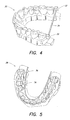
- FIG. 5 is a perspective view of a dental arch comprising a fourth recognition object.
- FIG. 6 is a perspective view of recognition objects placed externally to casts representing a patient's maxilla and mandible.
- FIG. 7 is a view of a cast of mandible comprising three internally placed recognition objects.
- FIG. 8 is a view of a cast of maxilla showing impressions made by the three recognition objects of the FIG. 7 cast.
- FIG. 9 is a view of the cast shown in FIG. 8 , now comprising spheres placed in impressions visible in FIG. 8
- FIG. 10 is a perspective view of an assembled dental model, showing characteristic planar surfaces.
- FIG. 11 is a perspective view of the lower component of the dental model of FIG. 10 .
- FIG. 12 is a perspective view of the upper component of the dental model of FIG. 10 .
- An aspect of the present invention is a method and system for creating virtual three-dimensional models of a scanned field of view, using non-physiological objects as reference points in the “stitching” of overlapping captured images, and, additionally, positioning such recognition objects in areas of the field of view that are characterized by low feature definition in order to enhance the accuracy of the three-dimensional modeling of such areas.
- a further aspect of the present invention is a method and system for obtaining 3-D data, usable in CAD and CAM applications, concerning the relative position of individual components such as the mandible and maxilla of a dental patient, especially when the 3-D data from each component must be scanned separately.
- Dental implants are used to support the restoration of missing teeth.
- Implant fixtures are surgically implanted by a dentist. These dental implants typically will be “restored” with abutments and crowns; that is, following successful implantation of implant fixtures into the jaw of the patient, complementary components including abutments and crowns will be affixed to the implanted fixtures to provide the patient with a restoration of the patient's natural teeth.
- a method and system in accordance with some embodiments of the present invention enables a manufacturer of dental restoration components to accurately measure the location and orientation of the implants in relation to the surrounding oral environment, and thereby to design and to machine restoration components that are, to a very high degree of precision and accuracy, customized to the anatomy and the existing dentition of the patient.
- Such methods and systems dispense with the need for specialized camera(s) and camera mountings. Instead they enable the use of any data capture means that produces a point cloud representing the three dimensional surface.
- data capture means may for example, be a hand-held or frame-fixed three-dimensional laser scanner, an ordinary digital camera, or any other imaging means that is practically suited to the particular medical application.
- Image-data capturing means usable with the invention are readily available from commercial sources, and would for example include three-dimensional laser scanners, such as the VIVID 900 model scanner marketed by the Minolta Corporation.
- Another aspect of the invention is the use of recognition objects, such as illustrated in FIGS. 1-6 and in FIG. 8 , to assist three-dimensional image processing software to locate automatically, and to determine accurately the position and orientation of objects within the image field.
- a still further aspect of the invention is the positioning of recognition objects having well-defined topography within those areas in the image field that have low image definition, and particularly in such of these areas that appear in overlapping portions of at least two images, to provide the imaging software with position and orientation information sufficient to enable highly accurate combining (or “stitching”) of adjoining and overlapping images.
- the presence of such areas of low feature definition is typical of edentulous dental conditions, and thus presents a chronic problem to the imaging of edentulous jaws, which the present invention is the first to address successfully.
- recognition objects having a known geometry that comprises well defined features disposed at accurately known or determinable relative positions are fixedly incorporated within the image field, and particularly in areas within the image field that have low feature definition.
- Some embodiments of recognition objects for use with this technology include an object, such as illustrated in FIG. 1 , that comprises three linked spheres 2 having precisely known radii, fixed at precisely known positions on angled posts 4 or an object comprising a three-dimensional shape 6 , such as illustrated in FIG. 2 .
- Another useful form of recognition object is the use of multiple planes as shown in FIG. 3 an example being a pyramidal polygon 8 of known dimensions.
- Still another useful form of recognition object is a simple sphere of known radius, as illustrated for example in FIGS. 5-7 and 9 (see, e.g., spheres 36 in arch 38 of FIG. 5 ).
- recognition objects as shown in FIGS. 1-4 are incorporated within the image field.
- one or more recognition objects can be secured to dental implants that have been surgically implanted into the jaw of the patient.
- recognition objects each comprise an attachment feature that is complementary to the interface features of the dental implant.
- the recognition objects can be secured with a fastener having a threaded shaft insertable within a bore of the recognition object that may be oriented along the principal axis of the implant fixture.
- the recognition objects may be secured to posts screwed into or otherwise secured to the casts.
- the invention comprises a method and system for developing a virtual three-dimensional model of a dental restoration field.
- the invention provides means for determining the relative location of recognition objects, and of features of recognition objects, in one or a plurality of scanned images obtained with a three-dimensional scanning means, and for detecting the location and the orientation of a known feature in a three-dimensional scanned object.
- the invention comprises a system and methods for accurately capturing the spatial relationship between two separate bodies, such as the maxilla and mandible of a dental patient, utilizing recognition objects positioned upon or secured to the bodies (i.e., to the maxilla and mandible or to casts or impressions representative of the maxilla and mandible).
- the recognition object can be an intrinsic, but non-anatomic, feature of an original object (or set of objects) as well as being an artifact that is added to the original object field. In either case the recognition object has known geometry. Using information about the known geometry of the recognition object, software enables the precise position and orientation of the recognition object to be identified with respect to the scanned data. Furthermore, multiple scans of a given field of view can be “registered” and their relative position and/or orientation precisely aligned, without any human intervention.
- the relative position and orientation of two or more objects may be accurately aligned with precision and a high degree of dimensional accuracy, using multiple scans of each field of view and at least one scan encompassing recognition objects from each of said fields of view.
- a field of view to be scanned must therefore comprise at least one object having one or more recognition features of known geometry and dimension, said features being sufficient to completely define location and/or orientation.
- recognition (location) object is scanned using a three-dimensional scanner, and the scanned data is often collected as unordered ASCII text format; however any collection of three-dimensional point data is applicable.
- the recognition object(s) are detected by the imaging software, and the determination of the position and/or orientation of each (using its known geometry) enables also the determination of the position and orientation of all other objects and features captured in the scanned data.
- This process can be rapidly executed in a fully automated process employing efficient computer code.
- the centers of the three spheres are detected by the software.
- An origin is then calculated using the geometric relationship, and the location of the origin is typically output as a data point triple (x,y,z).
- the software may also calculate the orientation of the recognition object as two unit vectors, also expressed as data point triples. Similar methods are employed to determine the position and orientation defined by other objects of known geometry within the subject field, such as the spherical, planar, polygonal, cylindrical and other shapes shown in FIGS. 1-7 . In this way a set of data is obtained that fully defines the position and orientation of each recognition object.
- Detecting an object of known geometry in a 3-dimensional scan has many potential applications.
- the medical and dental applications to which the present invention is principally directed involve a combination of organic surfaces and manufactured objects, and, in these applications, the ability to detect, to a high degree of accuracy, the position and orientation of an object of known geometry which is positioned within an anatomical field of view occasions the ability to design component parts that are customized to the topography of this anatomical field of view.
- the exact location and orientation of this part within the dental arch of the patient can be determined relative to other recognition objects.
- this determination permits a virtual assembly to be made that combines the scanned image and proposed replacement and supplemental part (i.e. a replacement tooth), in order to select, and then manufacture, replacement and supplemental parts that exactly complement the geometrical requirements of the patient's anatomical conditions.
- the placement of recognition objection within an edentulous region, or other region without significant anatomical features enables accurate registration of scans that contain the recognition object.
- This method can also be employed in conjunction with and to supplement currently practiced “stitching” or “registration” methods. These methods align multiple scans without the use of known geometry, but are insufficiently accurate for many applications.
- the described methodology enables the precise co-relation and registration of separate digitized scans of the maxilla and mandible of a dental patient (or of scans of casts representing, respectively, the maxilla and mandible of a patient).
- Three dimensional models developed from these methods enable an accurate definition of the positions and orientations of the maxilla and mandible, including a precise determination of the topographical aspects which determine occlusion characteristics.
- Such 3-D models may then be used to develop dental restorations that properly account for the optimal location/orientation of occlusal contacts and surfaces.
- a first method for effecting an accurate registration of the relative position of maxilla and mandible utilizes the recognition components illustrated in FIG. 6 .
- a set of three spheres 10 of known radii are affixed externally to, respectively, a cast of the patient's maxilla 12 and a cast of the patient's mandible 14 .
- a scan or set of scans that captures all of the spheres thus positioned on maxilla and mandible as shown on FIG. 6 can be used to construct a three-dimensional model that accurately represents the respective positions, orientations, and dimensions of the mandible and maxilla and their respective features.
- a single set of (preferably) three spheres is used.
- the set of spheres is positioned within the maxillar or mandibular arch of a patient, or, as in FIG. 7 , a cast 16 representing such an arch is made, and an “impression” is taken of the impact of that set of objects upon a pliable material placed within the opposing jaw element. Scans are then taken of the respective jaws 18 , either with the “impacted” surface left as is (as shown in FIG. 8 ) for imaging of the indentations 20 created by the recognition objects, or, for better illumination, following the placement of additional, identically-sized reflective spheres 22 within the indentations ( FIG. 9 ).
- FIG. 4 illustrates an example of this solution: in this case, a dental arch 30 is to be scanned.
- the known geometry introduced into the scan in the form of two polygons 32 of known dimensions, linked by a bar 34 also having a known dimension, enables detection of location and/or orientation of scans of portions of the teeth.
- Intra-oral scanning necessitates the use of small scanners, such that each scan enables the capture of only a portion of the arch.
- the present invention may be used in conjunction with the conventional practice whereby impressions are taken of the patient's dentition, and said dentition is replicated in the form of a master cast made from said impressions.
- the master cast will contain analogs of the dental implants. The accuracy with which the locations and orientations of these implant analogs can be determined, for the purpose of designing restoration component parts to be supported by the implants, is enhanced by using a recognition object according to the present invention.
- an alternative method for capturing the relative position of the upper and lower components of a dental model, and thereby for “aligning” said model components makes use of the non-dental planar 3D geometry of these model components.
- the software registers position determining geometrical features of the model, from scan data, and employs known characteristics of said geometrical features to locate precisely and accurately all topographical features associated with the models including all anatomical and dental features.
- Such position determining geometrical features may be a minimum of three intersecting planes on each model component; such features may instead comprise combinations of planes, and/or features such as discs placed or painted on model component planes, spheres, or any other non-dental objects such as will provide unambiguous position data (6 degrees of freedom for each object).
- a typical dental model comprising a lower component (shown separately in FIG. 11 ) and an upper component (shown separately in FIG. 12 ).
- dental models generally have multiple plane surfaces as a result of their preparation (or such planes can readily be added), and these planes provide a rich source of position-determining data, which can be extracted from scans of the model to serve as the basis for locating the positions of all topographical features associated with the model.
- Lower component 42 of model 40 comprises a plurality of planar surfaces, as artifacts of the preparation of the model, or created subsequently to the preparation of the model and specifically to serve as position-determining reference features.
- Said planar surfaces include a bottom plane 44 (not visible in FIG. 11 , but opposite lower dental arch 45 ), a back plane 46 , a first (e.g., right) side plane 48 and a second (e.g., left) side plane 50 .
- upper model component 52 shown separately in FIG. 12 , comprises a bottom plane 54 (not visible in FIG.
- each model component can be used as a reference feature (the “bottom” of a model component being the planar surface opposite the dental arch surface of the component).
- bottom plane 44 of lower model component 42 (shown separately in FIG. 11 ) is used as a reference plane; however, another planar surface of the either model component may be used instead as a reference.
- three planes were chosen for this example, but three or more planes or a combination of planes and other non-dental features could also have been chosen. (In some instances, one or more dental features can even be used as recognition features, augmented by planar and/or other non-dental features.)
- Alignment of the lower model component with the upper model component is implemented in this example by the use of three planes from each model component. It should be noted that, in the particular images of these respective model components employed to effect the alignment, the selected planes from the upper and lower models do not have to be aligned in any particular manner, in order to develop an accurate alignment of the upper and lower model components. (If non-planar features exist on or near the planes of interest, these can and generally should be removed using suitable processing techniques known in the art.)
- the assembled model ( FIG. 10 ) provides the relative location of the planes required for the assembly of the individual 3-D images respectively of the lower model component ( FIG. 11 ) and of the upper model component ( FIG. 12 ). Three planes from each model are selected. As the assembled model is illustrated in FIG. 10 , and as lower model component 42 is illustrated in FIG. 11 , bottom plane 44 of lower model 42 is not visible; likewise, in FIGS. 12 , bottom plane 54 of upper model component 52 is not visible. However, the bottom plane of each model component rests on the reference plane of the 3-D scanner at the time of scanning, preferably aligned with one or more reference markings, and therefore the geometrical orientation of these bottom planes in the scans is known.
- the geometry of lower model component 42 may be determined from knowledge of the plane of its bottom 44 (invisible in FIG. 11 ) and determination of lower component back plane 46 and lower component side plane 48 .
- the geometry of upper model component 52 may be determined from knowledge of the plane of its bottom 54 (invisible in FIG. 12 ) and determination of upper component back plane 56 upper lower component side plane 58 . Given the locations of the above planes the individual images can be assembled to match the locations of the planes in the assembly.
- More than three planes can also be used, as well as other objects that over-constrain the solution to the position of the model components (though if over-constrained a least squares, or similar solution, may typically be preferred).
- additional reference features may be attached to the planar surfaces of model component surfaces, also to serve as position-determining reference features.
- small circular disks of a color contrasting with that of the model surfaces may be painted on or otherwise adhered to any surface. Two or more such disks may also be disposed on the same planar surface at precisely measured spaced apart positions, thereby providing a scalar measure.
Abstract
Description
- This application is a continuation of U.S. patent application Ser. No. 11/184,396 filed Jul. 18, 2005, which is a continuation-in-part of U.S. patent application Ser. No. 10/154,717 filed May 24, 2002, which claims priority from Provisional Application Ser. No. 60/293,299 filed May 24, 2001.
- 1. Field of Invention
- The invention relates to a method and system for determining the relative location of objects and features in a plurality of scanned images. The invention is particularly directed to medical and dental applications including those that require surgical and prosthetic devices to be designed and manufactured to precise dimensions dictated by the anatomy of individual patients, and still more particularly directed to the problem of registering, as precisely as possible, digitized 3-D scans of the mandible and maxilla of a patient or, equivalently, casts or impressions of same.
- Many surgical procedures concern the temporary or permanent insertion, into the soft or bony tissue of a patient, of prosthetic and other artificial devices that are required to fit the anatomy of the patient to a very high degree of precision and accuracy. One such application concerns implant dentistry, in the course of which one or more (usually metallic) implant anchors are surgically placed within the jawbone of a patient, to receive and support prosthetic components designed to simulate and replace one or more natural teeth lost by the patient. It is well known that, to be wholly successful, implant procedures must adhere to very strict placement, orientation and sizing requirements determined by existing bone structure and dentition, whereby the prosthetic components to be fitted onto surgically-placed implant anchors must preferably be designed, shaped and sized specifically to conform to the precise anatomical geometry of the patient, including the location, shape and size of adjoining teeth, and must transition to the precise orientation of the principal axis of the supporting implant anchor with a high degree of accuracy.
- In addition, the development of many products and services provided in the fields of orthodontic and restorative dentistry seek to make use of computer aided design (CAD) and computer aided manufacturing (CAM). For example, in dentistry stone or plaster casts made from impressions of the patient's mouth are commonly used to provide the products or services needed, and three dimensional (3-D) scanning of either the patient's dentition or of casts representative of the patient's dentition are used to provide the dental CAD system with data representing the pertinent geometry. For such applications, however, very accurate alignment of the images of the maxilla (or of the upper cast replica) and the mandible (or of the lower cast replica) are needed for dental CAD modeling.
- Conventional methods for meeting these rigorous requirements provide for the creation of a model of the patient's jaw and dentition, the making of said model comprising the taking of a so-called “impression” of the patient's dentition, using a malleable substance placed over and around the teeth in the patient's mouth comprising the entire dental arch. Where the placement of implants and restorative components is a factor, typically this impression is taken following the surgical insertion of the implant anchors. Typically, reference components called impression copings are affixed to the external extremity of the inserted implant anchors, and serve to reference the location and angular orientation of the anchors. Subsequently, a model made from a mold based on said impression will incorporate so-called “analog” anchors to model the anchors in the patient's jaw, and prosthetic devices for said anchors will be designed and manufactured based on the geometry of the model created as described.
- In actual practice the conventional procedure described above is fraught with numerous difficulties and shortcomings. It has proven impossible for dental practitioners to make dental impressions, and thus models, that are consistently free of dimensional and positional errors; so rigorous are the geometrical requirements involved in such applications that even a sub-millimeter dimensioning error, or a 1 or 2 degree orientation error, will result in prosthetic placements that give rise to unacceptable stresses and conditions.
- In recent years efforts have been made to employ image-based modeling techniques to address these well-known problems of conventional implant dentistry procedures. In these efforts, images are taken of the patient's mouth, and a three-dimensional model of the pertinent regions is recreated using so-called three-dimensional image processing techniques and software. The field of photogrammetry, which traces its origins to the decade following the invention of photography in the 1830s, is “the art, science and technology of obtaining reliable information about physical objects and the environment through the processes of recording, measuring, and interpreting photographic images and patterns of electromagnetic radiant energy and other phenomena.” (Manual of Photogrammetry, American Society of Photogrammetry and Remote Sensing, 4th Ed., 1980). Particularly with the advent of computers having fast processing speeds and large memories, and the advent of low-cost digital cameras and other image-capture devices, off-the-shelf three-dimensional image processing software has become readily available that is applicable to a wide variety of virtual modeling applications. Using such software, it has become possible to reconstruct reasonably accurate three-dimensional models of an imaged subject field using available commercial products. However the particular demands for great accuracy, and the physical strictures of imaging the human body, have thus far resulted in the absence, in the field of dentistry, of acceptable three-dimensional imaging techniques. A particular problem is the necessity, for the accurate reconstruction, in the form of a virtual model, of an imaged scene. Typically, an object is imaged from more than one position, thereby providing a more complete three-dimensional model.
- U.S. Pat. No. 5,851,115 issued Dec. 22, 1998 to Carlsson, et al, describes a photogrammetric method and system for imaging the mouth, for the purpose of creating a virtual model of the patient's mouth from which dental parts may be designed and made. In the system according to Carlsson et al a specialized camera is employed, comprising a set of mirrors that enable a single exposure to embody stereographic images from two different angles. The system of Carlsson further requires that the relative geometry of the virtual “lenses” created by the mirror system be known precisely. To assist the software in locating and orienting imaged features, Carlsson teaches the use of reference markings, such as circles, applied to flat surfaces within the imaged field.
- U.S. Pat. No. 5,857,853 issued Jan. 12, 1999 to van Nifteric et al. also discloses a photogrammetry-based method for capturing the dimensional and orientation data required for the manufacture of dental prosthetic parts used in implant dentistry. In order to obtain the at-least-two views required by the triangulation engine of the photogrammetry software, the method of van Nifteric et al employs either a plurality of cameras having precisely-known relative positions, or a single camera mounted on a swiveling carriage that is movable between separated but accurately defined positions. van Nifteric et al. further teach the use of recognition objects and points, to serve as reference points used by the photogrammetry software in positioning features of the imaged scene within a coordinate frame. van Nifteric et al. thus disclose the use of a bar comprising measuring scale markings, and of two spheres mounted on a pin, as recognition objects.
- While the methods disclosed in the Carlsson et al. and van Nefteric et al. patents constitute significant advances, these methods still exhibit several important disadvantages and shortcomings that render them impractical for most implant dentistry practitioners. Both of said methods require the use of highly specialized and accordingly expensive camera equipment, and both require that such camera equipment be precisely aligned, to capture a plurality of images from precisely known relative lens positions. Functionally, both methods are inadequate to image accurately a wide field of view, particularly a wide field of view comprising areas characterized by very low feature definition, a condition typical of the edentulous (tooth-free) jaw and thus quite common in implant dentistry practice. The present invention addresses these shortcomings of the prior art, and it provides a three-dimensional-based virtual modeling method, specifically directed to medical and dental applications, that is remarkably low cost and that provides improved feature reconstruction accuracy particularly in applications that require the use of combined three-dimensional images.
- Specifically with respect to the problem of providing dental CAD systems with the relative position of maxilla and mandible, prior art methods have depended on two methods that share a common characteristic: the first method relies on capturing the 3-D image of the facial surface of both the maxilla and the mandible in a single image. Separate, individual scans of the maxilla and mandible are then matched to the common template provided by the image of the facial surface of both maxilla and mandible. The second prior art method relies on capturing the “bite registration”, or impression of occlusal or biting surfaces of both the upper and lower teeth. After the geometry of the mandible has been captured, the bite registration is placed on the surface of the mandible and it also is scanned. The scan of the maxilla is then matched with the image of the matching surface of the bite registration.
- Both of the prior art methods described in the preceding paragraph suffer from two fundamental problems. One problem is computational complexity, and the need to minimize even greater computational complexity by means of a good initial guess by a human operator regarding the relative position of the images being matched. A second and still greater difficulty arises where the patient is partially or completely edentulous, and there is lacking the 3-D information necessary to match the scans of maxilla and mandible. Also, it is difficult to obtain the geometry of anterior teeth from a bit registration.
- In some prior art, the object is scanned, using any suitable scanning means capable of capturing a cloud of data points representing three dimensional features of the scanned field. Such scanning typically requires the taking of a plurality of overlapping images that collectively span the image field to cover the required. Various methods are typically employed to recreate the entire three dimensional model from these separate scans. One such prior art method uses precise information about the location of the model with respect to the camera to position and orient the multiple images. In addition, commercially available three-dimensional image processing software products also provide tools to combine discrete scans into a single model by matching the overlapping regions of the images. Well-known examples of suitable image-processing software include the Studio software marketed by Raindrop Geomagic, Inc.
- Disclosed herein is a three-dimensional-based modeling method and system designed for dentistry and related medical (and appropriate non-medical) applications. One aspect of the method and system dispenses with the need for a specific camera and instead enables the use of any data capture means that produces a point cloud representing the three dimensional surface. Such data capture means may for example be a hand-held or frame-fixed three-dimensional laser scanner, an ordinary digital camera, or any other imaging means that is practically suited to the particular medical application.
- Another aspect of the disclosure is the use of three-dimensional recognition objects, to enable the three-dimensional image processing software locate automatically, and determine accurately the position and orientation of objects within the image field.
- Yet another aspect of the disclosure is the positioning of recognition objects having well-defined topography within those areas in the image field that have low image definition, and particularly in such of these areas that appear in overlapping portions of at least two images, to provide the three-dimensional image processing software with position, angulation, and orientation information sufficient to enable highly accurate combining (or “stitching”) of adjoining and overlapping images.
- Still other aspects of the disclosure include methods for accurately capturing the spatial relationship of the maxilla and mandible, said methods not being dependent on the presence of dentition and therefore being fully usable to obtain accurate CAD modeling data even from patients who are partially or wholly edentulous. In the methods disclosed, non-physiological recognition objects or geometry are added to the maxilla and mandible, or to casts representative of the patient's maxilla and mandible, in order to provide precisely accurate geometric references.
- In another aspect of the invention, an alternative method for capturing the relative position of the upper and lower components of a dental model makes use of the non-dental planar 3D geometry of these model components. In this alternative method the software registers position determining geometrical features of the model, from 3-D scan data, and employs known characteristics of said geometrical features to locate precisely and accurately all topographical features associated with the models including all anatomical and dental features. Such position determining geometrical features may be a minimum of three intersecting planes on each model component; such features may instead comprise combinations of planes, and/or features such as discs placed or painted on model component planes, spheres, or any other non-dental objects such as will provide unambiguous position data (6 degrees of freedom for each object).
- In these methods, recognition objects having a known geometry that comprises well defined features disposed at accurately known or determinable relative positions, are fixedly positioned within the image field, and particularly in areas within the image field that have low feature definition. Examples of recognition objects include one or more spheres having known radii, as well as one or more planar objects of known geometry and dimensions, such as pyramids. The image field is then scanned, such scanning effectively “panning” the image field to cover said image field to provide the needed geometry. Three-dimensional image processing software, preferably comprising algorithms set forth in this specification, is then employed to combine the three-dimensional image data acquired by the scanning means and to determine a virtual three dimensional model that reconstructs, to a high degree of accuracy, the geometry of the scanned image field.
- By using physically connected, known geometric features as recognition objects in individual, overlapping or non-overlapping images that collectively cover the field of view of interest, the relative position and orientation of these images can thus be determined. This aspect of the invention serves to eliminate sources of inaccuracy resulting from the known “stitching” methods that result in drift, warp and/or other distortions as scans are aligned.
-
FIG. 1 is a perspective view of a first recognition object usable according to the disclosed methods and system. -
FIG. 2 is a perspective view of a second recognition object usable according to the disclosed methods and system. -
FIG. 3 is a perspective view of a third recognition object usable according to the disclosed methods and system. -
FIG. 4 is a perspective view of a dental arch comprising a third recognition object. -
FIG. 5 is a perspective view of a dental arch comprising a fourth recognition object. -
FIG. 6 is a perspective view of recognition objects placed externally to casts representing a patient's maxilla and mandible. -
FIG. 7 is a view of a cast of mandible comprising three internally placed recognition objects. -
FIG. 8 is a view of a cast of maxilla showing impressions made by the three recognition objects of theFIG. 7 cast. -
FIG. 9 is a view of the cast shown inFIG. 8 , now comprising spheres placed in impressions visible inFIG. 8 -
FIG. 10 is a perspective view of an assembled dental model, showing characteristic planar surfaces. -
FIG. 11 is a perspective view of the lower component of the dental model ofFIG. 10 . -
FIG. 12 is a perspective view of the upper component of the dental model ofFIG. 10 . - Various aspects of the above-referenced methods and systems will now be presented. In presenting these aspects, embodiments will be used to illustrate features of such methods and systems. It should be understood that these embodiments are shown by way of example only, and are not intended to be limiting in any way. The invention may be embodied both in these and in numerous other forms. While these embodiments illustrate various combinations of elements and acts, it should be appreciated that some or all of such elements or acts may be assembled or practiced in other ways, with or without still further elements or acts, while still practicing the invention.
- As used herein, certain terms or expressions should be understood to have the following meanings unless contextual usage clearly indicates otherwise: “Adjacent” the surface of an arch includes placement directly on the arch or spaced slightly therefrom. “Interiorly” and “exteriorly” relate to features toward the interior or exterior, respectively, of a mouth; interiorly or exteriorly with respect to an arch relates to the region within the U-shape of an arch or along the outside of a U-shaped arch, respectively. An edentulous arch is one having no teeth. An arch having an edentulous region has one or more teeth and a portion missing one or more teeth.
- An aspect of the present invention is a method and system for creating virtual three-dimensional models of a scanned field of view, using non-physiological objects as reference points in the “stitching” of overlapping captured images, and, additionally, positioning such recognition objects in areas of the field of view that are characterized by low feature definition in order to enhance the accuracy of the three-dimensional modeling of such areas.
- A further aspect of the present invention is a method and system for obtaining 3-D data, usable in CAD and CAM applications, concerning the relative position of individual components such as the mandible and maxilla of a dental patient, especially when the 3-D data from each component must be scanned separately.
- The described systems and methods are particularly suitable and intended for medical and dental applications, and are particularly suited for use in the field of implant dentistry and related applications. Dental implants are used to support the restoration of missing teeth. Implant fixtures are surgically implanted by a dentist. These dental implants typically will be “restored” with abutments and crowns; that is, following successful implantation of implant fixtures into the jaw of the patient, complementary components including abutments and crowns will be affixed to the implanted fixtures to provide the patient with a restoration of the patient's natural teeth.
- In an aspect, a method and system in accordance with some embodiments of the present invention enables a manufacturer of dental restoration components to accurately measure the location and orientation of the implants in relation to the surrounding oral environment, and thereby to design and to machine restoration components that are, to a very high degree of precision and accuracy, customized to the anatomy and the existing dentition of the patient.
- In applications directed to dentistry, and related medical applications, such methods and systems dispense with the need for specialized camera(s) and camera mountings. Instead they enable the use of any data capture means that produces a point cloud representing the three dimensional surface. Such data capture means may for example, be a hand-held or frame-fixed three-dimensional laser scanner, an ordinary digital camera, or any other imaging means that is practically suited to the particular medical application. Image-data capturing means usable with the invention are readily available from commercial sources, and would for example include three-dimensional laser scanners, such as the VIVID 900 model scanner marketed by the Minolta Corporation.
- Another aspect of the invention is the use of recognition objects, such as illustrated in
FIGS. 1-6 and inFIG. 8 , to assist three-dimensional image processing software to locate automatically, and to determine accurately the position and orientation of objects within the image field. - A still further aspect of the invention is the positioning of recognition objects having well-defined topography within those areas in the image field that have low image definition, and particularly in such of these areas that appear in overlapping portions of at least two images, to provide the imaging software with position and orientation information sufficient to enable highly accurate combining (or “stitching”) of adjoining and overlapping images. The presence of such areas of low feature definition is typical of edentulous dental conditions, and thus presents a chronic problem to the imaging of edentulous jaws, which the present invention is the first to address successfully.
- In practicing the approach taught herein, recognition objects having a known geometry that comprises well defined features disposed at accurately known or determinable relative positions, are fixedly incorporated within the image field, and particularly in areas within the image field that have low feature definition. Some embodiments of recognition objects for use with this technology include an object, such as illustrated in
FIG. 1 , that comprises three linkedspheres 2 having precisely known radii, fixed at precisely known positions onangled posts 4 or an object comprising a three-dimensional shape 6, such as illustrated inFIG. 2 . Another useful form of recognition object is the use of multiple planes as shown inFIG. 3 an example being apyramidal polygon 8 of known dimensions. Still another useful form of recognition object is a simple sphere of known radius, as illustrated for example inFIGS. 5-7 and 9 (see, e.g.,spheres 36 inarch 38 ofFIG. 5 ). - In the practice of the method taught herein, recognition objects as shown in
FIGS. 1-4 are incorporated within the image field. In the case of implant dentistry, one or more recognition objects can be secured to dental implants that have been surgically implanted into the jaw of the patient. Preferably, such recognition objects each comprise an attachment feature that is complementary to the interface features of the dental implant. The recognition objects can be secured with a fastener having a threaded shaft insertable within a bore of the recognition object that may be oriented along the principal axis of the implant fixture. Where the field of view comprises articulated casts of the maxilla and mandible of a patient, the recognition objects may be secured to posts screwed into or otherwise secured to the casts. - According to another aspect, the invention comprises a method and system for developing a virtual three-dimensional model of a dental restoration field. In one aspect, the invention provides means for determining the relative location of recognition objects, and of features of recognition objects, in one or a plurality of scanned images obtained with a three-dimensional scanning means, and for detecting the location and the orientation of a known feature in a three-dimensional scanned object.
- In another aspect, the invention comprises a system and methods for accurately capturing the spatial relationship between two separate bodies, such as the maxilla and mandible of a dental patient, utilizing recognition objects positioned upon or secured to the bodies (i.e., to the maxilla and mandible or to casts or impressions representative of the maxilla and mandible).
- The recognition object can be an intrinsic, but non-anatomic, feature of an original object (or set of objects) as well as being an artifact that is added to the original object field. In either case the recognition object has known geometry. Using information about the known geometry of the recognition object, software enables the precise position and orientation of the recognition object to be identified with respect to the scanned data. Furthermore, multiple scans of a given field of view can be “registered” and their relative position and/or orientation precisely aligned, without any human intervention. Similarly the relative position and orientation of two or more objects, notably including fields of view consisting of two separately scanned components, such as maxilla and mandible, or their representative casts, may be accurately aligned with precision and a high degree of dimensional accuracy, using multiple scans of each field of view and at least one scan encompassing recognition objects from each of said fields of view.
- A field of view to be scanned must therefore comprise at least one object having one or more recognition features of known geometry and dimension, said features being sufficient to completely define location and/or orientation. Non-limiting examples of these types of objects are shown in
FIGS. 1-7 . The recognition (location) object is scanned using a three-dimensional scanner, and the scanned data is often collected as unordered ASCII text format; however any collection of three-dimensional point data is applicable. - From the scanned data the recognition object(s) are detected by the imaging software, and the determination of the position and/or orientation of each (using its known geometry) enables also the determination of the position and orientation of all other objects and features captured in the scanned data.
- This process can be rapidly executed in a fully automated process employing efficient computer code. For example, in the example of three spheres used to define position and orientation (see
FIG. 1 ), the centers of the three spheres (of known diameter and known distance from each other) are detected by the software. An origin is then calculated using the geometric relationship, and the location of the origin is typically output as a data point triple (x,y,z). The software may also calculate the orientation of the recognition object as two unit vectors, also expressed as data point triples. Similar methods are employed to determine the position and orientation defined by other objects of known geometry within the subject field, such as the spherical, planar, polygonal, cylindrical and other shapes shown inFIGS. 1-7 . In this way a set of data is obtained that fully defines the position and orientation of each recognition object. - Detecting an object of known geometry in a 3-dimensional scan has many potential applications. The medical and dental applications to which the present invention is principally directed involve a combination of organic surfaces and manufactured objects, and, in these applications, the ability to detect, to a high degree of accuracy, the position and orientation of an object of known geometry which is positioned within an anatomical field of view occasions the ability to design component parts that are customized to the topography of this anatomical field of view.
- Specifically in the case of dental implants, for example, by mounting one of the recognition objects shown in
FIGS. 1-3 onto the existing manufactured part (i.e., the implant itself), the exact location and orientation of this part within the dental arch of the patient can be determined relative to other recognition objects. In turn, this determination permits a virtual assembly to be made that combines the scanned image and proposed replacement and supplemental part (i.e. a replacement tooth), in order to select, and then manufacture, replacement and supplemental parts that exactly complement the geometrical requirements of the patient's anatomical conditions. Furthermore, the placement of recognition objection within an edentulous region, or other region without significant anatomical features, enables accurate registration of scans that contain the recognition object. - When multiple three-dimensional images of an object are taken (e.g. due to size or obscured views), it is necessary to define the relative location and orientation of each of the images in order to re-align the captured image data into a complete and accurate representation of the original field of view. In order to do this, there must be captured, in each image in the set of images, a recognition object of known geometry (such as those shown in
FIGS. 1-7 ), which also appears in a second image in the set. The location and/or orientation of the known object in each image can then be used to position the images with respect to each other in order to recreate the original field of view. - This method can also be employed in conjunction with and to supplement currently practiced “stitching” or “registration” methods. These methods align multiple scans without the use of known geometry, but are insufficiently accurate for many applications. The addition to the field of view of one or more recognition objects according to the invention, as illustrated for example in
FIGS. 1-6 , greatly enhances the accuracy of the stitching of adjoining images. Furthermore the positioning of such recognition objects within any areas of the field of view that are characterized by low feature definition will greatly enhance the three-dimensional modeling of such areas, in addition to serving as relative reference points between adjoining images that each comprise a given recognition object. - In particular, the described methodology enables the precise co-relation and registration of separate digitized scans of the maxilla and mandible of a dental patient (or of scans of casts representing, respectively, the maxilla and mandible of a patient). Three dimensional models developed from these methods enable an accurate definition of the positions and orientations of the maxilla and mandible, including a precise determination of the topographical aspects which determine occlusion characteristics. Such 3-D models may then be used to develop dental restorations that properly account for the optimal location/orientation of occlusal contacts and surfaces.
- A first method for effecting an accurate registration of the relative position of maxilla and mandible utilizes the recognition components illustrated in
FIG. 6 . As shown inFIG. 6 , a set of threespheres 10 of known radii are affixed externally to, respectively, a cast of the patient'smaxilla 12 and a cast of the patient'smandible 14. Following separately-effected digitized scans of maxilla and mandible, a scan or set of scans that captures all of the spheres thus positioned on maxilla and mandible as shown onFIG. 6 can be used to construct a three-dimensional model that accurately represents the respective positions, orientations, and dimensions of the mandible and maxilla and their respective features. - In a second method according to the invention, for developing a 3-D model of the articulated relation between the maxilla and mandible of a patient, only a single set of (preferably) three spheres is used. The set of spheres is positioned within the maxillar or mandibular arch of a patient, or, as in
FIG. 7 , acast 16 representing such an arch is made, and an “impression” is taken of the impact of that set of objects upon a pliable material placed within the opposing jaw element. Scans are then taken of therespective jaws 18, either with the “impacted” surface left as is (as shown inFIG. 8 ) for imaging of theindentations 20 created by the recognition objects, or, for better illumination, following the placement of additional, identically-sizedreflective spheres 22 within the indentations (FIG. 9 ). - By using physically connected, known geometric features as recognition objects in individual, overlapping or non-overlapping images that collectively cover the field of view of interest, the relative position and orientation of these images can thus be determined. This aspect of the invention serves to eliminate sources of inaccuracy resulting from the known “stitching” methods that result in drift, warp and/or other distortions as scans are aligned.
FIG. 4 illustrates an example of this solution: in this case, adental arch 30 is to be scanned. The known geometry introduced into the scan, in the form of twopolygons 32 of known dimensions, linked by abar 34 also having a known dimension, enables detection of location and/or orientation of scans of portions of the teeth. Intra-oral scanning necessitates the use of small scanners, such that each scan enables the capture of only a portion of the arch. - In the practice of the invention, spatial information may be obtained directly using intra-oral scanning and then processed as described above. As described above, however, the present invention may be used in conjunction with the conventional practice whereby impressions are taken of the patient's dentition, and said dentition is replicated in the form of a master cast made from said impressions. In an implant case, the master cast will contain analogs of the dental implants. The accuracy with which the locations and orientations of these implant analogs can be determined, for the purpose of designing restoration component parts to be supported by the implants, is enhanced by using a recognition object according to the present invention.
- In another aspect of the invention, an alternative method for capturing the relative position of the upper and lower components of a dental model, and thereby for “aligning” said model components, makes use of the non-dental planar 3D geometry of these model components. In this alternative method the software registers position determining geometrical features of the model, from scan data, and employs known characteristics of said geometrical features to locate precisely and accurately all topographical features associated with the models including all anatomical and dental features. Such position determining geometrical features may be a minimum of three intersecting planes on each model component; such features may instead comprise combinations of planes, and/or features such as discs placed or painted on model component planes, spheres, or any other non-dental objects such as will provide unambiguous position data (6 degrees of freedom for each object).
- Referring to
FIGS. 10, 11 , and 12, a typical dental model is illustrated, comprising a lower component (shown separately inFIG. 11 ) and an upper component (shown separately inFIG. 12 ). As shown inFIGS. 10-12 , dental models generally have multiple plane surfaces as a result of their preparation (or such planes can readily be added), and these planes provide a rich source of position-determining data, which can be extracted from scans of the model to serve as the basis for locating the positions of all topographical features associated with the model. - Referring to
FIG. 11 , there is illustratedlower component 42 ofmodel 40.Lower component 42 comprises a plurality of planar surfaces, as artifacts of the preparation of the model, or created subsequently to the preparation of the model and specifically to serve as position-determining reference features. Said planar surfaces include a bottom plane 44 (not visible inFIG. 11 , but opposite lower dental arch 45), aback plane 46, a first (e.g., right)side plane 48 and a second (e.g., left)side plane 50. Similarly,upper model component 52, shown separately inFIG. 12 , comprises a bottom plane 54 (not visible inFIG. 12 , but opposite upper dental arch 55), aback plane 56, afirst plane 58, and asecond plane 60. In particular, the planar surface forming the “bottom” of each model component can be used as a reference feature (the “bottom” of a model component being the planar surface opposite the dental arch surface of the component). In the following example,bottom plane 44 of lower model component 42 (shown separately inFIG. 11 ) is used as a reference plane; however, another planar surface of the either model component may be used instead as a reference. Similarly, three planes were chosen for this example, but three or more planes or a combination of planes and other non-dental features could also have been chosen. (In some instances, one or more dental features can even be used as recognition features, augmented by planar and/or other non-dental features.) - Alignment of the lower model component with the upper model component is implemented in this example by the use of three planes from each model component. It should be noted that, in the particular images of these respective model components employed to effect the alignment, the selected planes from the upper and lower models do not have to be aligned in any particular manner, in order to develop an accurate alignment of the upper and lower model components. (If non-planar features exist on or near the planes of interest, these can and generally should be removed using suitable processing techniques known in the art.)
- The assembled model (
FIG. 10 ) provides the relative location of the planes required for the assembly of the individual 3-D images respectively of the lower model component (FIG. 11 ) and of the upper model component (FIG. 12 ). Three planes from each model are selected. As the assembled model is illustrated inFIG. 10 , and aslower model component 42 is illustrated inFIG. 11 ,bottom plane 44 oflower model 42 is not visible; likewise, inFIGS. 12 ,bottom plane 54 ofupper model component 52 is not visible. However, the bottom plane of each model component rests on the reference plane of the 3-D scanner at the time of scanning, preferably aligned with one or more reference markings, and therefore the geometrical orientation of these bottom planes in the scans is known. - Since the bottom plane in each of the three images (assembled, lower, and upper) is known, then, for each of the upper and lower components, only two additional planes, each visible in both the separate image of the component and the image of the assembly, need to be determined by the software in order to determine precisely the geometry of that component. Similarly, for determining the geometry, and thus the alignment of upper and lower components, of the fully assembled model, there must be determined, from its image as represented in
FIG. 10 , the two planes selected from each of the model components plus only the previously invisible, but “known”,bottom plane 54 ofupper model component 52. - For example, the geometry of
lower model component 42 may be determined from knowledge of the plane of its bottom 44 (invisible inFIG. 11 ) and determination of lower component backplane 46 and lowercomponent side plane 48. Similarly the geometry ofupper model component 52 may be determined from knowledge of the plane of its bottom 54 (invisible inFIG. 12 ) and determination of upper component backplane 56 upper lowercomponent side plane 58. Given the locations of the above planes the individual images can be assembled to match the locations of the planes in the assembly. - Thus, to implement the alignment of the upper and lower model components of
model 40, from the image of the assembled model shown inFIG. 10 , it is necessary only to determine the orientation, in this image, of the four planes (two from each model component) described above (that is, upper component backplane 46 andside plane 48, and lower component back 56 and side plane 58), and additionally, to determine the orientation, as shown inFIG. 10 , of uppercomponent bottom plane 54. - More than three planes can also be used, as well as other objects that over-constrain the solution to the position of the model components (though if over-constrained a least squares, or similar solution, may typically be preferred). Optionally, additional reference features may be attached to the planar surfaces of model component surfaces, also to serve as position-determining reference features. For example, small circular disks of a color contrasting with that of the model surfaces, may be painted on or otherwise adhered to any surface. Two or more such disks may also be disposed on the same planar surface at precisely measured spaced apart positions, thereby providing a scalar measure.
Claims (14)
Priority Applications (1)
| Application Number | Priority Date | Filing Date | Title |
|---|---|---|---|
| US11/803,153 US7551760B2 (en) | 2001-05-24 | 2007-05-11 | Registration of 3D imaging of 3D objects |
Applications Claiming Priority (4)
| Application Number | Priority Date | Filing Date | Title |
|---|---|---|---|
| US29329901P | 2001-05-24 | 2001-05-24 | |
| US10/154,717 US6925198B2 (en) | 2002-05-24 | 2002-05-24 | Method and system for three-dimensional modeling of object fields |
| US11/184,396 US7362890B2 (en) | 2001-05-24 | 2005-07-18 | Registration of 3-D imaging of 3-D objects |
| US11/803,153 US7551760B2 (en) | 2001-05-24 | 2007-05-11 | Registration of 3D imaging of 3D objects |
Related Parent Applications (1)
| Application Number | Title | Priority Date | Filing Date |
|---|---|---|---|
| US11/184,396 Continuation US7362890B2 (en) | 2001-05-24 | 2005-07-18 | Registration of 3-D imaging of 3-D objects |
Publications (2)
| Publication Number | Publication Date |
|---|---|
| US20080002869A1 true US20080002869A1 (en) | 2008-01-03 |
| US7551760B2 US7551760B2 (en) | 2009-06-23 |
Family
ID=37392981
Family Applications (2)
| Application Number | Title | Priority Date | Filing Date |
|---|---|---|---|
| US11/184,396 Expired - Fee Related US7362890B2 (en) | 2001-05-24 | 2005-07-18 | Registration of 3-D imaging of 3-D objects |
| US11/803,153 Expired - Fee Related US7551760B2 (en) | 2001-05-24 | 2007-05-11 | Registration of 3D imaging of 3D objects |
Family Applications Before (1)
| Application Number | Title | Priority Date | Filing Date |
|---|---|---|---|
| US11/184,396 Expired - Fee Related US7362890B2 (en) | 2001-05-24 | 2005-07-18 | Registration of 3-D imaging of 3-D objects |
Country Status (11)
| Country | Link |
|---|---|
| US (2) | US7362890B2 (en) |
| EP (2) | EP2431944A1 (en) |
| JP (1) | JP5011292B2 (en) |
| KR (1) | KR101279292B1 (en) |
| CN (1) | CN101228556B (en) |
| AT (1) | ATE539418T1 (en) |
| AU (1) | AU2006269977B2 (en) |
| BR (1) | BRPI0613627A2 (en) |
| CA (1) | CA2615482A1 (en) |
| ES (1) | ES2380547T3 (en) |
| WO (1) | WO2007011909A1 (en) |
Cited By (20)
| Publication number | Priority date | Publication date | Assignee | Title |
|---|---|---|---|---|
| US20030214501A1 (en) * | 2002-04-29 | 2003-11-20 | Hultgren Bruce Willard | Method and apparatus for electronically generating a color dental occlusion map within electronic model images |
| US20030220778A1 (en) * | 2002-04-29 | 2003-11-27 | Hultgren Bruce Willard | Method and apparatus for electronically simulating jaw function within electronic model images |
| US20050203726A1 (en) * | 2004-03-11 | 2005-09-15 | Marshall Michael C. | System and method for generating an electronic model for a dental impression having a common coordinate system |
| US20060095242A1 (en) * | 2004-03-11 | 2006-05-04 | Marshall Michael C | System and method for determining condyle displacement utilizing electronic models of dental impressions having a common coordinate system |
| US20080176182A1 (en) * | 2006-10-05 | 2008-07-24 | Bruce Willard Hultgren | System and method for electronically modeling jaw articulation |
| US20090280451A1 (en) * | 2008-05-08 | 2009-11-12 | 6615546 Canada Inc., D.B.A. Dental Wings, Inc. | Dental articulator reference object |
| US8602773B2 (en) | 2006-10-27 | 2013-12-10 | Nobel Biocare Services Ag | Dental impression tray for use in obtaining an impression of a dental structure |
| WO2016110855A1 (en) * | 2015-01-08 | 2016-07-14 | Dentlytec G.P.L. Ltd | System, device, and method for improved intraoral scanning accuracy |
| US9439608B2 (en) | 2007-04-20 | 2016-09-13 | Medicim Nv | Method for deriving shape information |
| US9454846B2 (en) | 2012-12-24 | 2016-09-27 | Dentlytec G.P.L. Ltd. | Device and method for subgingival measurement |
| US10136970B2 (en) | 2015-01-18 | 2018-11-27 | Dentlytec G.P.L.Ltd | System, device, and method for dental intraoral scanning |
| EP2410938B1 (en) * | 2009-03-23 | 2019-10-02 | BEGO Implant Systems GmbH & Co. KG | Scanning body for tooth implants |
| US10456229B2 (en) | 2014-05-09 | 2019-10-29 | 3Shape A/S | Scanning of edentulous patients |
| WO2021046147A1 (en) | 2019-09-05 | 2021-03-11 | Dentsply Sirona Inc. | Method, system and devices for instant automated design of a customized dental object |
| US10966614B2 (en) | 2015-01-18 | 2021-04-06 | Dentlytec G.P.L. Ltd. | Intraoral scanner |
| US11173011B2 (en) | 2015-05-01 | 2021-11-16 | Dentlytec G.P.L. Ltd. | System, device and methods for dental digital impressions |
| US20220156953A1 (en) * | 2019-03-12 | 2022-05-19 | Modjaw | Method for registering virtual models of the dental arches of an individual with a digital model of the face of said individual |
| US11690604B2 (en) | 2016-09-10 | 2023-07-04 | Ark Surgical Ltd. | Laparoscopic workspace device |
| US11690701B2 (en) | 2017-07-26 | 2023-07-04 | Dentlytec G.P.L. Ltd. | Intraoral scanner |
| US11813132B2 (en) | 2017-07-04 | 2023-11-14 | Dentlytec G.P.L. Ltd. | Dental device with probe |
Families Citing this family (83)
| Publication number | Priority date | Publication date | Assignee | Title |
|---|---|---|---|---|
| US6790040B2 (en) | 1999-11-10 | 2004-09-14 | Implant Innovations, Inc. | Healing components for use in taking impressions and methods for making the same |
| US7362890B2 (en) * | 2001-05-24 | 2008-04-22 | Astra Tech Inc. | Registration of 3-D imaging of 3-D objects |
| DE15161961T1 (en) | 2005-06-30 | 2015-11-26 | Biomet 3I, Llc | Process for the preparation of components of a dental implant |
| US11219511B2 (en) * | 2005-10-24 | 2022-01-11 | Biomet 3I, Llc | Methods for placing an implant analog in a physical model of the patient's mouth |
| US8257083B2 (en) | 2005-10-24 | 2012-09-04 | Biomet 3I, Llc | Methods for placing an implant analog in a physical model of the patient's mouth |
| US8794962B2 (en) * | 2006-03-03 | 2014-08-05 | 4D Dental Systems, Inc. | Methods and composition for tracking jaw motion |
| US7653455B2 (en) * | 2006-07-28 | 2010-01-26 | 3M Innovative Properties Company | Computer-aided implanting of orthodontic anchorage devices using surgical guides |
| AU2007343330B2 (en) * | 2007-01-10 | 2013-08-01 | Nobel Biocare Services Ag | Method and system for dental planning and production |
| US8206153B2 (en) | 2007-05-18 | 2012-06-26 | Biomet 3I, Inc. | Method for selecting implant components |
| WO2009001298A2 (en) * | 2007-06-26 | 2008-12-31 | Densys Ltd. | Supplemental scene reference surface devices for three-dimensional mapping |
| US8100692B2 (en) * | 2007-10-19 | 2012-01-24 | Cagenix Incorporated | Dental framework |
| US8777612B2 (en) | 2007-11-16 | 2014-07-15 | Biomet 3I, Llc | Components for use with a surgical guide for dental implant placement |
| DE102008006048A1 (en) | 2008-01-25 | 2009-07-30 | Straumann Holding Ag | Method for modeling an individual denture |
| US8682043B2 (en) * | 2008-02-29 | 2014-03-25 | Zimmer Dental, Inc. | Method of merging anatomical data and surface data of a patient's dentition |
| US8651858B2 (en) | 2008-04-15 | 2014-02-18 | Biomet 3I, Llc | Method of creating an accurate bone and soft-tissue digital dental model |
| US8011927B2 (en) * | 2008-04-16 | 2011-09-06 | Biomet 3I, Llc | Method for pre-operative visualization of instrumentation used with a surgical guide for dental implant placement |
| EP2229914B1 (en) | 2009-03-20 | 2018-05-30 | Nobel Biocare Services AG | System and method for aligning virtual models |
| TW201103494A (en) * | 2009-07-24 | 2011-02-01 | Accumis Inc | Method for image positioning |
| GB201002855D0 (en) * | 2010-02-19 | 2010-04-07 | Materialise Dental Nv | Method and system for achiving subject-specific, three-dimensional information about the geometry of part of the body |
| DK2462893T3 (en) | 2010-12-07 | 2014-06-30 | Biomet 3I Llc | Universal scanning part for use on dental implant and dental implant analogs |
| US20120176478A1 (en) | 2011-01-11 | 2012-07-12 | Sen Wang | Forming range maps using periodic illumination patterns |
| US8447099B2 (en) | 2011-01-11 | 2013-05-21 | Eastman Kodak Company | Forming 3D models using two images |
| US20120289830A1 (en) * | 2011-05-10 | 2012-11-15 | General Electric Company | Method and ultrasound imaging system for image-guided procedures |
| CA2833215C (en) | 2011-05-16 | 2018-02-27 | Biomet 3I, Llc | Temporary abutment with combination of scanning features and provisionalization features |
| EP2535866A1 (en) * | 2011-06-16 | 2012-12-19 | Agfa HealthCare | Method to detect and indicate inaccuracies in long length imaging |
| DE102011053336A1 (en) * | 2011-09-07 | 2013-03-07 | Bredent Gmbh & Co. Kg | Arrangement and method for obtaining intraoral scan data and abutment therefor |
| KR101975626B1 (en) * | 2011-11-15 | 2019-05-07 | 트리스페라 덴탈 아이엔씨. | Method and system for acquiring data from an individual for preparing a 3d model |
| US9041819B2 (en) | 2011-11-17 | 2015-05-26 | Apple Inc. | Method for stabilizing a digital video |
| US8611642B2 (en) | 2011-11-17 | 2013-12-17 | Apple Inc. | Forming a steroscopic image using range map |
| US9452032B2 (en) | 2012-01-23 | 2016-09-27 | Biomet 3I, Llc | Soft tissue preservation temporary (shell) immediate-implant abutment with biological active surface |
| US9089382B2 (en) | 2012-01-23 | 2015-07-28 | Biomet 3I, Llc | Method and apparatus for recording spatial gingival soft tissue relationship to implant placement within alveolar bone for immediate-implant placement |
| DE102012210758A1 (en) * | 2012-06-25 | 2014-01-02 | Sirona Dental Systems Gmbh | Method for checking tooth positions |
| US20140080092A1 (en) | 2012-09-14 | 2014-03-20 | Biomet 3I, Llc | Temporary dental prosthesis for use in developing final dental prosthesis |
| US10098714B2 (en) * | 2012-12-19 | 2018-10-16 | Align Technology, Inc. | Apparatus and method for optically scanning an object in registration with a reference pattern |
| US10617489B2 (en) | 2012-12-19 | 2020-04-14 | Align Technology, Inc. | Creating a digital dental model of a patient's teeth using interproximal information |
| US8926328B2 (en) | 2012-12-27 | 2015-01-06 | Biomet 3I, Llc | Jigs for placing dental implant analogs in models and methods of doing the same |
| US9839496B2 (en) | 2013-02-19 | 2017-12-12 | Biomet 3I, Llc | Patient-specific dental prosthesis and gingival contouring developed by predictive modeling |
| US10076391B2 (en) | 2013-03-11 | 2018-09-18 | Carestream Dental Technology Topco Limited | Method and system for bite registration |
| US20160005237A1 (en) * | 2013-03-11 | 2016-01-07 | Carestream Health, Inc. | Method and system for automatically aligning models of an upper jaw and a lower jaw |
| ES2910276T3 (en) | 2013-04-09 | 2022-05-12 | Biomet 3I Llc | Method of using scan data of a dental implant |
| CN104674210A (en) * | 2013-12-02 | 2015-06-03 | 齐欢 | Workpiece laser automatic repair method |
| WO2015094699A1 (en) | 2013-12-20 | 2015-06-25 | Biomet 3I, Llc | Dental system for developing custom prostheses through scanning of coded members |
| US10111714B2 (en) * | 2014-01-27 | 2018-10-30 | Align Technology, Inc. | Adhesive objects for improving image registration of intraoral images |
| EP2929854B1 (en) * | 2014-03-18 | 2017-08-23 | Dio Corporation | Dental implant insertion set and manufacturing method thereof |
| GB201408031D0 (en) * | 2014-05-07 | 2014-06-18 | Univ Leeds | A dental model scanner |
| US10980618B2 (en) | 2014-05-08 | 2021-04-20 | Cagenix, Inc. | Dental framework and prosthesis |
| US10426711B2 (en) | 2014-05-08 | 2019-10-01 | Cagenix, Inc. | Dental implant framework |
| US9700390B2 (en) | 2014-08-22 | 2017-07-11 | Biomet 3I, Llc | Soft-tissue preservation arrangement and method |
| EP3185813B1 (en) * | 2014-08-29 | 2020-01-15 | Carestream Dental Technology Topco Limited | Method for dental virtual model base |
| US9629698B2 (en) | 2014-11-04 | 2017-04-25 | James R. Glidewell Dental Ceramics, Inc. | Method and apparatus for generation of 3D models with applications in dental restoration design |
| KR101594497B1 (en) * | 2014-11-14 | 2016-02-17 | 주식회사 디오 | method for manufacturing surgical guide and crown, abutment using occlusal vertical dimension marker in mouth for dental implant |
| US9737257B2 (en) * | 2015-01-30 | 2017-08-22 | 3M Innovative Properties Company | Estimating and predicting tooth wear using intra-oral 3D scans |
| WO2016144970A1 (en) | 2015-03-09 | 2016-09-15 | Chu Stephen J | Gingival ovate pontic and methods of using the same |
| WO2016154844A1 (en) * | 2015-03-30 | 2016-10-06 | 北京大学口腔医院 | Method and apparatus for recording jaw position relationship |
| KR101675503B1 (en) * | 2015-07-10 | 2016-11-11 | 주식회사 디오 | reference wire attached in mouth and method for manufacturing surgical guide and crown, abutment using thereof for dental implant |
| US9814549B2 (en) * | 2015-09-14 | 2017-11-14 | DENTSPLY SIRONA, Inc. | Method for creating flexible arch model of teeth for use in restorative dentistry |
| CN106091982A (en) * | 2016-06-01 | 2016-11-09 | 深圳云甲科技有限公司 | 3 D scanning system and dental model three-dimensional scan imaging method |
| US10304190B2 (en) | 2016-06-29 | 2019-05-28 | 3M Innovative Properties Company | Virtual model of articulation from intra-oral scans |
| US10136972B2 (en) | 2016-06-30 | 2018-11-27 | Align Technology, Inc. | Historical scan reference for intraoral scans |
| CN108992191B (en) * | 2016-07-29 | 2020-12-29 | 宁波频泰光电科技有限公司 | System and method for acquiring intraoral digitized impressions |
| JP2018117865A (en) | 2017-01-25 | 2018-08-02 | 富士通株式会社 | Movement rotation information generation computer program, movement rotation information generation device and method therefor |
| JP2018117837A (en) | 2017-01-25 | 2018-08-02 | 富士通株式会社 | Occlusion state specification computer program, occlusion state specification device, and method thereof |
| US10235797B1 (en) | 2017-11-27 | 2019-03-19 | Lowe's Companies, Inc. | Inverse rendering of visual material properties |
| US11823376B2 (en) | 2018-05-16 | 2023-11-21 | Benevis Informatics, Llc | Systems and methods for review of computer-aided detection of pathology in images |
| KR102073478B1 (en) * | 2018-06-25 | 2020-02-04 | 오스템임플란트 주식회사 | Apparatus and method for set up a tooth calibration model using oral scan information |
| US10315353B1 (en) | 2018-11-13 | 2019-06-11 | SmileDirectClub LLC | Systems and methods for thermoforming dental aligners |
| US11364101B2 (en) | 2018-12-03 | 2022-06-21 | Cagenix, Inc. | Dental implant framework |
| FI3666192T3 (en) * | 2018-12-10 | 2023-08-28 | Sirona Dental Systems Gmbh | Method for preparing an x-ray image |
| US11007042B2 (en) | 2019-02-06 | 2021-05-18 | Sdc U.S. Smilepay Spv | Systems and methods for marking models for dental aligner fabrication |
| US10482192B1 (en) * | 2019-02-12 | 2019-11-19 | SmileDirectClub LLC | Systems and methods for selecting and marking a location on a dental aligner |
| EP3725231B1 (en) * | 2019-04-17 | 2021-07-21 | Sirona Dental Systems GmbH | Apparatus for real-time visualizing a movement of a lower jaw versus an upper jaw in a craniomaxillofacial area of a patient in dental diagnostics |
| AT523131A2 (en) * | 2019-10-29 | 2021-05-15 | Fürhauser Nikolaus Dr | SCAN BODIES WITH ORIENTATION MARKINGS |
| WO2021081574A1 (en) * | 2019-10-29 | 2021-05-06 | Fuerhauser Nikolaus | Scanning body having orientation markings |
| AT523132A3 (en) * | 2019-10-29 | 2021-05-15 | Fürhauser Lukas Dr | SCAN BODY WITH LONG ARM |
| US20230011481A1 (en) * | 2019-11-04 | 2023-01-12 | Implant Solutions Pty Ltd | Apparatus for facilitating acquisition of a scan and an intraoral scanning procedure |
| CN111452830B (en) * | 2020-04-09 | 2021-04-09 | 上海工程技术大学 | Imaging method and device for realizing automatic detection of rail plate cracks |
| CN111710426A (en) * | 2020-05-14 | 2020-09-25 | 先临三维科技股份有限公司 | Method, device, system and computer readable storage medium for filling holes in tooth model |
| CN111700698B (en) * | 2020-05-14 | 2022-07-08 | 先临三维科技股份有限公司 | Dental scanning method, apparatus, system and computer readable storage medium |
| CN111753709A (en) * | 2020-06-19 | 2020-10-09 | 太原科技大学 | Fractional Fourier transform-based three-dimensional pucker-palate recognition method |
| CN112515787B (en) * | 2020-11-05 | 2022-07-12 | 上海牙典软件科技有限公司 | Three-dimensional dental data analysis method |
| CN113483695B (en) * | 2021-07-01 | 2024-01-26 | 先临三维科技股份有限公司 | Three-dimensional scanning system, auxiliary part, processing method, device, equipment and medium |
| CN113491533B (en) * | 2021-07-07 | 2022-05-03 | 北京大学口腔医学院 | Auxiliary device, auxiliary device assembly and method for acquiring intraoral three-dimensional graph |
| CN114782300B (en) * | 2022-04-29 | 2023-04-07 | 苏州华兴源创科技股份有限公司 | Product image reconstruction method, product reconstruction model training method and device |
Citations (22)
| Publication number | Priority date | Publication date | Assignee | Title |
|---|---|---|---|---|
| US4859181A (en) * | 1986-09-11 | 1989-08-22 | Stefan Neumeyer | Method and apparatus for measuring relative jaw movement |
| US5237998A (en) * | 1988-11-18 | 1993-08-24 | Sopha Bioconcept S.A. | Method of correlating the three-dimensional images of human organs and device for implementation of the method |
| US5338198A (en) * | 1993-11-22 | 1994-08-16 | Dacim Laboratory Inc. | Dental modeling simulator |
| US5598515A (en) * | 1994-01-10 | 1997-01-28 | Gen Tech Corp. | System and method for reconstructing surface elements of solid objects in a three-dimensional scene from a plurality of two dimensional images of the scene |
| US5642293A (en) * | 1996-06-03 | 1997-06-24 | Camsys, Inc. | Method and apparatus for determining surface profile and/or surface strain |
| US5851115A (en) * | 1993-12-06 | 1998-12-22 | Nobel Biocare Ab | Method and arrangement for collecting data for production of replacement dental parts for the human body |
| US5857853A (en) * | 1993-07-26 | 1999-01-12 | Nobel Biocare Ab | Method of manufacturing a prosthesis to be fixed to implants in the jawbone of a patient, and a system for manufacturing such prostheses |
| US6108497A (en) * | 1996-11-06 | 2000-08-22 | Asahi Kogaku Kogyo Kabushiki Kaisha | Standard measurement scale and markers for defining standard measurement scale |
| US6152731A (en) * | 1997-09-22 | 2000-11-28 | 3M Innovative Properties Company | Methods for use in dental articulation |
| US6318994B1 (en) * | 1999-05-13 | 2001-11-20 | Align Technology, Inc | Tooth path treatment plan |
| US20020028418A1 (en) * | 2000-04-26 | 2002-03-07 | University Of Louisville Research Foundation, Inc. | System and method for 3-D digital reconstruction of an oral cavity from a sequence of 2-D images |
| US6405071B1 (en) * | 2000-02-10 | 2002-06-11 | Advanced Research And Technology | Three dimensional imaging and analysis of a root canal |
| US6402707B1 (en) * | 2000-06-28 | 2002-06-11 | Denupp Corporation Bvi | Method and system for real time intra-orally acquiring and registering three-dimensional measurements and images of intra-oral objects and features |
| US20020081554A1 (en) * | 2000-12-22 | 2002-06-27 | Marshall Michael C. | Mating parts scanning and registration methods |
| US6505148B1 (en) * | 1998-09-22 | 2003-01-07 | Intel Corporation | Method for combining the computer models of two surfaces in 3-D space |
| US20030012423A1 (en) * | 2001-06-28 | 2003-01-16 | Eastman Kodak Company | Method and system for creating dental models from imagery |
| US6558162B1 (en) * | 1999-11-10 | 2003-05-06 | Implant Innovations, Inc. | Healing components for use in taking impressions and methods for making the same |
| US20050123180A1 (en) * | 2003-12-09 | 2005-06-09 | Eastman Kodak Company | Tooth locating within dental images |
| US6925198B2 (en) * | 2002-05-24 | 2005-08-02 | Ronald S. Scharlack | Method and system for three-dimensional modeling of object fields |
| US20060127858A1 (en) * | 2004-12-14 | 2006-06-15 | Huafeng Wen | Producing accurate base for a dental arch model |
| US7133042B2 (en) * | 2000-04-27 | 2006-11-07 | Align Technology, Inc. | Systems and methods for generating an appliance with tie points |
| US7362890B2 (en) * | 2001-05-24 | 2008-04-22 | Astra Tech Inc. | Registration of 3-D imaging of 3-D objects |
Family Cites Families (4)
| Publication number | Priority date | Publication date | Assignee | Title |
|---|---|---|---|---|
| DE19838238A1 (en) * | 1998-08-22 | 2000-03-02 | Girrbach Dental Gmbh | Process for the computer-controlled manufacture of dentures |
| CA2350849A1 (en) | 2001-06-15 | 2002-12-15 | Dentalmatic Technologies Inc. | Virtual articulator |
| JP4328621B2 (en) * | 2001-10-31 | 2009-09-09 | イマグノーシス株式会社 | Medical simulation equipment |
| DK1808129T3 (en) * | 2004-09-24 | 2017-08-28 | Icat Corp | Device for detecting cross-sectional information |
-
2005
- 2005-07-18 US US11/184,396 patent/US7362890B2/en not_active Expired - Fee Related
-
2006
- 2006-07-18 CA CA002615482A patent/CA2615482A1/en not_active Abandoned
- 2006-07-18 ES ES06800094T patent/ES2380547T3/en active Active
- 2006-07-18 AT AT06800094T patent/ATE539418T1/en active
- 2006-07-18 JP JP2008522880A patent/JP5011292B2/en not_active Expired - Fee Related
- 2006-07-18 EP EP11193827A patent/EP2431944A1/en not_active Ceased
- 2006-07-18 WO PCT/US2006/027774 patent/WO2007011909A1/en active Application Filing
- 2006-07-18 BR BRPI0613627-3A patent/BRPI0613627A2/en not_active IP Right Cessation
- 2006-07-18 CN CN2006800264323A patent/CN101228556B/en not_active Expired - Fee Related
- 2006-07-18 AU AU2006269977A patent/AU2006269977B2/en not_active Ceased
- 2006-07-18 EP EP06800094A patent/EP1904978B1/en not_active Not-in-force
- 2006-07-18 KR KR1020087003744A patent/KR101279292B1/en not_active IP Right Cessation
-
2007
- 2007-05-11 US US11/803,153 patent/US7551760B2/en not_active Expired - Fee Related
Patent Citations (23)
| Publication number | Priority date | Publication date | Assignee | Title |
|---|---|---|---|---|
| US4859181A (en) * | 1986-09-11 | 1989-08-22 | Stefan Neumeyer | Method and apparatus for measuring relative jaw movement |
| US5237998A (en) * | 1988-11-18 | 1993-08-24 | Sopha Bioconcept S.A. | Method of correlating the three-dimensional images of human organs and device for implementation of the method |
| US5857853A (en) * | 1993-07-26 | 1999-01-12 | Nobel Biocare Ab | Method of manufacturing a prosthesis to be fixed to implants in the jawbone of a patient, and a system for manufacturing such prostheses |
| US5338198A (en) * | 1993-11-22 | 1994-08-16 | Dacim Laboratory Inc. | Dental modeling simulator |
| US5851115A (en) * | 1993-12-06 | 1998-12-22 | Nobel Biocare Ab | Method and arrangement for collecting data for production of replacement dental parts for the human body |
| US5598515A (en) * | 1994-01-10 | 1997-01-28 | Gen Tech Corp. | System and method for reconstructing surface elements of solid objects in a three-dimensional scene from a plurality of two dimensional images of the scene |
| US5642293A (en) * | 1996-06-03 | 1997-06-24 | Camsys, Inc. | Method and apparatus for determining surface profile and/or surface strain |
| US6108497A (en) * | 1996-11-06 | 2000-08-22 | Asahi Kogaku Kogyo Kabushiki Kaisha | Standard measurement scale and markers for defining standard measurement scale |
| US6152731A (en) * | 1997-09-22 | 2000-11-28 | 3M Innovative Properties Company | Methods for use in dental articulation |
| US6505148B1 (en) * | 1998-09-22 | 2003-01-07 | Intel Corporation | Method for combining the computer models of two surfaces in 3-D space |
| US6318994B1 (en) * | 1999-05-13 | 2001-11-20 | Align Technology, Inc | Tooth path treatment plan |
| US6558162B1 (en) * | 1999-11-10 | 2003-05-06 | Implant Innovations, Inc. | Healing components for use in taking impressions and methods for making the same |
| US6405071B1 (en) * | 2000-02-10 | 2002-06-11 | Advanced Research And Technology | Three dimensional imaging and analysis of a root canal |
| US20020028418A1 (en) * | 2000-04-26 | 2002-03-07 | University Of Louisville Research Foundation, Inc. | System and method for 3-D digital reconstruction of an oral cavity from a sequence of 2-D images |
| US7133042B2 (en) * | 2000-04-27 | 2006-11-07 | Align Technology, Inc. | Systems and methods for generating an appliance with tie points |
| US6402707B1 (en) * | 2000-06-28 | 2002-06-11 | Denupp Corporation Bvi | Method and system for real time intra-orally acquiring and registering three-dimensional measurements and images of intra-oral objects and features |
| US20020081554A1 (en) * | 2000-12-22 | 2002-06-27 | Marshall Michael C. | Mating parts scanning and registration methods |
| US6579095B2 (en) * | 2000-12-22 | 2003-06-17 | Geodigm Corporation | Mating parts scanning and registration methods |
| US7362890B2 (en) * | 2001-05-24 | 2008-04-22 | Astra Tech Inc. | Registration of 3-D imaging of 3-D objects |
| US20030012423A1 (en) * | 2001-06-28 | 2003-01-16 | Eastman Kodak Company | Method and system for creating dental models from imagery |
| US6925198B2 (en) * | 2002-05-24 | 2005-08-02 | Ronald S. Scharlack | Method and system for three-dimensional modeling of object fields |
| US20050123180A1 (en) * | 2003-12-09 | 2005-06-09 | Eastman Kodak Company | Tooth locating within dental images |
| US20060127858A1 (en) * | 2004-12-14 | 2006-06-15 | Huafeng Wen | Producing accurate base for a dental arch model |
Cited By (34)
| Publication number | Priority date | Publication date | Assignee | Title |
|---|---|---|---|---|
| US20030214501A1 (en) * | 2002-04-29 | 2003-11-20 | Hultgren Bruce Willard | Method and apparatus for electronically generating a color dental occlusion map within electronic model images |
| US20030220778A1 (en) * | 2002-04-29 | 2003-11-27 | Hultgren Bruce Willard | Method and apparatus for electronically simulating jaw function within electronic model images |
| US7716024B2 (en) | 2002-04-29 | 2010-05-11 | Geodigm Corporation | Method and apparatus for electronically generating a color dental occlusion map within electronic model images |
| USRE44465E1 (en) | 2002-04-29 | 2013-08-27 | Geodigm Corporation | Method and apparatus for electronically generating a color dental occlusion map within electronic model images |
| US20060095242A1 (en) * | 2004-03-11 | 2006-05-04 | Marshall Michael C | System and method for determining condyle displacement utilizing electronic models of dental impressions having a common coordinate system |
| US7702492B2 (en) | 2004-03-11 | 2010-04-20 | Geodigm Corporation | System and method for generating an electronic model for a dental impression having a common coordinate system |
| US20050203726A1 (en) * | 2004-03-11 | 2005-09-15 | Marshall Michael C. | System and method for generating an electronic model for a dental impression having a common coordinate system |
| US7824346B2 (en) | 2004-03-11 | 2010-11-02 | Geodigm Corporation | Determining condyle displacement utilizing electronic models of dental impressions having a common coordinate system |
| US8417493B2 (en) | 2004-03-11 | 2013-04-09 | GeoDigm | Scanning dental models |
| US20080176182A1 (en) * | 2006-10-05 | 2008-07-24 | Bruce Willard Hultgren | System and method for electronically modeling jaw articulation |
| USRE46824E1 (en) | 2006-10-27 | 2018-05-08 | Nobel Biocare Services Ag | Dental impression tray for use in obtaining an impression of a dental structure |
| USRE46626E1 (en) | 2006-10-27 | 2017-12-12 | Nobel Biocare Services Ag | Dental impression tray for use in obtaining an impression of a dental structure |
| US8602773B2 (en) | 2006-10-27 | 2013-12-10 | Nobel Biocare Services Ag | Dental impression tray for use in obtaining an impression of a dental structure |
| US9439608B2 (en) | 2007-04-20 | 2016-09-13 | Medicim Nv | Method for deriving shape information |
| WO2009136371A3 (en) * | 2008-05-08 | 2009-12-30 | 6615546 Canada Inc., Dba Dental Wings | Dental articulator reference object |
| WO2009136371A2 (en) * | 2008-05-08 | 2009-11-12 | 6615546 Canada Inc., Dba Dental Wings | Dental articulator reference object |
| US20090280451A1 (en) * | 2008-05-08 | 2009-11-12 | 6615546 Canada Inc., D.B.A. Dental Wings, Inc. | Dental articulator reference object |
| US8342843B2 (en) | 2008-05-08 | 2013-01-01 | Dental Wings, Inc. | Dental articulator reference object |
| EP3607910A1 (en) * | 2009-03-23 | 2020-02-12 | BEGO Implant Systems GmbH & Co. KG | Dental implant scanner |
| EP2410938B1 (en) * | 2009-03-23 | 2019-10-02 | BEGO Implant Systems GmbH & Co. KG | Scanning body for tooth implants |
| US11602418B2 (en) | 2012-12-24 | 2023-03-14 | Dentlytec G.P.L. Ltd. | Device and method for subgingival measurement |
| US9454846B2 (en) | 2012-12-24 | 2016-09-27 | Dentlytec G.P.L. Ltd. | Device and method for subgingival measurement |
| US11478344B2 (en) | 2014-05-09 | 2022-10-25 | 3Shape A/S | Scanning of edentulous patients |
| US10456229B2 (en) | 2014-05-09 | 2019-10-29 | 3Shape A/S | Scanning of edentulous patients |
| US11020208B2 (en) | 2015-01-08 | 2021-06-01 | Dentlytec G.P.L. Ltd. | System, device, and method for intraoral scanning accuracy |
| WO2016110855A1 (en) * | 2015-01-08 | 2016-07-14 | Dentlytec G.P.L. Ltd | System, device, and method for improved intraoral scanning accuracy |
| US10966614B2 (en) | 2015-01-18 | 2021-04-06 | Dentlytec G.P.L. Ltd. | Intraoral scanner |
| US10136970B2 (en) | 2015-01-18 | 2018-11-27 | Dentlytec G.P.L.Ltd | System, device, and method for dental intraoral scanning |
| US11173011B2 (en) | 2015-05-01 | 2021-11-16 | Dentlytec G.P.L. Ltd. | System, device and methods for dental digital impressions |
| US11690604B2 (en) | 2016-09-10 | 2023-07-04 | Ark Surgical Ltd. | Laparoscopic workspace device |
| US11813132B2 (en) | 2017-07-04 | 2023-11-14 | Dentlytec G.P.L. Ltd. | Dental device with probe |
| US11690701B2 (en) | 2017-07-26 | 2023-07-04 | Dentlytec G.P.L. Ltd. | Intraoral scanner |
| US20220156953A1 (en) * | 2019-03-12 | 2022-05-19 | Modjaw | Method for registering virtual models of the dental arches of an individual with a digital model of the face of said individual |
| WO2021046147A1 (en) | 2019-09-05 | 2021-03-11 | Dentsply Sirona Inc. | Method, system and devices for instant automated design of a customized dental object |
Also Published As
| Publication number | Publication date |
|---|---|
| KR20080034472A (en) | 2008-04-21 |
| CA2615482A1 (en) | 2007-01-25 |
| JP2009501616A (en) | 2009-01-22 |
| EP1904978A1 (en) | 2008-04-02 |
| ES2380547T3 (en) | 2012-05-16 |
| EP1904978B1 (en) | 2011-12-28 |
| EP2431944A1 (en) | 2012-03-21 |
| BRPI0613627A2 (en) | 2011-01-18 |
| WO2007011909A1 (en) | 2007-01-25 |
| AU2006269977A1 (en) | 2007-01-25 |
| US7362890B2 (en) | 2008-04-22 |
| AU2006269977B2 (en) | 2009-10-22 |
| US7551760B2 (en) | 2009-06-23 |
| KR101279292B1 (en) | 2013-06-26 |
| JP5011292B2 (en) | 2012-08-29 |
| CN101228556B (en) | 2012-06-06 |
| CN101228556A (en) | 2008-07-23 |
| US20060072810A1 (en) | 2006-04-06 |
| ATE539418T1 (en) | 2012-01-15 |
Similar Documents
| Publication | Publication Date | Title |
|---|---|---|
| US7362890B2 (en) | Registration of 3-D imaging of 3-D objects | |
| US6925198B2 (en) | Method and system for three-dimensional modeling of object fields | |
| US11779444B2 (en) | Methods and systems for dental procedures | |
| US6558162B1 (en) | Healing components for use in taking impressions and methods for making the same | |
| CN113573662B (en) | Method of registering a virtual model of an individual's dental arch with a digital model of the individual's face | |
| US20210113308A1 (en) | Gauge for verification of 3-d images | |
| KR102221475B1 (en) | Method of facebow transfer to virtual articulator using a scanmarker for physical articulator |
Legal Events
| Date | Code | Title | Description |
|---|---|---|---|
| AS | Assignment |
Owner name: ASTRA TECH INC., MASSACHUSETTS Free format text: MERGER;ASSIGNOR:ATLANTIS COMPONENTS, INC.;REEL/FRAME:020560/0005 Effective date: 20071221 |
|
| FEPP | Fee payment procedure |
Free format text: ENTITY STATUS SET TO UNDISCOUNTED (ORIGINAL EVENT CODE: BIG.); ENTITY STATUS OF PATENT OWNER: LARGE ENTITY |
|
| FEPP | Fee payment procedure |
Free format text: PAYOR NUMBER ASSIGNED (ORIGINAL EVENT CODE: ASPN); ENTITY STATUS OF PATENT OWNER: LARGE ENTITY |
|
| FPAY | Fee payment |
Year of fee payment: 4 |
|
| REMI | Maintenance fee reminder mailed | ||
| LAPS | Lapse for failure to pay maintenance fees | ||
| STCH | Information on status: patent discontinuation |
Free format text: PATENT EXPIRED DUE TO NONPAYMENT OF MAINTENANCE FEES UNDER 37 CFR 1.362 |
|
| FP | Lapsed due to failure to pay maintenance fee |
Effective date: 20170623 |