US20070240486A1 - Inertial measurement system and method with bias cancellation - Google Patents
Inertial measurement system and method with bias cancellation Download PDFInfo
- Publication number
- US20070240486A1 US20070240486A1 US11/726,404 US72640407A US2007240486A1 US 20070240486 A1 US20070240486 A1 US 20070240486A1 US 72640407 A US72640407 A US 72640407A US 2007240486 A1 US2007240486 A1 US 2007240486A1
- Authority
- US
- United States
- Prior art keywords
- gyroscope
- axis
- dither
- frequency
- cos
- Prior art date
- Legal status (The legal status is an assumption and is not a legal conclusion. Google has not performed a legal analysis and makes no representation as to the accuracy of the status listed.)
- Granted
Links
Images
Classifications
-
- G—PHYSICS
- G01—MEASURING; TESTING
- G01C—MEASURING DISTANCES, LEVELS OR BEARINGS; SURVEYING; NAVIGATION; GYROSCOPIC INSTRUMENTS; PHOTOGRAMMETRY OR VIDEOGRAMMETRY
- G01C25/00—Manufacturing, calibrating, cleaning, or repairing instruments or devices referred to in the other groups of this subclass
- G01C25/005—Manufacturing, calibrating, cleaning, or repairing instruments or devices referred to in the other groups of this subclass initial alignment, calibration or starting-up of inertial devices
-
- G—PHYSICS
- G01—MEASURING; TESTING
- G01C—MEASURING DISTANCES, LEVELS OR BEARINGS; SURVEYING; NAVIGATION; GYROSCOPIC INSTRUMENTS; PHOTOGRAMMETRY OR VIDEOGRAMMETRY
- G01C21/00—Navigation; Navigational instruments not provided for in groups G01C1/00 - G01C19/00
- G01C21/10—Navigation; Navigational instruments not provided for in groups G01C1/00 - G01C19/00 by using measurements of speed or acceleration
- G01C21/12—Navigation; Navigational instruments not provided for in groups G01C1/00 - G01C19/00 by using measurements of speed or acceleration executed aboard the object being navigated; Dead reckoning
- G01C21/16—Navigation; Navigational instruments not provided for in groups G01C1/00 - G01C19/00 by using measurements of speed or acceleration executed aboard the object being navigated; Dead reckoning by integrating acceleration or speed, i.e. inertial navigation
- G01C21/183—Compensation of inertial measurements, e.g. for temperature effects
Definitions
- This invention pertains generally to inertial measurement, and, more particularly, to an inertial measurement system and method in which the fixed bias offset of rate sensors or gyroscopes is cancelled.
- Angular rate sensors or gyroscopes exhibit a non-zero output in the absence of rotation about the input axis. This non-zero output is called bias, and it can cause significant errors in inertial measurements. The magnitude of the error depends upon the type of sensor or gyroscope used. In applications with stringent limits on offset errors, more expensive sensors with very low residual offset errors must generally be used, and those sensors are often relatively large and heavy.
- Another object of the invention is to provide a system and method of the above character which overcome the limitations and disadvantages of the prior art.
- a system having one or more inertial sensors in which one or more of the sensor input axes are modulated in orientation about an axis substantially perpendicular to the input, or sensitive, axis of the sensor and, in some embodiments, by also enhancing the accuracy of such a system to provide improved signal to noise ratio and reduced sensitivity to errors in alignment of the sensor axes to the dither axes.
- FIG. 1 is a schematic illustration of one embodiment of an inertial rate system with gyro bias washout modulation.
- FIG. 2 is a schematic perspective view of one embodiment of a rate sensor system according to the invention.
- FIG. 3 is a top plan view of the embodiment of FIG. 1 .
- FIG. 4 is a block diagram of the embodiment of FIG. 2 with one embodiment of a system for processing signals from the rate sensors in accordance with the invention.
- FIG. 5 is a block diagram of the embodiment of FIG. 2 with another embodiment of a system for processing signals from the rate sensors in accordance with the invention.
- FIGS. 6 and 7 are block diagrams of additional embodiments of an inertial rate system with gyro bias washout modulation and means for processing signals from the rate sensors in accordance with the invention.
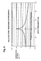
- FIG. 8 is a graphical representation of the frequency response of one embodiment of a rate sensor or gyro employed in the invention.
- FIGS. 9-12 are block diagrams of additional embodiments of inertial rate systems with gyro bias washout modulation and means for processing signals from the rate sensors in accordance with the invention.
- FIGS. 13A-13C and 14 A- 14 B are graphical representations of waveforms in an inertial rate system with gyro bias washout modulation incorporating the invention.
- FIG. 15 is a block diagrams of an additional embodiment of an inertial rate system with gyro bias washout modulation and means for processing signals from the rate sensors in accordance with the invention.
- FIGS. 16-20 are schematic illustrations of additional embodiments of inertial rate systems with gyro bias washout modulation according to the invention.
- two angular rate sensors or gyroscopes X-Gyro and Y-Gyro have their input axes aligned with the x- and y-axes, respectively.
- Input axis modulation or dither introduces an oscillatory rotation about the z-axis which is perpendicular to the input axes.
- the dither oscillation can range in frequency from a few milliHertz to 100 Hertz, or more, depending upon the type of dithering motion employed, with lower frequencies being used for square wave modulation or two-point indexing dither and higher frequencies being used with sinusoidal and other periodic waveforms.
- the magnitude of the dither is typically on the order of a few milliradians to 20 degrees, but it can potentially be as high as ⁇ 90 degrees if input axis reversal is desired.
- the dithering motion causes the input axes of the two rate sensors or gyros to rotate with respect to fixed inertial reference axes, with the change in angular alignment of the sensor axes being equal to the instantaneous angular position of the dither modulation.
- An angular pickoff device (not shown) detects the angular displacement and provides a signal which is used in processing the signals from the rate sensors to remove the effect of the modulation.
- the system includes a mounting base 11 and two angular rate sensors or gyroscopes G x and G y which are mounted on a modulator 12 on the base, with the input axes of the sensors nominally aligned with the x- and y-axes of the base.
- the modulator rotates the sensors about the z-axis which is perpendicular to input axes of the sensors and to the base.
- the rotation is oscillatory or dithering in nature, with a frequency on the order of a few milliHertz to several hundred Hertz and an amplitude on the order of several milliradians to tens of degrees.
- a sensor 13 monitors the position of the modulator and provides a signal corresponding to the instantaneous angular displacement of the modulator and the rate sensors. As discussed more fully hereinafter, that signal allows the system to demodulate or remove the effect of the modulation in connection with the processing of the gyro output signals.
- the modulator can be of suitable known design, including oscillating mechanical flexures or springs, voice-coil actuators, galvanometers, piezoelectric actuators, motors, or MEMS-base structures.
- the amplitude of the modulation should be large enough to provide adequate resolution of the gyro output signals, and the frequency should be higher than the rotation to be measured.
- the frequency of modulation should be high enough so that it is outside the frequency band of the rotation to be measured.
- the frequency For gyrocompassing, where it is assumed that the system is stationary with respect to the earth, the frequency can be much lower.
- the modulator must provide stable motion in the plane of the sensor axes.
- the motion can be of any suitable type, including a simple periodic waveform such as a sine wave or a square wave, or a more complex motion.
- the modulator has been described as a planar structure rotated about an axis perpendicular to its plane, it could be realized in other ways so long as the basic requirement for modulation is met, namely, that of producing a rotation of one or more gyro input axes that results in an oscillation of the orientation of these input axes.
- Modulation sensor 13 can also be of conventional design such as a capacitive sensor, an inductive sensor with a coil and magnet, an optical sensor, or an encoder.
- the rotation of the modulator causes the input axes of the rate sensors or gyros to rotate with respect to the fixed axes of the base, and the difference in alignment between sensor axes and the axes of the base at any given time is equal to the instantaneous angular position of the modulator.
- the modulator rotates the input axes themselves, and there is no spurious rate input.
- the orientation of the input axes is varied in a dithering manner with a relatively rapid, oscillatory motion, and in the absence of other externally applied angular inputs, the rotation of the sensor axes does not produce a rotation rate signal.
- the demodulator output signals can be fed into analog signal processing circuitry for producing an analog output of the applied external rotation ⁇ N , or they can be converted to a digital signal and processed using digital signal processing (DSP) for filtering, compensation of errors, and output.
- DSP digital signal processing
- the outputs of the gyros and the signal conditioning circuit can be in digital form, and the demodulators can be implemented in digital form as well.
- the input axes x′, y′ of the rate sensors or gyros are shown as being rotated by an angle ⁇ m with respect to the fixed reference axes x, y of the base.
- the z-axis is perpendicular to the plane of the figure, and an external rate of rotation ⁇ is applied to the entire system, including the base, about the y-axis.
- the modulator oscillates about the z-axis with an amplitude which is typically on the order of 2 milliradians to 20 degrees or more and a frequency on the order of 0.01 to 20 Hertz, depending upon the type of dither motion to be applied, with higher frequencies of oscillation typically being associated with smaller amplitudes of oscillation.
- Two-point indexing dither square wave in angle with respect to time
- Sensor 13 detects the instantaneous value of ⁇ m and provides a signal which is used in processing the output signals from the gyros. That signal allows the system to compensate for the time-varying input axes of rate sensors G x and G y as well as being used in demodulating the gyro outputs.
- the rate sensors or gyros should have a suitable bandwidth for measurements at the frequency of the input axis modulation, and they should also have low enough noise in the frequency range near the modulation frequency to permit the gyro modulation signals to be adequately resolved.
- each rate sensor or gyro Prior to demodulation, the output of each rate sensor or gyro consists of a combination of the sensor fixed offset and the externally applied angular rate. Since the modulation affects the applied angular rate, but not the fixed offset, the system is able to distinguish between them.
- the signal from the modulation sensor which corresponds to the instantaneous orientation of the axes, is used in conjunction with an input axis demodulator in the processing circuit to remove the effect of the mechanical modulation.
- the bias term B i is not modulated and, therefore is washed out or cancelled, as expected.
- the noise term ⁇ i is not cancelled, and is preferably removed by filtering prior to demodulation. If the noise term is excessive, there will be insufficient resolution of the modulated terms and performance of the sensors may be degraded in, for example, trying to determine heading during an alignment phase.
- Sensitivity to misalignment of the gyro input axes with respect to the plane of the dither motion can become a source of error in bias cancellation.
- a component of the sensor input axes along the dither axis results in some of the dither motion being detected by the gyro.
- This error term can be quite large compared to the modulation signals to be measured. Misalignment often needs to be kept to as little as 10 ⁇ rad, which can be very challenging in a mechanical system.
- the dither rate vector is given by: D d ⁇ (0 0 A ⁇ cos ⁇ t ) T .
- the dither angular velocity may be transformed to the x- and y-axes using the misalignment matrix ⁇ C d b :
- D b ⁇ ⁇ ⁇ C d b ⁇
- D d ⁇ ( cos ⁇ ⁇ ⁇ ⁇ ⁇ ⁇ y sin ⁇ ⁇ ⁇ ⁇ ⁇ ⁇ x ⁇ sin ⁇ ⁇ ⁇ ⁇ ⁇ ⁇ y cos ⁇ ⁇ ⁇ ⁇ ⁇ x ⁇ sin ⁇ ⁇ ⁇ ⁇ ⁇ y 0 cos ⁇ ⁇ ⁇ ⁇ ⁇ ⁇ x - sin ⁇ ⁇ ⁇ ⁇ ⁇ ⁇ x - sin ⁇ ⁇ ⁇ ⁇ ⁇ ⁇ y sin ⁇ ⁇ ⁇ ⁇ ⁇ ⁇ x ⁇ cos ⁇
- modulator 12 is driven by a signal generator 16 which includes an automatic gain control (AGC) circuit.
- AGC automatic gain control
- the output of modulation sensor 13 is processed in a conditioning circuit 17 , and the conditioning circuit provides a feedback signal to the AGC circuit in the signal generator to maintain the amplitude of the modulation at a constant level.
- the externally applied rotation ⁇ is about an axis in the plane of the input axes of the two gyros.
- the outputs of the two gyros are applied to the inputs of a pair of demodulators 18 , 19 , and the output of signal conditioning circuit 17 is applied as a phase reference to the two demodulators.
- the outputs of the demodulators are the signals S x and S y from which the values of applied rotation ⁇ and the angle of orientation ⁇ 0 are determined, and by using equations (1.2), for example, the north component of earth rotation rate ⁇ N can be estimated.
- Output signals S x and S y can be fed to analog signal processing circuitry (not shown) to provide an analog output signal corresponding to the applied external rotation ⁇ , or they can be converted to digital form and processed digitally for filtering, compensation of errors, and output.
- the gyros and the signal conditioning circuit can provide digital outputs, and demodulators 18 , 19 can be digital as well.
- the set of equations in (1.5) represents the mathematical principle of first harmonic bias cancellation in which the misalignment induced errors are demodulated by a particular phase of the dither reference signal (in this example, cosine rectification), whereas the desired earth rate signal is demodulated by the phase of the dither reference signal 90° out-of-phase with respect to the misalignment signal (i.e., sine rectification).
- the first harmonic technique can be used for autonomously calibrating the gyro misalignment angles. This feature is very desirable for autonomous alignment and field calibration of stand-off weapons, among other applications.
- FIG. 5 illustrates an embodiment in which two demodulations (sin ⁇ t and cos ⁇ t) are performed.
- the demodulated outputs provide estimates of the quantities in equations (1.5) and permit determination of both the heading ( ⁇ ) and the misalignment errors ( ⁇ x and ⁇ y).
- two gyros G x and G y are mounted on a modulator 12 that oscillates about an axis substantially perpendicular to the input axes of the two gyros.
- the modulator is driven by a modulation signal generator 16 which controls the amplitude of the modulation by means of a feedback signal from the modulator sensor 13 and signal conditioning circuit 17 .
- the feedback signal is used by the modulation signal generator to adjust the modulation signal to maintain a constant amplitude of modulation.
- Externally applied components of rotation, such as ⁇ N lie in the plane of the modulation.
- Signal conditioning circuit 17 provides sin ⁇ t phase reference signals to demodulators 21 , 23 and cos ⁇ t phase reference signals to demodulators 22 , 24 .
- the output of gyro G y is applied to demodulators 21 , 22
- the output of gyro G x is applied to demodulators 23 , 24 , with the demodulators providing the four signal outputs corresponding of equations (1.5). Additional signal processing can be performed on these signals to compute ⁇ N , heading ⁇ and misalignment errors ⁇ x and ⁇ y. If necessary, adjustments to the phase of the two phase reference signals can be made in the signal conditioning.
- modulator 12 and modulator pickoff 13 are depicted as being external to gyros G x , G y , they can also be integrated into the sensing elements themselves or into the sensing element packages such that only the sensing elements are dithered as opposed to the entire gyro. This can be significant when the size and mass of the total gyro package is significantly greater than the size and mass of either the sensing elements or sensing element packages.
- a system of three independently dithered gyros or angular rate sensors can be assembled using three dithered sensors of the type illustrated.
- Integration of the modulator into the sensing element package or as a part of the sensing element structure is particularly suitable for very small gyro sensing elements such as MEMS devices which are produced from quartz or silicon wafers using micro-electromechanical techniques.
- MEMS devices without built-in modulators which are already in production for a variety of applications could be made suitable for higher accuracy applications by combining them with the bias cancellation techniques of the invention.
- Such a gyro with integrated mechanical modulation can provide improved accuracy by cancelling bias offset without significant cost or size penalties.
- FIG. 6 is similar to the embodiment of FIG. 5 except that the modulator dithers only a single gyro.
- the other features of this embodiment are the same as in the preceding one.
- the second harmonic signals in equations (1.3) are not affected by misalignment of the gyro input axes with respect to the dither rate because in this case the signal of interest is at twice the modulation frequency, i.e., 2 ⁇ .
- FIG. 7 An embodiment utilizing second harmonic demodulation is illustrated FIG. 7 .
- This embodiment is similar to the embodiment of FIG. 4 except that only a single gyro G y is used, and signal processing circuit 17 provides two frequency reference outputs.
- One of those outputs has a frequency of ⁇ /2 ⁇ and is equivalent to the reference signal applied to the demodulators in the embodiment of FIG. 4 . It is applied to the reference input of demodulator 18 .
- the other output has a frequency of ⁇ / ⁇ , which is twice the modulation frequency, and is applied to the reference input of demodulator 19 .
- the output of gyro G y is applied to the signal inputs of both demodulators.
- a modulator feedback signal from sensor 13 and signal conditioning circuit is applied to modulation signal generator 16 for use in controlling the amplitude of the modulation signal.
- Demodulator 18 operates in the same manner as the corresponding demodulator in the embodiment of FIG. 4 .
- Demodulator 19 operates at twice the modulator frequency and converts the gyro output signal into a signal roughly proportional to the values in equations (1.6), i.e., second-order in the modulation amplitude A.
- the second harmonic technique can be enhanced by using two phase references in phase quadrature, e.g., sin 2 ⁇ t in addition to cos 2 ⁇ t. While all of the desired signal may be obtained using one reference, e.g. cos 2 ⁇ t, phase shifts in the system may cause some of the signal to be in phase with the other term, sin 2 ⁇ t.
- the combination of the two second-order demodulation products provides the basis for improved second harmonic bias cancellation.
- the second harmonic technique has the advantage of being insensitive to misalignment, but it also has the disadvantage of much weaker modulation amplitude since it is a second-order effect.
- this disadvantage can be overcome by adapting the dither modulation frequency to the specific frequency response characteristics of the gyro being modulated.
- Some gyros and angular rate sensors do not have constant output sensitivity versus frequency.
- Coriolis vibratory rate sensors such as quartz tuning fork sensors and micromachined silicon inertial sensors often have an increased sensitivity at specific frequencies. This may correspond, for example, to the difference in frequency between the drive mode or Coriolis reference mode and the sense mode of oscillation.
- FIG. 8 illustrates the frequency response of a high Q quartz tuning fork in graphical form.
- the example is for the case of a tuning fork with natural frequency of 11 kHz and Q-factor of 30,000. If such a sensor is modulated or dithered at a frequency of 20 Hz, the second harmonic signal will be amplified by two orders of magnitude relative to the dc response of the fork. The gain is nearly as great between the second and first harmonic signal amplification factors. With this technique, the second harmonic is selectively amplified with a corresponding improvement in resolution of the modulation signal.
- phase shift of the modulated signal will result, depending on the difference in frequency between twice the dither frequency and the peak-response frequency of the tuning fork. This phase shift is approximately 90° when the frequencies are matched but can vary significantly for small mismatches in frequency.
- the use of two demodulators with phase references in phase quadrature improves the performance of the second harmonic technique.
- the total amplitude of response can be made insensitive to small frequency changes by calculating the root sum square (RSS) of the two demodulation products, specifically, ([H 2 ⁇ ⁇ y )]sin 2 ⁇ t> 2 ⁇ and ⁇ [H 2 ⁇ ( ⁇ y )]cos 2 ⁇ t> 2 ⁇ , as shown in FIG. 6 .
- the relative amplitudes of the two demodulation products can be used to adjust the dither frequency to keep it adjusted to one-half of the peak response frequency, thereby maintaining maximum response even if the peak response frequency varies, for example, over temperature.
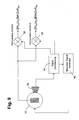
- Gyro G y is mounted on a modulator 12 which oscillates about an axis substantially perpendicular to the input axis of the gyro.
- the modulator is driven by a modulation signal generator 16 which controls the amplitude of the modulation by means of a feedback signal from modulation sensor 13 and signal conditioning circuit 17 .
- the feedback signal is used by the modulator signal generator to adjust the modulation signal to maintain a constant amplitude of modulation.
- the component of externally applied rotation to be measured ⁇ lies in a plane perpendicular to the dither axis of the modulator.
- the signal conditioning circuit provides a first output signal sin 2 ⁇ t which is applied to demodulator 21 as a phase reference and a second output signal cos 2 ⁇ t which is applied to demodulator 22 as a phase reference.
- the gyro output is fed into both of the demodulators to provide the two signal outputs, as shown. Additional signal processing can be performed on these signals to estimate the component of ⁇ parallel to the average orientation of the input axis of the gyro. Two such gyros mounted in a nominally orthogonal relationship as in FIG. 5 , but using second harmonic demodulation can be used to estimate heading ⁇ .
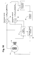
- FIG. 10 is similar to the embodiment of FIG. 9 with the addition of an output signal comparator 26 and a frequency correction circuit 27 .
- the output signals from demodulators 21 , 22 are applied to the comparator, and the output of the comparator is applied to the frequency correction circuit, which applies a correction signal to modulation signal generator 16 .
- the modulation frequency By adjusting the modulation frequency, the ratio of the two output signals can be maintained at a constant value, and the circuit can track changes in the difference frequency between the driven mode of oscillation and the sense mode for a Coriolis vibratory gyro.
- Either first or second harmonic demodulation provides a means to estimate sin ⁇ and cos ⁇ and thereby to estimate the heading angle ⁇ itself, and both types of demodulation can be used for the same gyro to improve the overall accuracy of the sensor or system.
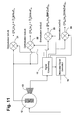
- FIG. 11 An embodiment utilizing both first and second harmonic sensor modulation and demodulation with a single gyro is shown in FIG. 11 . This could also be done with a pair of sensors mounted in a nominally orthogonal relationship, as in the embodiment of FIG. 5 .
- gyro G y is mounted on a modulator 12 which oscillates about an axis substantially perpendicular to the input axes of the two gyros.
- the modulator is driven by a modulation signal generator 16 which receives a feedback signal from modulation sensor 13 and signal conditioning circuit 17 .
- the feedback signal is used by the modulator signal generator to adjust the modulation signal to maintain a constant amplitude of modulation.
- the component of externally applied rotation to be measured ⁇ N once again lies in a plane perpendicular to the dither axis of the modulator.
- the signal conditioning circuit generates four phase reference signals which correspond to sin ⁇ t, cos ⁇ t, sin 2 ⁇ t, and cos 2 ⁇ t, respectively. These signals are applied to the demodulators as phase references, with the sin ⁇ t signal being applied to demodulator 21 , the cos ⁇ t signal being applied to demodulator 22 , the sin 2 ⁇ t signal being applied to demodulator 23 , and the cos 2 ⁇ t signal being applied to demodulator 24 .
- the output of the gyro is fed into all four of the demodulators to provide the four signal outputs. Additional signal processing can be performed on these signals to estimate ⁇ N and ⁇ .
- the output of the single gyro in the embodiment of FIG. 11 can be used for estimating both ⁇ N and ⁇ since the first harmonic demodulation products provide an output proportional to ⁇ N ⁇ cos ⁇ (equations 1.5) for y-axis gyro while the second harmonic demodulation products provide an output proportional to ⁇ N ⁇ sin ⁇ (equations 1.6) for y-axis gyro.
- the amplitude of the dither (A in the above equations) is determined by the modulator signal generator 16 .
- ⁇ N in the locally level coordinate system may also be known.
- a system of three independently dithered gyros or angular rate sensors can be assembled using three dithered sensors as shown here or as in FIGS. 6 and 9 .
- bias washout techniques are readily apparent in that relatively inexpensive gyros or rate sensors can be used in applications typically requiring much more expensive or bulky sensors.
- the invention is particularly suitable for use in gyrocompassing applications where the angular velocity of the earth is used to determine north.
- the apparatus is otherwise stationary, and the externally applied rotation is just the rotation of the earth.
- the latitude can also be determined from the component of the earth's rate as measured by the gyros in the horizontal plane of the locally level system. Adjustment for the effect of the modulation amplitude A can be made in the calibration of the system.
- Second harmonic modulation and demodulation definitely reduces the sensitivity to sensor misalignment, it can result in an inadequate signal-to-noise ratio unless selective amplification of the second harmonic modulation is employed, as described above.
- First harmonic modulation and demodulation will generally have a superior signal-to-noise ratio, but is inherently sensitive to misalignment of the sensors.
- the invention can be adapted to accurately determine the error in phase of the demodulation reference signals, thereby permitting those signals to be controlled for still further reduction in errors resulting from misalignment of the sensors.
- equations (1.5) it is possible to reject errors due to sensor misalignment to the dither modulation by providing the correct phase for demodulation.
- the demodulation waveform with the correct phase is sin ⁇ t.
- the output obtained using this signal for demodulation is not corrupted by errors due to misalignment.
- the waveform in phase quadrature with the correct waveform is given by cos ⁇ t, and the output obtained using this phase reference provides a signal proportional to the misalignment term.
- modulator sensor signals will be subject to phase errors due to phase shifts in electronic circuits or to errors in the modulation sensor itself. Therefore, it may be necessary to apply a correction to the phase of the demodulation signals to obtain the ideal signals represented by sin ⁇ t and cos ⁇ t.
- a phase error of 1° in sin ⁇ t will, for example, allow about 1.75% of the full misalignment rate error signal to be added to the true rate signal. Since the misalignment rate error signal can possibly be quite large relative to the rate signals to be resolved, a phase error of 1° or even significantly less may not be tolerable.
- phase errors can potentially vary with time or as a function of temperature. Therefore, in a sensor or system requiring the maximum possible accuracy and resolution, these errors must be fully accounted for and compensated.
- phase errors One method for controlling these phase errors is to perform an extensive calibration of phase, including effects due to temperature. This calibration is typically performed as a part of the manufacturing process. Once the phase errors have been determined, one of two methods for compensation can be used. In the first of these methods, the effect of the phase error is mathematically removed from the sensor output at some point after demodulation. This can be done by applying the inverse of the misalignment rotation matrix ( ⁇ C d b ) to the demodulation products in equations (1.5).
- ⁇ C d b misalignment rotation matrix
- a phase correction signal is applied to a phase compensation circuit prior to demodulation such as illustrated in the embodiment of FIG. 12 .
- This embodiment is similar to the embodiment of FIG. 6 with the addition of a phase compensation circuit 29 between the output of the gyro and the inputs of the demodulators.
- the phase correction could be performed in the signal conditioning circuit 17 .
- the phase correction to be applied does not need to be static. It can, for example, be responsive to changes in temperature such that the phase compensation takes temperature change into account.
- the phase correction can be controlled by an analog or digital signal provided by the system in which the gyro is used. If the actual phase error is estimated by an algorithm within the system, the updated phase compensation signal can be applied on a continuous basis, accounting for changes in temperature, time and other factors.
- the actual misalignment and phase errors are calculated and suitable compensation is used to correct for these errors, using either of the methods described above.
- the determination of the phase errors is accomplished by applying a dither modulation consisting of two distinct frequency waveforms.
- the desired rate signal derived from each of the two frequency components will be proportional to the angular displacement associated with each of the frequency components.
- the misalignment signals associated with the two frequency components will not be equal, but rather will be proportional to the product of the angular displacement and the frequency.
- the two rate output signals and the two misalignment rate signals are used to compute the actual phase errors and misalignment terms. Correction signals or computations derived from the calculated phase errors are then used to remove the effects of these errors from the system output either before or after demodulation.
- the waveform of one of the two frequency components is approximately a square wave in angle while the other is a sine wave.
- the modulator has sufficient dynamic response to provide a rapid movement approximating the desired square wave motion.
- the modulator cannot change angle instantaneously, so the rise time of the waveform corresponding to the transition from one angular position to the other is finite, although much less than the period of the waveform.
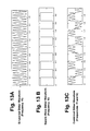
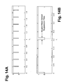
- FIGS. 13A-13C A two frequency waveform of the type discussed above is illustrated in FIGS. 13A-13C , with each waveform being shown separately in FIGS. 13A and 13B and the two being shown in combination in FIG. 13C .
- the relative magnitudes of the angular displacement of the two frequency components are shown as being roughly equal in this example, this is not a requirement.
- the quasi-square wave dither (excluding the transition times) is not subject to rate errors induced by sensor misalignment because it is not changing in angle while at either extreme. Therefore, the output demodulated from this frequency component will be a true rate signal free of misalignment error and, hence, insensitive to phase errors as well.
- the demodulation can be inhibited during these intervals using a demodulation suppression signal as show in FIGS. 14A-14B . This signal guarantees that the large rate signal during the transition times is ignored or “zeroed” out during these intervals. The loss of this fraction of data is taken into account in the system signal-processing algorithm.
- the sine wave dither signal is subject to,error due to misalignment.
- the difference in estimated rate between the two demodulated waveforms (square wave and sign wave) represents the misalignment induced error.
- ⁇ is the difference in measured rate as determined using the two separate dither modulations and demodulations. This difference is R sin ⁇ R square , where “R” refers to the measured angular rate using one or the other of the modulation/demodulation methods.
- M sin is the total misalignment signal for the sine wave dither modulation which can be estimated, via cos ⁇ t demodulation, using equations (1.5) since the effect of small phase errors on the relatively large misalignment induced signal is negligible.
- ⁇ sin This estimate of ⁇ sin can be obtained on a continuous basis.
- the value of ⁇ sin provides the necessary input for real time correction of the phase error using one of the methods given above, thereby minimizing misalignment errors in a first harmonic technique implementation of bias cancellation.
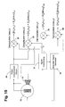
- FIG. 15 illustrates an embodiment which utilizes such two frequency first harmonic demodulation. This system is similar to that of FIG. 11 except that the square wave signal at angular frequency ⁇ 2 is demodulated instead of the second harmonic.
- modulator signal generator 16 generates the sine and square dither waveforms at separated frequencies and applies these two signals to modulator 12 .
- the modulation sensor 13 delivers a dither amplitude signal to the signal conditioning circuit 17 , and that circuit provides a feedback signal to the modulation signal generator 16 , which is used to control the dither amplitudes to predetermined values, with the two frequencies of dither being separately controlled.
- the signal conditioning block also provides four phase reference signals, two of which are in phase quadrature at the sine dither frequency, ⁇ 1 , and two of which in phase quadrature at the square wave dither frequency, ⁇ 2 .
- the initial phase calibration of the system is such that the sine phase references approximately correspond to the proper phase for demodulating the desired rate offset, although they may contain small phase errors.
- the difference in measured rate ⁇ is calculated using the appropriately scaled outputs of demodulators 21 , 23 .
- M sin is calculated using the output of demodulator 22 , also appropriately scaled.
- the appropriate scaling takes into account the amplitude and frequency difference between the two dither signals (square versus sine) as well as a factor of 4/ ⁇ to account for the first harmonic content of a square wave versus a sine wave.
- phase error associated with the ⁇ 1 reference signals is calculated using the equation provided above and compensated using phase compensation circuit 29 or directly in the signal conditioning circuit as a phase adjustment to the reference signals.
- the sine wave dither signal provides uninterrupted output, with no demodulation suppression being required. Therefore, there is no frequency response penalty for this signal as there could be when only square wave dither is used.
- the two frequency method can still be used during an alignment phase to calibrate the phase error for sine demodulation.
- the square wave and sine wave dither can be used one at a time in sequence to accomplish the same thing, i.e., system alignment or initialization.
- the modulator signal generator would have two modes of operation: sine wave and square wave.
- the two dither waveforms can, in this case, be either at the same frequency or at two separate frequencies.
- square wave dither or two-point indexing, can be used by itself as a single frequency of dither.
- Such dithering can, for example, be used in the embodiments of FIGS. 4 and 7 , where the demodulator phase references are adjusted by the signal conditioning electronics circuits 17 and are in phase with the square wave modulation signal.
- This type of dither may be particularly suitable for gyrocompassing applications.
- At least two of the dither modulation axes must be nominally perpendicular.
- a single dither modulator can be used for two of the three gyros.
- the additional features of second harmonic demodulation or two frequency dither, although not shown in this figure, can be added for a pair of gyros sharing a common dither modulator.
- ⁇ is an initial roll angle about the x-axis
- ⁇ D is the vertical (down) component of earth rotation rate at a given latitude
- A is the modulation amplitude
- ⁇ is the dither angular frequency
- B z and ⁇ z are the bias and Gaussian random errors of the Z-gyro, respectively.
- This second dither motion i.e. mechanical modulation for the z-axis gyro, is applied about x-axis.
- the second dither rate vector is given by: D 2 d ⁇ ( A ⁇ cos ⁇ t 0 0) T .
- the first harmonic demodulation result always gives a null value.
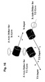
- Equations (2.8) can be called the fundamental equations of the first harmonic bias cancellation technique for the third gyro (for measuring vertical angular rate). This 3-axis IMU configuration is illustrated in FIG. 16 .
- the X and Y1 gyros are dithered about the z-axis, either by a common dither modulator or separate ones.
- the Y2-gyro is initially aligned with input axis parallel to the Y1 gyro, but this gyro is responsible for measuring the vertical component of angular rate. This is made possible by dithering of the Y2 gyro about the X-axis.
- This inertial platform for a first harmonic implementation of bias cancellation for a three-axis IMU is particularly unique in that the three gyros have their input axes nominally in the same plane.
- the x-axis dither of the Y2 gyro permits measurement of the vertical rate component.
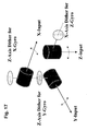
- Equation (2.9) can be called the fundamental equations of the second harmonic bias cancellation technique for the third gyro (for measuring vertical angular rate). Unlike the first harmonic technique, using the second harmonic, the third gyro is aligned vertically and dithered about the x-axis, as can be seen in the embodiment of FIG. 17 .
- Equation (1.5), (1.6), (2.8), and (2.9) provides a set of fundamental equations for the first harmonic technique for bias cancellation or washout for a three-axis gyro IMU (as in the embodiment of FIG.
- a heading can be calculated using the first harmonic technique for signal processing of X-and Y-gyro readouts to obtain a coarse alignment.
- a heading can also be calculated using the second harmonic technique for signal processing of X-and Y-gyro readouts to obtain a coarse alignment.
- Equations (5.2) express a set of 3-axis strapdown gyro outputs using the outputs obtained from the first harmonic bias cancellation technique.
- Equation 5.3 K ⁇ 8A ⁇ 2 (Equation 5.3) as a scale factor
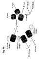
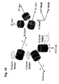
- FIGS. 18 and 19 illustrate six-degree-of-freedom (6DOF) strapdown IMU's utilizing the 1 st and 2 nd harmonic techniques for gyro bias cancellation, respectively.
- 6DOF six-degree-of-freedom
- C n b is the direction cosine matrix from the local-level navigation frame (East-North-Up) to the body frame, with ⁇ ie being the Earth rotation rate and L being the latitude of the alignment location.
- the steady state model can be assumed as in the equations (5.14)-(5.16) above.
- Equation 5 A 2 and A 3 are known via Equation (5.17).
- Equations (5.18) completely determine the body-to-local-level DCM.
- Equations (6.3) become: ⁇ ⁇ x ⁇ - S ⁇ ⁇ [ H ⁇ ⁇ ( ⁇ y ) + D y ] ⁇ cos ⁇ ⁇ ⁇ ⁇ ⁇ t ⁇ ⁇ , ⁇ y ⁇ S ⁇ ⁇ [ H ⁇ ⁇ ( ⁇ x ) + D x ] ⁇ cos ⁇ ⁇ ⁇ ⁇ ⁇ t ⁇ ⁇ , ⁇ z ⁇ S ⁇ ⁇ [ H ⁇ ⁇ ( ⁇ y ⁇ ⁇ 2 ) + ( D 2 b ) y ⁇ ⁇ 2 ] ⁇ cos ⁇ ⁇ ⁇ ⁇ ⁇ t ⁇ ⁇ . ( 6.4 )
- IMU inertial measurement unit
- bias cancellation including means for determining dither misalignment angles.
- the additional features described with reference to 1 and 2 degree-of-freedom embodiments can readily be included in the IMU's described, i.e., selective amplification of the modulation signal using the increased sensitivity at specific frequencies of one or more of the gyros; and estimation of, and compensation for, the phase errors at demodulation, including the use of two frequencies of dither and/or a combination of square wave and sine wave dither waveforms.
- the estimated misalignment angles are mechanically compensated for by use of a tiltable platform, preferably one that is controllable by an electronic signal.
- a tiltable platform preferably one that is controllable by an electronic signal.
- Such a platform preferably mounted between the dither modulator and a given gyro, can be constructed using piezoelectric or other suitable materials, as is well known.
- the effect of misalignment errors can be eliminated in real time using a feedback signal derived from the estimated misalignment angles and driving these angles to a null using the tiltable platform.
- TPI Two-Point Indexing
- 6-DOF six-degree-of-freedom mechanization of a strapdown IMU comprising three gyros and three accelerometers.
- both three-axis sets of gyros and accelerometers are mechanically aligned to a vehicle's right orthogonal body coordinate system, i.e. X-Forward (Toward Bow), Y-Right-Wing (To Starboard), and Z-Down (Toward Keel) coordinate frame.
- ⁇ ( ⁇ x ⁇ y ⁇ z ) [ ⁇ 1 b ⁇ cos ⁇ ⁇ ⁇ + ⁇ 2 b ⁇ sin ⁇ ⁇ ⁇ ⁇ sin ⁇ ⁇ ⁇ + ⁇ 3 b ⁇ sin ⁇ ⁇ ⁇ ⁇ ⁇ cos ⁇ ⁇ ⁇ ⁇ 2 b ⁇ cos ⁇ ⁇ ⁇ - ⁇ 3 b ⁇ sin ⁇ ⁇ ⁇ - ⁇ 1 b ⁇ sin ⁇ ⁇ ⁇ + ⁇ 2 b ⁇ cos ⁇ ⁇ ⁇ ⁇ sin ⁇ ⁇ + ⁇ 3 b ⁇ cos ⁇ ⁇ ⁇ ⁇ ⁇ cos ⁇ ⁇ ⁇ ] . ( 7.3 )
- Tilts can be expressed using small angle approximations as: ⁇ ⁇ ⁇ - ⁇ x , ⁇ ⁇ - ⁇ y ,
- TPI alignment given by equation (7.13) is completely insensitive to any small mis-leveling of the gyro platform. This implies that the TPI method is superior to a conventional north finder or north seeking device. In TPI, only the autonomous gyro bias calibration given by equations (7.14) is affected by misalignment.
- the invention has a number of important features and advantages. By eliminating the effects of bias offset, it makes it possible to use less expensive rate sensors or gyros which are relatively small in size but would otherwise be precluded from use because of their relatively large bias offsets.
- the smaller sensors lend themselves to use with smaller modulators, which provides a compact and relatively inexpensive system with improved accuracy. Fixed bias offsets are eliminated or cancelled without producing a spurious rotation rate signal, and the system can also provide cancellation of residual errors in offset compensation models.
- the smaller sensors can mounted to equally smaller modulators, even modulators contained within the gyro package or made integrally with the sensing element itself. This permits a compact and relatively low cost system design with improved gyro accuracy.
- a full inertial measurement unit with gyro bias cancellation permits self-alignment or gyrocompassing and inertial navigation using sensors that heretofore have not been suitable for such applications.
Abstract
Description
- Continuation-in-Part of Ser. No. 11/072,064, now U.S. Pat. No. 7,191,636. Also based on Provisional Application No. 60/785,911, filed Mar. 24, 2006, the priority of which is also claimed.
- 1. Field of Invention
- This invention pertains generally to inertial measurement, and, more particularly, to an inertial measurement system and method in which the fixed bias offset of rate sensors or gyroscopes is cancelled.
- 2. Related Art
- Angular rate sensors or gyroscopes (gyros) exhibit a non-zero output in the absence of rotation about the input axis. This non-zero output is called bias, and it can cause significant errors in inertial measurements. The magnitude of the error depends upon the type of sensor or gyroscope used. In applications with stringent limits on offset errors, more expensive sensors with very low residual offset errors must generally be used, and those sensors are often relatively large and heavy.
- Heretofore, there have been some attempts to eliminate offset errors by rotating a gyro about the input axis of the sensor, which is bad because it produces a rotation rate signal that must be dealt with. In other systems, horizontal inertial instruments such as gyroscopes and accelerometers have been rotated continuously in carousel fashion about a vertical axis. However, it is not always feasible or even desirable to apply a constant rotation to such instruments.
- With ring laser gyros, certain errors have been eliminated by dithering the sensors about the input axis. However, as noted above, rotating a sensor about its input axis is undesirable because it provides an angular rate input other than the one to be detected.
- In inertial systems of the prior art it is also necessary to rely on complex models to predict variation in offsets over time and due to factors such as temperature. These models can be quite useful in some applications, but it is often necessary to cancel offsets to a higher level of precision than the models can provide.
- It is in general an object of the invention to provide a new and improved system and method for inertial measurement in which bias offset is cancelled.
- Another object of the invention is to provide a system and method of the above character which overcome the limitations and disadvantages of the prior art.
- These and other objects are achieved in accordance with the invention by providing a system having one or more inertial sensors in which one or more of the sensor input axes are modulated in orientation about an axis substantially perpendicular to the input, or sensitive, axis of the sensor and, in some embodiments, by also enhancing the accuracy of such a system to provide improved signal to noise ratio and reduced sensitivity to errors in alignment of the sensor axes to the dither axes.
-
FIG. 1 is a schematic illustration of one embodiment of an inertial rate system with gyro bias washout modulation. -
FIG. 2 is a schematic perspective view of one embodiment of a rate sensor system according to the invention. -
FIG. 3 is a top plan view of the embodiment ofFIG. 1 . -
FIG. 4 is a block diagram of the embodiment ofFIG. 2 with one embodiment of a system for processing signals from the rate sensors in accordance with the invention. -
FIG. 5 is a block diagram of the embodiment ofFIG. 2 with another embodiment of a system for processing signals from the rate sensors in accordance with the invention. -
FIGS. 6 and 7 are block diagrams of additional embodiments of an inertial rate system with gyro bias washout modulation and means for processing signals from the rate sensors in accordance with the invention. -
FIG. 8 is a graphical representation of the frequency response of one embodiment of a rate sensor or gyro employed in the invention. -
FIGS. 9-12 are block diagrams of additional embodiments of inertial rate systems with gyro bias washout modulation and means for processing signals from the rate sensors in accordance with the invention. -
FIGS. 13A-13C and 14A-14B are graphical representations of waveforms in an inertial rate system with gyro bias washout modulation incorporating the invention. -
FIG. 15 is a block diagrams of an additional embodiment of an inertial rate system with gyro bias washout modulation and means for processing signals from the rate sensors in accordance with the invention. -
FIGS. 16-20 are schematic illustrations of additional embodiments of inertial rate systems with gyro bias washout modulation according to the invention. - As illustrated in
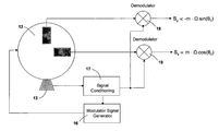
FIG. 1 , two angular rate sensors or gyroscopes X-Gyro and Y-Gyro have their input axes aligned with the x- and y-axes, respectively. Input axis modulation or dither introduces an oscillatory rotation about the z-axis which is perpendicular to the input axes. The dither oscillation can range in frequency from a few milliHertz to 100 Hertz, or more, depending upon the type of dithering motion employed, with lower frequencies being used for square wave modulation or two-point indexing dither and higher frequencies being used with sinusoidal and other periodic waveforms. The magnitude of the dither is typically on the order of a few milliradians to 20 degrees, but it can potentially be as high as ±90 degrees if input axis reversal is desired. - The dithering motion causes the input axes of the two rate sensors or gyros to rotate with respect to fixed inertial reference axes, with the change in angular alignment of the sensor axes being equal to the instantaneous angular position of the dither modulation. An angular pickoff device (not shown) detects the angular displacement and provides a signal which is used in processing the signals from the rate sensors to remove the effect of the modulation.
- In the embodiment of
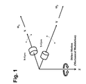
FIG. 2 , the system includes amounting base 11 and two angular rate sensors or gyroscopes Gx and Gy which are mounted on amodulator 12 on the base, with the input axes of the sensors nominally aligned with the x- and y-axes of the base. The modulator rotates the sensors about the z-axis which is perpendicular to input axes of the sensors and to the base. The rotation is oscillatory or dithering in nature, with a frequency on the order of a few milliHertz to several hundred Hertz and an amplitude on the order of several milliradians to tens of degrees. Asensor 13 monitors the position of the modulator and provides a signal corresponding to the instantaneous angular displacement of the modulator and the rate sensors. As discussed more fully hereinafter, that signal allows the system to demodulate or remove the effect of the modulation in connection with the processing of the gyro output signals. - The modulator can be of suitable known design, including oscillating mechanical flexures or springs, voice-coil actuators, galvanometers, piezoelectric actuators, motors, or MEMS-base structures. The amplitude of the modulation should be large enough to provide adequate resolution of the gyro output signals, and the frequency should be higher than the rotation to be measured. For dynamic navigation applications, the frequency of modulation should be high enough so that it is outside the frequency band of the rotation to be measured. For gyrocompassing, where it is assumed that the system is stationary with respect to the earth, the frequency can be much lower. In addition, the modulator must provide stable motion in the plane of the sensor axes. The motion can be of any suitable type, including a simple periodic waveform such as a sine wave or a square wave, or a more complex motion.
- While the modulator has been described as a planar structure rotated about an axis perpendicular to its plane, it could be realized in other ways so long as the basic requirement for modulation is met, namely, that of producing a rotation of one or more gyro input axes that results in an oscillation of the orientation of these input axes.
-
Modulation sensor 13 can also be of conventional design such as a capacitive sensor, an inductive sensor with a coil and magnet, an optical sensor, or an encoder. The rotation of the modulator causes the input axes of the rate sensors or gyros to rotate with respect to the fixed axes of the base, and the difference in alignment between sensor axes and the axes of the base at any given time is equal to the instantaneous angular position of the modulator. Unlike prior art devices which rotate the sensor about the input axis and thereby apply an angular rate input to the sensor, the modulator rotates the input axes themselves, and there is no spurious rate input. The orientation of the input axes is varied in a dithering manner with a relatively rapid, oscillatory motion, and in the absence of other externally applied angular inputs, the rotation of the sensor axes does not produce a rotation rate signal. - The demodulator output signals can be fed into analog signal processing circuitry for producing an analog output of the applied external rotation ΩN, or they can be converted to a digital signal and processed using digital signal processing (DSP) for filtering, compensation of errors, and output. Alternatively, the outputs of the gyros and the signal conditioning circuit can be in digital form, and the demodulators can be implemented in digital form as well.
- In
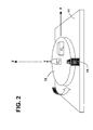
FIG. 3 , the input axes x′, y′ of the rate sensors or gyros are shown as being rotated by an angle θm with respect to the fixed reference axes x, y of the base. The z-axis is perpendicular to the plane of the figure, and an external rate of rotation Ω is applied to the entire system, including the base, about the y-axis. - The modulator oscillates about the z-axis with an amplitude which is typically on the order of 2 milliradians to 20 degrees or more and a frequency on the order of 0.01 to 20 Hertz, depending upon the type of dither motion to be applied, with higher frequencies of oscillation typically being associated with smaller amplitudes of oscillation. Two-point indexing dither (square wave in angle with respect to time) will, for example, make use of low frequency dither and high angular displacement.
-
Sensor 13 detects the instantaneous value of θm and provides a signal which is used in processing the output signals from the gyros. That signal allows the system to compensate for the time-varying input axes of rate sensors Gx and Gy as well as being used in demodulating the gyro outputs. - The rate sensors or gyros should have a suitable bandwidth for measurements at the frequency of the input axis modulation, and they should also have low enough noise in the frequency range near the modulation frequency to permit the gyro modulation signals to be adequately resolved.
- Prior to demodulation, the output of each rate sensor or gyro consists of a combination of the sensor fixed offset and the externally applied angular rate. Since the modulation affects the applied angular rate, but not the fixed offset, the system is able to distinguish between them.
- With the two signals being affected differently by the modulation of the input axis, relatively simple signal processing can be used to separate the two signals, producing a gyro output that is substantially free from the typical effects of gyro offset error or bias. The signal from the modulation sensor, which corresponds to the instantaneous orientation of the axes, is used in conjunction with an input axis demodulator in the processing circuit to remove the effect of the mechanical modulation.
- The outputs of the X and Y gyros on a stationary, leveled plane on the earth can be expressed mathematically, up to the second-order terms, by the following equations:
where Ψ is the true heading of the x-axis gyro; ΩN is the north component of earth rotation rate at given latitude; A is the modulation amplitude; ω is the dither angular frequency (2πf); and Bi and νi are bias and (Gaussian) random errors of the ith-gyro, respectively. - Extracting the fundamental (i.e., first harmonic) and the second harmonic components from equations (1.1) gives separate frequency terms as follows:
First Harmonic:
Second Harmonic: - In equations (1.2) and (1.3), the bias term Bi is not modulated and, therefore is washed out or cancelled, as expected. The noise term νi, however, is not cancelled, and is preferably removed by filtering prior to demodulation. If the noise term is excessive, there will be insufficient resolution of the modulated terms and performance of the sensors may be degraded in, for example, trying to determine heading during an alignment phase.
- Sensitivity to misalignment of the gyro input axes with respect to the plane of the dither motion can become a source of error in bias cancellation. A component of the sensor input axes along the dither axis results in some of the dither motion being detected by the gyro. This error term can be quite large compared to the modulation signals to be measured. Misalignment often needs to be kept to as little as 10 μrad, which can be very challenging in a mechanical system.
- With the mechanical modulation or dither motion about the z-axis in the embodiment of
FIGS. 2 and 3 , the dither rate vector is given by:
D d≡(0 0 Aω cos ωt)T. - Due to possible misalignment angles δθx and δθy about the z-axis with respect to the x- and y-axes, the dither angular velocity may be transformed to the x- and y-axes using the misalignment matrix δCd b:
- Since the dither frequency ω=2πf creates a relatively high angular rate compared to earth rate, the effect of dither misalignment cannot be ignored. Taking the x and y components, we get the misaligned dither rates with respect to x-, y- and z-axes as follows:
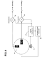
- An embodiment utilizing first harmonic demodulation for bias cancellation is illustrated in the
FIG. 4 . In this embodiment,modulator 12 is driven by asignal generator 16 which includes an automatic gain control (AGC) circuit. The output ofmodulation sensor 13 is processed in aconditioning circuit 17, and the conditioning circuit provides a feedback signal to the AGC circuit in the signal generator to maintain the amplitude of the modulation at a constant level. As inFIG. 2 , the externally applied rotation Ω is about an axis in the plane of the input axes of the two gyros. - The outputs of the two gyros are applied to the inputs of a pair of
demodulators signal conditioning circuit 17 is applied as a phase reference to the two demodulators. The outputs of the demodulators are the signals Sx and Sy from which the values of applied rotation Ω and the angle of orientation θ0 are determined, and by using equations (1.2), for example, the north component of earth rotation rate ΩN can be estimated. - Output signals Sx and Sy can be fed to analog signal processing circuitry (not shown) to provide an analog output signal corresponding to the applied external rotation Ω, or they can be converted to digital form and processed digitally for filtering, compensation of errors, and output. Alternatively, the gyros and the signal conditioning circuit can provide digital outputs, and
demodulators - Signals Sx and Sy are subject to corruption by misalignment induced rate errors if the phase reference is not adequately defined or controlled, and misaligned dither rates can directly disturb the first harmonic terms given by equations (1.2). Combining equations (1.2) with the misalignment dither rates in equations (1.4) with respect to the x- and x-axes, rectifying each component by cos ωt and sin ωt along each axis, and taking their DC components gives the following relationships:
where the bracket < >ω denotes a time-average such that
where φ(t) is a periodic function whose period is given by T0=2nπ/ω. Thus, the set of equations in (1.5) represents the mathematical principle of first harmonic bias cancellation in which the misalignment induced errors are demodulated by a particular phase of the dither reference signal (in this example, cosine rectification), whereas the desired earth rate signal is demodulated by the phase of the dither reference signal 90° out-of-phase with respect to the misalignment signal (i.e., sine rectification). As shown in equations (1.5), the first harmonic technique can be used for autonomously calibrating the gyro misalignment angles. This feature is very desirable for autonomous alignment and field calibration of stand-off weapons, among other applications. - From equations (1.5), it can be seen that an arbitrary phase reference signal will result in an output signal that is a superposition of the desired rate signal and the misalignment induced error signal. In the present invention this is overcome by using a demodulation phase reference adjusted for minimum coupling of the misalignment signal. This means that the phase is adjusted to be in quadrature with respect to the phase that would output the maximum misalignment error signal, i.e., sin ωt demodulation versus cos ωt demodulation.
-
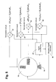
FIG. 5 illustrates an embodiment in which two demodulations (sin ωt and cos ωt) are performed. When properly calibrated, the demodulated outputs provide estimates of the quantities in equations (1.5) and permit determination of both the heading (Ψ) and the misalignment errors (δθx and δθy). - As illustrated in
FIG. 5 , two gyros Gx and Gy are mounted on amodulator 12 that oscillates about an axis substantially perpendicular to the input axes of the two gyros. The modulator is driven by amodulation signal generator 16 which controls the amplitude of the modulation by means of a feedback signal from themodulator sensor 13 andsignal conditioning circuit 17. The feedback signal is used by the modulation signal generator to adjust the modulation signal to maintain a constant amplitude of modulation. Externally applied components of rotation, such as ΩN, lie in the plane of the modulation. -
Signal conditioning circuit 17 provides sin ωt phase reference signals todemodulators demodulators demodulators demodulators - Although the
modulator 12 andmodulator pickoff 13 are depicted as being external to gyros Gx, Gy, they can also be integrated into the sensing elements themselves or into the sensing element packages such that only the sensing elements are dithered as opposed to the entire gyro. This can be significant when the size and mass of the total gyro package is significantly greater than the size and mass of either the sensing elements or sensing element packages. A system of three independently dithered gyros or angular rate sensors can be assembled using three dithered sensors of the type illustrated. Integration of the modulator into the sensing element package or as a part of the sensing element structure is particularly suitable for very small gyro sensing elements such as MEMS devices which are produced from quartz or silicon wafers using micro-electromechanical techniques. MEMS devices without built-in modulators which are already in production for a variety of applications could be made suitable for higher accuracy applications by combining them with the bias cancellation techniques of the invention. Such a gyro with integrated mechanical modulation can provide improved accuracy by cancelling bias offset without significant cost or size penalties. - The embodiment of
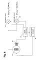
FIG. 6 is similar to the embodiment ofFIG. 5 except that the modulator dithers only a single gyro. The other features of this embodiment are the same as in the preceding one. - Unlike the first harmonic signals, the second harmonic signals in equations (1.3) are not affected by misalignment of the gyro input axes with respect to the dither rate because in this case the signal of interest is at twice the modulation frequency, i.e., 2ω. The second harmonic terms demodulated by cos(2ωt) are:
and the dc component of these are: - The response of the gyros at twice the dither frequency may not be in-phase with respect to the cos(2ωt) demodulation reference signal. This may be caused by changes in the gyro phase response at the frequency f=ω/π and is discussed further below.
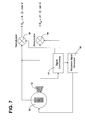
- An embodiment utilizing second harmonic demodulation is illustrated
FIG. 7 . This embodiment is similar to the embodiment ofFIG. 4 except that only a single gyro Gy is used, andsignal processing circuit 17 provides two frequency reference outputs. One of those outputs has a frequency of ω/2π and is equivalent to the reference signal applied to the demodulators in the embodiment ofFIG. 4 . It is applied to the reference input ofdemodulator 18. The other output has a frequency of ω/π, which is twice the modulation frequency, and is applied to the reference input ofdemodulator 19. The output of gyro Gy is applied to the signal inputs of both demodulators. As in the embodiment of Figure, a modulator feedback signal fromsensor 13 and signal conditioning circuit is applied tomodulation signal generator 16 for use in controlling the amplitude of the modulation signal. -
Demodulator 18 operates in the same manner as the corresponding demodulator in the embodiment ofFIG. 4 .Demodulator 19 operates at twice the modulator frequency and converts the gyro output signal into a signal roughly proportional to the values in equations (1.6), i.e., second-order in the modulation amplitude A. - As in the case of first harmonic demodulation, the second harmonic technique can be enhanced by using two phase references in phase quadrature, e.g., sin 2ωt in addition to cos 2ωt. While all of the desired signal may be obtained using one reference, e.g. cos 2ωt, phase shifts in the system may cause some of the signal to be in phase with the other term, sin 2ωt.
- The combination of the two second-order demodulation products provides the basis for improved second harmonic bias cancellation. The second harmonic technique has the advantage of being insensitive to misalignment, but it also has the disadvantage of much weaker modulation amplitude since it is a second-order effect. However, this disadvantage can be overcome by adapting the dither modulation frequency to the specific frequency response characteristics of the gyro being modulated. Some gyros and angular rate sensors do not have constant output sensitivity versus frequency. For example, Coriolis vibratory rate sensors such as quartz tuning fork sensors and micromachined silicon inertial sensors often have an increased sensitivity at specific frequencies. This may correspond, for example, to the difference in frequency between the drive mode or Coriolis reference mode and the sense mode of oscillation.
-
FIG. 8 illustrates the frequency response of a high Q quartz tuning fork in graphical form. The example is for the case of a tuning fork with natural frequency of 11 kHz and Q-factor of 30,000. If such a sensor is modulated or dithered at a frequency of 20 Hz, the second harmonic signal will be amplified by two orders of magnitude relative to the dc response of the fork. The gain is nearly as great between the second and first harmonic signal amplification factors. With this technique, the second harmonic is selectively amplified with a corresponding improvement in resolution of the modulation signal. - Since this type of amplification arises due to the resonant characteristics of the sense mode of the tuning fork, a variable phase shift of the modulated signal will result, depending on the difference in frequency between twice the dither frequency and the peak-response frequency of the tuning fork. This phase shift is approximately 90° when the frequencies are matched but can vary significantly for small mismatches in frequency.
- As mentioned above, the use of two demodulators with phase references in phase quadrature (e.g., sin 2ωt and cos 2ωt) improves the performance of the second harmonic technique. The total amplitude of response can be made insensitive to small frequency changes by calculating the root sum square (RSS) of the two demodulation products, specifically, ([H2ω<ωy)]sin 2ωt>2ω and <[H2ω(ωy)]cos 2ωt>2ω, as shown in
FIG. 6 . - In addition, the relative amplitudes of the two demodulation products can be used to adjust the dither frequency to keep it adjusted to one-half of the peak response frequency, thereby maintaining maximum response even if the peak response frequency varies, for example, over temperature.
- An embodiment with improved second harmonic sensor modulation and demodulation with a single gyro is shown in
FIG. 9 . Gyro Gy is mounted on amodulator 12 which oscillates about an axis substantially perpendicular to the input axis of the gyro. The modulator is driven by amodulation signal generator 16 which controls the amplitude of the modulation by means of a feedback signal frommodulation sensor 13 andsignal conditioning circuit 17. The feedback signal is used by the modulator signal generator to adjust the modulation signal to maintain a constant amplitude of modulation. The component of externally applied rotation to be measured Ω lies in a plane perpendicular to the dither axis of the modulator. - The signal conditioning circuit provides a first output signal sin 2ωt which is applied to
demodulator 21 as a phase reference and a second output signal cos 2ωt which is applied todemodulator 22 as a phase reference. The gyro output is fed into both of the demodulators to provide the two signal outputs, as shown. Additional signal processing can be performed on these signals to estimate the component of Ω parallel to the average orientation of the input axis of the gyro. Two such gyros mounted in a nominally orthogonal relationship as inFIG. 5 , but using second harmonic demodulation can be used to estimate heading Ψ. - The embodiment
FIG. 10 is similar to the embodiment ofFIG. 9 with the addition of anoutput signal comparator 26 and afrequency correction circuit 27. The output signals fromdemodulators modulation signal generator 16. By adjusting the modulation frequency, the ratio of the two output signals can be maintained at a constant value, and the circuit can track changes in the difference frequency between the driven mode of oscillation and the sense mode for a Coriolis vibratory gyro. - Either first or second harmonic demodulation provides a means to estimate sin Ψ and cos Ψ and thereby to estimate the heading angle Ψ itself, and both types of demodulation can be used for the same gyro to improve the overall accuracy of the sensor or system.
- An embodiment utilizing both first and second harmonic sensor modulation and demodulation with a single gyro is shown in
FIG. 11 . This could also be done with a pair of sensors mounted in a nominally orthogonal relationship, as in the embodiment ofFIG. 5 . As in the other embodiments, gyro Gy is mounted on amodulator 12 which oscillates about an axis substantially perpendicular to the input axes of the two gyros. The modulator is driven by amodulation signal generator 16 which receives a feedback signal frommodulation sensor 13 andsignal conditioning circuit 17. The feedback signal is used by the modulator signal generator to adjust the modulation signal to maintain a constant amplitude of modulation. The component of externally applied rotation to be measured ΩN once again lies in a plane perpendicular to the dither axis of the modulator. - In this embodiment, the signal conditioning circuit generates four phase reference signals which correspond to sin ωt, cos ωt, sin 2ωt, and cos 2ωt, respectively. These signals are applied to the demodulators as phase references, with the sin ωt signal being applied to
demodulator 21, the cos ωt signal being applied todemodulator 22, the sin 2ωt signal being applied todemodulator 23, and the cos 2ωt signal being applied todemodulator 24. The output of the gyro is fed into all four of the demodulators to provide the four signal outputs. Additional signal processing can be performed on these signals to estimate ΩN and Ψ. - The output of the single gyro in the embodiment of
FIG. 11 can be used for estimating both ΩN and Ψ since the first harmonic demodulation products provide an output proportional to ΩN·cos Ψ (equations 1.5) for y-axis gyro while the second harmonic demodulation products provide an output proportional to ΩN·sin Ψ (equations 1.6) for y-axis gyro. The amplitude of the dither (A in the above equations) is determined by themodulator signal generator 16. In the case of gyrocompassing, ΩN in the locally level coordinate system may also be known. - A system of three independently dithered gyros or angular rate sensors can be assembled using three dithered sensors as shown here or as in
FIGS. 6 and 9 . - The value of such bias washout techniques is readily apparent in that relatively inexpensive gyros or rate sensors can be used in applications typically requiring much more expensive or bulky sensors.
- The invention is particularly suitable for use in gyrocompassing applications where the angular velocity of the earth is used to determine north. In such applications, the apparatus is otherwise stationary, and the externally applied rotation is just the rotation of the earth. If the system is locally level, or if the inclination of the system is known by the use of accelerometers, the latitude can also be determined from the component of the earth's rate as measured by the gyros in the horizontal plane of the locally level system. Adjustment for the effect of the modulation amplitude A can be made in the calibration of the system.
- As noted above, two key factors in bias cancellation utilizing the techniques disclosed herein are an adequate signal-to-noise ratio and a reduced sensitivity to misalignment of the sensors relative to the applied dither. While second harmonic modulation and demodulation definitely reduces the sensitivity to sensor misalignment, it can result in an inadequate signal-to-noise ratio unless selective amplification of the second harmonic modulation is employed, as described above. First harmonic modulation and demodulation will generally have a superior signal-to-noise ratio, but is inherently sensitive to misalignment of the sensors.
- As discussed more fully hereinafter, the invention can be adapted to accurately determine the error in phase of the demodulation reference signals, thereby permitting those signals to be controlled for still further reduction in errors resulting from misalignment of the sensors.
- As the analysis leading to equations (1.5) shows, it is possible to reject errors due to sensor misalignment to the dither modulation by providing the correct phase for demodulation. In equations (1.5), the demodulation waveform with the correct phase is sin ωt. The output obtained using this signal for demodulation is not corrupted by errors due to misalignment. The waveform in phase quadrature with the correct waveform is given by cos ωt, and the output obtained using this phase reference provides a signal proportional to the misalignment term.
- In practical systems, modulator sensor signals will be subject to phase errors due to phase shifts in electronic circuits or to errors in the modulation sensor itself. Therefore, it may be necessary to apply a correction to the phase of the demodulation signals to obtain the ideal signals represented by sin ωt and cos ωt. A phase error of 1° in sin ωt will, for example, allow about 1.75% of the full misalignment rate error signal to be added to the true rate signal. Since the misalignment rate error signal can possibly be quite large relative to the rate signals to be resolved, a phase error of 1° or even significantly less may not be tolerable.
- To further complicate the calibration of the system, the phase errors can potentially vary with time or as a function of temperature. Therefore, in a sensor or system requiring the maximum possible accuracy and resolution, these errors must be fully accounted for and compensated.
- One method for controlling these phase errors is to perform an extensive calibration of phase, including effects due to temperature. This calibration is typically performed as a part of the manufacturing process. Once the phase errors have been determined, one of two methods for compensation can be used. In the first of these methods, the effect of the phase error is mathematically removed from the sensor output at some point after demodulation. This can be done by applying the inverse of the misalignment rotation matrix (δCd b) to the demodulation products in equations (1.5).
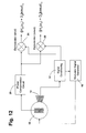
- In the second of these methods, a phase correction signal is applied to a phase compensation circuit prior to demodulation such as illustrated in the embodiment of
FIG. 12 . This embodiment is similar to the embodiment ofFIG. 6 with the addition of aphase compensation circuit 29 between the output of the gyro and the inputs of the demodulators. Alternatively, the phase correction could be performed in thesignal conditioning circuit 17. The phase correction to be applied does not need to be static. It can, for example, be responsive to changes in temperature such that the phase compensation takes temperature change into account. Furthermore, the phase correction can be controlled by an analog or digital signal provided by the system in which the gyro is used. If the actual phase error is estimated by an algorithm within the system, the updated phase compensation signal can be applied on a continuous basis, accounting for changes in temperature, time and other factors. - In one embodiment of the invention, the actual misalignment and phase errors are calculated and suitable compensation is used to correct for these errors, using either of the methods described above. The determination of the phase errors is accomplished by applying a dither modulation consisting of two distinct frequency waveforms.
- When two distinct frequencies are used in a first harmonic modulation waveform, the desired rate signal derived from each of the two frequency components will be proportional to the angular displacement associated with each of the frequency components. However, the misalignment signals associated with the two frequency components will not be equal, but rather will be proportional to the product of the angular displacement and the frequency. The two rate output signals and the two misalignment rate signals are used to compute the actual phase errors and misalignment terms. Correction signals or computations derived from the calculated phase errors are then used to remove the effects of these errors from the system output either before or after demodulation.
- In a preferred embodiment of a sensor system with phase error calculation and compensation as described above, the waveform of one of the two frequency components is approximately a square wave in angle while the other is a sine wave. In this case, the modulator has sufficient dynamic response to provide a rapid movement approximating the desired square wave motion. Of course, the modulator cannot change angle instantaneously, so the rise time of the waveform corresponding to the transition from one angular position to the other is finite, although much less than the period of the waveform.
- A two frequency waveform of the type discussed above is illustrated in
FIGS. 13A-13C , with each waveform being shown separately inFIGS. 13A and 13B and the two being shown in combination inFIG. 13C . Although the relative magnitudes of the angular displacement of the two frequency components are shown as being roughly equal in this example, this is not a requirement. - One advantage of this type of two-frequency dither modulation is that the two waveforms perform complementary functions. The quasi-square wave dither (excluding the transition times) is not subject to rate errors induced by sensor misalignment because it is not changing in angle while at either extreme. Therefore, the output demodulated from this frequency component will be a true rate signal free of misalignment error and, hence, insensitive to phase errors as well. In order to exclude from the demodulation the very large rate signals that occur during the transition times, the demodulation can be inhibited during these intervals using a demodulation suppression signal as show in
FIGS. 14A-14B . This signal guarantees that the large rate signal during the transition times is ignored or “zeroed” out during these intervals. The loss of this fraction of data is taken into account in the system signal-processing algorithm. - The sine wave dither signal, on the other hand, is subject to,error due to misalignment. The difference in estimated rate between the two demodulated waveforms (square wave and sign wave) represents the misalignment induced error. The phase error associated with the sine wave demodulation, αsin, is given by:
αsin=tan−1(Δ/M sin), - where Δ is the difference in measured rate as determined using the two separate dither modulations and demodulations. This difference is Rsin−Rsquare, where “R” refers to the measured angular rate using one or the other of the modulation/demodulation methods. Msin is the total misalignment signal for the sine wave dither modulation which can be estimated, via cos ωt demodulation, using equations (1.5) since the effect of small phase errors on the relatively large misalignment induced signal is negligible.
- This estimate of αsin can be obtained on a continuous basis. The value of αsin provides the necessary input for real time correction of the phase error using one of the methods given above, thereby minimizing misalignment errors in a first harmonic technique implementation of bias cancellation.
-
FIG. 15 illustrates an embodiment which utilizes such two frequency first harmonic demodulation. This system is similar to that ofFIG. 11 except that the square wave signal at angular frequency ω2 is demodulated instead of the second harmonic. - In the embodiment of
FIG. 15 ,modulator signal generator 16 generates the sine and square dither waveforms at separated frequencies and applies these two signals tomodulator 12. Themodulation sensor 13 delivers a dither amplitude signal to thesignal conditioning circuit 17, and that circuit provides a feedback signal to themodulation signal generator 16, which is used to control the dither amplitudes to predetermined values, with the two frequencies of dither being separately controlled. The signal conditioning block also provides four phase reference signals, two of which are in phase quadrature at the sine dither frequency, ω1, and two of which in phase quadrature at the square wave dither frequency, ω2. The initial phase calibration of the system is such that the sine phase references approximately correspond to the proper phase for demodulating the desired rate offset, although they may contain small phase errors. The difference in measured rate Δ is calculated using the appropriately scaled outputs ofdemodulators demodulator 22, also appropriately scaled. The appropriate scaling takes into account the amplitude and frequency difference between the two dither signals (square versus sine) as well as a factor of 4/π to account for the first harmonic content of a square wave versus a sine wave. - The phase error associated with the ω1 reference signals is calculated using the equation provided above and compensated using
phase compensation circuit 29 or directly in the signal conditioning circuit as a phase adjustment to the reference signals. - The sine wave dither signal provides uninterrupted output, with no demodulation suppression being required. Therefore, there is no frequency response penalty for this signal as there could be when only square wave dither is used.
- If a single frequency of dither is required for some applications, the two frequency method can still be used during an alignment phase to calibrate the phase error for sine demodulation. Alternatively, the square wave and sine wave dither can be used one at a time in sequence to accomplish the same thing, i.e., system alignment or initialization. In this case it is possible to use a single pair of demodulators that are capable of operating at either of the two frequencies, with the phase reference signal being switched between sin ω1t and sin ω2t and between cos ω1t and cos ω2t for the two demodulators. Likewise, the modulator signal generator would have two modes of operation: sine wave and square wave. The two dither waveforms can, in this case, be either at the same frequency or at two separate frequencies.
- If the effect of rapid transitions on system performance can be ignored, square wave dither, or two-point indexing, can be used by itself as a single frequency of dither. Such dithering can, for example, be used in the embodiments of
FIGS. 4 and 7 , where the demodulator phase references are adjusted by the signalconditioning electronics circuits 17 and are in phase with the square wave modulation signal. This type of dither may be particularly suitable for gyrocompassing applications. - To provide a full three degree-of-freedom (3DOF) system of gyros with bias cancellation, at least two of the dither modulation axes must be nominally perpendicular.
- As in the embodiment of
FIG. 5 , a single dither modulator can be used for two of the three gyros. The additional features of second harmonic demodulation or two frequency dither, although not shown in this figure, can be added for a pair of gyros sharing a common dither modulator. - For the third gyro of a 3DOF gyro Inertial Measurement Unit (IMU), it is necessary to apply a dither modulation to the Z-axis gyro measuring a vertical angular rate. Assuming the dither rate is applied about the X-axis (roll), then, up to the second-order terms, the Z-axis gyro output normal to a stationary leveled plane on the earth is given by the following equation:
- where φ is an initial roll angle about the x-axis; ΩD is the vertical (down) component of earth rotation rate at a given latitude; A is the modulation amplitude; ω is the dither angular frequency; and Bz and νz are the bias and Gaussian random errors of the Z-gyro, respectively. Extracting the first and second harmonic components from equations (2.1), yields the first and second harmonic terms of ωx and ωy as follows:
H ω(ωz)=−ΩD A sin φsin ωt, (2.2)
- This second dither motion, i.e. mechanical modulation for the z-axis gyro, is applied about x-axis. The second dither rate vector is given by:
D 2 d≡(A ωcos ωt 0 0)T. - Then, due to possible misalignment angles δθz and δθy about the x-axis with respect to the z- and y-axes, respectively, the dither rates can be transformed to the x-, y- and z-axes through the misalignment matrix δQd b:
- Then, the second component of D2 b measured by the Z-axis gyro is given by:
(D 2 b)z=−sin δθy Aω cos ωt - Then, applying the first harmonic technique for bias cancellation gives:
- In Equation (2.4), however, the first harmonic term corresponding to the desired rate signal is not observable, i.e., it is zero if φ=0. In other words, if the z-axis gyro input axis is vertical, the first harmonic demodulation result always gives a null value. This singularity problem can be resolved by letting φ→φ+π/2, i.e., Z→Y2 (as gyro input-axis), as illustrated in
FIG. 11 . When this is done,
ωy2=−ΩD sin(φ+A sin ωt)+B y2+νy2, (2.5)
and
H ω(ωy2)=−ΩD A cos φsin ωt. (2.6) - The second component of D2 b measured by Y2-gyro is given by:
(D 2 b)y2=cos δθy sin δθz Aω cos ωt (2.7) - Finally,
- Equations (2.8) can be called the fundamental equations of the first harmonic bias cancellation technique for the third gyro (for measuring vertical angular rate). This 3-axis IMU configuration is illustrated in
FIG. 16 . - In this embodiment, the X and Y1 gyros are dithered about the z-axis, either by a common dither modulator or separate ones. The Y2-gyro is initially aligned with input axis parallel to the Y1 gyro, but this gyro is responsible for measuring the vertical component of angular rate. This is made possible by dithering of the Y2 gyro about the X-axis. This inertial platform for a first harmonic implementation of bias cancellation for a three-axis IMU is particularly unique in that the three gyros have their input axes nominally in the same plane. The x-axis dither of the Y2 gyro permits measurement of the vertical rate component.
- The foregoing analysis considered only the first harmonic technique for bias cancellation. For the second harmonic technique as applied to the vertical gyro, it follows from Equation (2.3) that
- Equation (2.9) can be called the fundamental equations of the second harmonic bias cancellation technique for the third gyro (for measuring vertical angular rate). Unlike the first harmonic technique, using the second harmonic, the third gyro is aligned vertically and dithered about the x-axis, as can be seen in the embodiment of
FIG. 17 . - Summarizing the equations derived above as Equations (1.5), (1.6), (2.8), and (2.9) provides a set of fundamental equations for the first harmonic technique for bias cancellation or washout for a three-axis gyro IMU (as in the embodiment of
FIG. 16 ): - And for the second harmonic technique for a three-axis gyro IMU as in the embodiment of
FIG. 17 :
where - From the second and fourth equations in (3.1), it follows that
- Thus, a heading can be calculated using the first harmonic technique for signal processing of X-and Y-gyro readouts to obtain a coarse alignment.
- Similarly, it follows from Equations (3.2) that
- So, a heading can also be calculated using the second harmonic technique for signal processing of X-and Y-gyro readouts to obtain a coarse alignment.
- From Equations (3.1), and setting K≡2A−1 (Equation 5.1) as a scale factor, it is possible to reconstruct strapdown gyro readouts of X (forward), Y (right-wing), and Z (down) gyro axes as illustrated in
FIG. 1 such that - Equations (5.2) express a set of 3-axis strapdown gyro outputs using the outputs obtained from the first harmonic bias cancellation technique. Similarly, from equations (3.2), and defining K≡8A−2 (Equation 5.3) as a scale factor, it is also possible to reconstruct the strapdown gyro readouts of X (forward), Y (right-wing), and Z (down) gyro axes using the second harmonic bias cancellation technique such that:
- Now, performing angular measurements per Equations (5.2) or (5.4), angular rate measurement can be defined in a new frame [X′ (forward), Y′ (left-wing), and Z′ (up-canopy)] (a common body frame) such that
ωb≡(ω1 bω2 bω3 b)T=({circumflex over (ω)}x−{circumflex over (ω)}y−{circumflex over (ω)}z)T (5.5) - Then, assuming specific force measurements in the same X′-Y′-Z′ body frame by a set of 3-axis strapdown accelerometers, we have
ƒb≡(ƒ1 bƒ2 bƒ3 b)T (5.6) -
FIGS. 18 and 19 illustrate six-degree-of-freedom (6DOF) strapdown IMU's utilizing the 1st and 2nd harmonic techniques for gyro bias cancellation, respectively. A triad of three-axis accelerometers is contained in the IMU whose body frame coincides with the accelerometer frame. Now, - where Cn b is the direction cosine matrix from the local-level navigation frame (East-North-Up) to the body frame, with Ωie being the Earth rotation rate and L being the latitude of the alignment location. Now expressing the above equations using decoupled forms for each body axis,
- Normalizing the left hand side of the previous equation gives
- Namely, we may define the measurement model:
Z k j ≡Hx k j+νk j (5.9) - where
- at the k-th time step and for the j-th body axis (j=1, 2, 3). Finally, we also have a state space model:
X k+1 j=Φk+1,k x k j (5.14) - where
- Assuming the strapdown platform is stationary during the alignment, the steady state model can be assumed as in the equations (5.14)-(5.16) above. Through a Kalman filtering process, the state vector
- is estimated and updated at time step k. Then, since the direction cosine matrix (DCM) is orthogonal, namely,
C b n(Cb n)T =C b n(C b n)−1 =I, (I=Identity Matrix) - The coefficients of the first row of the DCM are then calculated by
C 11 =C 22 C 33 −C 32 C 23,
C 12 =C 31 C 23 −C 21 C 33, (5.18)
C13 =C 21 C 32 −C 31 C 22 - To see this is so, let
- Then we have
A 1 =A 2 ×A 3, - where A2 and A3 are known via Equation (5.17). Henceforth, Equations (5.18) completely determine the body-to-local-level DCM. Now the Euler angles are derived from the body-to-local-level DCM,
Roll: φ=a tan(C 32 /C 33);
Pitch: θ=a tan(C 31 /√{square root over (C32 2+C33 2)}); (5.19)
Heading: Ψ=a tan(C 11 /C 21). - In addition, the desired orthogonality of the body-to-local-level DCM−Cb n is always maintained by Equations (5.18).
- Misalignment estimation (for purposes of calibration) using the first harmonic technique for bias cancellation is given by Equations (1.5) and (2.8), or by Equations (3.1) such that
- Defining a scale factor S
S=2A −1ω−1, (6.2) - from equations (6.1) and (6.2) it follows that
- Assume that the misalignment angles are small enough, i.e. cos δθx=cos δθy=cos δθz≈1 and sin δθx≈δθx; sin δθy≈δθy; sin δθz≈δθz.
- Then, Equations (6.3) become:
- Thus, a three degree-of-freedom inertial measurement unit (IMU) with bias cancellation, including means for determining dither misalignment angles, has been provided. The additional features described with reference to 1 and 2 degree-of-freedom embodiments can readily be included in the IMU's described, i.e., selective amplification of the modulation signal using the increased sensitivity at specific frequencies of one or more of the gyros; and estimation of, and compensation for, the phase errors at demodulation, including the use of two frequencies of dither and/or a combination of square wave and sine wave dither waveforms.
- In yet another embodiment of the invention, either in the form of a single sensor or as a system of sensors, the estimated misalignment angles, as in equations (6.4), are mechanically compensated for by use of a tiltable platform, preferably one that is controllable by an electronic signal. Such a platform, preferably mounted between the dither modulator and a given gyro, can be constructed using piezoelectric or other suitable materials, as is well known. The effect of misalignment errors can be eliminated in real time using a feedback signal derived from the estimated misalignment angles and driving these angles to a null using the tiltable platform.
- Two-Point Indexing (TPI), or square-wave modulation, can be considered in a six-degree-of-freedom (6-DOF) mechanization of a strapdown IMU comprising three gyros and three accelerometers. In the embodiment illustrated in
FIG. 20 , both three-axis sets of gyros and accelerometers are mechanically aligned to a vehicle's right orthogonal body coordinate system, i.e. X-Forward (Toward Bow), Y-Right-Wing (To Starboard), and Z-Down (Toward Keel) coordinate frame. - The 3-axis accelerometer readout (ƒx b ƒy b ƒz b) may give pitch (θ) and roll (φ) Euler angles of the vehicle's attitude with respect to the local vertical coordinate frame, i.e. north, east, down (NED) such that
- From equation (7.1), the leveling direction cosine matrix (DCM) from the body to the locally leveled platform (not identical with NED-frame) can be calculated such that
- Let ωib b≡(ω1 b ω2 b ω3 b)T be angular rate vector consisting of the output of the strapdown 3-axis gyro unit. Now, we obtain the leveled gyro readout by matrix (7.2) such that
- Assume that each gyro has a large bias but low noise (≦10−3 deg/√{square root over (hr)}). Now, the stationary and leveled X- and Y- gyro components in (7.3) are also modeled by
- where
-
- Ψ=vehicle's heading,
- Ω=earth rate,
- L=vehicle's latitude
- Bi=i−gyro fixed bias,
- νi=i−gyro zero−mean noise,
- Tilts can be expressed using small angle approximations as:
- so that
- Substituting equations (7.5) into equations (7.4), and considering the X-and Y- readouts, we have
- Taking a time average of (7.6) such that
- Assuming that the zero-mean gyro noise becomes negligible through the average-time T, we have
- Now, as illustrated in
FIG. 20 , applying an indexing motion about vertical Z-axis and rotating the two-axis, leveled gyro unit counter-clockwise on the level-plane about the local vertical down axis by the rotation angle, Δ, we have - Next, rotate the gyro unit clockwise on the level-plane about the local vertical down axis by the rotation angle 2Δ, we have
- Subtracting equations (7.9) from equations (7.8), we have
- Thus, in (7.10), the misalignment terms of vertical earth rate disappear as well as fixed biases, so that
- Assume sin Δ≠0, i.e., Δ≠nπ, where n is an integer, so that from equations (7.11) it follows that
- Solving equation (7.12) for Ψ, we obtain
- Finally, using this value of Ψ in equations (7.7), the sum of the gyro bias and the misalignment projection of the vertical earth rate is given by
- We first need the value of latitude (L) to estimate the gyro bias. In the TPI method, X- and Y-misalignments affect the bias estimation by giving rise to the following bias estimation errors:
- It is well known that
- where βx and βy are X- and Y-accelerometer bias errors, respectively, and g is the earth's gravity. In Walnut Creek, Calif., (Latitude=37.9272 °N), and assuming δθx=δθy=1 [mrad] (leveled by 1-mg-grade accelerometer unit), Equations (7.14) give bias estimation errors of:
- Unlike conventional north finder where the heading is derived by
- the TPI alignment given by equation (7.13) is completely insensitive to any small mis-leveling of the gyro platform. This implies that the TPI method is superior to a conventional north finder or north seeking device. In TPI, only the autonomous gyro bias calibration given by equations (7.14) is affected by misalignment.
- The invention has a number of important features and advantages. By eliminating the effects of bias offset, it makes it possible to use less expensive rate sensors or gyros which are relatively small in size but would otherwise be precluded from use because of their relatively large bias offsets. The smaller sensors lend themselves to use with smaller modulators, which provides a compact and relatively inexpensive system with improved accuracy. Fixed bias offsets are eliminated or cancelled without producing a spurious rotation rate signal, and the system can also provide cancellation of residual errors in offset compensation models.
- The smaller sensors can mounted to equally smaller modulators, even modulators contained within the gyro package or made integrally with the sensing element itself. This permits a compact and relatively low cost system design with improved gyro accuracy. A full inertial measurement unit with gyro bias cancellation permits self-alignment or gyrocompassing and inertial navigation using sensors that heretofore have not been suitable for such applications.
- It is apparent from the foregoing that a new and improved improved inertial sensor, inertial measurement system, and method have been provided. While only certain presently preferred embodiments have been described in detail, as will be apparent to those familiar with the art, certain changes and modifications can be made without departing from the scope of the invention as defined by the following claims.
Claims (29)
Priority Applications (1)
| Application Number | Priority Date | Filing Date | Title |
|---|---|---|---|
| US11/726,404 US7481109B2 (en) | 2005-03-04 | 2007-03-20 | Inertial measurement system and method with bias cancellation |
Applications Claiming Priority (3)
| Application Number | Priority Date | Filing Date | Title |
|---|---|---|---|
| US11/072,064 US7191636B2 (en) | 2005-03-04 | 2005-03-04 | Inertial measurement system and method with sensor bias cancellation |
| US78591106P | 2006-03-24 | 2006-03-24 | |
| US11/726,404 US7481109B2 (en) | 2005-03-04 | 2007-03-20 | Inertial measurement system and method with bias cancellation |
Related Parent Applications (1)
| Application Number | Title | Priority Date | Filing Date |
|---|---|---|---|
| US11/072,064 Continuation-In-Part US7191636B2 (en) | 2005-03-04 | 2005-03-04 | Inertial measurement system and method with sensor bias cancellation |
Publications (2)
| Publication Number | Publication Date |
|---|---|
| US20070240486A1 true US20070240486A1 (en) | 2007-10-18 |
| US7481109B2 US7481109B2 (en) | 2009-01-27 |
Family
ID=38603565
Family Applications (1)
| Application Number | Title | Priority Date | Filing Date |
|---|---|---|---|
| US11/726,404 Active 2025-03-05 US7481109B2 (en) | 2005-03-04 | 2007-03-20 | Inertial measurement system and method with bias cancellation |
Country Status (1)
| Country | Link |
|---|---|
| US (1) | US7481109B2 (en) |
Cited By (32)
| Publication number | Priority date | Publication date | Assignee | Title |
|---|---|---|---|---|
| US20070245826A1 (en) * | 2006-04-24 | 2007-10-25 | Donato Cardarelli | Small Angle Bias Measurement Mechanism For MEMS Instruments |
| US20100121601A1 (en) * | 2008-11-13 | 2010-05-13 | Honeywell International Inc. | Method and system for estimation of inertial sensor errors in remote inertial measurement unit |
| US20100126274A1 (en) * | 2008-11-26 | 2010-05-27 | Fluke Corporation | System and method of identifying the orientation of a tri-axial accelerometer |
| US8156806B1 (en) | 2007-12-10 | 2012-04-17 | Milli Sensor Systems & Actuators | Inertial measurement unit for spin-stabilized aerial vehicles, and method of providing guidance information using same |
| US8397568B2 (en) | 2006-04-24 | 2013-03-19 | Milli Sensor Systems+Actuators | Bias measurement for MEMS gyroscopes and accelerometers |
| CN103033197A (en) * | 2012-12-20 | 2013-04-10 | 西安电子工程研究所 | Method for correcting zero drift of MEMS gyroscope |
| US8464433B1 (en) | 2009-07-07 | 2013-06-18 | Milli Sensor Systems & Actuators, Inc. | Human-portable MEMS Azimuth sensing unit and method |
| US20130268228A1 (en) * | 2012-04-05 | 2013-10-10 | Fairchild Semiconductor Corporation | Mems device quadrature shift cancellation |
| EP2587216A3 (en) * | 2011-10-27 | 2013-12-18 | Thales Holdings UK Plc | Compass |
| US20140111187A1 (en) * | 2011-01-14 | 2014-04-24 | Qualcomm Incorporated | Dynamic dc-offset determination for proximity sensing |
| US9091541B2 (en) | 2011-10-27 | 2015-07-28 | Thales Holdings Uk Plc | Compass |
| WO2015156684A3 (en) * | 2014-04-08 | 2016-01-21 | University Of Waikato | Signal harmonic error cancellation method and apparatus |
| CN105874303A (en) * | 2013-08-26 | 2016-08-17 | 罗伯特·博世有限公司 | System and method for gyroscope zero-rate-offset drift reduction through demodulation phase error correction |
| US20160349056A1 (en) * | 2015-05-28 | 2016-12-01 | Invensense, Inc. | MEMS Device Mechanical Amplitude Control |
| US9618361B2 (en) | 2012-04-05 | 2017-04-11 | Fairchild Semiconductor Corporation | MEMS device automatic-gain control loop for mechanical amplitude drive |
| US9644963B2 (en) | 2013-03-15 | 2017-05-09 | Fairchild Semiconductor Corporation | Apparatus and methods for PLL-based gyroscope gain control, quadrature cancellation and demodulation |
| US9752879B2 (en) * | 2015-04-14 | 2017-09-05 | Invensense, Inc. | System and method for estimating heading misalignment |
| US9856132B2 (en) | 2010-09-18 | 2018-01-02 | Fairchild Semiconductor Corporation | Sealed packaging for microelectromechanical systems |
| US20180094928A1 (en) * | 2016-02-04 | 2018-04-05 | Honeywell International Inc. | Systems and methods for noise and drift calibration using dithered calibration |
| US20180112521A1 (en) * | 2015-05-04 | 2018-04-26 | Lkab Wassara Ab | Gyro-based surveying tool and method for surveying |
| CN108267156A (en) * | 2017-12-20 | 2018-07-10 | 北京航天时代激光导航技术有限责任公司 | Laser is used to a group structural system gyro jitter performance and determines method |
| US10050155B2 (en) | 2010-09-18 | 2018-08-14 | Fairchild Semiconductor Corporation | Micromachined monolithic 3-axis gyroscope with single drive |
| US10065851B2 (en) | 2010-09-20 | 2018-09-04 | Fairchild Semiconductor Corporation | Microelectromechanical pressure sensor including reference capacitor |
| US20180346154A1 (en) * | 2012-02-08 | 2018-12-06 | Alan D. Reth | Method and Apparatus for Spacecraft Gyroscope Scale Factor Calibration |
| CN109075925A (en) * | 2016-04-12 | 2018-12-21 | 瑞典爱立信有限公司 | common phase error compensation |
| US10203207B2 (en) * | 2011-03-23 | 2019-02-12 | Invensense, Inc. | Methods of attitude and misalignment estimation for constraint free portable navigation |
| US11125560B2 (en) * | 2019-07-30 | 2021-09-21 | Invensense, Inc. | Robust method for tuning of gyroscope demodulation phase |
| US11137253B2 (en) * | 2017-07-12 | 2021-10-05 | Tdk Corporation | Method for measuring a behavior of a MEMS device |
| CN114020070A (en) * | 2021-10-15 | 2022-02-08 | 北京航天控制仪器研究所 | Temperature control system for compatible two-type inertial platform |
| US11262212B2 (en) * | 2018-04-06 | 2022-03-01 | Denso Corporation | Vibration type gyroscope |
| US11287442B2 (en) * | 2018-03-06 | 2022-03-29 | Apple Inc. | Continuous calibration of accelerometer sensitivity by proof-mass dithering |
| US11473909B2 (en) * | 2020-03-04 | 2022-10-18 | Invensense, Inc. | Use of MEMS gyroscope for compensation of accelerometer stress induced errors |
Families Citing this family (9)
| Publication number | Priority date | Publication date | Assignee | Title |
|---|---|---|---|---|
| US8661898B2 (en) | 2008-10-14 | 2014-03-04 | Watson Industries, Inc. | Vibrating structural gyroscope with quadrature control |
| US8290744B2 (en) * | 2009-01-14 | 2012-10-16 | The Charles Stark Draper Laboratory, Inc. | Integrated rate isolation sensor |
| US9127947B2 (en) * | 2009-05-18 | 2015-09-08 | University Of Utah Research Foundation | State estimator for rejecting noise and tracking and updating bias in inertial sensors and associated methods |
| US8209117B2 (en) * | 2009-12-03 | 2012-06-26 | Honeywell International Inc. | Method and system for latitude adaptive navigation quality estimation |
| FR2961305B1 (en) * | 2010-06-14 | 2012-06-22 | Eurocopter France | IMPROVED INERTIAL MEASUREMENT DEVICE AND AIRCRAFT COMPRISING SUCH A DEVICE |
| US9810549B2 (en) | 2011-01-06 | 2017-11-07 | University Of Utah Research Foundation | Systems, methods, and apparatus for calibration of and three-dimensional tracking of intermittent motion with an inertial measurement unit |
| US8847143B2 (en) | 2011-04-27 | 2014-09-30 | Honeywell International Inc. | Systems and methods for an encoder and control scheme |
| FR2991044B1 (en) * | 2012-05-24 | 2014-05-09 | Sagem Defense Securite | INERTIAL PLATFORM WITH VIBRATION GYROSCOPES MOUNTED ON A CARROUSEL AND METHOD OF ANGULAR MEASUREMENT |
| CN104215241B (en) * | 2014-09-02 | 2017-07-04 | 常州巴乌克智能科技有限公司 | Inertial Sensor Unit |
Citations (13)
| Publication number | Priority date | Publication date | Assignee | Title |
|---|---|---|---|---|
| US2995934A (en) * | 1958-03-19 | 1961-08-15 | Itt | Apparatus to measure unbalance in gyroscopes |
| US3619906A (en) * | 1969-05-05 | 1971-11-16 | Us Army | Oscillating north-seeking platform |
| US3736791A (en) * | 1967-08-18 | 1973-06-05 | Us Navy | Gyro axis perturbation technique for calibrating inertial navigation systems |
| US3757093A (en) * | 1972-09-22 | 1973-09-04 | Us Navy | Self leveling system using periodic perturbations |
| US4399694A (en) * | 1980-12-04 | 1983-08-23 | Sperry Corporation | Gravity gradiometer compass |
| US4590801A (en) * | 1983-09-02 | 1986-05-27 | Sundstrand Data Control, Inc. | Apparatus for measuring inertial specific force and angular rate of a moving body |
| US4686771A (en) * | 1986-08-28 | 1987-08-18 | Allied Corporation | Gyrocompassing apparatus for stationary equipment |
| US5194872A (en) * | 1990-11-14 | 1993-03-16 | Charles Stark Draper Laboratory, Inc. | Inertial navigation system with automatic redundancy and dynamic compensation of gyroscope drift error |
| US5438410A (en) * | 1992-06-18 | 1995-08-01 | Honeywell Inc. | Ring laser gyro bias drift improvement method and apparatus |
| US6285111B1 (en) * | 1991-02-08 | 2001-09-04 | Alliedsignal | Axis alignment method |
| US6467345B1 (en) * | 1993-10-18 | 2002-10-22 | Xros, Inc. | Method of operating micromachined members coupled for relative rotation |
| US20020174720A1 (en) * | 2001-04-17 | 2002-11-28 | Donato Cardarelli | MEMS gyroscope and accelerometer with mechanical reference |
| US6701786B2 (en) * | 2002-04-29 | 2004-03-09 | L-3 Communications Corporation | Closed loop analog gyro rate sensor |
-
2007
- 2007-03-20 US US11/726,404 patent/US7481109B2/en active Active
Patent Citations (13)
| Publication number | Priority date | Publication date | Assignee | Title |
|---|---|---|---|---|
| US2995934A (en) * | 1958-03-19 | 1961-08-15 | Itt | Apparatus to measure unbalance in gyroscopes |
| US3736791A (en) * | 1967-08-18 | 1973-06-05 | Us Navy | Gyro axis perturbation technique for calibrating inertial navigation systems |
| US3619906A (en) * | 1969-05-05 | 1971-11-16 | Us Army | Oscillating north-seeking platform |
| US3757093A (en) * | 1972-09-22 | 1973-09-04 | Us Navy | Self leveling system using periodic perturbations |
| US4399694A (en) * | 1980-12-04 | 1983-08-23 | Sperry Corporation | Gravity gradiometer compass |
| US4590801A (en) * | 1983-09-02 | 1986-05-27 | Sundstrand Data Control, Inc. | Apparatus for measuring inertial specific force and angular rate of a moving body |
| US4686771A (en) * | 1986-08-28 | 1987-08-18 | Allied Corporation | Gyrocompassing apparatus for stationary equipment |
| US5194872A (en) * | 1990-11-14 | 1993-03-16 | Charles Stark Draper Laboratory, Inc. | Inertial navigation system with automatic redundancy and dynamic compensation of gyroscope drift error |
| US6285111B1 (en) * | 1991-02-08 | 2001-09-04 | Alliedsignal | Axis alignment method |
| US5438410A (en) * | 1992-06-18 | 1995-08-01 | Honeywell Inc. | Ring laser gyro bias drift improvement method and apparatus |
| US6467345B1 (en) * | 1993-10-18 | 2002-10-22 | Xros, Inc. | Method of operating micromachined members coupled for relative rotation |
| US20020174720A1 (en) * | 2001-04-17 | 2002-11-28 | Donato Cardarelli | MEMS gyroscope and accelerometer with mechanical reference |
| US6701786B2 (en) * | 2002-04-29 | 2004-03-09 | L-3 Communications Corporation | Closed loop analog gyro rate sensor |
Cited By (45)
| Publication number | Priority date | Publication date | Assignee | Title |
|---|---|---|---|---|
| US7549334B2 (en) | 2006-04-24 | 2009-06-23 | Milli Sensor Systems + Actuators | Small angle bias measurement mechanism for MEMS instruments |
| US20070245826A1 (en) * | 2006-04-24 | 2007-10-25 | Donato Cardarelli | Small Angle Bias Measurement Mechanism For MEMS Instruments |
| US8397568B2 (en) | 2006-04-24 | 2013-03-19 | Milli Sensor Systems+Actuators | Bias measurement for MEMS gyroscopes and accelerometers |
| US8156806B1 (en) | 2007-12-10 | 2012-04-17 | Milli Sensor Systems & Actuators | Inertial measurement unit for spin-stabilized aerial vehicles, and method of providing guidance information using same |
| US20100121601A1 (en) * | 2008-11-13 | 2010-05-13 | Honeywell International Inc. | Method and system for estimation of inertial sensor errors in remote inertial measurement unit |
| US7979231B2 (en) | 2008-11-13 | 2011-07-12 | Honeywell International Inc. | Method and system for estimation of inertial sensor errors in remote inertial measurement unit |
| WO2010062954A1 (en) * | 2008-11-26 | 2010-06-03 | Fluke Corporation | System and method of identifying the orientation of a tri-axial accelerometer |
| US8266959B2 (en) | 2008-11-26 | 2012-09-18 | Fluke Corporation | System and method of identifying the orientation of a tri-axial accelerometer |
| US20100126274A1 (en) * | 2008-11-26 | 2010-05-27 | Fluke Corporation | System and method of identifying the orientation of a tri-axial accelerometer |
| US8464433B1 (en) | 2009-07-07 | 2013-06-18 | Milli Sensor Systems & Actuators, Inc. | Human-portable MEMS Azimuth sensing unit and method |
| US10050155B2 (en) | 2010-09-18 | 2018-08-14 | Fairchild Semiconductor Corporation | Micromachined monolithic 3-axis gyroscope with single drive |
| US9856132B2 (en) | 2010-09-18 | 2018-01-02 | Fairchild Semiconductor Corporation | Sealed packaging for microelectromechanical systems |
| US10065851B2 (en) | 2010-09-20 | 2018-09-04 | Fairchild Semiconductor Corporation | Microelectromechanical pressure sensor including reference capacitor |
| US20140111187A1 (en) * | 2011-01-14 | 2014-04-24 | Qualcomm Incorporated | Dynamic dc-offset determination for proximity sensing |
| US9995773B2 (en) * | 2011-01-14 | 2018-06-12 | Qualcomm Incorporated | Dynamic DC-offset determination for proximity sensing |
| US10203207B2 (en) * | 2011-03-23 | 2019-02-12 | Invensense, Inc. | Methods of attitude and misalignment estimation for constraint free portable navigation |
| EP2587216A3 (en) * | 2011-10-27 | 2013-12-18 | Thales Holdings UK Plc | Compass |
| US9091541B2 (en) | 2011-10-27 | 2015-07-28 | Thales Holdings Uk Plc | Compass |
| GB2495981B (en) * | 2011-10-27 | 2017-02-22 | Thales Holdings Uk Plc | Compass |
| US11325726B2 (en) * | 2012-02-08 | 2022-05-10 | Alan D Reth | Method and apparatus for spacecraft gyroscope scale factor calibration |
| US20180346154A1 (en) * | 2012-02-08 | 2018-12-06 | Alan D. Reth | Method and Apparatus for Spacecraft Gyroscope Scale Factor Calibration |
| US9618361B2 (en) | 2012-04-05 | 2017-04-11 | Fairchild Semiconductor Corporation | MEMS device automatic-gain control loop for mechanical amplitude drive |
| US10060757B2 (en) * | 2012-04-05 | 2018-08-28 | Fairchild Semiconductor Corporation | MEMS device quadrature shift cancellation |
| US20130268228A1 (en) * | 2012-04-05 | 2013-10-10 | Fairchild Semiconductor Corporation | Mems device quadrature shift cancellation |
| CN103033197B (en) * | 2012-12-20 | 2015-03-18 | 西安电子工程研究所 | Method for correcting zero drift of MEMS gyroscope |
| CN103033197A (en) * | 2012-12-20 | 2013-04-10 | 西安电子工程研究所 | Method for correcting zero drift of MEMS gyroscope |
| US9644963B2 (en) | 2013-03-15 | 2017-05-09 | Fairchild Semiconductor Corporation | Apparatus and methods for PLL-based gyroscope gain control, quadrature cancellation and demodulation |
| CN105874303A (en) * | 2013-08-26 | 2016-08-17 | 罗伯特·博世有限公司 | System and method for gyroscope zero-rate-offset drift reduction through demodulation phase error correction |
| US10416297B2 (en) | 2014-04-08 | 2019-09-17 | Walkatolink Limited | Signal harmonic error cancellation method and apparatus |
| WO2015156684A3 (en) * | 2014-04-08 | 2016-01-21 | University Of Waikato | Signal harmonic error cancellation method and apparatus |
| US9752879B2 (en) * | 2015-04-14 | 2017-09-05 | Invensense, Inc. | System and method for estimating heading misalignment |
| US11274544B2 (en) * | 2015-05-04 | 2022-03-15 | Lkab Wassara Ab | Gyro-based surveying tool and method for surveying |
| US20180112521A1 (en) * | 2015-05-04 | 2018-04-26 | Lkab Wassara Ab | Gyro-based surveying tool and method for surveying |
| US9903718B2 (en) * | 2015-05-28 | 2018-02-27 | Invensense, Inc. | MEMS device mechanical amplitude control |
| US20160349056A1 (en) * | 2015-05-28 | 2016-12-01 | Invensense, Inc. | MEMS Device Mechanical Amplitude Control |
| US20180094928A1 (en) * | 2016-02-04 | 2018-04-05 | Honeywell International Inc. | Systems and methods for noise and drift calibration using dithered calibration |
| US10480943B2 (en) * | 2016-02-04 | 2019-11-19 | Honeywell International Inc. | Systems and methods for noise and drift calibration using dithered calibration |
| CN109075925A (en) * | 2016-04-12 | 2018-12-21 | 瑞典爱立信有限公司 | common phase error compensation |
| US11137253B2 (en) * | 2017-07-12 | 2021-10-05 | Tdk Corporation | Method for measuring a behavior of a MEMS device |
| CN108267156A (en) * | 2017-12-20 | 2018-07-10 | 北京航天时代激光导航技术有限责任公司 | Laser is used to a group structural system gyro jitter performance and determines method |
| US11287442B2 (en) * | 2018-03-06 | 2022-03-29 | Apple Inc. | Continuous calibration of accelerometer sensitivity by proof-mass dithering |
| US11262212B2 (en) * | 2018-04-06 | 2022-03-01 | Denso Corporation | Vibration type gyroscope |
| US11125560B2 (en) * | 2019-07-30 | 2021-09-21 | Invensense, Inc. | Robust method for tuning of gyroscope demodulation phase |
| US11473909B2 (en) * | 2020-03-04 | 2022-10-18 | Invensense, Inc. | Use of MEMS gyroscope for compensation of accelerometer stress induced errors |
| CN114020070A (en) * | 2021-10-15 | 2022-02-08 | 北京航天控制仪器研究所 | Temperature control system for compatible two-type inertial platform |
Also Published As
| Publication number | Publication date |
|---|---|
| US7481109B2 (en) | 2009-01-27 |
Similar Documents
| Publication | Publication Date | Title |
|---|---|---|
| US7481109B2 (en) | Inertial measurement system and method with bias cancellation | |
| US7509857B2 (en) | Inertial measurement system and method with sensor bias cancellation | |
| US7191636B2 (en) | Inertial measurement system and method with sensor bias cancellation | |
| EP2005199B1 (en) | Inertial measurement system and method with bias cancellation | |
| JP4331211B2 (en) | Method to reduce bias error in vibrating structure gyroscope | |
| US6738714B2 (en) | Vehicle self-carried positioning method and system thereof | |
| US7565839B2 (en) | Bias and quadrature reduction in class II coriolis vibratory gyros | |
| US20090089001A1 (en) | Self-calibrated azimuth and attitude accuracy enhancing method and system (SAAAEMS) | |
| US10527419B1 (en) | Baseband control electronics for inertial wave angle gyroscope | |
| JPH11132771A (en) | Signal processing system for inertia sensor | |
| Eminoglu et al. | Background calibrated MEMS gyroscope | |
| US10718615B2 (en) | Reducing a gyroscope-bias component in a determined value of angular velocity with simultaneous sensor operation | |
| CN101124456B (en) | Method for elaborating navigation parameters and vertical place | |
| JPH04504169A (en) | north detection system | |
| US10365102B1 (en) | Inertial wave angle gyroscope | |
| US8725415B2 (en) | Method and device for long-duration navigation | |
| JP3078331B2 (en) | 2-axis navigation grade micro-machined rotation sensor system | |
| EP3623756B1 (en) | Vibratory error compensation in a tuning fork gyroscope such as a coriolis vibratory gyroscope (cvg) | |
| TW498169B (en) | Interruption-free hand-held positioning method and system thereof | |
| JPS62106385A (en) | Method of calculating roll angle and pitch angle of vehicle and doppler inertial loop therefor | |
| Waldmann | A Derivation of the Computer-Frame Velocity Error Model for INS Aiding | |
| GB2558064A (en) | Reducing a gyroscope-bias component in a determined value of angular velocity with simultaneous sensor operation | |
| Collinson et al. | Inertial sensors and attitude derivation |
Legal Events
| Date | Code | Title | Description |
|---|---|---|---|
| AS | Assignment |
Owner name: CUSTOM SENSORS & TECHNOLOGIES, INC., CALIFORNIA Free format text: ASSIGNMENT OF ASSIGNORS INTEREST;ASSIGNORS:MOORE, ROBERT H.;SHIRASAKA, ICHIRO;JAFFE, RANDALL;REEL/FRAME:019523/0428;SIGNING DATES FROM 20070518 TO 20070626 |
|
| STCF | Information on status: patent grant |
Free format text: PATENTED CASE |
|
| FPAY | Fee payment |
Year of fee payment: 4 |
|
| AS | Assignment |
Owner name: DEUTSCHE BANK AG NEW YORK BRANCH, AS COLLATERAL AG Free format text: SECURITY AGREEMENT;ASSIGNORS:BEI SENSORS & SYSTEMS COMPANY, INC.;CUSTOM SENSORS & TECHNOLOGIES, INC;CRYDOM, INC.;AND OTHERS;REEL/FRAME:033888/0700 Effective date: 20140930 |
|
| AS | Assignment |
Owner name: CRYDOM, INC., CALIFORNIA Free format text: RELEASE BY SECURED PARTY;ASSIGNOR:DEUTSCHE BANK AG NEW YORK BRANCH;REEL/FRAME:037196/0174 Effective date: 20151201 Owner name: BEI TECHNOLOGIES, INC., CALIFORNIA Free format text: RELEASE BY SECURED PARTY;ASSIGNOR:DEUTSCHE BANK AG NEW YORK BRANCH;REEL/FRAME:037196/0174 Effective date: 20151201 Owner name: CUSTOM SENSORS & TECHNOLOGIES, INC., CALIFORNIA Free format text: RELEASE BY SECURED PARTY;ASSIGNOR:DEUTSCHE BANK AG NEW YORK BRANCH;REEL/FRAME:037196/0174 Effective date: 20151201 Owner name: KAVLICO CORPORATION, CALIFORNIA Free format text: RELEASE BY SECURED PARTY;ASSIGNOR:DEUTSCHE BANK AG NEW YORK BRANCH;REEL/FRAME:037196/0174 Effective date: 20151201 Owner name: BEI SENSORS & SYSTEMS COMPANY, INC., CALIFORNIA Free format text: RELEASE BY SECURED PARTY;ASSIGNOR:DEUTSCHE BANK AG NEW YORK BRANCH;REEL/FRAME:037196/0174 Effective date: 20151201 |
|
| FPAY | Fee payment |
Year of fee payment: 8 |
|
| AS | Assignment |
Owner name: SYSTRON DONNER INERTIAL, INC., CALIFORNIA Free format text: ASSIGNMENT OF ASSIGNORS INTEREST;ASSIGNOR:CUSTOM SENSORS & TECHNOLOGIES, INC.;REEL/FRAME:040874/0670 Effective date: 20151124 |
|
| FEPP | Fee payment procedure |
Free format text: ENTITY STATUS SET TO SMALL (ORIGINAL EVENT CODE: SMAL); ENTITY STATUS OF PATENT OWNER: SMALL ENTITY |
|
| MAFP | Maintenance fee payment |
Free format text: PAYMENT OF MAINTENANCE FEE, 12TH YR, SMALL ENTITY (ORIGINAL EVENT CODE: M2553); ENTITY STATUS OF PATENT OWNER: SMALL ENTITY Year of fee payment: 12 |
|
| AS | Assignment |
Owner name: EMCOR CORPORATION, CALIFORNIA Free format text: MERGER;ASSIGNOR:SYSTRON DONNER INERTIAL, INC.;REEL/FRAME:058848/0511 Effective date: 20220119 |
|
| AS | Assignment |
Owner name: EMCORE CORPORATION, CALIFORNIA Free format text: CORRECTIVE ASSIGNMENT TO CORRECT THE THE ASSIGNEE NAME PREVIOUSLY RECORDED AT REEL: 058848 FRAME: 0511. ASSIGNOR(S) HEREBY CONFIRMS THE ASSIGNMENT;ASSIGNOR:SYSTRON DONNER INERTIAL, INC.;REEL/FRAME:059038/0635 Effective date: 20220119 |
|
| AS | Assignment |
Owner name: WINGSPIRE CAPITAL LLC, GEORGIA Free format text: SECURITY INTEREST;ASSIGNOR:EMCORE CORPORATION;REEL/FRAME:061300/0129 Effective date: 20220809 |