US20060280375A1 - Red-eye correction method and apparatus with user-adjustable threshold - Google Patents
Red-eye correction method and apparatus with user-adjustable threshold Download PDFInfo
- Publication number
- US20060280375A1 US20060280375A1 US11/148,680 US14868005A US2006280375A1 US 20060280375 A1 US20060280375 A1 US 20060280375A1 US 14868005 A US14868005 A US 14868005A US 2006280375 A1 US2006280375 A1 US 2006280375A1
- Authority
- US
- United States
- Prior art keywords
- red
- eye
- candidate red
- eye region
- candidate
- Prior art date
- Legal status (The legal status is an assumption and is not a legal conclusion. Google has not performed a legal analysis and makes no representation as to the accuracy of the status listed.)
- Abandoned
Links
Images


Classifications
-
- G—PHYSICS
- G06—COMPUTING; CALCULATING OR COUNTING
- G06T—IMAGE DATA PROCESSING OR GENERATION, IN GENERAL
- G06T7/00—Image analysis
- G06T7/90—Determination of colour characteristics
-
- G—PHYSICS
- G06—COMPUTING; CALCULATING OR COUNTING
- G06V—IMAGE OR VIDEO RECOGNITION OR UNDERSTANDING
- G06V40/00—Recognition of biometric, human-related or animal-related patterns in image or video data
- G06V40/10—Human or animal bodies, e.g. vehicle occupants or pedestrians; Body parts, e.g. hands
- G06V40/18—Eye characteristics, e.g. of the iris
- G06V40/193—Preprocessing; Feature extraction
-
- G—PHYSICS
- G06—COMPUTING; CALCULATING OR COUNTING
- G06T—IMAGE DATA PROCESSING OR GENERATION, IN GENERAL
- G06T2207/00—Indexing scheme for image analysis or image enhancement
- G06T2207/30—Subject of image; Context of image processing
- G06T2207/30216—Redeye defect
Definitions
- the present invention relates generally to digital photography and more specifically to user interfaces used in conjunction with the correction of red-eye effect in digital images.
- a pervasive problem in flash photography is the “red-eye effect,” in which an on-camera flash reflects off the back of the eyes of a subject, causing the eyes to appear red.
- the problem is so common that many digital photo-editing applications include automatic or manual red-eye correction.
- Some digital cameras are also capable of performing red-eye correction in the camera itself.
- Automatic red-eye correction algorithms typically analyze the digital image based on a number of different features and assign a figure of merit to each potential red-eye region.
- the figure of merit may represent the degree of confidence that a particular potential red-eye region is indeed a “red eye.”
- Red-eye correction is then performed on the potential red-eye regions whose figures of merit exceed a predetermined threshold.
- the predetermined threshold is typically selected to exclude most false positives, but some false positives (e.g., a red button on a person's clothing) may nevertheless end up being corrected erroneously.
- FIG. 1A is a functional block diagram of an electronic device in accordance with an illustrative embodiment of the invention.
- FIG. 1B is a high-level diagram of the memory of the electronic device shown in FIG. 1A in accordance with an illustrative embodiment of the invention.
- FIG. 1C is an illustration of the display and input controls of the electronic device shown in FIG. 1A in accordance with an illustrative embodiment of the invention.
- FIGS. 2A-2C are illustrations of a simplified digital image 205 on display 115 as it undergoes a series of red-eye-correction operations in accordance with an illustrative embodiment of the invention.
- FIG. 3 is a flowchart of a method for correcting red-eye effect in a digital image in accordance with an illustrative embodiment of the invention.
- FIGS. 4A-4C are illustrations of a simplified digital image 205 on display 115 as it undergoes a series of red-eye-correction operations in accordance with another illustrative embodiment of the invention.
- FIG. 5 is a flowchart of a method for correcting red-eye effect in a digital image in accordance with another illustrative embodiment of the invention.
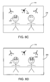
- FIGS. 6A-6D are illustrations of a simplified digital image 205 on display 115 as it undergoes a series of red-eye-correction operations in accordance with yet another illustrative embodiment of the invention.
- FIGS. 7A and 7B are a flowchart of a method for correcting red-eye effect in a digital image in accordance with yet another illustrative embodiment of the invention
- Red-eye correction may be improved by allowing a user to adjust the threshold dynamically.
- the digital image After the digital image has been analyzed to identify candidate red-eye regions, the digital image may be presented to the user, and the candidate red-eye regions whose figures of merit exceed a predetermined initial threshold may be visibly marked within the digital image. As the user adjusts the threshold dynamically, more or fewer candidate red-eye regions may be visibly marked in accordance with the adjusted threshold.
- the predetermined initial threshold may be set less sensitively at the outset to eliminate more false positives (candidate red-eye regions that do not contain a genuine “red eye”). If the algorithm misses genuine “red eyes,” the user may easily compensate by adjusting the threshold to increase the sensitivity. In some cases (i.e., where all false positives have less favorable figures of merit than all of the genuine “red eyes”), the user is not required to reject false positives individually (e.g., by navigating to a visibly marked candidate red-eye region and disqualifying it from subsequent red-eye correction). Instead, the user may eliminate all of the false positives by simply adjusting the threshold in the direction of reduced sensitivity. In cases where at least one false positive has a higher figure of merit than at least one genuine “red eye,” efficient user interface techniques, to be described more fully below, may be employed to reduce the number of actions required of the user to disqualify the false positives.
- FIG. 1A is a functional block diagram of an electronic device 100 in accordance with an illustrative embodiment of the invention.
- Electronic device 100 may be, for example, a desktop computer, a notebook computer, a personal digital assistance (PDA), a digital camera, a radiotelephone (e.g., a cellular or PCS phone), or any other electronic device that is capable of storing and displaying a digital image and performing automatic red-eye correction on the digital image.
- controller 105 communicates over data bus 110 with display 115 , input controls 120 , and memory 125 .
- Controller 105 may comprise, for example, a microprocessor or microcontroller.
- Display 115 may comprise a liquid crystal display (LCD). In some embodiments, display 115 may comprise a touchscreen.
- Input controls 120 may include any input controls, physical or virtual, for controlling the operation of electronic device 100 .
- FIG. 1B is a high-level diagram of memory 125 of electronic device 100 in accordance with an illustrative embodiment of the invention.
- memory 125 may comprise both random access memory (RAM) 130 and non-volatile memory 135 , which may be of the removable variety (e.g., a secure digital or multi-media memory card).
- RAM random access memory
- non-volatile memory 135 which may be of the removable variety (e.g., a secure digital or multi-media memory card).
- Memory 125 may further comprise red-eye analysis logic 140 , red-eye-correction user interface logic 145 , and red-eye correction logic 150 .
- Red-eye analysis logic 140 may identify one or more candidate red-eye regions in a digital image.
- Automatic red-eye correction techniques are well known in the digital image processing art.
- One example may be found in pending U.S. patent application Ser. No. 10/653,019, which is assigned to Hewlett-Packard Company, the disclosure of which is incorporated herein by reference. This reference describes, among other things, a design process in which a large number of features that could potentially help identify “red eyes” are applied to a database of digital images containing “red eyes,” and the features that most effectively distinguish “red eyes” are identified and employed in automatic red-eye correction within an electronic device such as a digital camera or personal computer.
- red-eye analysis logic 140 may assign a figure of merit to each candidate red-eye region.
- the specifics of the figures of merit and the threshold against which they are compared may vary from one implementation to another.
- the figure of merit may vary either directly or inversely with the degree of confidence that the associated candidate red-eye region is a genuine “red eye.” In the former case (direct variation), a “good” candidate red-eye region would have a figure of merit that exceeds the threshold; in the latter case (inverse variation), a “good” candidate red-eye region would have a figure of merit that falls below the threshold.
- Red-eye-correction user interface logic 145 may visibly mark on display 115 the candidate red-eye regions whose confidence scores exceed the threshold. Initially, red-eye-correction user interface logic 145 may do so based on a predetermined initial value of the threshold (e.g., one selected as a reasonable compromise, based on empirical results). As the user adjusts the threshold from its predetermined initial value, red-eye-correction user interface logic 145 may update the visibly marked candidate red-eye regions in accordance with the adjusted threshold. In some embodiments, each discrete adjustment of the threshold (e.g., button press or stylus tap) causes at least one additional or one fewer candidate red-eye region to be visibly marked, depending on the sense in which the threshold is adjusted.
- a predetermined initial value of the threshold e.g., one selected as a reasonable compromise, based on empirical results.
- each discrete adjustment of the threshold e.g., button press or stylus tap
- red-eye-correction user interface logic 145 may quantize the discrete adjustment steps of the threshold such that they coincide with the figures of merit associated with the candidate red-eye regions in a particular digital image.
- red-eye-correction analysis steps such as duplicate removal, a skin tone test, and pair matching after each discrete adjustment of the threshold.
- “Visibly marking” may be implemented in a variety of ways that are well known in the user interface art.
- the candidate red-eye regions whose confidence scores exceed the threshold may be enclosed in a geometric figure (e.g., a bounding box, circle, or other shape).
- a particular color may be chosen for the enclosing geometric figure that helps the visibly marked candidate red-eye regions to stand out from the rest of the digital image.
- Red-eye correction logic 150 may perform red-eye correction in each visibly marked candidate red-eye region after the user has, if necessary, adjusted the threshold or otherwise disqualified (eliminated from red-eye correction) one or more false positives. Though more details are provided in the above-cited reference, red-eye correction essentially involves replacing the red pixels of “red eyes” with those of a more suitable color.
- Red-eye analysis logic 140 , red-eye-correction user interface logic 145 , and red-eye correction logic 150 may be implemented as software, firmware, hardware, or any combination thereof.
- red-eye analysis logic 140 , red-eye-correction user interface logic 145 , and red-eye correction logic 150 may be stored program instructions residing in firmware that are executed by controller 105 .
- the functional boundaries among red-eye analysis logic 140 , red-eye-correction user interface logic 145 , and red-eye correction logic 150 indicated in FIG. 1B are, furthermore, arbitrary. The functionality of these elements may be combined or separated in many other possible ways, and those variations are all considered to be within the scope of the invention as claimed.
- FIG. 1C is an illustration of display 115 and some of the input controls 120 of electronic device 100 in accordance with an illustrative embodiment of the invention.
- electronic device 100 is a digital camera (the back side of which is shown in FIG. 1C ).
- the specifics of display 115 and input controls 120 may differ significantly.
- input controls 120 may include a set of user interface controls 155 comprising two pairs of opposing directional controls, horizontal directional controls 160 and vertical directional controls 165 , and menu/“ok” button 170 .
- This set of user interface controls 155 may comprise physical buttons, as shown in FIG. 1C , or they may comprise virtual buttons on, e.g., a touch-sensitive screen (display 115 ). In the case of a touchscreen, a stylus held by the user may be used to touch particular control elements on display 115 , eliminating the need for most physical buttons.
- the opposing directional controls ( 160 and 165 ) may be used, for example, to navigate among and give focus to items on display 115 . These controls may also be used to toggle the status of particular options in electronic device 100 in a variety of contexts.
- Menu/“ok” button 170 may be used to call up a menu on display 115 or to confirm actions in electronic device 100 (much like an “enter” key on a computer keyboard).
- the set of user interface controls 155 may be, e.g., a mouse, trackball, or other pointing device, and a full-size keyboard may be available to the user.
- a threshold adjustment control allows the user to adjust the threshold in either direction (more or less sensitive).
- a “navigational control” allows the user to navigate to and select (give focus to) a particular candidate red-eye region.
- a “status control” allows the user to disqualify a particular selected candidate red-eye region so that the disqualified candidate red-eye region will not be included in subsequent red-eye correction performed by red-eye correction logic 150 .
- the status control may also be used to requalify a previously disqualified candidate red-eye region (e.g., the user changes his mind after disqualifying a visibly marked candidate red-eye region).
- acceptance input Such an input from the user will sometimes be referred to in this detailed description as an “acceptance input.”
- the threshold adjustment control may be implemented using vertical directional controls 165 . Pressing the “up” arrow, for example, may cause more candidate red-eye regions to be visibly marked, and pressing the “down” arrow may cause fewer candidate red-eye regions to be marked, or vice versa.
- the status control may be implemented using horizontal directional controls 160 . Pressing the “left” arrow, for example, may disqualify a particular selected candidate red-eye region, and pressing the “right” arrow may requalify that candidate red-eye region, undoing the disqualification, or vice versa.
- a navigational control may also be implemented using some or all of the opposing directional controls ( 160 and 165 ).
- all of the foregoing functional controls may also be implemented using a touchscreen and stylus, a mouse, trackball, or other user interface technology.
- the user may touch one or more virtual control elements to adjust the threshold, and a touch of the stylus may be used to navigate to or to disqualify/requalify individual candidate red-eye regions directly.
- a mouse or other pointing device may be used to navigate to or to disqualify/requalify individual candidate red-eye regions directly.
- FIGS. 2A-2C are illustrations of a simplified digital image 205 on display 115 as it undergoes a series of red-eye-correction operations in accordance with an illustrative embodiment of the invention.
- red-eye analysis logic 140 has identified a total of seven candidate red-eye regions 210 , which have been individually identified for convenience in FIG. 2A using letters “A” through “G” in the order of their decreasing confidence (i.e., “A” is the candidate red-eye region 210 whose figure of merit is the most favorable, and “G” is the candidate red-eye region whose figure of merit is the least favorable).
- red-eye-correction user interface logic 145 has visibly marked only those candidate red-eye regions 210 .
- a user has used a threshold adjustment control to include more candidate red-eye regions 210 .
- candidate red-eye region 210 “F” is now visibly marked.
- An additional adjustment of the threshold adjustment control in the same sense would cause “G” to become visibly marked as well.
- a user has used a threshold adjustment control to include fewer candidate red-eye regions 210 .
- a single actuation of the threshold adjustment control in the appropriate sense causes the visible marking of false positive candidate red-eye region 210 “E” to disappear, leaving only valid candidate red-eye regions 210 “A” through “D.”
- the user may issue an input (e.g., pressing menu/“ok” button 170 or touching an appropriate control element with a stylus) to cause red-eye correction logic 150 to perform red-eye correction in each of the visibly marked candidate red-eye regions 210 (“A” through “D”).
- the false positives (“E” through “G”) all have figures of merit that are less favorable than all of the valid candidate red-eye regions 210 (“A” through “D”). Though this is the ideal situation, it may not always occur in practice. In some situations, at least one of the false positives might have a figure of merit that is more favorable than that of at least one of the genuine “red eyes.” In such a case, the user may adjust the threshold to a compromise setting that minimizes the number of false positives but which still corrects all of the valid “red eyes.”
- FIG. 3 is a flowchart of a method for correcting red-eye effect in a digital image in accordance with an illustrative embodiment of the invention.
- FIG. 3 corresponds to the example shown in FIGS. 2A-2C .
- red-eye analysis logic 140 may identify one or more candidate red-eye regions 210 within a digital image 205 .
- Red-eye analysis logic 140 may assign to each candidate red-eye region 210 a confidence score (figure of merit) at 310 .
- red-eye-correction user interface logic 145 may visibly mark the candidate red-eye regions 210 whose confidence scores exceed the initial (nominal) threshold.
- a user may adjust the threshold, and red-eye-correction user interface logic 145 may update the visibly marked candidate red-eye regions 210 in accordance with the adjusted threshold, as explained above.
- the process may proceed to step 330 , where the user is presented with the option to perform red-eye correction on the visibly marked candidate red-eye regions 210 currently shown on display 115 .
- red-eye correction logic 150 may perform red-eye correction on each visibly marked candidate red-eye region 210 .
- the process may terminate.
- FIGS. 4A-4C are illustrations of a simplified digital image 205 on display 115 as it undergoes a series of red-eye-correction operations in accordance with another illustrative embodiment of the invention.
- red-eye analysis logic 140 has identified seven total candidate red-eye regions 210 , six of which (“A” through “F”) have confidence scores exceeding the predetermined initial threshold. Consequently, red-eye-correction user interface logic 145 has visibly marked candidate red-eye regions 210 “A” through “F.”
- successive letters “A” through “G,” in alphabetical order correspond to decreasing confidence scores.
- an arbitrary visibly marked candidate red-eye region 210 is automatically selected by default.
- the selected visibly marked candidate red-eye region 210 happens to be “A,” but it could be any other visibly marked candidate red-eye region 210 (e.g., “F,” which is the lowest-confidence visibly marked candidate red-eye region 210 ).
- a triangular icon (“down” arrow) may be placed below the selected visibly marked candidate red-eye region 210 , as shown in FIG. 4A , to indicate to the user that touching the “down” arrow icon with a stylus or pressing “down” arrow 165 (a rejection input) will disqualify the selected visibly marked candidate red-eye region 210 .
- a status control as defined above, may be provided that allows the user to disqualify or requalify the currently selected visibly marked candidate red-eye region 210 .
- the implementation of the status control suggested by FIG. 4A is merely one example.
- the user has adjusted the threshold to exclude false-positive candidate red-eye region 210 “F.” Note that although the user has succeeded in eliminating one false positive, false-positive candidate red-eye region 210 “D” remains visibly marked. Adjusting the threshold further in the direction of less sensitivity would have the undesired effect of disqualifying valid candidate red-eye region 210 “E.” The user, therefore, needs a means to disqualify false-positive candidate red-eye region 210 “D” without affecting “E.” This can be accomplished by providing the user with a navigational control, as explained above.
- the user may then enter a separate mode, controlled by red-eye-correction user interface logic 145 , in which it is possible to navigate freely among the remaining visibly marked candidate red-eye regions 210 .
- the user has used such a navigational control to navigate to and select visibly marked candidate red-eye region 210 “D.” With “D” selected, the user may use a status control to disqualify “D.”
- additional details of a similar user interface are provided in pending U.S. patent application Ser. No. 10/767,355, which is assigned to Hewlett-Packard Company, the disclosure of which is incorporated herein by reference.
- FIG. 4C shows one example of how red-eye-correction user interface logic 145 may visibly indicate that visibly marked candidate red-eye region 210 “D” has been disqualified.
- visibly marked candidate red-eye region 210 “D” has been crossed through with an “X.”
- the bounding box or other geometric figure enclosing visibly marked candidate red-eye region 210 “D” may be altered in some other way (e.g., it may change color or shape).
- an “up” arrow icon may be placed above visibly marked candidate red-eye region 210 “D” to indicate to the user that touching the “up” arrow icon with a stylus or pressing “up” arrow button 165 (an acceptance input) will requalify visibly marked candidate red-eye region 210 “D.”
- this is merely one possible way of implementing a status control, as defined above, in this context.
- the user may proceed to issue a command to electronic device 100 that invokes red-eye correction logic 150 , which performs red-eye correction in each visibly marked candidate red-eye region that has not been disqualified.
- FIG. 5 is a flowchart of a method for correcting red-eye effect in a digital image in accordance with another illustrative embodiment of the invention.
- FIG. 5 corresponds to the example shown in FIGS. 4A-4C .
- red-eye-correction user interface logic 145 may, at 505 , navigate to and select a particular visibly marked candidate red-eye region 210 in response to the user's actuation of a navigational control.
- red-eye-correction user interface logic 145 may, at 515 , disqualify the particular visibly marked candidate red-eye region 210 .
- red-eye correction logic 150 may, at 525 , perform red-eye correction on each visibly marked candidate red-eye region that has not been disqualified.
- the process may terminate.
- the user may also issue an acceptance input to requalify for subsequent red-eye correction at 525 a visibly marked candidate red-eye region 210 that has been previously disqualified (i.e., whenever a given visibly marked candidate red-eye region 210 is selected, the user may toggle the red-eye correction status of that visibly marked candidate red-eye region 210 using a suitable status control).
- FIGS. 6A-6D illustrate an efficient user interface that combines navigation with disqualification/requalification of visibly marked candidate red-eye regions 210 in accordance with yet another illustrative embodiment of the invention.
- successive letters “A” through “G” correspond, in alphabetical order, to decreasing confidence scores.
- the difficulty again occurs (see FIGS. 4A-4C ) that one of the visibly marked candidate red-eye regions 210 (“C”) has a more favorable figure of merit than two of the valid candidate red-eye regions 210 (“D” and “E”).
- red-eye-correction user interface logic 145 may visibly distinguish the visibly marked candidate red-eye region 210 having the lowest-confidence figure of merit (“lowest-confidence candidate red-eye region” 605 ) from the other visibly marked candidate red-eye regions 210 .
- red-eye-correction user interface logic 145 may also select the lowest-confidence candidate red-eye region 605 for optional disqualification or requalification in response to a rejection or acceptance input, respectively.
- “Visibly distinguished” may mean, for example, that the lowest-confidence candidate red-eye region 605 's enclosing geometric figure blinks or is of a different color than that of the other visibly marked candidate red-eye regions 210 .
- red-eye-correction user interface logic 145 causes the bounding box surrounding the lowest-confidence candidate red-eye region 605 to blink. As the user adjusts the threshold using a threshold adjustment control, red-eye-correction user interface logic 145 updates and visibly distinguishes the lowest-confidence candidate red-eye region 605 accordingly.
- lowest-confidence candidate red-eye region 605 is the visibly marked candidate red-eye region 210 labeled “D.”
- FIGS. 6B-6D show how, using few input commands, the false positives can be disqualified and the four valid “red eyes” (candidate red-eye regions 210 “A,” “B,” “D,” and “E”) can be corrected.
- the user has adjusted the threshold to exclude candidate red-eye region 210 “D.” This action causes the current lowest-confidence candidate red-eye region 605 to become “C” (shown as blinking in FIG. 6B ).
- the user has used a status control to disqualify lowest-confidence candidate red-eye region 605 “C” (crossed through with an “X” in FIG. 6C ).
- the user has adjusted the threshold in the direction of greater sensitivity by two increments to include candidate red-eye regions 210 “D” and “E,” the latter of which has now become lowest-confidence candidate red-eye region 605 .
- the user may proceed to issue a command to electronic device 100 that invokes red-eye correction logic 150 , which performs red-eye correction in each visibly marked candidate red-eye region 210 that has not been disqualified.
- FIGS. 7A and 7B are a flowchart of a method for correcting red-eye effect in a digital image in accordance with yet another illustrative embodiment of the invention.
- FIGS. 7A and 7B correspond to the example shown in FIGS. 6A-6D .
- red-eye-correction user interface logic 145 may, at 705 , visibly distinguish the lowest-confidence candidate red-eye region 605 from the other visibly marked candidate red-eye regions 210 , as explained above.
- red-eye-correction user interface logic 145 may, at 715 , disqualify the lowest-confidence candidate red-eye region 605 from subsequent red-eye correction. If, at 720 , the user is ready to perform red-eye correction, the user may input a suitable command to electronic device 100 to invoke red-eye correction logic 150 , which performs red-eye correction in each visibly marked candidate red-eye region 210 that has not been disqualified. Following red-eye correction at 725 , the process may terminate at 730 . If, however, the user does not initiate red-eye correction at 720 , the process proceeds to step 735 , where the user has the option of making additional threshold adjustments before the process returns to step 705 .
- the user may also issue an acceptance input to requalify for subsequent red-eye correction at 725 a visibly marked candidate red-eye region 210 that has been previously disqualified (i.e., red-eye-correction user interface logic 145 may toggle the red-eye correction status of the lowest-confidence candidate red-eye region 605 in response to a rejection or acceptance input from the user).
Abstract
An electronic device that performs automatic red-eye correction on digital images includes a user-adjustable threshold, enabling the user to adjust the sensitivity of the automatic red-eye-correction algorithm dynamically while viewing marked candidate red-eye locations in a digital image. Such dynamic adjustment of the threshold facilitates the rejection of false positives while reducing the number of input gestures required of the user.
Description
- The present invention relates generally to digital photography and more specifically to user interfaces used in conjunction with the correction of red-eye effect in digital images.
- A pervasive problem in flash photography is the “red-eye effect,” in which an on-camera flash reflects off the back of the eyes of a subject, causing the eyes to appear red. The problem is so common that many digital photo-editing applications include automatic or manual red-eye correction. Some digital cameras are also capable of performing red-eye correction in the camera itself.
- Automatic red-eye correction algorithms typically analyze the digital image based on a number of different features and assign a figure of merit to each potential red-eye region. The figure of merit may represent the degree of confidence that a particular potential red-eye region is indeed a “red eye.” Red-eye correction is then performed on the potential red-eye regions whose figures of merit exceed a predetermined threshold. The predetermined threshold is typically selected to exclude most false positives, but some false positives (e.g., a red button on a person's clothing) may nevertheless end up being corrected erroneously.
- It is thus apparent that there is a need in the art for an improved red-eye correction method and apparatus.
-
FIG. 1A is a functional block diagram of an electronic device in accordance with an illustrative embodiment of the invention. -
FIG. 1B is a high-level diagram of the memory of the electronic device shown inFIG. 1A in accordance with an illustrative embodiment of the invention. -
FIG. 1C is an illustration of the display and input controls of the electronic device shown inFIG. 1A in accordance with an illustrative embodiment of the invention. -
FIGS. 2A-2C are illustrations of a simplifieddigital image 205 ondisplay 115 as it undergoes a series of red-eye-correction operations in accordance with an illustrative embodiment of the invention. -
FIG. 3 is a flowchart of a method for correcting red-eye effect in a digital image in accordance with an illustrative embodiment of the invention. -
FIGS. 4A-4C are illustrations of a simplifieddigital image 205 ondisplay 115 as it undergoes a series of red-eye-correction operations in accordance with another illustrative embodiment of the invention. -
FIG. 5 is a flowchart of a method for correcting red-eye effect in a digital image in accordance with another illustrative embodiment of the invention. -
FIGS. 6A-6D are illustrations of a simplifieddigital image 205 ondisplay 115 as it undergoes a series of red-eye-correction operations in accordance with yet another illustrative embodiment of the invention. -
FIGS. 7A and 7B are a flowchart of a method for correcting red-eye effect in a digital image in accordance with yet another illustrative embodiment of the invention - Red-eye correction may be improved by allowing a user to adjust the threshold dynamically. After the digital image has been analyzed to identify candidate red-eye regions, the digital image may be presented to the user, and the candidate red-eye regions whose figures of merit exceed a predetermined initial threshold may be visibly marked within the digital image. As the user adjusts the threshold dynamically, more or fewer candidate red-eye regions may be visibly marked in accordance with the adjusted threshold.
- One advantage of this approach is that the predetermined initial threshold may be set less sensitively at the outset to eliminate more false positives (candidate red-eye regions that do not contain a genuine “red eye”). If the algorithm misses genuine “red eyes,” the user may easily compensate by adjusting the threshold to increase the sensitivity. In some cases (i.e., where all false positives have less favorable figures of merit than all of the genuine “red eyes”), the user is not required to reject false positives individually (e.g., by navigating to a visibly marked candidate red-eye region and disqualifying it from subsequent red-eye correction). Instead, the user may eliminate all of the false positives by simply adjusting the threshold in the direction of reduced sensitivity. In cases where at least one false positive has a higher figure of merit than at least one genuine “red eye,” efficient user interface techniques, to be described more fully below, may be employed to reduce the number of actions required of the user to disqualify the false positives.
-
FIG. 1A is a functional block diagram of anelectronic device 100 in accordance with an illustrative embodiment of the invention.Electronic device 100 may be, for example, a desktop computer, a notebook computer, a personal digital assistance (PDA), a digital camera, a radiotelephone (e.g., a cellular or PCS phone), or any other electronic device that is capable of storing and displaying a digital image and performing automatic red-eye correction on the digital image. InFIG. 1A ,controller 105 communicates overdata bus 110 withdisplay 115,input controls 120, andmemory 125.Controller 105 may comprise, for example, a microprocessor or microcontroller.Display 115 may comprise a liquid crystal display (LCD). In some embodiments,display 115 may comprise a touchscreen.Input controls 120 may include any input controls, physical or virtual, for controlling the operation ofelectronic device 100. -
FIG. 1B is a high-level diagram ofmemory 125 ofelectronic device 100 in accordance with an illustrative embodiment of the invention. In general,memory 125 may comprise both random access memory (RAM) 130 andnon-volatile memory 135, which may be of the removable variety (e.g., a secure digital or multi-media memory card).Memory 125 may further comprise red-eye analysis logic 140, red-eye-correctionuser interface logic 145, and red-eye correction logic 150. - Red-
eye analysis logic 140 may identify one or more candidate red-eye regions in a digital image. Automatic red-eye correction techniques are well known in the digital image processing art. One example may be found in pending U.S. patent application Ser. No. 10/653,019, which is assigned to Hewlett-Packard Company, the disclosure of which is incorporated herein by reference. This reference describes, among other things, a design process in which a large number of features that could potentially help identify “red eyes” are applied to a database of digital images containing “red eyes,” and the features that most effectively distinguish “red eyes” are identified and employed in automatic red-eye correction within an electronic device such as a digital camera or personal computer. - Using techniques such as those discussed in the cited reference, red-
eye analysis logic 140 may assign a figure of merit to each candidate red-eye region. The specifics of the figures of merit and the threshold against which they are compared may vary from one implementation to another. For example, depending on the implementation, the figure of merit may vary either directly or inversely with the degree of confidence that the associated candidate red-eye region is a genuine “red eye.” In the former case (direct variation), a “good” candidate red-eye region would have a figure of merit that exceeds the threshold; in the latter case (inverse variation), a “good” candidate red-eye region would have a figure of merit that falls below the threshold. To avoid confusion on this point, it will be assumed throughout this detailed description and in the claims that follow, without loss of generality, that a candidate red-eye region whose associated figure of merit “exceeds a threshold” qualifies for visible marking and presentation to the user ondisplay 115, regardless of whether the figure of merit varies directly or inversely (or in some other fashion) with the degree of confidence. In this detailed description, “confidence score” will sometimes be used interchangeably with “figure of merit.” - Red-eye-correction
user interface logic 145 may visibly mark ondisplay 115 the candidate red-eye regions whose confidence scores exceed the threshold. Initially, red-eye-correctionuser interface logic 145 may do so based on a predetermined initial value of the threshold (e.g., one selected as a reasonable compromise, based on empirical results). As the user adjusts the threshold from its predetermined initial value, red-eye-correctionuser interface logic 145 may update the visibly marked candidate red-eye regions in accordance with the adjusted threshold. In some embodiments, each discrete adjustment of the threshold (e.g., button press or stylus tap) causes at least one additional or one fewer candidate red-eye region to be visibly marked, depending on the sense in which the threshold is adjusted. That is, red-eye-correctionuser interface logic 145 may quantize the discrete adjustment steps of the threshold such that they coincide with the figures of merit associated with the candidate red-eye regions in a particular digital image. Those skilled in the art will recognize that it may be advantageous to repeat certain red-eye-correction analysis steps such as duplicate removal, a skin tone test, and pair matching after each discrete adjustment of the threshold. - “Visibly marking” may be implemented in a variety of ways that are well known in the user interface art. For example, the candidate red-eye regions whose confidence scores exceed the threshold may be enclosed in a geometric figure (e.g., a bounding box, circle, or other shape). A particular color may be chosen for the enclosing geometric figure that helps the visibly marked candidate red-eye regions to stand out from the rest of the digital image.
- Red-
eye correction logic 150 may perform red-eye correction in each visibly marked candidate red-eye region after the user has, if necessary, adjusted the threshold or otherwise disqualified (eliminated from red-eye correction) one or more false positives. Though more details are provided in the above-cited reference, red-eye correction essentially involves replacing the red pixels of “red eyes” with those of a more suitable color. - Red-
eye analysis logic 140, red-eye-correctionuser interface logic 145, and red-eye correction logic 150 may be implemented as software, firmware, hardware, or any combination thereof. In one embodiment, red-eye analysis logic 140, red-eye-correctionuser interface logic 145, and red-eye correction logic 150 may be stored program instructions residing in firmware that are executed bycontroller 105. The functional boundaries among red-eye analysis logic 140, red-eye-correctionuser interface logic 145, and red-eye correction logic 150 indicated inFIG. 1B are, furthermore, arbitrary. The functionality of these elements may be combined or separated in many other possible ways, and those variations are all considered to be within the scope of the invention as claimed. -
FIG. 1C is an illustration ofdisplay 115 and some of the input controls 120 ofelectronic device 100 in accordance with an illustrative embodiment of the invention. InFIG. 1C , it has been assumed for illustrative purposes thatelectronic device 100 is a digital camera (the back side of which is shown inFIG. 1C ). In other embodiments in whichelectronic device 100 is of a different type or in which a different kind of user interface is employed, the specifics ofdisplay 115 and input controls 120 may differ significantly. InFIG. 1C , input controls 120 may include a set of user interface controls 155 comprising two pairs of opposing directional controls, horizontaldirectional controls 160 and verticaldirectional controls 165, and menu/“ok”button 170. This set of user interface controls 155 may comprise physical buttons, as shown inFIG. 1C , or they may comprise virtual buttons on, e.g., a touch-sensitive screen (display 115). In the case of a touchscreen, a stylus held by the user may be used to touch particular control elements ondisplay 115, eliminating the need for most physical buttons. The opposing directional controls (160 and 165) may be used, for example, to navigate among and give focus to items ondisplay 115. These controls may also be used to toggle the status of particular options inelectronic device 100 in a variety of contexts. Menu/“ok”button 170 may be used to call up a menu ondisplay 115 or to confirm actions in electronic device 100 (much like an “enter” key on a computer keyboard). In embodiments in whichelectronic device 100 is a computing device such as a desktop or notebook computer, the set of user interface controls 155 may be, e.g., a mouse, trackball, or other pointing device, and a full-size keyboard may be available to the user. - Of the various input controls 120, three types of functional input controls are of particular utility in the context of the invention: (1) a threshold adjustment control, (2) a navigational control, and (3) a status control. A “threshold adjustment control” allows the user to adjust the threshold in either direction (more or less sensitive). A “navigational control” allows the user to navigate to and select (give focus to) a particular candidate red-eye region. A “status control” allows the user to disqualify a particular selected candidate red-eye region so that the disqualified candidate red-eye region will not be included in subsequent red-eye correction performed by red-
eye correction logic 150. Such an input from the user will sometimes be referred to in this detailed description as a “rejection input.” In some embodiments, the status control may also be used to requalify a previously disqualified candidate red-eye region (e.g., the user changes his mind after disqualifying a visibly marked candidate red-eye region). Such an input from the user will sometimes be referred to in this detailed description as an “acceptance input.” - All three of the foregoing functional input controls may be implemented using any suitable user interface technology, including the illustrative examples mentioned above. For example, in one embodiment, the threshold adjustment control may be implemented using vertical
directional controls 165. Pressing the “up” arrow, for example, may cause more candidate red-eye regions to be visibly marked, and pressing the “down” arrow may cause fewer candidate red-eye regions to be marked, or vice versa. To cite a further example, the status control may be implemented using horizontaldirectional controls 160. Pressing the “left” arrow, for example, may disqualify a particular selected candidate red-eye region, and pressing the “right” arrow may requalify that candidate red-eye region, undoing the disqualification, or vice versa. A navigational control may also be implemented using some or all of the opposing directional controls (160 and 165). However, all of the foregoing functional controls may also be implemented using a touchscreen and stylus, a mouse, trackball, or other user interface technology. In the case of a touchscreen, for example, the user may touch one or more virtual control elements to adjust the threshold, and a touch of the stylus may be used to navigate to or to disqualify/requalify individual candidate red-eye regions directly. The same is true of a mouse or other pointing device. - Three particular illustrative embodiments of the invention will now be described in succession using a series of illustrations and a method flowchart for each embodiment.
-
FIGS. 2A-2C are illustrations of a simplifieddigital image 205 ondisplay 115 as it undergoes a series of red-eye-correction operations in accordance with an illustrative embodiment of the invention. InFIG. 2A , red-eye analysis logic 140 has identified a total of seven candidate red-eye regions 210, which have been individually identified for convenience inFIG. 2A using letters “A” through “G” in the order of their decreasing confidence (i.e., “A” is the candidate red-eye region 210 whose figure of merit is the most favorable, and “G” is the candidate red-eye region whose figure of merit is the least favorable). (To avoid cluttering the figure, only one candidate red-eye region 210 (“A”) has been annotated with a reference numeral.) InFIG. 2A , candidate red-eye regions 210 “A” through “E” have figures of merit that exceed the predetermined initial value of the threshold. Therefore, red-eye-correctionuser interface logic 145 has visibly marked only those candidate red-eye regions 210. - In
FIG. 2B , a user has used a threshold adjustment control to include more candidate red-eye regions 210. Note that candidate red-eye region 210 “F” is now visibly marked. An additional adjustment of the threshold adjustment control in the same sense would cause “G” to become visibly marked as well. - In
FIG. 2C , a user has used a threshold adjustment control to include fewer candidate red-eye regions 210. Relative toFIG. 2A , a single actuation of the threshold adjustment control in the appropriate sense causes the visible marking of false positive candidate red-eye region 210 “E” to disappear, leaving only valid candidate red-eye regions 210 “A” through “D.” At this point, the user may issue an input (e.g., pressing menu/“ok”button 170 or touching an appropriate control element with a stylus) to cause red-eye correction logic 150 to perform red-eye correction in each of the visibly marked candidate red-eye regions 210 (“A” through “D”). - In the example of
FIGS. 2A-2C , the false positives (“E” through “G”) all have figures of merit that are less favorable than all of the valid candidate red-eye regions 210 (“A” through “D”). Though this is the ideal situation, it may not always occur in practice. In some situations, at least one of the false positives might have a figure of merit that is more favorable than that of at least one of the genuine “red eyes.” In such a case, the user may adjust the threshold to a compromise setting that minimizes the number of false positives but which still corrects all of the valid “red eyes.” -
FIG. 3 is a flowchart of a method for correcting red-eye effect in a digital image in accordance with an illustrative embodiment of the invention.FIG. 3 corresponds to the example shown inFIGS. 2A-2C . At 305, red-eye analysis logic 140 may identify one or more candidate red-eye regions 210 within adigital image 205. Red-eye analysis logic 140 may assign to each candidate red-eye region 210 a confidence score (figure of merit) at 310. At 315, red-eye-correctionuser interface logic 145 may visibly mark the candidate red-eye regions 210 whose confidence scores exceed the initial (nominal) threshold. Atsteps user interface logic 145 may update the visibly marked candidate red-eye regions 210 in accordance with the adjusted threshold, as explained above. Once the user has finished adjusting the threshold, the process may proceed to step 330, where the user is presented with the option to perform red-eye correction on the visibly marked candidate red-eye regions 210 currently shown ondisplay 115. At 335, red-eye correction logic 150 may perform red-eye correction on each visibly marked candidate red-eye region 210. At 340, the process may terminate. -
FIGS. 4A-4C are illustrations of a simplifieddigital image 205 ondisplay 115 as it undergoes a series of red-eye-correction operations in accordance with another illustrative embodiment of the invention. InFIG. 4A , red-eye analysis logic 140 has identified seven total candidate red-eye regions 210, six of which (“A” through “F”) have confidence scores exceeding the predetermined initial threshold. Consequently, red-eye-correctionuser interface logic 145 has visibly marked candidate red-eye regions 210 “A” through “F.” As inFIGS. 2A-2C , successive letters “A” through “G,” in alphabetical order, correspond to decreasing confidence scores. In this particular embodiment, an arbitrary visibly marked candidate red-eye region 210 is automatically selected by default. In this illustrative example, the selected visibly marked candidate red-eye region 210 happens to be “A,” but it could be any other visibly marked candidate red-eye region 210 (e.g., “F,” which is the lowest-confidence visibly marked candidate red-eye region 210). Optionally, a triangular icon (“down” arrow) may be placed below the selected visibly marked candidate red-eye region 210, as shown inFIG. 4A , to indicate to the user that touching the “down” arrow icon with a stylus or pressing “down” arrow 165 (a rejection input) will disqualify the selected visibly marked candidate red-eye region 210. In general, a status control, as defined above, may be provided that allows the user to disqualify or requalify the currently selected visibly marked candidate red-eye region 210. The implementation of the status control suggested byFIG. 4A is merely one example. - In
FIG. 4B , the user has adjusted the threshold to exclude false-positive candidate red-eye region 210 “F.” Note that although the user has succeeded in eliminating one false positive, false-positive candidate red-eye region 210 “D” remains visibly marked. Adjusting the threshold further in the direction of less sensitivity would have the undesired effect of disqualifying valid candidate red-eye region 210 “E.” The user, therefore, needs a means to disqualify false-positive candidate red-eye region 210 “D” without affecting “E.” This can be accomplished by providing the user with a navigational control, as explained above. Once the user has adjusted the threshold to the desired level, the user may then enter a separate mode, controlled by red-eye-correctionuser interface logic 145, in which it is possible to navigate freely among the remaining visibly marked candidate red-eye regions 210. InFIG. 4B , the user has used such a navigational control to navigate to and select visibly marked candidate red-eye region 210 “D.” With “D” selected, the user may use a status control to disqualify “D.” Regarding navigation among individual visibly marked candidate red-eye regions 210, additional details of a similar user interface are provided in pending U.S. patent application Ser. No. 10/767,355, which is assigned to Hewlett-Packard Company, the disclosure of which is incorporated herein by reference. - In
FIG. 4C , the user has disqualified visibly marked candidate red-eye region 210 “D.”FIG. 4C shows one example of how red-eye-correctionuser interface logic 145 may visibly indicate that visibly marked candidate red-eye region 210 “D” has been disqualified. InFIG. 4C , visibly marked candidate red-eye region 210 “D” has been crossed through with an “X.” In other embodiments, the bounding box or other geometric figure enclosing visibly marked candidate red-eye region 210 “D” may be altered in some other way (e.g., it may change color or shape). Optionally, an “up” arrow icon may be placed above visibly marked candidate red-eye region 210 “D” to indicate to the user that touching the “up” arrow icon with a stylus or pressing “up” arrow button 165 (an acceptance input) will requalify visibly marked candidate red-eye region 210 “D.” Again, this is merely one possible way of implementing a status control, as defined above, in this context. With all the valid candidate red-eye regions 210 (“A” through “E”) visibly marked and false-positive visibly marked candidate red-eye region 210 “D” disqualified as shown inFIG. 4C , the user may proceed to issue a command toelectronic device 100 that invokes red-eye correction logic 150, which performs red-eye correction in each visibly marked candidate red-eye region that has not been disqualified. -
FIG. 5 is a flowchart of a method for correcting red-eye effect in a digital image in accordance with another illustrative embodiment of the invention.FIG. 5 corresponds to the example shown inFIGS. 4A-4C . Aftersteps FIG. 3 (those involving adjustment of the threshold) have been performed, red-eye-correctionuser interface logic 145 may, at 505, navigate to and select a particular visibly marked candidate red-eye region 210 in response to the user's actuation of a navigational control. If a rejection input is received from the user at 510, red-eye-correctionuser interface logic 145 may, at 515, disqualify the particular visibly marked candidate red-eye region 210. Once the user has finished navigating to and disqualifying false positives at 520, red-eye correction logic 150 may, at 525, perform red-eye correction on each visibly marked candidate red-eye region that has not been disqualified. At 530, the process may terminate. - Though not shown in
FIG. 5 to promote clarity, at a step analogous to step 510, the user may also issue an acceptance input to requalify for subsequent red-eye correction at 525 a visibly marked candidate red-eye region 210 that has been previously disqualified (i.e., whenever a given visibly marked candidate red-eye region 210 is selected, the user may toggle the red-eye correction status of that visibly marked candidate red-eye region 210 using a suitable status control). -
FIGS. 6A-6D illustrate an efficient user interface that combines navigation with disqualification/requalification of visibly marked candidate red-eye regions 210 in accordance with yet another illustrative embodiment of the invention. As inFIGS. 2A-2C , successive letters “A” through “G” correspond, in alphabetical order, to decreasing confidence scores. InFIG. 6A , the difficulty again occurs (seeFIGS. 4A-4C ) that one of the visibly marked candidate red-eye regions 210 (“C”) has a more favorable figure of merit than two of the valid candidate red-eye regions 210 (“D” and “E”). In this particular embodiment, red-eye-correctionuser interface logic 145 may visibly distinguish the visibly marked candidate red-eye region 210 having the lowest-confidence figure of merit (“lowest-confidence candidate red-eye region” 605) from the other visibly marked candidate red-eye regions 210. At the same time, red-eye-correctionuser interface logic 145 may also select the lowest-confidence candidate red-eye region 605 for optional disqualification or requalification in response to a rejection or acceptance input, respectively. “Visibly distinguished” may mean, for example, that the lowest-confidence candidate red-eye region 605's enclosing geometric figure blinks or is of a different color than that of the other visibly marked candidate red-eye regions 210. In general, any technique that visibly differentiates lowest-confidence candidate red-eye region 605 from all other visibly marked candidate red-eye regions 210 may be employed. In the example ofFIGS. 6A-6D , red-eye-correctionuser interface logic 145 causes the bounding box surrounding the lowest-confidence candidate red-eye region 605 to blink. As the user adjusts the threshold using a threshold adjustment control, red-eye-correctionuser interface logic 145 updates and visibly distinguishes the lowest-confidence candidate red-eye region 605 accordingly. InFIG. 6A , lowest-confidence candidate red-eye region 605 is the visibly marked candidate red-eye region 210 labeled “D.”FIGS. 6B-6D show how, using few input commands, the false positives can be disqualified and the four valid “red eyes” (candidate red-eye regions 210 “A,” “B,” “D,” and “E”) can be corrected. - In
FIG. 6B , the user has adjusted the threshold to exclude candidate red-eye region 210 “D.” This action causes the current lowest-confidence candidate red-eye region 605 to become “C” (shown as blinking inFIG. 6B ). - In
FIG. 6C , the user has used a status control to disqualify lowest-confidence candidate red-eye region 605 “C” (crossed through with an “X” inFIG. 6C ). - In
FIG. 6D , the user has adjusted the threshold in the direction of greater sensitivity by two increments to include candidate red-eye regions 210 “D” and “E,” the latter of which has now become lowest-confidence candidate red-eye region 605. At this point, the user may proceed to issue a command toelectronic device 100 that invokes red-eye correction logic 150, which performs red-eye correction in each visibly marked candidate red-eye region 210 that has not been disqualified. -
FIGS. 7A and 7B are a flowchart of a method for correcting red-eye effect in a digital image in accordance with yet another illustrative embodiment of the invention.FIGS. 7A and 7B correspond to the example shown inFIGS. 6A-6D . Aftersteps FIG. 3 have been performed, red-eye-correctionuser interface logic 145 may, at 705, visibly distinguish the lowest-confidence candidate red-eye region 605 from the other visibly marked candidate red-eye regions 210, as explained above. If a rejection input is received from the user at 710, red-eye-correctionuser interface logic 145 may, at 715, disqualify the lowest-confidence candidate red-eye region 605 from subsequent red-eye correction. If, at 720, the user is ready to perform red-eye correction, the user may input a suitable command toelectronic device 100 to invoke red-eye correction logic 150, which performs red-eye correction in each visibly marked candidate red-eye region 210 that has not been disqualified. Following red-eye correction at 725, the process may terminate at 730. If, however, the user does not initiate red-eye correction at 720, the process proceeds to step 735, where the user has the option of making additional threshold adjustments before the process returns to step 705. - Though not shown in
FIG. 7A to promote clarity, at a step analogous to step 710, the user may also issue an acceptance input to requalify for subsequent red-eye correction at 725 a visibly marked candidate red-eye region 210 that has been previously disqualified (i.e., red-eye-correctionuser interface logic 145 may toggle the red-eye correction status of the lowest-confidence candidate red-eye region 605 in response to a rejection or acceptance input from the user). - The foregoing description of the present invention has been presented for the purposes of illustration and description. It is not intended to be exhaustive or to limit the invention to the precise form disclosed, and other modifications and variations may be possible in light of the above teachings. The embodiments were chosen and described in order to best explain the principles of the invention and its practical application to thereby enable others skilled in the art to best utilize the invention in various embodiments and various modifications as are suited to the particular use contemplated. It is intended that the appended claims be construed to include other alternative embodiments of the invention except insofar as limited by the prior art.
Claims (30)
1. A method for correcting red-eye effect in a digital image, comprising:
identifying automatically at least one candidate red-eye region within the digital image;
assigning a confidence score to each candidate red-eye region;
visibly marking for a user the candidate red-eye regions whose confidence scores exceed a threshold, the threshold having a predetermined initial value; and
adjusting the threshold dynamically in response to input from the user.
2. The method of claim 1 , further comprising:
updating which candidate red-eye regions are visibly marked in accordance with the threshold as the threshold is dynamically adjusted.
3. The method of claim 2 , wherein at least one additional candidate red-eye region is visibly marked, when the threshold is adjusted in a first sense, and at least one fewer candidate red-eye region is visibly marked, when the threshold is adjusted in a second sense opposite the first sense.
4. The method of claim 2 , further comprising:
producing a modified digital image by performing red-eye correction in each visibly marked candidate red-eye region.
5. The method of claim 2 , further comprising:
selecting and distinguishing visibly from the other visibly marked candidate red-eye regions a lowest-confidence candidate red-eye region, the lowest-confidence candidate red-eye region having a least favorable confidence score among the visibly marked candidate red-eye regions; and
disqualifying the lowest-confidence candidate red-eye region as a candidate red-eye region in response to a rejection input from the user.
6. The method of claim 5 , further comprising:
visibly indicating that the lowest-confidence candidate red-eye region has been disqualified as a candidate red-eye region.
7. The method of claim 5 , further comprising:
requalifying the lowest-confidence candidate red-eye region as a candidate red-eye region in response to an acceptance input from the user.
8. The method of claim 5 , further comprising:
producing a modified digital image by performing red-eye correction in each visibly marked candidate red-eye region that has not been disqualified.
9. The method of claim 2 , further comprising:
navigating to and selecting a particular visibly marked candidate red-eye region in response to a navigation input from the user; and
disqualifying the particular candidate red-eye region as a candidate red-eye region in response to a rejection input from the user.
10. The method of claim 9 , further comprising:
producing a modified digital image by performing red-eye correction in each visibly marked candidate red-eye region that has not been disqualified.
11. The method of claim 1 , wherein visibly marking for a user the candidate red-eye regions whose confidence scores exceed a threshold comprises enclosing each of those candidate red-eye regions within a geometric figure.
12. A method for correcting red-eye effect in a digital image, comprising:
identifying automatically at least one candidate red-eye region within the digital image;
assigning a figure of merit to each candidate red-eye region;
visibly marking for a user the candidate red-eye regions whose figures of merit exceed a threshold, the threshold having a predetermined initial value;
adjusting the threshold dynamically in response to input from the user; and
updating which candidate red-eye regions are visibly marked in accordance with the threshold as the threshold is dynamically adjusted.
13. The method of claim 12 , further comprising:
performing red-eye correction in each of the visibly marked candidate red-eye regions.
14. The method of claim 12 , further comprising:
selecting and distinguishing visibly from the other visibly marked candidate red-eye regions a lowest-confidence candidate red-eye region, the lowest-confidence candidate red-eye region having a least favorable figure of merit among the visibly marked candidate red-eye regions; and
disqualifying the lowest-confidence candidate red-eye region as a candidate red-eye region in response to a rejection input from the user.
15. The method of claim 14 , further comprising:
requalifying the lowest-confidence candidate red-eye region as a candidate red-eye region in response to an acceptance input from the user.
16. The method of claim 14 , further comprising:
performing red-eye correction in each visibly marked candidate red-eye region that has not been disqualified.
17. An electronic device, comprising:
a memory in which to store a digital image;
a display on which to show the digital image;
red-eye analysis logic to identify automatically at least one candidate red-eye region within the digital image, the red-eye analysis logic being configured to assign a figure of merit to each candidate red-eye region;
red-eye-correction user interface logic configured to mark visibly for a user on the display the candidate red-eye regions whose figures of merit exceed a threshold, the threshold having a predetermined initial value; and
a threshold adjustment control with which the user may adjust the threshold.
18. The electronic device of claim 17 , wherein the threshold adjustment control comprises a pair of opposing directional controls.
19. The electronic device of claim 17 , wherein the red-eye-correction user interface logic is configured to update which candidate red-eye regions are visibly marked in accordance with the threshold as the threshold is adjusted.
20. The electronic device of claim 19 , wherein the red-eye-correction user interface logic is configured to mark visibly at least one additional candidate red-eye region, when the threshold adjustment control is actuated in a first sense, and to mark visibly at least one fewer candidate red-eye region, when the threshold adjustment control is actuated in a second sense opposite the first sense.
21. The electronic device of claim 19 , further comprising:
red-eye correction logic to perform red-eye correction in each visibly marked candidate red-eye region.
22. The electronic device of claim 19 , further comprising:
a status control with which the user may indicate either one of rejection and acceptance; and
wherein the red-eye-correction user interface logic is further configured to
select and distinguish visibly from the other visibly marked candidate red-eye regions a lowest-confidence candidate red-eye region, the lowest-confidence candidate red-eye region having a least favorable figure of merit among the visibly marked candidate red-eye regions;
disqualify the lowest-confidence candidate red-eye region as a candidate red-eye region, when the user indicates rejection using the status control; and
requalify the lowest-confidence candidate red-eye region as a candidate red-eye region when, subsequent to disqualification of the lowest-confidence candidate red-eye region, the user indicates acceptance using the status control.
23. The electronic device of claim 22 , wherein the status control comprises a pair of opposing directional controls.
24. The electronic device of claim 22 , wherein the red-eye-correction user interface logic is further configured to indicate visibly that the lowest-confidence candidate red-eye region has been disqualified as a candidate red-eye region.
25. The electronic device of claim 22 , further comprising:
red-eye correction logic to perform red-eye correction in each visibly marked candidate red-eye region that has not been disqualified.
26. The electronic device of claim 19 , further comprising:
a navigational control to navigate to and select a particular visibly marked candidate red-eye region;
a status control with which the user may indicate either one of rejection and acceptance; and
wherein the red-eye-correction user interface logic is further configured to
disqualify the particular visibly marked candidate red-eye region as a candidate red-eye region, when the user indicates rejection using the status control; and
requalify the particular visibly marked candidate red-eye region as a candidate red-eye region, when the user indicates acceptance using the status control subsequent to disqualification of the particular visibly marked candidate red-eye region.
27. The electronic device of claim 26 , wherein the navigational control comprises a pair of opposing directional controls.
28. The electronic device of claim 26 , further comprising:
red-eye correction logic to perform red-eye correction in each visibly marked candidate red-eye region that has not been disqualified.
29. The electronic device of claim 17 , wherein the electronic device is one of a desktop computer, a notebook computer, a PDA, a digital camera, and a radiotelephone.
30. An electronic device, comprising:
means for storing a digital image;
means for displaying the digital image;
means for identifying automatically at least one candidate red-eye region in the digital image, the means for identifying automatically at least one candidate red-eye region in the digital image being configured to assign a confidence score to each candidate red-eye region;
means for marking visibly for a user the candidate red-eye regions whose confidence scores exceed a threshold, the threshold having a predetermined initial value; and
means for adjusting the threshold in response to input from a user.
Priority Applications (2)
| Application Number | Priority Date | Filing Date | Title |
|---|---|---|---|
| US11/148,680 US20060280375A1 (en) | 2005-06-08 | 2005-06-08 | Red-eye correction method and apparatus with user-adjustable threshold |
| JP2006159507A JP4275151B2 (en) | 2005-06-08 | 2006-06-08 | Red-eye correction method and apparatus using user-adjustable threshold |
Applications Claiming Priority (1)
| Application Number | Priority Date | Filing Date | Title |
|---|---|---|---|
| US11/148,680 US20060280375A1 (en) | 2005-06-08 | 2005-06-08 | Red-eye correction method and apparatus with user-adjustable threshold |
Publications (1)
| Publication Number | Publication Date |
|---|---|
| US20060280375A1 true US20060280375A1 (en) | 2006-12-14 |
Family
ID=37524154
Family Applications (1)
| Application Number | Title | Priority Date | Filing Date |
|---|---|---|---|
| US11/148,680 Abandoned US20060280375A1 (en) | 2005-06-08 | 2005-06-08 | Red-eye correction method and apparatus with user-adjustable threshold |
Country Status (2)
| Country | Link |
|---|---|
| US (1) | US20060280375A1 (en) |
| JP (1) | JP4275151B2 (en) |
Cited By (18)
| Publication number | Priority date | Publication date | Assignee | Title |
|---|---|---|---|---|
| US20070269108A1 (en) * | 2006-05-03 | 2007-11-22 | Fotonation Vision Limited | Foreground / Background Separation in Digital Images |
| US20080317376A1 (en) * | 2007-06-20 | 2008-12-25 | Microsoft Corporation | Automatic image correction providing multiple user-selectable options |
| US20090080797A1 (en) * | 2007-09-25 | 2009-03-26 | Fotonation Vision, Ltd. | Eye Defect Detection in International Standards Organization Images |
| US20100328442A1 (en) * | 2009-06-25 | 2010-12-30 | Pixart Imaging Inc. | Human face detection and tracking device |
| US20110074985A1 (en) * | 2005-11-18 | 2011-03-31 | Tessera Technologies Ireland Limited | Method and Apparatus of Correcting Hybrid Flash Artifacts in Digital Images |
| US20110080499A1 (en) * | 1997-10-09 | 2011-04-07 | Tessera Technologies Ireland Limited | Red-eye filter method and apparatus |
| US7995804B2 (en) * | 2007-03-05 | 2011-08-09 | Tessera Technologies Ireland Limited | Red eye false positive filtering using face location and orientation |
| US20110228135A1 (en) * | 2005-11-18 | 2011-09-22 | Tessera Technologies Ireland Limited | Two Stage Detection For Photographic Eye Artifacts |
| US8126217B2 (en) | 2005-11-18 | 2012-02-28 | DigitalOptics Corporation Europe Limited | Two stage detection for photographic eye artifacts |
| US8160308B2 (en) | 2005-11-18 | 2012-04-17 | DigitalOptics Corporation Europe Limited | Two stage detection for photographic eye artifacts |
| US8170294B2 (en) | 2006-11-10 | 2012-05-01 | DigitalOptics Corporation Europe Limited | Method of detecting redeye in a digital image |
| US8212864B2 (en) | 2008-01-30 | 2012-07-03 | DigitalOptics Corporation Europe Limited | Methods and apparatuses for using image acquisition data to detect and correct image defects |
| US8264575B1 (en) | 1997-10-09 | 2012-09-11 | DigitalOptics Corporation Europe Limited | Red eye filter method and apparatus |
| US20120275650A1 (en) * | 2006-12-22 | 2012-11-01 | Canon Kabushiki Kaisha | Method and apparatus for detecting and processing specific pattern from image |
| US8320641B2 (en) | 2004-10-28 | 2012-11-27 | DigitalOptics Corporation Europe Limited | Method and apparatus for red-eye detection using preview or other reference images |
| US8537251B2 (en) | 1997-10-09 | 2013-09-17 | DigitalOptics Corporation Europe Limited | Detecting red eye filter and apparatus using meta-data |
| US8970125B2 (en) | 2009-12-02 | 2015-03-03 | Panasonic Industrial Devices Sunx Co., Ltd. | UV irradiation apparatus |
| CN108124268A (en) * | 2016-11-30 | 2018-06-05 | 中国移动通信有限公司研究院 | A kind of parameter accuracy recognition methods and the network equipment |
Citations (2)
| Publication number | Priority date | Publication date | Assignee | Title |
|---|---|---|---|---|
| US20040041924A1 (en) * | 2002-08-29 | 2004-03-04 | White Timothy J. | Apparatus and method for processing digital images having eye color defects |
| US20040114829A1 (en) * | 2002-10-10 | 2004-06-17 | Intelligent System Solutions Corp. | Method and system for detecting and correcting defects in a digital image |
-
2005
- 2005-06-08 US US11/148,680 patent/US20060280375A1/en not_active Abandoned
-
2006
- 2006-06-08 JP JP2006159507A patent/JP4275151B2/en not_active Expired - Fee Related
Patent Citations (2)
| Publication number | Priority date | Publication date | Assignee | Title |
|---|---|---|---|---|
| US20040041924A1 (en) * | 2002-08-29 | 2004-03-04 | White Timothy J. | Apparatus and method for processing digital images having eye color defects |
| US20040114829A1 (en) * | 2002-10-10 | 2004-06-17 | Intelligent System Solutions Corp. | Method and system for detecting and correcting defects in a digital image |
Cited By (35)
| Publication number | Priority date | Publication date | Assignee | Title |
|---|---|---|---|---|
| US20110080499A1 (en) * | 1997-10-09 | 2011-04-07 | Tessera Technologies Ireland Limited | Red-eye filter method and apparatus |
| US8203621B2 (en) | 1997-10-09 | 2012-06-19 | DigitalOptics Corporation Europe Limited | Red-eye filter method and apparatus |
| US8537251B2 (en) | 1997-10-09 | 2013-09-17 | DigitalOptics Corporation Europe Limited | Detecting red eye filter and apparatus using meta-data |
| US8264575B1 (en) | 1997-10-09 | 2012-09-11 | DigitalOptics Corporation Europe Limited | Red eye filter method and apparatus |
| US8320641B2 (en) | 2004-10-28 | 2012-11-27 | DigitalOptics Corporation Europe Limited | Method and apparatus for red-eye detection using preview or other reference images |
| US8422780B2 (en) | 2005-11-18 | 2013-04-16 | DigitalOptics Corporation Europe Limited | Method and apparatus of correcting hybrid flash artifacts in digital images |
| US20110074985A1 (en) * | 2005-11-18 | 2011-03-31 | Tessera Technologies Ireland Limited | Method and Apparatus of Correcting Hybrid Flash Artifacts in Digital Images |
| US8180115B2 (en) | 2005-11-18 | 2012-05-15 | DigitalOptics Corporation Europe Limited | Two stage detection for photographic eye artifacts |
| US8823830B2 (en) | 2005-11-18 | 2014-09-02 | DigitalOptics Corporation Europe Limited | Method and apparatus of correcting hybrid flash artifacts in digital images |
| US20110228135A1 (en) * | 2005-11-18 | 2011-09-22 | Tessera Technologies Ireland Limited | Two Stage Detection For Photographic Eye Artifacts |
| US8126265B2 (en) | 2005-11-18 | 2012-02-28 | DigitalOptics Corporation Europe Limited | Method and apparatus of correcting hybrid flash artifacts in digital images |
| US8126217B2 (en) | 2005-11-18 | 2012-02-28 | DigitalOptics Corporation Europe Limited | Two stage detection for photographic eye artifacts |
| US8126218B2 (en) | 2005-11-18 | 2012-02-28 | DigitalOptics Corporation Europe Limited | Two stage detection for photographic eye artifacts |
| US8160308B2 (en) | 2005-11-18 | 2012-04-17 | DigitalOptics Corporation Europe Limited | Two stage detection for photographic eye artifacts |
| US8184868B2 (en) | 2005-11-18 | 2012-05-22 | DigitalOptics Corporation Europe Limited | Two stage detection for photographic eye artifacts |
| US8358841B2 (en) | 2006-05-03 | 2013-01-22 | DigitalOptics Corporation Europe Limited | Foreground/background separation in digital images |
| US20100329549A1 (en) * | 2006-05-03 | 2010-12-30 | Tessera Technologies Ireland Limited | Foreground/Background Separation in Digital Images |
| US8363908B2 (en) | 2006-05-03 | 2013-01-29 | DigitalOptics Corporation Europe Limited | Foreground / background separation in digital images |
| US20070269108A1 (en) * | 2006-05-03 | 2007-11-22 | Fotonation Vision Limited | Foreground / Background Separation in Digital Images |
| US8170294B2 (en) | 2006-11-10 | 2012-05-01 | DigitalOptics Corporation Europe Limited | Method of detecting redeye in a digital image |
| US9239946B2 (en) * | 2006-12-22 | 2016-01-19 | Canon Kabushiki Kaisha | Method and apparatus for detecting and processing specific pattern from image |
| US20120275650A1 (en) * | 2006-12-22 | 2012-11-01 | Canon Kabushiki Kaisha | Method and apparatus for detecting and processing specific pattern from image |
| US7995804B2 (en) * | 2007-03-05 | 2011-08-09 | Tessera Technologies Ireland Limited | Red eye false positive filtering using face location and orientation |
| US8233674B2 (en) * | 2007-03-05 | 2012-07-31 | DigitalOptics Corporation Europe Limited | Red eye false positive filtering using face location and orientation |
| US20110222730A1 (en) * | 2007-03-05 | 2011-09-15 | Tessera Technologies Ireland Limited | Red Eye False Positive Filtering Using Face Location and Orientation |
| US8331721B2 (en) | 2007-06-20 | 2012-12-11 | Microsoft Corporation | Automatic image correction providing multiple user-selectable options |
| US20080317376A1 (en) * | 2007-06-20 | 2008-12-25 | Microsoft Corporation | Automatic image correction providing multiple user-selectable options |
| US8503818B2 (en) | 2007-09-25 | 2013-08-06 | DigitalOptics Corporation Europe Limited | Eye defect detection in international standards organization images |
| US20090080797A1 (en) * | 2007-09-25 | 2009-03-26 | Fotonation Vision, Ltd. | Eye Defect Detection in International Standards Organization Images |
| US8212864B2 (en) | 2008-01-30 | 2012-07-03 | DigitalOptics Corporation Europe Limited | Methods and apparatuses for using image acquisition data to detect and correct image defects |
| US8525898B2 (en) | 2008-01-30 | 2013-09-03 | DigitalOptics Corporation Europe Limited | Methods and apparatuses for using image acquisition data to detect and correct image defects |
| US20100328442A1 (en) * | 2009-06-25 | 2010-12-30 | Pixart Imaging Inc. | Human face detection and tracking device |
| US8633978B2 (en) * | 2009-06-25 | 2014-01-21 | Pixart Imaging Inc. | Human face detection and tracking device |
| US8970125B2 (en) | 2009-12-02 | 2015-03-03 | Panasonic Industrial Devices Sunx Co., Ltd. | UV irradiation apparatus |
| CN108124268A (en) * | 2016-11-30 | 2018-06-05 | 中国移动通信有限公司研究院 | A kind of parameter accuracy recognition methods and the network equipment |
Also Published As
| Publication number | Publication date |
|---|---|
| JP2006345529A (en) | 2006-12-21 |
| JP4275151B2 (en) | 2009-06-10 |
Similar Documents
| Publication | Publication Date | Title |
|---|---|---|
| US20060280375A1 (en) | Red-eye correction method and apparatus with user-adjustable threshold | |
| CN112565515B (en) | Method for pairing peripheral devices, electronic device and computer storage medium | |
| US9785327B1 (en) | Interactive user interface | |
| US9946338B2 (en) | Information processing to vary screen display based on a gaze point of the user | |
| US9720586B2 (en) | Apparatus and method for providing for interaction with content within a digital bezel | |
| US9035887B1 (en) | Interactive user interface | |
| CN105814522B (en) | Device and method for displaying user interface of virtual input device based on motion recognition | |
| CN111488110A (en) | Virtual computer keyboard | |
| KR20070011387A (en) | Touch screen adapting presented information in dependence of wether a touching tool or finger is used | |
| US10296207B2 (en) | Capture of handwriting strokes | |
| US20170047065A1 (en) | Voice-controllable image display device and voice control method for image display device | |
| WO2017059734A1 (en) | Image zoom in/out method and electronic device | |
| US20210117048A1 (en) | Adaptive assistive technology techniques for computing devices | |
| US11915671B2 (en) | Eye gaze control of magnification user interface | |
| CN103425429A (en) | Method for correcting character style and an electronic device therefor | |
| US10114501B2 (en) | Wearable electronic device using a touch input and a hovering input and controlling method thereof | |
| TW201642115A (en) | An icon adjustment method, an icon adjustment system and an electronic device thereof | |
| US10481772B2 (en) | Widget displaying method and apparatus for use in flexible display device, and storage medium | |
| JP2011243108A (en) | Electronic book device and electronic book operation method | |
| US20140157161A1 (en) | Variable opacity on-screen keyboard | |
| JP7244231B2 (en) | ELECTRONIC DEVICE, CONTROL PROGRAM AND DISPLAY CONTROL METHOD | |
| US10318132B2 (en) | Display device and display method | |
| CN114063845A (en) | Display method, display device and electronic equipment | |
| US20230342004A1 (en) | Information processing apparatus, information processing method, and storage medium | |
| US11416140B2 (en) | Touchscreen devices to transmit input selectively |
Legal Events
| Date | Code | Title | Description |
|---|---|---|---|
| AS | Assignment |
Owner name: HEWLETT-PACKARD DEVELOPMENT COMPANY, L.P., TEXAS Free format text: ASSIGNMENT OF ASSIGNORS INTEREST;ASSIGNORS:DALTON, DAN L.;WHITMAN, CHRISTOPHER A.;REEL/FRAME:016866/0837;SIGNING DATES FROM 20050602 TO 20050607 |
|
| STCB | Information on status: application discontinuation |
Free format text: ABANDONED -- FAILURE TO RESPOND TO AN OFFICE ACTION |