US20040262991A1 - Vehicle yaw stability system and method - Google Patents
Vehicle yaw stability system and method Download PDFInfo
- Publication number
- US20040262991A1 US20040262991A1 US10/608,906 US60890603A US2004262991A1 US 20040262991 A1 US20040262991 A1 US 20040262991A1 US 60890603 A US60890603 A US 60890603A US 2004262991 A1 US2004262991 A1 US 2004262991A1
- Authority
- US
- United States
- Prior art keywords
- yaw
- control
- torque
- vehicle
- yaw rate
- Prior art date
- Legal status (The legal status is an assumption and is not a legal conclusion. Google has not performed a legal analysis and makes no representation as to the accuracy of the status listed.)
- Granted
Links
Images


Classifications
-
- B—PERFORMING OPERATIONS; TRANSPORTING
- B60—VEHICLES IN GENERAL
- B60T—VEHICLE BRAKE CONTROL SYSTEMS OR PARTS THEREOF; BRAKE CONTROL SYSTEMS OR PARTS THEREOF, IN GENERAL; ARRANGEMENT OF BRAKING ELEMENTS ON VEHICLES IN GENERAL; PORTABLE DEVICES FOR PREVENTING UNWANTED MOVEMENT OF VEHICLES; VEHICLE MODIFICATIONS TO FACILITATE COOLING OF BRAKES
- B60T8/00—Arrangements for adjusting wheel-braking force to meet varying vehicular or ground-surface conditions, e.g. limiting or varying distribution of braking force
- B60T8/17—Using electrical or electronic regulation means to control braking
- B60T8/1755—Brake regulation specially adapted to control the stability of the vehicle, e.g. taking into account yaw rate or transverse acceleration in a curve
Landscapes
- Engineering & Computer Science (AREA)
- Transportation (AREA)
- Mechanical Engineering (AREA)
- Regulating Braking Force (AREA)
Abstract
Description
- 1. Technical Field
- The present invention relates to a yaw stability system for a vehicle and, more particularly, to a yaw stability system having a control unit using a sliding mode control technique to determine a control yaw moment.
- 2. Description
- Yaw Stability Control (YSC) systems have been in use in the automotive industry for a number of years to increase the stability of the vehicle and to enhance vehicle performance. In general, YSC corrects the under-steering and over-steering of the vehicle in a handling maneuver (e.g. lane change, slalom, etc.), particularly on a low friction surface. It also helps the driver maintain yaw stability of the vehicle in a severe handling maneuver.
- The effectiveness of YSC systems varies widely depending on the system design. YSC systems commonly seek to minimize tracking error between a desired vehicle yaw rate and an actual vehicle yaw rate by selectively actuating braking mechanisms associated with the wheels of the vehicle. When a braking mechanism is actuated, the brake exerts a torque on the wheel which in turn induces a vehicle yaw moment. Most YSC systems are based on control techniques that rely on empirical data and are heavily dependent on testing. Systems based on “on-off” control techniques commonly fail to consider the magnitude of the tracking error other than to determine the desired braking torque. For example, the systems do not “over-actuate” a braking device if the magnitude of the tracking error exceeds a predetermined threshold or boundary layer. This deficiency in existing YSC systems often leads to undesirable braking device chatter as the devices are repeatedly actuated.
- Moreover, conventional YSC systems commonly use hydraulically actuated friction based braking devices to induce control yaw moments. While these systems are generally suitable, they suffer from undesirably long response times and lack of smoothness during operation. The harsh operation of the braking systems induce undesirable noise, vibration, and harshness (NVH) during operation.
- As is discussed in detail in this application, one feature of the present invention is the use of electromagnetic retarders, preferably eddy current machines, as YSC braking devices. While electromagnetic retarders have been used in braking systems for commercial trucks for many years, these retarders are generally not used in YSC systems for a number of reasons, including difficulty in accurately modeling the torque characteristics of the retarder. One modeling consideration of particular interest in YSC systems is the ability to obtain an accurate estimation of the retarding torque generated by an electromagnetic retarder. Accurate torque estimation is important for providing consistent performance. One conventional estimation technique requires an initial estimation of armature temperature which is then used in the torque calculation. Others have estimated electromagnetic retarder braking torques using predetermined look up tables of torque versus peak voltage between the retarder poles at various rotor speeds. Yet others have modeled eddy current brakes as a function of excitation current and rotor speed. However, each of the aforementioned techniques suffer from inaccuracies, assumptions that are not appropriate for many operating conditions, and/or computational intensity.
- Thus, a need exists for an accurate and systematic YSC approach that minimizes or eliminates undesirable chattering, reduces dependence on empirical data and testing, improves response time, and minimizes NVH.
- The present invention is generally directed to a robust YSC method that improves vehicle yaw stability performance. Another aspect of this invention is a vehicle yaw stability system that utilizes electromagnetic devices to generate a control yaw moment. The YSC system of the present invention is based on a sliding mode control theory and, in the illustrated embodiment, utilizes eddy current electromagnetic retarders. The rapid response from the eddy current retarders is aided by the sliding mode control law and the smooth control of the electromagnetic machines provides improved NVH relative to hydraulically actuated friction braking devices. Further, the robustness in the controller maintains good performance even in the presence of external disturbances.
- In one embodiment, the invention is directed to a yaw stability system for a vehicle having a plurality of wheels each with a torque element. The yaw stability system includes a yaw rate sensor, a plurality of braking devices, and a control unit. The control unit communicates with the yaw rate sensor and is configured to identify a desired yaw rate, determine a yaw rate tracking error, determine a yaw condition of the vehicle based on the vehicle yaw rate, determine a control yaw moment to minimize the yaw rate tracking error, select one or more of the plurality of braking devices based on the yaw condition, and communicate a control command to one or more of the selected braking devices to induce the control yaw moment.
- In another embodiment, the present invention is directed to a method for controlling yaw in a vehicle. The method includes determining a vehicle yaw rate and desired yaw rate, calculating a yaw rate error, determining a control yaw moment using a sliding mode control law based on a lumped mass vehicle model, selecting one of the braking devices based on a vehicle yaw condition, determining a control command based on the control yaw moment, and communicating the control command to one of the selected braking devices.
- In still another embodiment, the present invention is directed to a method of estimating the retarding torque of an electromagnetic retarder. The method includes modeling the estimated retarding torque based on a quadratic function of a control element velocity and a magnitude of a retarder excitation current. The method further includes estimating coefficient functions of the quadratic relationship from steady state test data at various rotor speeds.
- In a further embodiment, the invention is directed to an electromagnetic retarder assembly including an electromagnetic retarder, a sensor, and a controller. The electromagnetic retarder has a stator with conductive windings and a rotor rotatable relative to the stator. The sensor senses the rotational speed of the rotor and generates signals indicative of the rotational speed. The controller communicates with the sensor to receive the signals and is configured to communicate an excitation current to the electromagnetic retarder. The controller is also configured to estimate the retarding torque of the retarder based on a quadratic function of the velocity of the rotor and the magnitude of the excitation current.
- Further scope of applicability of the present invention will become apparent from the following detailed description, claims, and drawings. However, it should be understood that the detailed description and specific examples, while indicating preferred embodiments of the invention, are given by way of illustration only, since various changes and modifications within the spirit and scope of the invention will become apparent to those skilled in the art.
- The present invention will become more fully understood from the detailed description given here below, the appended claims, and the accompanying drawings in which:
- FIG. 1( a) is a schematic illustration of a vehicle having a YSC system according to the present invention and representing vehicle yaw dynamics in a non-braking condition;
- FIG. 1( b) is a schematic illustration similar to FIG. 1(a) illustrating control yaw moment generation via braking forces;
- FIG. 2 is a schematic overview of the control unit control strategy;
- FIG. 3 is a flow chart illustrating a suitable control strategy for a control unit of the present invention;
- FIG. 4 is a sectional view of a representative eddy current machine for the torque actuating devices shown in FIG. 1;
- FIG. 5 is a graph showing the retarding torque versus current characteristics of the eddy current machine at various rotor speeds between 100 and 1000 RPM;
- FIG. 6 is a graph showing the torque versus rotor speed characteristics of the eddy current machine at constant excitation current;
- FIG. 7 includes FIGS. 7(a), 7(b), and 7(c) showing the plots of coefficient functions ƒ0,ƒ1, and ƒ2 for a variety of rotor speeds as identified from the first set of least square fit for estimating the parameters a00, a01, . . . , and a22;
- FIG. 8 is an overlay plot of estimated torque and measured torque for the front wheel retarders; and
- FIG. 9 is an overlay plot of estimated torque and measured torque for the rear wheel retarders.
- FIG. 1( a) schematically illustrates a
vehicle 10 having a plurality ofwheels 12 rotating withshafts 14. The vehicle includes aYSC system 16 illustrated to includebraking devices 18 a-18 d associated with each of the wheels, ayaw rate sensor 20, and acontrol unit 22. During operation, any change in the direction of thevehicle 10 generates a yaw rate about the vehicle's center of gravity (CG) 24. While a certain yaw rate is desired for proper vehicle turning, the vehicle operator may place the vehicle in oversteer or understeer conditions where the vehicle yaw rate differs from the desired yaw rate. Thecontrol unit 22 seeks to identify and correct the tracking error between the measured vehicle yaw rate and the desired yaw rate. - The
YSC system 16 uses a systematic approach to control vehicle yaw rates. This systematic approach, based in part on using a sliding mode control law in combination with a lumped mass vehicle model to determine a control yaw moment, improves the system response time, enhances vehicle yaw rate tracking to the desired yaw rate, and improves controller robustness and stability when compared to conventional systems. The YSC system described in detail herein uses electromagnetic retarders, particularly though not necessarily eddy current machines, as thebraking devices 18. While the use of electromagnetic retarders provides numerous operational benefits over conventional systems it should be recognized that the control strategy may be used with YSC systems incorporating other braking mechanisms, including friction brakes. - An electromagnetic retarder or
brake 30 suitable for use as a braking device is illustrated in FIG. 4. Retarders of the type illustrated in FIG. 4 and described herein are generally known in the art and follow the basic principles of electromagnetic induction. In general, the retarder 30 (illustrated as an eddy current machine) has aniron core 32, astator 34,conductive windings 35, and arotor 36 fixed to rotate with the wheel shaft (not shown). Providing thestator windings 35 with an excitation current induces an eddy current in the stator and a retarding force which acts on therotor 36. A conventional sensor monitors the rotational speed of therotor 36 and communicates a rotational velocity signal to thecontrol unit 22. The electromagnetic retarders may be used as secondary retarders for each vehicle wheel or as the primary braking system for the vehicle. - The operation of the
control unit 22 will now be described with reference to the flow charts illustrated in FIGS. 2 and 3. As an overview, thecontrol unit 22 receives input from conventionally configured sensors or stored data and determines and communicates a current command to one or more of theelectromagnetic retarders 30 to minimize yaw rate tracking error. Thecontrol unit 22 is generally configured in a conventional manner to carry out the tasks described herein. Thus, it will be appreciated that the control unit may take a variety of forms without departing from the scope of the present invention. By way of example, it is contemplated that the control unit includes a microprocessor with a calculation module, a memory or data structure for storing and/or retrieving data, as well as appropriate input and output circuits for receiving the various input signals and communicating control commands to YSC system components such as theretarders 30. - For ease of explanation, the control strategy is separated into four stages: (1) determining the yaw condition (i.e., understeer or oversteer) of the vehicle (
Step 40 in FIG. 2) such as by comparing the vehicle yaw rate determined from theyaw rate sensor 20 to a desired yaw rate; (2) determining a control yaw moment (Mz) if the yaw rate error (i.e., the difference between the desired and measured yaw rates) exceeds a threshold (Step 42); (3) determining a torque command for the braking devices 18 (Step 44) to correct the error; and (4) calculating an appropriate control command for one or more of the braking devices (Step 46). While each of these steps are described below and illustrated in FIGS. 2 and 3 in the sequence set forth above and using specific relationships and equations, it should be appreciated that the sequence of the steps and the manner in which the determinations are made may be varied without departing from the scope of the invention defined by the appended claims. By way of example rather than limitation, it is noted that the determination of the control yaw moment (Step 42) is described as being performed using the relationship set forth below in Equation (8) below and after the determination of the yaw condition (Step 40). However, as the described manner of determining the control yaw moment is independent of the yaw condition, the control yaw moment may be determined before the determination of the yaw condition. Moreover, while the relationships used to determine the control yaw moment provide operational benefits related, for example, to calculation efficiencies and accuracy, other methods for calculating the control yaw moment (Mz) may be used. - The YSC system has access to various conventional sensors or stored data to facilitate the performance of the calculations discussed herein. For example, the
control unit 22 is shown in FIGS. 1 and 3 to communicate with a steering wheel angle sensor (50), the vehicle yaw rate sensor (20), andwheel speed sensors 52 as well as to have access to estimated road friction coefficients, wheel patch normal forces, and slip angles. A variety of suitable techniques for measuring or estimating these parameters are generally known in the art and widely published in available literature. One skilled in the art will also recognize that conventional mechanisms (such as Kalman filter, fuzzy logic, or observer) may be used to tailor the parameter estimation for a particular application. - 1. Determination of Yaw Condition
- As noted above, the
control unit 22 of the YSC system seeks to minimize the tracking error between the desired vehicle yaw rate and the measured yaw rate. The tracking error is represented below in equation (1) as the sliding or yaw rate error surface (S): - S=r des(t)−r(t) (1)
- where
- r des(t)=Desired vehicle yaw rate at time t; and
- r(t)=Vehicle yaw rate at time t.
- In the preferred embodiment of the present invention, the desired vehicle yaw rate is determined for a number of vehicle operating conditions and stored in a data structure (such as via a look-up table) with which the
control unit 22 communicates. The desired values for the yaw rate are preferably based on experimental measurements performed prior to implementation of the system in the vehicle. Those skilled in the art will appreciate that a variety of techniques may be used to determine and store desired vehicle yaw rate values for access by the controller. The vehicle yaw rate at any given time is preferably obtained from theyaw rate sensor 20 shown in FIG. 1. - In Step 60 (FIGS. 2 and 3), the
control unit 22 determines whether the tracking error exceeds a threshold. This threshold may be determined in any number of ways known in the art. In general, the threshold is determined so as to minimize calculation complexity without negatively impacting vehicle performance. Factors impacting the selection of an appropriate threshold include the occupants' perception of understeer/oversteer conditions, vehicle stability limits, the value of the measured yaw rate, road friction coefficients, etc. Accordingly, it is anticipated that thecontrol unit 22 will communicate with a data structure having a look-up table identifying the threshold for a number of vehicle operating conditions. - As is indicated in
Step 60 of FIG. 3, if the measured vehicle yaw rate does not exceed the threshold, thecontrol unit 22 proceeds no further through the control strategy and performs the threshold comparison at predetermined intervals. In the event the yaw rate exceeds the threshold, thecontrol unit 22 proceeds to Step 40 to determine the yaw condition of the vehicle. With input from the vehicleyaw rate sensor 20, steeringwheel angle sensor 50, and information regarding the desired yaw rate, thecontrol unit 22 determines the direction of the steering wheel angle (Step 62) and the vehicle yaw condition (Steps 64 and 66). There are two situations that accompany yaw instability—understeering and oversteering. In an understeer condition the absolute value of the vehicle yaw rate, r, is smaller than the absolute value of desired vehicle yaw rate, rdes. Conversely, in an oversteer condition, the absolute value of the vehicle yaw rate, r, is larger than the absolute value of desired vehicle yaw rate, rdes. Based on this relationship, thecontrol unit 22 determines inSteps 64 and 66 whether the yaw instability is due to an understeer or oversteer condition. - Determination of Control Yaw Moment.
- The determination of the control yaw moment, M z, is represented by
Step 42 in FIGS. 2 and 3. For clarity, the determination of the control yaw moment inStep 42 is shown asseparate calculation Steps Step 40. However, as indicated in FIG. 3 and described herein, the control yaw moment in each instance is preferably calculated based upon Equation (8) below. - The
control unit 22 may use a variety of vehicle yaw dynamic relationships generally known in the art to determine the control yaw moment. In the embodiment specifically described herein, thecontrol unit 22 uses a sliding mode technique based on lumped mass vehicle model. Unlike conventional YSC systems (such as those based on Proportional Integral and Derivative Control (PIDC)), use of a sliding mode technique based on a lumped mass vehicle model for the YSC system provides fast response and robustness with respect to external disturbances. As fundamentals of the sliding mode control law are generally known in the art, all details of the technique are not described in detail herein. However, Equations (2) through (8) and the related descriptions illustrate the technique in a manner that is sufficient for use with the invention. Using the lumped mass model, the vehicle yaw dynamics can be obtained as follows:
- where
- I ZZ=Vehicle yaw inertia;
- M z=Control yaw moment;
- F′ xFL, F′yFL, F′xFR, F′yFR, F′xRL, F′yRL, F′yRR, F′yRR,=Tire contact patch forces in x- and y-directions in a non-braking condition as illustrated in FIG. 1(a);
- δ 1, δ2=Road wheel angle for the front wheels; and
- a, b, c, d=Contact patch locations from the vehicle center of gravity (“CG”)
- In equation (2), the road wheel angle for the front wheels ( 12 a, 12 b) may be determined through the use of conventional steering
wheel angle sensor 50 or roadwheel angle sensor 52. The contact patch locations relative to the vehicle CG are illustrated in FIG. 1(a), are known, and may be stored for use by the control unit in any conventional manner such as in a look-up table. To simplify the calculation of equation (2), the control strategy assumes that the road wheel angle for the frontleft tire 12 b is equal to the road wheel angle for the frontright tire 12 a and that the wheel separation is the same for the front and rear wheels. - Rewriting equation (2), we obtain,
- I ZZ {dot over (r)}=a└(F′ yFL +F′ yFR)cos δ+(F′ xFL +F′ xFR)sin δ┘b(F′ yRR +F′ yRL)+c(F′ yFL sin δ−F′ xFL cos δ−F′xRL)−d(F′yFR sin δ−F′ xFR cos δ−F′ xRR)+M z (3)
- As is shown in equation (4) below,
control unit 22 operates on the following further assumptions: (1) that the normal force (FzX) on the left and right side of the vehicle is same (i.e., the normal force on the front left contact patch is the same as that on front right contact patch, etc.); (2) that the rolling resistance coefficients (ηij) dictate longitudinal forces at tire contact patches; and (3) that the lateral friction forces vary linearly with the slip angle (α) for each wheel. - FzFL=FzFR=FzF;FzRL=FzRR=FzRF′xFL=ηFLFzF; F′xFR=ηFRFzF; F′xRL=ηRLFzR; F′xRR=ηRRFzRαFL=αFR=αF; αRL=αRR=αRF′yFL=CFLαF; F′yFR=CFRαF; F′yRL=CRLαR;F′yRR=CRRαR (4)
- where
- C FL, CFR, CRL, & CRR are the cornering coefficients from a two track vehicle model which may be determined based on experimental data in a manner generally known in the art.
- α FL, αFR, αRL, & αRR are slip angles associated with each wheel determined in a conventional manner.
- η FL, ηFR, ηRL, & ηRR are the rolling resistance coefficients associated with each road-tire contact patch determined in a conventional manner.
- The simplification set forth in Equation (4) provides the following yaw dynamics equation for determining the rate of change of the vehicle yaw rate ({dot over (r)}):

- As noted above, the
control unit 22 uses a sliding mode control law which, in general, generates the following relationship between the sliding surface and its gradient ({dot over (S)}):
- which, when substituting the relationship of Equation (1), provides:

- where
- S=is the sliding or yaw rate error surface as set forth in Equation (1);
- η=Convergence factor;
- φ=Boundary layer thickness of control command determined; and
- SAT=Saturation function
- The convergence factor and boundary layer thickness in Equation (6) each impact the performance of the system, particularly with respect to response time and chatter. As control within the boundary layer is smooth and stable, it is generally desirable to select parameters that rapidly bring the control within the boundary layer and maintain the control within this layer during operation. Suitable values for these parameters may be determined through tuning, such as via computer assimilation modeling and/or system prototype testing. The saturation function is a mathematical function that sets the controller output at +/−1 if the output is outside a range where the output behaves linearly. By way of example, it has been determined that a convergence factor within the range of about 50 to about 100 and a boundary layer thickness between about 5 and 15 degrees per second are suitable for a yaw stability control of a light duty truck. Notwithstanding this illustrative example, those skilled in the art will appreciate that the parameters may vary based on the application and the desired performance. Substituting the relationships of Equation (5) into Equation (6) yields:

- If the rolling resistance forces at the tire contact patches are neglected, the following control yaw moment (Mz) is obtained from Equation (7):

- Each of the parameters set forth in Equations (7) and (8) are known or determinable by the
control unit 22. In the illustrated example: - Tire road rolling resistance coefficients (η ij) for each contact patch are estimated by conventional techniques;
- Normal force (F zF) are assumed to be the same on the left and right side of the vehicle and determined by conventional means;
- Cornering coefficients (C FL, CFR, CRL, and CRR) are preferably stored in the controller database after determination by conventional means such as a two track vehicle model;
- Slip angles associated with each wheel (α F and αR) are assumed to be the same for each wheel on the front and rear axles and are determined by conventional means;
- The vehicle yaw rate (r) is preferably provided by the
yaw rate sensor 20; - The desired vehicle yaw rate (r des) is determined by experimental data or data from previous developments in a manner generally known in the art;
- The rate of change of the vehicle yaw rate ({dot over (r)} des) is calculated from two successive measurements of the desired vehicle yaw rate (rdes); and
- The saturation function (SAT) represents a value of +/−1 when the absolute value of the argument of the function is greater than unity, otherwise it assumes the value of the argument itself.
- Notwithstanding this representative illustration of the preferred manner of obtaining measurements or values for calculating the control yaw moment from Equation (8), those skilled in the art will appreciate that a variety of measurement or estimation techniques may be used with the present invention.
- It is further noted that the term I ZZ represents the vehicle mass moment of inertia about a vertical axis through the vehicle center of
gravity 24. While this term is generally constant for the vehicle, its value may vary slightly with varying vehicle load. For simplicity, thecontrol unit 22 of the present invention assumes that the term is constant and stores the term in its data structure. The term FzF represents the normal force on the front contact patch and is determined by dynamic load distribution. Thus, with the other parameters of Equations (7) or (8) being known or determinable in the manner discussed above, thecontrol unit 22 can determine the control yaw moment (Mz). That is, the yaw moment to induce in order to minimize the tracking error relative to the desired yaw rate. - It is noted that the above method of determining the control yaw moment provides advantages not previously recognized in the art. For example, the derivative of the desired yaw rate adds a dynamic term to the control command in order to improve responsiveness. Further, to simplify the control strategy and reduce response time, Equations (7) and (8) includes the saturation function. Notwithstanding the benefits of the above described strategy for determining the control yaw moment, it will be appreciated that other strategies and methods may be used without departing from the scope of the invention defined by the appended claims.
- 3. Determination of Torque Command
- With the vehicle yaw condition and control yaw moment determined as described above, we now turn to the determination of the torque command communicated to the braking devices in order to induce the desired control yaw moment. Equations (10) through (19) represent the control law for the yaw control system proposed of the present invention.
Step 44 represents the determination of the torque or control command based on the control yaw moment, Mz, calculated above. That is, thecontrol unit 22 determines which of thebraking devices 18 a-18 d to engage and the magnitude of the braking forces required to generate the control yaw moment. The control unit then communicates an appropriate torque or control command to one or more of the braking devices. - As noted above, the YSC system may include different types of braking devices for generating the control yaw moment. The following description is provided with reference to the illustrated embodiment of the YSC system using
electromagnetic retarders 30, preferably eddy current machines, operatively associated with each of thevehicle wheels 12 and, more particularly, with the rotors. The control yaw moment is generated by selectively energizing one or more of theelectromagnetic retarders 30. - In an understeer condition, the control yaw moment is generated by applying a braking force to one or more of the inner wheels (e.g.,
left side wheels 12 b and/or 12 d during a left hand turn) whereas in an oversteer condition the control yaw moment is generated by applying a braking force to one or more of the outer wheels (e.g., theright side wheels 12 a and/or 12 c during a left hand turn). In any of these two vehicle dynamic conditions, either both wheels or one wheel (on one side) can be braked to generate the desired control yaw moment. However, to minimize control complexity it is desirable to brake only one wheel to generate the control yaw moment. In the case of braking only one wheel, it is more effective to brake the front wheel in an oversteer condition and the rear wheel in an understeer condition. - With the above in mind, and assuming counterclockwise rotation positive and that the slip angles are small compared to road wheel angles, the relationship between the control yaw moment and brake force is, with reference to FIG. 1( b), as follows:
- M z =cF xFL cos δ−aF xFL sin δ−dF xFR cos δ−aF xFR sin δ+cF RL −dF RR (9)
- where F xFL, FxFR, FRL, FRR are the braking friction forces at the tire contact patches.
- Equation (9) may be solved for instances where a braking force is applied to any of the four wheels. As is generally known, the torque induced by any braking device in the YSC system is a function of the rotational speed of the control element (e.g., rotor). Therefore, while it is generally desirable to brake only a single wheel, a single braking device may not be capable of generating the desired control yaw moment. As to the illustrated embodiment using electromagnetic brakes, the relationship between the induced torque and control element speed may, in certain situations, cause a retarder to saturate. Saturation of electromagnetic retarders occurs when a maximum control current is provided to the retarder. In these instances, both front and rear wheel braking devices on a given vehicle side can be used to generate the desired yaw moment.
- A. Single Wheel Braking
- Equations (10)-(13) indicate the torque generated by braking one of the
wheels 12 a-12 d in response to an understeer or oversteer condition based on the relationship set forth in Equation (9). The torques set forth in each of Equations (10)-(13) are a function of the wheel rolling radius, represented by “R”. - In an understeer condition, the torque generated by braking the left
rear wheel 12 d during a left hand turn (i.e., vehicle turning counterclockwise) may be determined in Step 80 (FIG. 3) by Equation (10):
- Similarly, in an understeer condition, the torque generated by braking the right
rear wheel 12 c during a right hand turn (i.e., vehicle turning clockwise) may be determined inStep 82 by Equation (11):
- In an oversteer condition, the torque generated by braking the
right front wheel 12 b during a left hand turn (i.e., vehicle turning counterclockwise) may be determined inStep 84 by Equation (12):
- Finally, in an oversteer condition, the torque generated by braking the
left front wheel 12 b during a right hand turn (i.e., vehicle turning clockwise) may be determined inStep 86 by Equation (13):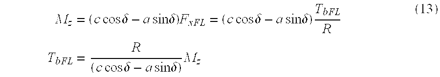
- Each of the above equations (10)-( 13) indicate the torque required from the
respective braking devices 18 a-18 d to induce the control yaw moment (Mz) the braking of a single wheel. For completeness, it is noted that if the denominator of Equations (12) or (13) are zero, the denominator is set to a small value, indicated by TOL, to prevent overflow conditions in the control unit. - B. Torque Saturation
-
Steps electromagnetic retarders 30 is a function of rotor speed and the current supplied to each device. This relationship is illustrated by the curves shown in FIGS. 5 and 6. More particularly, FIG. 5 shows the retarding torque versus current characteristics of the eddy current machine at various rotor speeds between 100 and 1000 RPM. FIG. 6 shows the torque versus rotor speed characteristics of these machines at constant excitation current. As indicated in FIG. 3, if the required torque is less than the estimated torque, thecontrol unit 22 proceeds to Step 46 and calculates the current command according to Equation (19) below. However, if the required torque is greater than the estimated capacity of the actuator, actuator saturation prevents the inducement of the required control yaw moment. - In identifying retarder saturation, the
control unit 22 uses a torque estimation algorithm to determine the estimated torque (Test) which an eddy current machine can generate based upon the rotor speed (ω) and excitation current (i). Previous modeling of electromagnetic retarders, particularly eddy current retarders, have assumed that the braking force or torque varies linearly with speed. In the illustrated embodiment of the present control strategy, the braking torque is more accurately modeled through a quadratic function of rotor speed and excitation current. Thecontrol unit 22 is preferably an open loop controller providing a current optimal torque without the need for a current feedback signal from the retarder thereby eliminating the need for a current sensor. Further, the invention contemplates use of a computationally efficient parametric model control unit to make the YSC system suitable for implementation as production hardware. For example, a parametric model based controller requires less memory in the microprocessor as compared with a look-up table based controller. Hence both the computational and hardware cost can be reduced with a parametric model based controller. - The steady state torque model for the eddy current machines is represented by the following Equation (14).
- T est=ƒ1(ω)+ƒ1(ω)*i+ƒ 2(ω)*i 2 (14)
- where
- T=retarding torque
- i=retarder feedback current
- ƒ1(ω)=a i0 +a i1 ω+a i2ω2
- with
- a i0, ai1, ai2=identified parameters
- ω=rotor speed
- The parameters a ij (where i=0, 1, 2 and j=0,1,2) in Equation (14) are functions of the rotor speed and are estimated from steady state test data. The
solid lines solid line plots lines lines retarder 30 is accurately modeled using a quadratic function of the excitation current and the rotor speed. - If an eddy current machine is used as the primary vehicle braking system, the desired torque in a brake-by-wire system may be tracked in order to meet the driver's brake feel requirements (pedal displacement/force versus vehicle deceleration). It is also desirable, whether the eddy current machine is used as a primary vehicle braking system or as a secondary system in combination with conventional hydraulically actuated friction brakes, to provide accurate torque control in an anti-lock brake system, traction control system, or a vehicle stability control system. The estimated torque produced by the electromagnetic retarder may be calculated based on the retarder torque model discussed in detail below, particularly those sections referring to Equation (14). The accuracy of this estimation is evidenced by the overlayed plots of estimated torque and measured torque for the front and rear wheel retarders (FIGS. 8 and 9, respectively). For completeness it is noted that the measured wheel torque is the net torque at the wheel indicated by a torque sensor. The illustrative tests were designed to minimize the effects of driveline torque and inertia on the measured wheel torque. The test conditions included performing all braking tests in neutral gear, limiting tests to straight line braking with only eddy current machines as the retarding device, and dry asphalt road conditions.
- Using Equation (14), the control unit estimates the torque that an electromagnetic device is capable of generating at a given rotor speed and current. As noted above, if the estimated torque for the desired wheel is less than the torque required pursuant to (10) through (13), then the
control unit 22 determines the amount of torque to be generated by the other wheel on the same side of the vehicle as described below. - C. Multiple Wheels
- When the braking device associated with the desired single wheel is incapable of generating the desired torque prior to saturation, both front and rear wheel braking devices can be used to generate the requested torque. The
control unit 22 is configured to identify when retarder saturation occurs (Steps 90-96) and to generate current commands to the retarders associated with each wheel on a side of the vehicle when the control yaw moment would saturate a single actuator. Equations (15)-(18) below may be used to determine the amount of torque to be generated by each wheel. First, the torque to be generated by the wheel that is most effective at correcting the tracking error (e.g., the rear left wheel for counterclockwise understeering) is set at the estimated maximum or saturation level (Test) calculated above. As illustrated in Steps 100-106 and described below by Equations (15)-(18) the control unit then determines the amount of torque to be generated by the next most effective wheel (e.g., the left front wheel in a counterclockwise understeering condition). - With the above in mind, Equation (15) sets forth an equation for the braking of the front and rear left wheels for a counterclockwise understeered condition.

- Similarly, Equation (16) sets forth an equation for determining the front and rear right wheel braking torques for an understeered vehicle turning clockwise.

- Further, Equation (17) may be used for determining the brake torque for the front and rear right wheels when the vehicle is oversteered and turned counterclockwise.

- Finally, Equation (18) may be used to determine the braking torque for the front and rear left wheels in a clockwise oversteered condition.

- Again, for completeness, it is noted that if the denominator of Equations (15) or (16) in
Steps - 4. Generating Current Command
- Once the torque command has been calculated for each of the selected electromagnetic retarders based on the above equations, the
control unit 22 communicates a current command to the respective retarder, e.g., eddy current machine, in (Step 46) for a given wheel speed (assuming that the retarder is not saturated) and is represented by Equation (19):
- where
- I XY=Current command to FL, FR, RL, or RR eddy current machine
- T bXY=Desired torque for the FL, FR, RL, or RR eddy current machine
- ƒ 0 xy, ƒ1 xy 32 Speed dependent retarder parameters
- Equation (19) is derived from the relationship set forth in Equation (14), which established the quadratic equation as a function of current and rotor speed, with the assumption that the measured current is the same as the commanded current, which is particularly applicable for relatively short time constants as in the illustrated embodiment. More particularly, given the desired torque and measured rotor speed, an analytical quadratic equation solver may be used to obtain the current command from Equation (14) as follows:

- If the second term in the square root symbol is much smaller than unity, the term under square can be expanded in a Taylor series form as follows:

- Using the above expansion, Equation (20) is modified and re-written as follows:

- If the second term in the square bracket of Equation (20) is much smaller than unity, the higher order terms can be omitted. Simplifying the above equation yields Equation (19) which is the proposed open loop control law for an eddy current brake system. The coefficient function ƒ 0 and ƒ1 are estimated through a parameter estimation scheme as mentioned above. Appropriate checks should be performed for coefficient function ƒ1 in order to prevent any possible overflow condition.

- From the above description, it will be appreciated that the YSC system and method of the present invention provides numerous advantages over conventional systems and techniques. By way of example, the present invention utilizes an improved control yaw moment calculation methodology, based on a sliding mode control law based and a lumped mass vehicle model, to minimize tracking error between a desired vehicle yaw rate and an actual vehicle yaw rate. This method provides smoother, more stable, and more robust control so as to minimize undesirable braking device chatter. While the YSC system of the present invention may be used with a variety of braking devices, the disclosed embodiment particularly relates to the use of electromagnetic braking devices, and more particularly to eddy current machines, so as to provide improved response times and undesirable noise, vibration, and harshness (NVH) during operation. Further, the invention accurately models the torque characteristics of the electromagnetic retarders, including through an improved saturation torque estimation technique, that again improves the control and operation of the overall system.
- The foregoing discussion discloses and describes an exemplary embodiment of the present invention. One skilled in the art will readily recognize from such discussion, and from the accompanying drawings and claims that various changes, modifications and variations can be made therein without departing from the true spirit and fair scope of the invention as defined by the following claims.
Claims (35)


Priority Applications (1)
| Application Number | Priority Date | Filing Date | Title |
|---|---|---|---|
| US10/608,906 US7137673B2 (en) | 2003-06-27 | 2003-06-27 | Vehicle yaw stability system and method |
Applications Claiming Priority (1)
| Application Number | Priority Date | Filing Date | Title |
|---|---|---|---|
| US10/608,906 US7137673B2 (en) | 2003-06-27 | 2003-06-27 | Vehicle yaw stability system and method |
Publications (2)
| Publication Number | Publication Date |
|---|---|
| US20040262991A1 true US20040262991A1 (en) | 2004-12-30 |
| US7137673B2 US7137673B2 (en) | 2006-11-21 |
Family
ID=33540713
Family Applications (1)
| Application Number | Title | Priority Date | Filing Date |
|---|---|---|---|
| US10/608,906 Expired - Fee Related US7137673B2 (en) | 2003-06-27 | 2003-06-27 | Vehicle yaw stability system and method |
Country Status (1)
| Country | Link |
|---|---|
| US (1) | US7137673B2 (en) |
Cited By (22)
| Publication number | Priority date | Publication date | Assignee | Title |
|---|---|---|---|---|
| US20050149243A1 (en) * | 2004-01-06 | 2005-07-07 | Ghoneim Youssef A. | Integrating active front steering and vehicle stability brake control |
| US20070067050A1 (en) * | 2005-09-20 | 2007-03-22 | Honeywell International Inc. | Method for soft-computing supervision of dynamical processes with multiple control objectives |
| EP1873033A1 (en) * | 2005-08-05 | 2008-01-02 | HONDA MOTOR CO., Ltd. | Vehicle control device |
| US20080162009A1 (en) * | 2004-12-27 | 2008-07-03 | Kabushikikaisha Equos Research | Wheel Control Device and Control Device |
| US20090171526A1 (en) * | 2005-12-27 | 2009-07-02 | Honda Motor Co., Ltd. | Vehicle Control Device |
| US20110121642A1 (en) * | 2004-03-27 | 2011-05-26 | Martin Heinebrodt | Brake Control System for Motor Vehicles |
| US20120316731A1 (en) * | 2011-06-13 | 2012-12-13 | Continental Automotive Systems, Inc. | Mini-Spare Yaw Mitigation During Driver Braking |
| US20150344013A1 (en) * | 2012-12-21 | 2015-12-03 | Lucas Automotive Gmbh | Electrohydraulic Motor Vehicle Brake System and Method for Operating the Same |
| US20160272067A1 (en) * | 2015-03-18 | 2016-09-22 | E-Aam Driveline Systems Ab | Method for operating an electric drive module |
| CN107463098A (en) * | 2017-09-29 | 2017-12-12 | 中南林业科技大学 | A kind of intelligent carriage method for control speed and device based on quadratic function |
| CN111204332A (en) * | 2020-02-10 | 2020-05-29 | 哈尔滨工业大学 | Sliding mode control method for optimizing vehicle yaw dynamic performance under all working conditions |
| CN111976504A (en) * | 2020-08-26 | 2020-11-24 | 合肥工业大学 | Torque distribution controller, control method and equipment of four-motor-driven automobile and storage medium |
| US10926794B2 (en) * | 2017-10-30 | 2021-02-23 | Toyota Jidosha Kabushiki Kaisha | Vehicular behavior control apparatus |
| CN113396093A (en) * | 2019-03-13 | 2021-09-14 | 雷诺股份公司 | Method for autonomously controlling device mobility |
| CN113805610A (en) * | 2020-06-12 | 2021-12-17 | 中移(苏州)软件技术有限公司 | Trajectory tracking control method and device and storage medium |
| US20220379858A1 (en) * | 2021-06-01 | 2022-12-01 | Toyota Research Institute, Inc. | Purposeful brake-induced wheel lockup for vehicle stability control |
| US20220379855A1 (en) * | 2021-06-01 | 2022-12-01 | Toyota Research Institute, Inc. | Purposeful brake-induced wheel lockup for vehicle stability control in autonomous vehicles |
| US20230094169A1 (en) * | 2021-09-29 | 2023-03-30 | Canoo Technologies Inc. | Emergency motion control for vehicle using steering and torque vectoring |
| WO2023056227A1 (en) * | 2021-09-29 | 2023-04-06 | Canoo Technologies Inc. | Autonomous lateral control of vehicle using direct yaw moment control and path tracking control for self-driving of vehicle with yaw moment distribution |
| US20230124981A1 (en) * | 2021-09-29 | 2023-04-20 | Canoo Technologies Inc. | Path tracking control for self-driving of vehicle with yaw moment distribution |
| CN116985768A (en) * | 2023-09-27 | 2023-11-03 | 万向钱潮股份公司 | Shaft braking force balance control method and device for electromechanical braking system |
| US11845465B2 (en) | 2021-09-29 | 2023-12-19 | Canoo Technologies Inc. | Autonomous lateral control of vehicle using direct yaw moment control |
Families Citing this family (8)
| Publication number | Priority date | Publication date | Assignee | Title |
|---|---|---|---|---|
| JP3868848B2 (en) * | 2002-05-23 | 2007-01-17 | 三菱電機株式会社 | Vehicle state detection device |
| JP4638185B2 (en) * | 2004-08-04 | 2011-02-23 | 富士重工業株式会社 | Vehicle behavior control device |
| JP2006069495A (en) * | 2004-09-06 | 2006-03-16 | Hitachi Ltd | Brake control device |
| US7835836B2 (en) * | 2006-11-08 | 2010-11-16 | Gm Global Technology Operations, Inc. | Methods, systems, and computer program products for calculating a torque overlay command in a steering control system |
| US8521349B2 (en) * | 2010-06-10 | 2013-08-27 | Ford Global Technologies | Vehicle steerability and stability control via independent wheel torque control |
| CN106467111B (en) | 2015-08-20 | 2019-06-07 | 比亚迪股份有限公司 | Vehicle body stable control method, system and automobile |
| JP6585444B2 (en) * | 2015-09-25 | 2019-10-02 | Ntn株式会社 | Vehicle attitude control device |
| US10300897B2 (en) * | 2017-05-15 | 2019-05-28 | Goodrich Corporation | Brake load balance and runway centering techniques |
Citations (40)
| Publication number | Priority date | Publication date | Assignee | Title |
|---|---|---|---|---|
| US4243901A (en) * | 1977-08-31 | 1981-01-06 | Vorona Ilya I | Eddy current machine brake control device |
| US4398111A (en) * | 1982-03-11 | 1983-08-09 | Baylor Company | Eddy current brake |
| US4864173A (en) * | 1988-02-25 | 1989-09-05 | Labavia S.G.E. | Assembly formed by an electromagnetic retarder and its electric supply means |
| US4998593A (en) * | 1989-03-31 | 1991-03-12 | Aisin Seiki Kabushiki Kaisha | Steering and brake controlling system |
| US5187433A (en) * | 1990-10-05 | 1993-02-16 | Labavia S.G.E. | Devices for measuring braking torques generated by electromagnetic retarders, and devices for adjusting such torques |
| US5261503A (en) * | 1990-07-11 | 1993-11-16 | Aisin Seiki Kabushiki Kaisha | Adaptive steering control system |
| US5351795A (en) * | 1992-08-31 | 1994-10-04 | General Motors Corporation | Electronically controlled hydrodynamic retarder with adaptive duty cycles based on decelarations |
| US5482133A (en) * | 1990-07-09 | 1996-01-09 | Nissan Motor Co., Ltd. | Traction control for automotive vehicle |
| US5506770A (en) * | 1993-06-21 | 1996-04-09 | Robert Bosch Gmbh | Directional stability controller |
| US5671143A (en) * | 1994-11-25 | 1997-09-23 | Itt Automotive Europe Gmbh | Driving stability controller with coefficient of friction dependent limitation of the reference yaw rate |
| US5694321A (en) * | 1994-11-25 | 1997-12-02 | Itt Automotive Europe Gmbh | System for integrated driving stability control |
| US5702165A (en) * | 1995-05-17 | 1997-12-30 | Toyota Jidosha Kabushiki Kaisha | Behavior control system of vehicle distinctive of oversteered and understeered conditions |
| US5711024A (en) * | 1994-11-25 | 1998-01-20 | Itt Automotive Europe Gmbh | System for controlling yaw moment based on an estimated coefficient of friction |
| US5711023A (en) * | 1994-11-25 | 1998-01-20 | Itt Automotive Europe Gmbh | System for determining side slip angle |
| US5710705A (en) * | 1994-11-25 | 1998-01-20 | Itt Automotive Europe Gmbh | Method for determining an additional yawing moment based on side slip angle velocity |
| US5710704A (en) * | 1994-11-25 | 1998-01-20 | Itt Automotive Europe Gmbh | System for driving stability control during travel through a curve |
| US5774821A (en) * | 1994-11-25 | 1998-06-30 | Itt Automotive Europe Gmbh | System for driving stability control |
| US5830105A (en) * | 1995-10-11 | 1998-11-03 | Jatco Corporation | Auxiliary brake apparatus |
| US5948027A (en) * | 1996-09-06 | 1999-09-07 | Ford Global Technologies, Inc. | Method for enhancing vehicle stability |
| US5947863A (en) * | 1996-12-20 | 1999-09-07 | Robert Bosch Gmbh | Method and arrangement for controlling the input torque of a transmission |
| US5983149A (en) * | 1991-04-08 | 1999-11-09 | Caterpillar Inc. | Automatic vehicle speed retarding control through actuation of wheel brakes |
| US6003959A (en) * | 1996-12-10 | 1999-12-21 | Unisia Jecs Corporation | Vehicle dynamics control system |
| US6064930A (en) * | 1996-11-13 | 2000-05-16 | Honda Giken Kogyo Kabushiki Kaisha | Yaw moment control system in vehicle |
| US6089680A (en) * | 1997-03-27 | 2000-07-18 | Mazda Motor Corporation | Stability control system for vehicle |
| US6150780A (en) * | 1997-09-04 | 2000-11-21 | General Electric Company | AC motorized wheel control system |
| US6205375B1 (en) * | 1998-12-02 | 2001-03-20 | Nissan Motor Co., Ltd | Vehicle stability control apparatus |
| US6212460B1 (en) * | 1996-09-06 | 2001-04-03 | General Motors Corporation | Brake control system |
| US6216079B1 (en) * | 1998-10-28 | 2001-04-10 | Honda Giken Kogyo Kabushiki Kaisha | Vehicle behavior control system |
| US6219610B1 (en) * | 1998-04-03 | 2001-04-17 | Nissan Motor Co., Ltd. | Turn control system for vehicle |
| US6226587B1 (en) * | 1997-07-11 | 2001-05-01 | Mazda Motor Corporation | Stability control system for automotive vehicle |
| US6233513B1 (en) * | 1997-11-27 | 2001-05-15 | Masato Abe | Method and system for computing a vehicle body slip angle in a vehicle movement control |
| US6267705B1 (en) * | 1996-10-18 | 2001-07-31 | Voith Turbo Gmbh & Co., K.G. | Retarder braking moment adaptation during clutching and gear changing |
| US6272418B1 (en) * | 1997-12-12 | 2001-08-07 | Honda Giken Kogyo Kabushiki Kaisha | Integrated control system of vehicle |
| US6273529B1 (en) * | 1997-12-20 | 2001-08-14 | Continental Teves Ag & Co. Ohg | Method and device for improving the handling characteristics of a vehicle while braking during cornering |
| US6286637B1 (en) * | 1998-03-09 | 2001-09-11 | Kwangju Institute Of Science & Technology | Contactless eddy current brake for cars |
| US6334656B1 (en) * | 1996-06-13 | 2002-01-01 | Honda Giken Kogyo Kabushiki Kaisha | Method and system for controlling the yaw moment of a vehicle |
| USRE37522E1 (en) * | 1988-06-15 | 2002-01-22 | Aisin Seiki Kabushiki Kaisha | Brake controlling system |
| US6349789B1 (en) * | 1997-11-12 | 2002-02-26 | Koyo Seiko Co., Ltd. | Steering device for vehicles |
| US6371234B2 (en) * | 1998-08-10 | 2002-04-16 | Nissan Motor Co., Ltd. | Vehicle stability control apparatus and method |
| US6619760B1 (en) * | 2002-03-07 | 2003-09-16 | Visteon Global Technologies, Inc. | Closed-loop control algorithm for an eddy current braking system |
Family Cites Families (3)
| Publication number | Priority date | Publication date | Assignee | Title |
|---|---|---|---|---|
| FR2714546B1 (en) | 1993-12-23 | 1996-03-01 | Labavia | Eddy current retarder with estimated torque. |
| US6415215B1 (en) | 2000-02-23 | 2002-07-02 | Koyo Seiko Co., Ltd. | Vehicle attitude control apparatus |
| US6668225B2 (en) | 2000-11-29 | 2003-12-23 | Visteon Global Technologies, Inc. | Trailer control system |
-
2003
- 2003-06-27 US US10/608,906 patent/US7137673B2/en not_active Expired - Fee Related
Patent Citations (42)
| Publication number | Priority date | Publication date | Assignee | Title |
|---|---|---|---|---|
| US4243901A (en) * | 1977-08-31 | 1981-01-06 | Vorona Ilya I | Eddy current machine brake control device |
| US4398111A (en) * | 1982-03-11 | 1983-08-09 | Baylor Company | Eddy current brake |
| US4864173A (en) * | 1988-02-25 | 1989-09-05 | Labavia S.G.E. | Assembly formed by an electromagnetic retarder and its electric supply means |
| USRE37522E1 (en) * | 1988-06-15 | 2002-01-22 | Aisin Seiki Kabushiki Kaisha | Brake controlling system |
| US4998593A (en) * | 1989-03-31 | 1991-03-12 | Aisin Seiki Kabushiki Kaisha | Steering and brake controlling system |
| US5482133A (en) * | 1990-07-09 | 1996-01-09 | Nissan Motor Co., Ltd. | Traction control for automotive vehicle |
| US5261503A (en) * | 1990-07-11 | 1993-11-16 | Aisin Seiki Kabushiki Kaisha | Adaptive steering control system |
| US5187433A (en) * | 1990-10-05 | 1993-02-16 | Labavia S.G.E. | Devices for measuring braking torques generated by electromagnetic retarders, and devices for adjusting such torques |
| US5983149A (en) * | 1991-04-08 | 1999-11-09 | Caterpillar Inc. | Automatic vehicle speed retarding control through actuation of wheel brakes |
| US5351795A (en) * | 1992-08-31 | 1994-10-04 | General Motors Corporation | Electronically controlled hydrodynamic retarder with adaptive duty cycles based on decelarations |
| US5506770A (en) * | 1993-06-21 | 1996-04-09 | Robert Bosch Gmbh | Directional stability controller |
| US5694321A (en) * | 1994-11-25 | 1997-12-02 | Itt Automotive Europe Gmbh | System for integrated driving stability control |
| US5711024A (en) * | 1994-11-25 | 1998-01-20 | Itt Automotive Europe Gmbh | System for controlling yaw moment based on an estimated coefficient of friction |
| US5711023A (en) * | 1994-11-25 | 1998-01-20 | Itt Automotive Europe Gmbh | System for determining side slip angle |
| US5710705A (en) * | 1994-11-25 | 1998-01-20 | Itt Automotive Europe Gmbh | Method for determining an additional yawing moment based on side slip angle velocity |
| US5710704A (en) * | 1994-11-25 | 1998-01-20 | Itt Automotive Europe Gmbh | System for driving stability control during travel through a curve |
| US5711025A (en) * | 1994-11-25 | 1998-01-20 | Itt Automotive Europe Gmbh | Driving stability control system with selective brake actuation |
| US5774821A (en) * | 1994-11-25 | 1998-06-30 | Itt Automotive Europe Gmbh | System for driving stability control |
| US5862503A (en) * | 1994-11-25 | 1999-01-19 | Itt Automotive Europe Gmbh | System for driving stability control |
| US5671143A (en) * | 1994-11-25 | 1997-09-23 | Itt Automotive Europe Gmbh | Driving stability controller with coefficient of friction dependent limitation of the reference yaw rate |
| US5702165A (en) * | 1995-05-17 | 1997-12-30 | Toyota Jidosha Kabushiki Kaisha | Behavior control system of vehicle distinctive of oversteered and understeered conditions |
| US5830105A (en) * | 1995-10-11 | 1998-11-03 | Jatco Corporation | Auxiliary brake apparatus |
| US6334656B1 (en) * | 1996-06-13 | 2002-01-01 | Honda Giken Kogyo Kabushiki Kaisha | Method and system for controlling the yaw moment of a vehicle |
| US5948027A (en) * | 1996-09-06 | 1999-09-07 | Ford Global Technologies, Inc. | Method for enhancing vehicle stability |
| US6212460B1 (en) * | 1996-09-06 | 2001-04-03 | General Motors Corporation | Brake control system |
| US6267705B1 (en) * | 1996-10-18 | 2001-07-31 | Voith Turbo Gmbh & Co., K.G. | Retarder braking moment adaptation during clutching and gear changing |
| US6064930A (en) * | 1996-11-13 | 2000-05-16 | Honda Giken Kogyo Kabushiki Kaisha | Yaw moment control system in vehicle |
| US6003959A (en) * | 1996-12-10 | 1999-12-21 | Unisia Jecs Corporation | Vehicle dynamics control system |
| US5947863A (en) * | 1996-12-20 | 1999-09-07 | Robert Bosch Gmbh | Method and arrangement for controlling the input torque of a transmission |
| US6089680A (en) * | 1997-03-27 | 2000-07-18 | Mazda Motor Corporation | Stability control system for vehicle |
| US6226587B1 (en) * | 1997-07-11 | 2001-05-01 | Mazda Motor Corporation | Stability control system for automotive vehicle |
| US6150780A (en) * | 1997-09-04 | 2000-11-21 | General Electric Company | AC motorized wheel control system |
| US6349789B1 (en) * | 1997-11-12 | 2002-02-26 | Koyo Seiko Co., Ltd. | Steering device for vehicles |
| US6233513B1 (en) * | 1997-11-27 | 2001-05-15 | Masato Abe | Method and system for computing a vehicle body slip angle in a vehicle movement control |
| US6272418B1 (en) * | 1997-12-12 | 2001-08-07 | Honda Giken Kogyo Kabushiki Kaisha | Integrated control system of vehicle |
| US6273529B1 (en) * | 1997-12-20 | 2001-08-14 | Continental Teves Ag & Co. Ohg | Method and device for improving the handling characteristics of a vehicle while braking during cornering |
| US6286637B1 (en) * | 1998-03-09 | 2001-09-11 | Kwangju Institute Of Science & Technology | Contactless eddy current brake for cars |
| US6219610B1 (en) * | 1998-04-03 | 2001-04-17 | Nissan Motor Co., Ltd. | Turn control system for vehicle |
| US6371234B2 (en) * | 1998-08-10 | 2002-04-16 | Nissan Motor Co., Ltd. | Vehicle stability control apparatus and method |
| US6216079B1 (en) * | 1998-10-28 | 2001-04-10 | Honda Giken Kogyo Kabushiki Kaisha | Vehicle behavior control system |
| US6205375B1 (en) * | 1998-12-02 | 2001-03-20 | Nissan Motor Co., Ltd | Vehicle stability control apparatus |
| US6619760B1 (en) * | 2002-03-07 | 2003-09-16 | Visteon Global Technologies, Inc. | Closed-loop control algorithm for an eddy current braking system |
Cited By (35)
| Publication number | Priority date | Publication date | Assignee | Title |
|---|---|---|---|---|
| US7698034B2 (en) * | 2004-01-06 | 2010-04-13 | Gm Global Technology Operations, Inc. | Integrating active front steering and vehicle stability brake control |
| US20050149243A1 (en) * | 2004-01-06 | 2005-07-07 | Ghoneim Youssef A. | Integrating active front steering and vehicle stability brake control |
| US9004616B2 (en) * | 2004-03-27 | 2015-04-14 | Robert Bosch Gmbh | Brake control system for motor vehicles |
| US20110121642A1 (en) * | 2004-03-27 | 2011-05-26 | Martin Heinebrodt | Brake Control System for Motor Vehicles |
| US20080162009A1 (en) * | 2004-12-27 | 2008-07-03 | Kabushikikaisha Equos Research | Wheel Control Device and Control Device |
| US7991532B2 (en) * | 2004-12-27 | 2011-08-02 | Equos Research Co., Ltd. | Wheel control device and control device |
| US8271175B2 (en) | 2005-08-05 | 2012-09-18 | Honda Motor Co., Ltd. | Vehicle control device |
| US20090088918A1 (en) * | 2005-08-05 | 2009-04-02 | Honda Motor Co., Ltd. | Vehicle control device |
| EP1873033A4 (en) * | 2005-08-05 | 2008-07-16 | Honda Motor Co Ltd | Vehicle control device |
| EP1873033A1 (en) * | 2005-08-05 | 2008-01-02 | HONDA MOTOR CO., Ltd. | Vehicle control device |
| US7769474B2 (en) | 2005-09-20 | 2010-08-03 | Honeywell International Inc. | Method for soft-computing supervision of dynamical processes with multiple control objectives |
| US20070067050A1 (en) * | 2005-09-20 | 2007-03-22 | Honeywell International Inc. | Method for soft-computing supervision of dynamical processes with multiple control objectives |
| US20090171526A1 (en) * | 2005-12-27 | 2009-07-02 | Honda Motor Co., Ltd. | Vehicle Control Device |
| US8027775B2 (en) * | 2005-12-27 | 2011-09-27 | Honda Motor Co., Ltd. | Vehicle control device |
| US20120316731A1 (en) * | 2011-06-13 | 2012-12-13 | Continental Automotive Systems, Inc. | Mini-Spare Yaw Mitigation During Driver Braking |
| US20150344013A1 (en) * | 2012-12-21 | 2015-12-03 | Lucas Automotive Gmbh | Electrohydraulic Motor Vehicle Brake System and Method for Operating the Same |
| US20160272067A1 (en) * | 2015-03-18 | 2016-09-22 | E-Aam Driveline Systems Ab | Method for operating an electric drive module |
| US9783061B2 (en) * | 2015-03-18 | 2017-10-10 | E-Aam Driveline Systems Ab | Method for operating an electric drive module |
| CN107463098A (en) * | 2017-09-29 | 2017-12-12 | 中南林业科技大学 | A kind of intelligent carriage method for control speed and device based on quadratic function |
| US10926794B2 (en) * | 2017-10-30 | 2021-02-23 | Toyota Jidosha Kabushiki Kaisha | Vehicular behavior control apparatus |
| CN113396093A (en) * | 2019-03-13 | 2021-09-14 | 雷诺股份公司 | Method for autonomously controlling device mobility |
| CN111204332A (en) * | 2020-02-10 | 2020-05-29 | 哈尔滨工业大学 | Sliding mode control method for optimizing vehicle yaw dynamic performance under all working conditions |
| CN113805610A (en) * | 2020-06-12 | 2021-12-17 | 中移(苏州)软件技术有限公司 | Trajectory tracking control method and device and storage medium |
| CN111976504A (en) * | 2020-08-26 | 2020-11-24 | 合肥工业大学 | Torque distribution controller, control method and equipment of four-motor-driven automobile and storage medium |
| US20220379855A1 (en) * | 2021-06-01 | 2022-12-01 | Toyota Research Institute, Inc. | Purposeful brake-induced wheel lockup for vehicle stability control in autonomous vehicles |
| US20220379858A1 (en) * | 2021-06-01 | 2022-12-01 | Toyota Research Institute, Inc. | Purposeful brake-induced wheel lockup for vehicle stability control |
| US11752989B2 (en) * | 2021-06-01 | 2023-09-12 | Toyota Research Institute, Inc. | Purposeful brake-induced wheel lockup for vehicle stability control in autonomous vehicles |
| US11834026B2 (en) * | 2021-06-01 | 2023-12-05 | Toyota Research Institute, Inc. | Purposeful brake-induced wheel lockup for vehicle stability control |
| US20230094169A1 (en) * | 2021-09-29 | 2023-03-30 | Canoo Technologies Inc. | Emergency motion control for vehicle using steering and torque vectoring |
| WO2023056227A1 (en) * | 2021-09-29 | 2023-04-06 | Canoo Technologies Inc. | Autonomous lateral control of vehicle using direct yaw moment control and path tracking control for self-driving of vehicle with yaw moment distribution |
| US20230124981A1 (en) * | 2021-09-29 | 2023-04-20 | Canoo Technologies Inc. | Path tracking control for self-driving of vehicle with yaw moment distribution |
| US11801866B2 (en) * | 2021-09-29 | 2023-10-31 | Canoo Technologies Inc. | Emergency motion control for vehicle using steering and torque vectoring |
| US11845422B2 (en) * | 2021-09-29 | 2023-12-19 | Canoo Technologies Inc. | Path tracking control for self-driving of vehicle with yaw moment distribution |
| US11845465B2 (en) | 2021-09-29 | 2023-12-19 | Canoo Technologies Inc. | Autonomous lateral control of vehicle using direct yaw moment control |
| CN116985768A (en) * | 2023-09-27 | 2023-11-03 | 万向钱潮股份公司 | Shaft braking force balance control method and device for electromechanical braking system |
Also Published As
| Publication number | Publication date |
|---|---|
| US7137673B2 (en) | 2006-11-21 |
Similar Documents
| Publication | Publication Date | Title |
|---|---|---|
| US7137673B2 (en) | Vehicle yaw stability system and method | |
| US6473682B2 (en) | Apparatus and method for estimating maximum road friction coefficient | |
| US6351694B1 (en) | Method for robust estimation of road bank angle | |
| EP0983919B1 (en) | A method for detecting a bank angle experienced by a moving vehicle | |
| JP3633120B2 (en) | Vehicle speed and road friction coefficient estimation device | |
| JP4320406B2 (en) | How to simulate the performance of a vehicle on the road | |
| US6842683B2 (en) | Method of controlling traveling stability of vehicle | |
| EP0225180B1 (en) | Brake control system on turning of motor vehicle | |
| JP3458734B2 (en) | Vehicle motion control device | |
| JP3132371B2 (en) | Vehicle behavior control device | |
| US5742919A (en) | Method and apparatus for dynamically determining a lateral velocity of a motor vehicle | |
| US5471386A (en) | Vehicle traction controller with torque and slip control | |
| US6360150B1 (en) | Device for controlling yawing of vehicle | |
| US8825286B2 (en) | Method and device for determining a center of gravity of a motor vehicle | |
| US6904351B1 (en) | Operating a vehicle control system | |
| US6546324B1 (en) | System and method incorporating dynamic feedforward for integrated control of motor vehicle steering and braking | |
| US20040068358A1 (en) | Anti-lock braking system controller for adjusting slip thresholds on inclines | |
| US11648933B2 (en) | Method for controlling wheel slip of vehicle | |
| US6885931B2 (en) | Control algorithm for a yaw stability management system | |
| JP2007106338A (en) | Vehicle body speed estimating device for vehicle | |
| Bowman et al. | A feasibility study of an automotive slip control braking system | |
| JPH0958449A (en) | Device for estimating wheel characteristics | |
| US11332150B2 (en) | System and method for controlling wheel slip of vehicle | |
| JP3748334B2 (en) | Vehicle attitude control device | |
| EP1285833A2 (en) | Systems and method incorporating dynamic feedforward for integrated control of motor vehicle steering and braking |
Legal Events
| Date | Code | Title | Description |
|---|---|---|---|
| AS | Assignment |
Owner name: VISTEON GLOBAL TECHNOLOGIES, INC., MICHIGAN Free format text: ASSIGNMENT OF ASSIGNORS INTEREST;ASSIGNOR:ANWAR, SOHEL;REEL/FRAME:014320/0784 Effective date: 20030625 |
|
| FEPP | Fee payment procedure |
Free format text: PAYOR NUMBER ASSIGNED (ORIGINAL EVENT CODE: ASPN); ENTITY STATUS OF PATENT OWNER: LARGE ENTITY |
|
| CC | Certificate of correction | ||
| AS | Assignment |
Owner name: JPMORGAN CHASE BANK, N.A., AS ADMINISTRATIVE AGENT Free format text: SECURITY AGREEMENT;ASSIGNOR:VISTEON GLOBAL TECHNOLOGIES, INC.;REEL/FRAME:020497/0733 Effective date: 20060613 |
|
| AS | Assignment |
Owner name: JPMORGAN CHASE BANK, TEXAS Free format text: SECURITY INTEREST;ASSIGNOR:VISTEON GLOBAL TECHNOLOGIES, INC.;REEL/FRAME:022368/0001 Effective date: 20060814 Owner name: JPMORGAN CHASE BANK,TEXAS Free format text: SECURITY INTEREST;ASSIGNOR:VISTEON GLOBAL TECHNOLOGIES, INC.;REEL/FRAME:022368/0001 Effective date: 20060814 |
|
| AS | Assignment |
Owner name: WILMINGTON TRUST FSB, AS ADMINISTRATIVE AGENT, MIN Free format text: ASSIGNMENT OF SECURITY INTEREST IN PATENTS;ASSIGNOR:JPMORGAN CHASE BANK, N.A., AS ADMINISTRATIVE AGENT;REEL/FRAME:022575/0186 Effective date: 20090415 Owner name: WILMINGTON TRUST FSB, AS ADMINISTRATIVE AGENT,MINN Free format text: ASSIGNMENT OF SECURITY INTEREST IN PATENTS;ASSIGNOR:JPMORGAN CHASE BANK, N.A., AS ADMINISTRATIVE AGENT;REEL/FRAME:022575/0186 Effective date: 20090415 |
|
| AS | Assignment |
Owner name: THE BANK OF NEW YORK MELLON, AS ADMINISTRATIVE AGE Free format text: ASSIGNMENT OF PATENT SECURITY INTEREST;ASSIGNOR:JPMORGAN CHASE BANK, N.A., A NATIONAL BANKING ASSOCIATION;REEL/FRAME:022974/0057 Effective date: 20090715 |
|
| REMI | Maintenance fee reminder mailed | ||
| AS | Assignment |
Owner name: VISTEON GLOBAL TECHNOLOGIES, INC., MICHIGAN Free format text: RELEASE BY SECURED PARTY AGAINST SECURITY INTEREST IN PATENTS RECORDED AT REEL 022974 FRAME 0057;ASSIGNOR:THE BANK OF NEW YORK MELLON;REEL/FRAME:025095/0711 Effective date: 20101001 |
|
| AS | Assignment |
Owner name: VISTEON GLOBAL TECHNOLOGIES, INC., MICHIGAN Free format text: RELEASE BY SECURED PARTY AGAINST SECURITY INTEREST IN PATENTS RECORDED AT REEL 022575 FRAME 0186;ASSIGNOR:WILMINGTON TRUST FSB, AS ADMINISTRATIVE AGENT;REEL/FRAME:025105/0201 Effective date: 20101001 |
|
| AS | Assignment |
Owner name: MORGAN STANLEY SENIOR FUNDING, INC., AS AGENT, NEW Free format text: SECURITY AGREEMENT (REVOLVER);ASSIGNORS:VISTEON CORPORATION;VC AVIATION SERVICES, LLC;VISTEON ELECTRONICS CORPORATION;AND OTHERS;REEL/FRAME:025238/0298 Effective date: 20101001 Owner name: MORGAN STANLEY SENIOR FUNDING, INC., AS AGENT, NEW Free format text: SECURITY AGREEMENT;ASSIGNORS:VISTEON CORPORATION;VC AVIATION SERVICES, LLC;VISTEON ELECTRONICS CORPORATION;AND OTHERS;REEL/FRAME:025241/0317 Effective date: 20101007 |
|
| LAPS | Lapse for failure to pay maintenance fees | ||
| STCH | Information on status: patent discontinuation |
Free format text: PATENT EXPIRED DUE TO NONPAYMENT OF MAINTENANCE FEES UNDER 37 CFR 1.362 |
|
| FP | Lapsed due to failure to pay maintenance fee |
Effective date: 20101121 |
|
| AS | Assignment |
Owner name: VISTEON SYSTEMS, LLC, MICHIGAN Free format text: RELEASE BY SECURED PARTY AGAINST SECURITY INTEREST IN PATENTS ON REEL 025241 FRAME 0317;ASSIGNOR:MORGAN STANLEY SENIOR FUNDING, INC.;REEL/FRAME:026178/0412 Effective date: 20110406 Owner name: VISTEON GLOBAL TECHNOLOGIES, INC., MICHIGAN Free format text: RELEASE BY SECURED PARTY AGAINST SECURITY INTEREST IN PATENTS ON REEL 025241 FRAME 0317;ASSIGNOR:MORGAN STANLEY SENIOR FUNDING, INC.;REEL/FRAME:026178/0412 Effective date: 20110406 Owner name: VISTEON EUROPEAN HOLDING, INC., MICHIGAN Free format text: RELEASE BY SECURED PARTY AGAINST SECURITY INTEREST IN PATENTS ON REEL 025241 FRAME 0317;ASSIGNOR:MORGAN STANLEY SENIOR FUNDING, INC.;REEL/FRAME:026178/0412 Effective date: 20110406 Owner name: VISTEON INTERNATIONAL BUSINESS DEVELOPMENT, INC., Free format text: RELEASE BY SECURED PARTY AGAINST SECURITY INTEREST IN PATENTS ON REEL 025241 FRAME 0317;ASSIGNOR:MORGAN STANLEY SENIOR FUNDING, INC.;REEL/FRAME:026178/0412 Effective date: 20110406 Owner name: VC AVIATION SERVICES, LLC, MICHIGAN Free format text: RELEASE BY SECURED PARTY AGAINST SECURITY INTEREST IN PATENTS ON REEL 025241 FRAME 0317;ASSIGNOR:MORGAN STANLEY SENIOR FUNDING, INC.;REEL/FRAME:026178/0412 Effective date: 20110406 Owner name: VISTEON CORPORATION, MICHIGAN Free format text: RELEASE BY SECURED PARTY AGAINST SECURITY INTEREST IN PATENTS ON REEL 025241 FRAME 0317;ASSIGNOR:MORGAN STANLEY SENIOR FUNDING, INC.;REEL/FRAME:026178/0412 Effective date: 20110406 Owner name: VISTEON ELECTRONICS CORPORATION, MICHIGAN Free format text: RELEASE BY SECURED PARTY AGAINST SECURITY INTEREST IN PATENTS ON REEL 025241 FRAME 0317;ASSIGNOR:MORGAN STANLEY SENIOR FUNDING, INC.;REEL/FRAME:026178/0412 Effective date: 20110406 Owner name: VISTEON INTERNATIONAL HOLDINGS, INC., MICHIGAN Free format text: RELEASE BY SECURED PARTY AGAINST SECURITY INTEREST IN PATENTS ON REEL 025241 FRAME 0317;ASSIGNOR:MORGAN STANLEY SENIOR FUNDING, INC.;REEL/FRAME:026178/0412 Effective date: 20110406 Owner name: VISTEON GLOBAL TREASURY, INC., MICHIGAN Free format text: RELEASE BY SECURED PARTY AGAINST SECURITY INTEREST IN PATENTS ON REEL 025241 FRAME 0317;ASSIGNOR:MORGAN STANLEY SENIOR FUNDING, INC.;REEL/FRAME:026178/0412 Effective date: 20110406 |
|
| AS | Assignment |
Owner name: VISTEON CORPORATION, MICHIGAN Free format text: RELEASE OF SECURITY INTEREST IN INTELLECTUAL PROPERTY;ASSIGNOR:MORGAN STANLEY SENIOR FUNDING, INC.;REEL/FRAME:033107/0717 Effective date: 20140409 Owner name: VC AVIATION SERVICES, LLC, MICHIGAN Free format text: RELEASE OF SECURITY INTEREST IN INTELLECTUAL PROPERTY;ASSIGNOR:MORGAN STANLEY SENIOR FUNDING, INC.;REEL/FRAME:033107/0717 Effective date: 20140409 Owner name: VISTEON GLOBAL TECHNOLOGIES, INC., MICHIGAN Free format text: RELEASE OF SECURITY INTEREST IN INTELLECTUAL PROPERTY;ASSIGNOR:MORGAN STANLEY SENIOR FUNDING, INC.;REEL/FRAME:033107/0717 Effective date: 20140409 Owner name: VISTEON INTERNATIONAL HOLDINGS, INC., MICHIGAN Free format text: RELEASE OF SECURITY INTEREST IN INTELLECTUAL PROPERTY;ASSIGNOR:MORGAN STANLEY SENIOR FUNDING, INC.;REEL/FRAME:033107/0717 Effective date: 20140409 Owner name: VISTEON EUROPEAN HOLDINGS, INC., MICHIGAN Free format text: RELEASE OF SECURITY INTEREST IN INTELLECTUAL PROPERTY;ASSIGNOR:MORGAN STANLEY SENIOR FUNDING, INC.;REEL/FRAME:033107/0717 Effective date: 20140409 Owner name: VISTEON SYSTEMS, LLC, MICHIGAN Free format text: RELEASE OF SECURITY INTEREST IN INTELLECTUAL PROPERTY;ASSIGNOR:MORGAN STANLEY SENIOR FUNDING, INC.;REEL/FRAME:033107/0717 Effective date: 20140409 Owner name: VISTEON INTERNATIONAL BUSINESS DEVELOPMENT, INC., Free format text: RELEASE OF SECURITY INTEREST IN INTELLECTUAL PROPERTY;ASSIGNOR:MORGAN STANLEY SENIOR FUNDING, INC.;REEL/FRAME:033107/0717 Effective date: 20140409 Owner name: VISTEON ELECTRONICS CORPORATION, MICHIGAN Free format text: RELEASE OF SECURITY INTEREST IN INTELLECTUAL PROPERTY;ASSIGNOR:MORGAN STANLEY SENIOR FUNDING, INC.;REEL/FRAME:033107/0717 Effective date: 20140409 Owner name: VISTEON GLOBAL TREASURY, INC., MICHIGAN Free format text: RELEASE OF SECURITY INTEREST IN INTELLECTUAL PROPERTY;ASSIGNOR:MORGAN STANLEY SENIOR FUNDING, INC.;REEL/FRAME:033107/0717 Effective date: 20140409 |