US20040049290A1 - Control system and method for controlling an actuated prosthesis - Google Patents
Control system and method for controlling an actuated prosthesis Download PDFInfo
- Publication number
- US20040049290A1 US20040049290A1 US10/600,725 US60072503A US2004049290A1 US 20040049290 A1 US20040049290 A1 US 20040049290A1 US 60072503 A US60072503 A US 60072503A US 2004049290 A1 US2004049290 A1 US 2004049290A1
- Authority
- US
- United States
- Prior art keywords
- data signals
- locomotion
- signal
- plantar pressure
- data
- Prior art date
- Legal status (The legal status is an assumption and is not a legal conclusion. Google has not performed a legal analysis and makes no representation as to the accuracy of the status listed.)
- Granted
Links
Images


Classifications
-
- A—HUMAN NECESSITIES
- A61—MEDICAL OR VETERINARY SCIENCE; HYGIENE
- A61F—FILTERS IMPLANTABLE INTO BLOOD VESSELS; PROSTHESES; DEVICES PROVIDING PATENCY TO, OR PREVENTING COLLAPSING OF, TUBULAR STRUCTURES OF THE BODY, e.g. STENTS; ORTHOPAEDIC, NURSING OR CONTRACEPTIVE DEVICES; FOMENTATION; TREATMENT OR PROTECTION OF EYES OR EARS; BANDAGES, DRESSINGS OR ABSORBENT PADS; FIRST-AID KITS
- A61F2/00—Filters implantable into blood vessels; Prostheses, i.e. artificial substitutes or replacements for parts of the body; Appliances for connecting them with the body; Devices providing patency to, or preventing collapsing of, tubular structures of the body, e.g. stents
- A61F2/50—Prostheses not implantable in the body
- A61F2/68—Operating or control means
- A61F2/70—Operating or control means electrical
-
- A—HUMAN NECESSITIES
- A61—MEDICAL OR VETERINARY SCIENCE; HYGIENE
- A61F—FILTERS IMPLANTABLE INTO BLOOD VESSELS; PROSTHESES; DEVICES PROVIDING PATENCY TO, OR PREVENTING COLLAPSING OF, TUBULAR STRUCTURES OF THE BODY, e.g. STENTS; ORTHOPAEDIC, NURSING OR CONTRACEPTIVE DEVICES; FOMENTATION; TREATMENT OR PROTECTION OF EYES OR EARS; BANDAGES, DRESSINGS OR ABSORBENT PADS; FIRST-AID KITS
- A61F2/00—Filters implantable into blood vessels; Prostheses, i.e. artificial substitutes or replacements for parts of the body; Appliances for connecting them with the body; Devices providing patency to, or preventing collapsing of, tubular structures of the body, e.g. stents
- A61F2/50—Prostheses not implantable in the body
- A61F2/60—Artificial legs or feet or parts thereof
- A61F2/64—Knee joints
- A61F2/642—Polycentric joints, without longitudinal rotation
- A61F2/644—Polycentric joints, without longitudinal rotation of the single-bar or multi-bar linkage type
-
- A—HUMAN NECESSITIES
- A61—MEDICAL OR VETERINARY SCIENCE; HYGIENE
- A61F—FILTERS IMPLANTABLE INTO BLOOD VESSELS; PROSTHESES; DEVICES PROVIDING PATENCY TO, OR PREVENTING COLLAPSING OF, TUBULAR STRUCTURES OF THE BODY, e.g. STENTS; ORTHOPAEDIC, NURSING OR CONTRACEPTIVE DEVICES; FOMENTATION; TREATMENT OR PROTECTION OF EYES OR EARS; BANDAGES, DRESSINGS OR ABSORBENT PADS; FIRST-AID KITS
- A61F2/00—Filters implantable into blood vessels; Prostheses, i.e. artificial substitutes or replacements for parts of the body; Appliances for connecting them with the body; Devices providing patency to, or preventing collapsing of, tubular structures of the body, e.g. stents
- A61F2/50—Prostheses not implantable in the body
- A61F2/60—Artificial legs or feet or parts thereof
- A61F2/66—Feet; Ankle joints
- A61F2/6607—Ankle joints
-
- A—HUMAN NECESSITIES
- A61—MEDICAL OR VETERINARY SCIENCE; HYGIENE
- A61F—FILTERS IMPLANTABLE INTO BLOOD VESSELS; PROSTHESES; DEVICES PROVIDING PATENCY TO, OR PREVENTING COLLAPSING OF, TUBULAR STRUCTURES OF THE BODY, e.g. STENTS; ORTHOPAEDIC, NURSING OR CONTRACEPTIVE DEVICES; FOMENTATION; TREATMENT OR PROTECTION OF EYES OR EARS; BANDAGES, DRESSINGS OR ABSORBENT PADS; FIRST-AID KITS
- A61F2/00—Filters implantable into blood vessels; Prostheses, i.e. artificial substitutes or replacements for parts of the body; Appliances for connecting them with the body; Devices providing patency to, or preventing collapsing of, tubular structures of the body, e.g. stents
- A61F2/50—Prostheses not implantable in the body
- A61F2/60—Artificial legs or feet or parts thereof
- A61F2002/607—Lower legs
-
- A—HUMAN NECESSITIES
- A61—MEDICAL OR VETERINARY SCIENCE; HYGIENE
- A61F—FILTERS IMPLANTABLE INTO BLOOD VESSELS; PROSTHESES; DEVICES PROVIDING PATENCY TO, OR PREVENTING COLLAPSING OF, TUBULAR STRUCTURES OF THE BODY, e.g. STENTS; ORTHOPAEDIC, NURSING OR CONTRACEPTIVE DEVICES; FOMENTATION; TREATMENT OR PROTECTION OF EYES OR EARS; BANDAGES, DRESSINGS OR ABSORBENT PADS; FIRST-AID KITS
- A61F2/00—Filters implantable into blood vessels; Prostheses, i.e. artificial substitutes or replacements for parts of the body; Appliances for connecting them with the body; Devices providing patency to, or preventing collapsing of, tubular structures of the body, e.g. stents
- A61F2/50—Prostheses not implantable in the body
- A61F2/60—Artificial legs or feet or parts thereof
- A61F2/66—Feet; Ankle joints
- A61F2002/6614—Feet
-
- A—HUMAN NECESSITIES
- A61—MEDICAL OR VETERINARY SCIENCE; HYGIENE
- A61F—FILTERS IMPLANTABLE INTO BLOOD VESSELS; PROSTHESES; DEVICES PROVIDING PATENCY TO, OR PREVENTING COLLAPSING OF, TUBULAR STRUCTURES OF THE BODY, e.g. STENTS; ORTHOPAEDIC, NURSING OR CONTRACEPTIVE DEVICES; FOMENTATION; TREATMENT OR PROTECTION OF EYES OR EARS; BANDAGES, DRESSINGS OR ABSORBENT PADS; FIRST-AID KITS
- A61F2/00—Filters implantable into blood vessels; Prostheses, i.e. artificial substitutes or replacements for parts of the body; Appliances for connecting them with the body; Devices providing patency to, or preventing collapsing of, tubular structures of the body, e.g. stents
- A61F2/50—Prostheses not implantable in the body
- A61F2/68—Operating or control means
- A61F2/70—Operating or control means electrical
- A61F2002/701—Operating or control means electrical operated by electrically controlled means, e.g. solenoids or torque motors
-
- A—HUMAN NECESSITIES
- A61—MEDICAL OR VETERINARY SCIENCE; HYGIENE
- A61F—FILTERS IMPLANTABLE INTO BLOOD VESSELS; PROSTHESES; DEVICES PROVIDING PATENCY TO, OR PREVENTING COLLAPSING OF, TUBULAR STRUCTURES OF THE BODY, e.g. STENTS; ORTHOPAEDIC, NURSING OR CONTRACEPTIVE DEVICES; FOMENTATION; TREATMENT OR PROTECTION OF EYES OR EARS; BANDAGES, DRESSINGS OR ABSORBENT PADS; FIRST-AID KITS
- A61F2/00—Filters implantable into blood vessels; Prostheses, i.e. artificial substitutes or replacements for parts of the body; Appliances for connecting them with the body; Devices providing patency to, or preventing collapsing of, tubular structures of the body, e.g. stents
- A61F2/50—Prostheses not implantable in the body
- A61F2/68—Operating or control means
- A61F2/70—Operating or control means electrical
- A61F2002/704—Operating or control means electrical computer-controlled, e.g. robotic control
-
- A—HUMAN NECESSITIES
- A61—MEDICAL OR VETERINARY SCIENCE; HYGIENE
- A61F—FILTERS IMPLANTABLE INTO BLOOD VESSELS; PROSTHESES; DEVICES PROVIDING PATENCY TO, OR PREVENTING COLLAPSING OF, TUBULAR STRUCTURES OF THE BODY, e.g. STENTS; ORTHOPAEDIC, NURSING OR CONTRACEPTIVE DEVICES; FOMENTATION; TREATMENT OR PROTECTION OF EYES OR EARS; BANDAGES, DRESSINGS OR ABSORBENT PADS; FIRST-AID KITS
- A61F2/00—Filters implantable into blood vessels; Prostheses, i.e. artificial substitutes or replacements for parts of the body; Appliances for connecting them with the body; Devices providing patency to, or preventing collapsing of, tubular structures of the body, e.g. stents
- A61F2/50—Prostheses not implantable in the body
- A61F2/68—Operating or control means
- A61F2/70—Operating or control means electrical
- A61F2002/705—Electromagnetic data transfer
-
- A—HUMAN NECESSITIES
- A61—MEDICAL OR VETERINARY SCIENCE; HYGIENE
- A61F—FILTERS IMPLANTABLE INTO BLOOD VESSELS; PROSTHESES; DEVICES PROVIDING PATENCY TO, OR PREVENTING COLLAPSING OF, TUBULAR STRUCTURES OF THE BODY, e.g. STENTS; ORTHOPAEDIC, NURSING OR CONTRACEPTIVE DEVICES; FOMENTATION; TREATMENT OR PROTECTION OF EYES OR EARS; BANDAGES, DRESSINGS OR ABSORBENT PADS; FIRST-AID KITS
- A61F2/00—Filters implantable into blood vessels; Prostheses, i.e. artificial substitutes or replacements for parts of the body; Appliances for connecting them with the body; Devices providing patency to, or preventing collapsing of, tubular structures of the body, e.g. stents
- A61F2/50—Prostheses not implantable in the body
- A61F2/76—Means for assembling, fitting or testing prostheses, e.g. for measuring or balancing, e.g. alignment means
- A61F2002/7615—Measuring means
- A61F2002/762—Measuring means for measuring dimensions, e.g. a distance
-
- A—HUMAN NECESSITIES
- A61—MEDICAL OR VETERINARY SCIENCE; HYGIENE
- A61F—FILTERS IMPLANTABLE INTO BLOOD VESSELS; PROSTHESES; DEVICES PROVIDING PATENCY TO, OR PREVENTING COLLAPSING OF, TUBULAR STRUCTURES OF THE BODY, e.g. STENTS; ORTHOPAEDIC, NURSING OR CONTRACEPTIVE DEVICES; FOMENTATION; TREATMENT OR PROTECTION OF EYES OR EARS; BANDAGES, DRESSINGS OR ABSORBENT PADS; FIRST-AID KITS
- A61F2/00—Filters implantable into blood vessels; Prostheses, i.e. artificial substitutes or replacements for parts of the body; Appliances for connecting them with the body; Devices providing patency to, or preventing collapsing of, tubular structures of the body, e.g. stents
- A61F2/50—Prostheses not implantable in the body
- A61F2/76—Means for assembling, fitting or testing prostheses, e.g. for measuring or balancing, e.g. alignment means
- A61F2002/7615—Measuring means
- A61F2002/7625—Measuring means for measuring angular position
-
- A—HUMAN NECESSITIES
- A61—MEDICAL OR VETERINARY SCIENCE; HYGIENE
- A61F—FILTERS IMPLANTABLE INTO BLOOD VESSELS; PROSTHESES; DEVICES PROVIDING PATENCY TO, OR PREVENTING COLLAPSING OF, TUBULAR STRUCTURES OF THE BODY, e.g. STENTS; ORTHOPAEDIC, NURSING OR CONTRACEPTIVE DEVICES; FOMENTATION; TREATMENT OR PROTECTION OF EYES OR EARS; BANDAGES, DRESSINGS OR ABSORBENT PADS; FIRST-AID KITS
- A61F2/00—Filters implantable into blood vessels; Prostheses, i.e. artificial substitutes or replacements for parts of the body; Appliances for connecting them with the body; Devices providing patency to, or preventing collapsing of, tubular structures of the body, e.g. stents
- A61F2/50—Prostheses not implantable in the body
- A61F2/76—Means for assembling, fitting or testing prostheses, e.g. for measuring or balancing, e.g. alignment means
- A61F2002/7615—Measuring means
- A61F2002/763—Measuring means for measuring spatial position, e.g. global positioning system [GPS]
-
- A—HUMAN NECESSITIES
- A61—MEDICAL OR VETERINARY SCIENCE; HYGIENE
- A61F—FILTERS IMPLANTABLE INTO BLOOD VESSELS; PROSTHESES; DEVICES PROVIDING PATENCY TO, OR PREVENTING COLLAPSING OF, TUBULAR STRUCTURES OF THE BODY, e.g. STENTS; ORTHOPAEDIC, NURSING OR CONTRACEPTIVE DEVICES; FOMENTATION; TREATMENT OR PROTECTION OF EYES OR EARS; BANDAGES, DRESSINGS OR ABSORBENT PADS; FIRST-AID KITS
- A61F2/00—Filters implantable into blood vessels; Prostheses, i.e. artificial substitutes or replacements for parts of the body; Appliances for connecting them with the body; Devices providing patency to, or preventing collapsing of, tubular structures of the body, e.g. stents
- A61F2/50—Prostheses not implantable in the body
- A61F2/76—Means for assembling, fitting or testing prostheses, e.g. for measuring or balancing, e.g. alignment means
- A61F2002/7615—Measuring means
- A61F2002/7635—Measuring means for measuring force, pressure or mechanical tension
-
- A—HUMAN NECESSITIES
- A61—MEDICAL OR VETERINARY SCIENCE; HYGIENE
- A61F—FILTERS IMPLANTABLE INTO BLOOD VESSELS; PROSTHESES; DEVICES PROVIDING PATENCY TO, OR PREVENTING COLLAPSING OF, TUBULAR STRUCTURES OF THE BODY, e.g. STENTS; ORTHOPAEDIC, NURSING OR CONTRACEPTIVE DEVICES; FOMENTATION; TREATMENT OR PROTECTION OF EYES OR EARS; BANDAGES, DRESSINGS OR ABSORBENT PADS; FIRST-AID KITS
- A61F2/00—Filters implantable into blood vessels; Prostheses, i.e. artificial substitutes or replacements for parts of the body; Appliances for connecting them with the body; Devices providing patency to, or preventing collapsing of, tubular structures of the body, e.g. stents
- A61F2/50—Prostheses not implantable in the body
- A61F2/76—Means for assembling, fitting or testing prostheses, e.g. for measuring or balancing, e.g. alignment means
- A61F2002/7615—Measuring means
- A61F2002/7645—Measuring means for measuring torque, e.g. hinge or turning moment, moment of force
-
- A—HUMAN NECESSITIES
- A61—MEDICAL OR VETERINARY SCIENCE; HYGIENE
- A61F—FILTERS IMPLANTABLE INTO BLOOD VESSELS; PROSTHESES; DEVICES PROVIDING PATENCY TO, OR PREVENTING COLLAPSING OF, TUBULAR STRUCTURES OF THE BODY, e.g. STENTS; ORTHOPAEDIC, NURSING OR CONTRACEPTIVE DEVICES; FOMENTATION; TREATMENT OR PROTECTION OF EYES OR EARS; BANDAGES, DRESSINGS OR ABSORBENT PADS; FIRST-AID KITS
- A61F2/00—Filters implantable into blood vessels; Prostheses, i.e. artificial substitutes or replacements for parts of the body; Appliances for connecting them with the body; Devices providing patency to, or preventing collapsing of, tubular structures of the body, e.g. stents
- A61F2/50—Prostheses not implantable in the body
- A61F2/76—Means for assembling, fitting or testing prostheses, e.g. for measuring or balancing, e.g. alignment means
- A61F2002/7615—Measuring means
- A61F2002/7685—Measuring means located on natural or sound-site limbs, e.g. comparison measuring means
Definitions
- the present invention relates to a control system and a method for controlling an actuated prosthesis.
- This invention is particularly well adapted for controlling an actuated leg prosthesis for above-knee amputees.
- a method for determining a portion of locomotion and a phase of locomotion portion in view of controlling an actuated prosthesis in real time comprising:
- a method for controlling an actuated prosthesis in real time comprising:
- a device for determining a portion of locomotion and a phase of locomotion portion in view of controlling an actuated prosthesis in real time using a plurality of main artificial proprioceptors comprising:
- [0031] means for obtaining a third derivative signal for at least one of the data signals
- a set of first state machines the first state machines being used to select one state among a plurality of possible states for each main artificial proprioceptor with the corresponding data and derivative signals;
- [0033] means for generating the phase of locomotion portion using the states of the main artificial proprioceptors
- a second state machine the second state means being used to select the portion of locomotion among a plurality of possible portions of locomotion using events associated to the data signals.
- a control system for controlling an actuated prosthesis in real time comprising:
- a set of first state machines the first state machines being used to select one state among a plurality of possible states for each main artificial proprioceptor with the corresponding data and derivative signals;
- [0040] means for generating the phase of locomotion portion using the states of the main artificial proprioceptors
- a second state machine the second state machine being used to select the portion of locomotion among a plurality of possible portions of locomotion using events associated to data signals;
- [0042] means for calculating a locomotion speed value
- [0043] means for storing a lookup table comprising coefficient values with reference to at least phases of locomotion, portions of locomotion and locomotion speed values;
- [0044] means for determining actual coefficient values from the lookup table using at least the phase of locomotion portion, the portion of locomotion and the locomotion speed value;
- [0045] means for calculating at l ast one dynamic parameter value of the actuated prosthesis using the coefficient values from the lookup table
- [0046] means for converting the dynamic parameter value into an output signal to control th actuated prosthesis.
- FIG. 1 is a block diagram showing the control system in accordance with a preferred embodiment of the present invention.
- FIG. 2 is a perspective view of an example of an actuated prosthesis with a front actuator configuration
- FIG. 3 is a perspective view of an example of an actuated prosthesis with a r ar actuator configuration.
- FIG. 4 is an upper schematic view of an insole provided with plantar pressure sensors.
- FIG. 5 is a cross sectional view of a sensor shown in FIG. 4.
- FIG. 6 is an example of a state machine diagram for the selection of the portion of locomotion.
- FIG. 7 is an example of the phases of locomotion portion within one portion of locomotion (STW) in the state machine diagram shown in FIG. 6.
- FIGS. 8 a to 8 d are examples of four data signals using plantar pressure sensors during typical walking on flat ground.
- FIGS. 9 a to 9 dl give an example of a data signal obtained from a plantar pressure sensor at the calcaneus region and its first three differentials.
- FIGS. 10 a to 10 d give an example of a data signal obtained from a plantar pressure sensor at the metatarsophalangeal (MP) region and its first three differentials.
- FIGS. 11 a to 11 d give an example of the states of a plantar pressure sensor with reference to the data signal and its three first differentiation for a plantar pressure sensor at the calcaneous region.
- FIGS. 12 a to 12 d give an example of the states of a plantar pressure sensor with reference to the data signal and its three first differentiation for a plantar pressure sensor at the metatarsophalangeal (MP) region.
- FIG. 13 is an example of a state machine diagram for the selection of the state of the plantar pressure sensors for the calcaneous region.
- FIG. 14 is an example of a state machine diagram for the selection of the state of the plantar pressure sensors at the metatarsophalangeal (MP) region.
- FIG. 15 is an overall block diagram of the Phase Recognition Module (PRM).
- PRM Phase Recognition Module
- FIG. 16 is a block diagram showing the zero calibration.
- FIG. 17 is a block diagram showing the subject's weight calibration.
- FIG. 18 is a block diagram of the Trajectory Generator (TG).
- FIG. 19 is a block diagram showing the creation of the Trajectory Generator (TG) lookup table.
- FIG. 20 is a graph showing an example of curve representing a Kinematic or kinetic variable for a given portion of locomotion, phase of locomotion portion and subject's speed.
- FIG. 21 is an enlarged representation of FIG. 20.
- CDW Downward Inclined Walking—Cyclical path
- CTW Linear Walking—Cyclical path
- ZV_FRfst x Threshold to consider the first differentiation of from to be positive.
- ZV_SUMfst Threshold to consider the absolute value of the 1 st diff. of sum, to be positive.
- FIG. 1 shows the control system ( 10 ) being combined with an autonomous actuated prosthesis for amputees. It is particularly well adapted for use with an actuated leg prosthesis for above-knee amputees, such as the prostheses ( 12 ) shown in FIGS. 2 and 3. Unlike conventional prostheses, these autonomous actuated prostheses ( 12 ) are designed to supply the mechanical energy necessary to move them by themselves.
- the purpose of the control system ( 10 ) is to provide the required signals allowing to control an actuator ( 14 ). To do so, the control system ( 10 ) is interfaced with the amputee using artificial proprioceptors ( 16 ) to ensure proper coordination between the amputee and the movements of the actuated prosthesis ( 12 ).
- the set of artificial proprioceptors ( 16 ) captures information, in real time, about the dynamics of the amputee's movement and provide that information to the control system ( 10 ).
- the control system ( 10 ) is then used to determine the joint trajectories and the required force or torque that must be applied by the actuator ( 14 ) in order to provide coordinated movements.
- FIG. 2 shows an example of an actuated leg prosthesis ( 12 ) for an above-Knee amputee.
- This prosthesis ( 12 ) is powered by a linear actuator ( 14 ).
- the actuator ( 14 ) moves a knee member ( 20 ) with reference to a trans-tibial member ( 22 ), both of which are pivotally connected using a first pivot axis.
- More sophisticated models may be equipped with a more complex pivot or more than one pivot at that level.
- An artificial foot ( 24 ) is provided under a bottom end of the trans-tibial member ( 22 ).
- the Knee member ( 20 ) comprises a connector ( 25 ) to which a socket ( 26 ) can b attached.
- the sock t ( 26 ) is used to hold the sump of the amputee.
- the design of the knee m mber ( 20 ) is such that the actuator ( 14 ) has an upper end connected to another pivot on th knee member ( 20 ). The bottom end of the actuator ( 14 ) is then connected to a third pivot at the bottom end of the trans-tibial m mber ( 22 ). In use, the actuator ( 14 ) is operated by activating an electrical motor therein.
- the screw ( 28 ) is then moved in or out with reference to a follower ( 30 ), thereby changing the relative angular position between the two movable parts, namely the knee member ( 20 ) and the trans-tibial member ( 22 ).
- FIG. 3 shows an actuated leg prosthesis ( 12 ) in accordance to a rear actuator configuration. This embodiment Is essentially similar to that of FIG. 2 and is illustrated with a different model of actuator ( 14 ).
- the control system ( 10 ) may be used with a leg prosthesis having more than one joint.
- a leg prosthesis having an ankle joint, a metatarsophalangeal joint or a hip joint in addition to a knee joint.
- a osseo-integrated devices could also be used, ensuring a direct attachment between the mechanical component of the prosthesis and the amputee skeleton.
- Other kinds of prostheses may be used as well.
- the information provided by the artificial proprioceptors ( 16 ) are used by the control system ( 10 ) to generate an output signal.
- These output signals are preferably sent to the actuator ( 14 ) via a power drive ( 32 ) which is itself connected to a power supply ( 34 ), for instance a battery, in order to create the movement.
- the power drive ( 32 ) is used to control the amount of power being provided to the actuator ( 14 ). Since the actuator ( 14 ) usually includes an electrical motor, the power drive ( 32 ) generally supplies electrical power to the actuator ( 14 ) to create the movement.
- feedback signals are received from sensors ( 36 ) provided on the prosthesis ( 12 ).
- these feedback signals may indicate the relative position m asured between two movable parts and the torque betwe n them. This option allows the control system ( 10 ) to adequately adjust the output signal. Other types of physical parameters may be monitored as well.
- the control system ( 10 ) shown in FIG. 1 comprises an interface ( 40 ) through which data signals coming from the artificial proprioceptors ( 16 ) are received. They may be received either from an appropriate wiring or from a wireless transmission.
- data signals from the artificial proprioceptors ( 16 ) provided on a healthy leg are advantageously sent through the wireless transmission using an appropriate RF module.
- a simple off-the-shelf RF module with a dedicated specific frequency, such as 916 MHz may be used.
- the use of a RF module with a spread spectrum or frequency hopper is preferable.
- other configurations may be used as well, such as a separate A/D converter, different resolution or sampling values and various combinations of communication link technologies such as wired, wireless, optical, etc.
- the control system ( 10 ) further comprises a part called “Phase Recognition Module” or PRM ( 42 ).
- PRM Phase Recognition Module
- the PRM ( 42 ) is a very important part of the control system ( 10 ) since it is used to determine two important parameters, namely the portion of locomotion and the phase of locomotion portion. These parameters are explained later in the text.
- the PRM ( 42 ) is connected to a Trajectory Generator, or TG ( 44 ), from which dynamic parameters required to control the actuated prosthesis ( 12 ) are calculated to create the output signal.
- a lookup table ( 46 ) is stored in a memory connected to the TG ( 44 ).
- the control system ( 10 ) comprises a regulator ( 48 ) at which the feedback signals are received and the output signal can be adjusted.
- Software residing on an electronic circuit board contains all the above mentioned algorithms enabling the control system ( 10 ) to provide the required signals allowing to control the actuator ( 14 ). More specifically, the software contains the following three modules: the Phase Recognition Module (PRM), the Trajectories Generator (TG) and th Regulator (REG). Of course, any number of auxiliary modules may be added.
- PRM Phase Recognition Module
- TG Trajectories Generator
- REG th Regulator
- the artificial proprioceptors ( 16 ) preferably comprise main artificial proprioceptors and auxiliary artificial proprioceptors.
- the main artificial proprioceptors ar preferably localized plantar pressure sensors which measure the vertical plantar pressure of a specific underfoot area, while the auxiliary artificial proprioceptors are preferably a pair of gyroscopes which measure the angular speed of body segments of the lower extremities and a kinematic sensor which measures the angle of the prosthesis knee joint.
- the plantar pressure sensors are used under both feet, including the artificial foot. It could also be used under two artificial feet if required.
- One of the gyroscope is located at the shank of the normal leg while the other is located on the upper portion of the prosthesis above the knee joint.
- the kinematic sensor it is located at the prosthesis knee joint.
- Other examples of artificial proprioceptors ( 16 ) are neuro-sensors which measure the action potential of motor nerves, myoelectrical electrodes which measure the internal or the external myoelectrical activity of muscles, needle matrix implants which measure the cerebral activity of specific region of the Cerebrum cortex such as motor cortex or any other region indirectly related to the somatic mobility of limbs or any internal or external kinematic and/or kinetic sensors which measure the position and the torque at any joints of the actuated prosthesis.
- additional types of sensors which provide information about various dynamics of human movement may be used.
- FIG. 4 shows a right insole ( 50 ) provided with two plantar pressure sensors ( 16 ) positioned at strategic locations. Their size and position were defined in accordance with the stability and the richness (intensity) of the localized plantar pressure signals provided by certain underfoot areas during locomotion. Experimentation provided numerous data concerning the spatial distribution of foot pressures and more specifically on the Plantar Pressure Maximal Variation (PPMV) during locomotion.
- the PPMV denoted ⁇ max f rij , was defined as the maximum variation of the plantar pressure at a particular point (underfoot area of coordinate i,j) during locomotion.
- the X-Y axis ( 52 ) in FIG. 4 was used to determine the i,j coordinates of each underfoot area.
- a PPMV of a given underfoot area of coordinates ij during a given step denoted event x is defined as stable, through a set of N walking steps, if the ratio of the absolute diff rence between this PPMV and the average PPMV over the set is inferior to a certain value representing the criteria of stability, thus: ( ⁇ ⁇ max ⁇ f r , U ⁇
- n N ⁇ ⁇ n 0 N ⁇ ⁇ max ⁇ f r , U ⁇
- x is the PPMV localized at underfoot area of coordinates i, j during the event x, thus
- K is the number of samples (frames).
- N is the number of steps in the set
- S is the chosen criteria to define if a given PPMV is stable.
- K is the number of samples (frames).
- N is the number of steps 1 n the set
- R is the chosen criteria to define if a given PPMV is rich in information.
- the plantar pressure sensors ( 16 ) are provided in a custom-made insole ( 50 ), preferably in the form of a standard orthopedic insole, that is modified to embed the two sensors ( 16 ) for the measurement of two localized plantar pressures.
- Each sensor ( 16 ), as shown in FIG. 5, is preferably composed of a thin Force-Sensing Resistor (FSR) polymer cell ( 54 ) directly connected to the interface ( 40 ) or indirectly using an intermediary system (not shown), for instance a wireless emitter. Mechanical adapters may be used if FSR cells of appropriate size are not available.
- the FSR cell ( 54 ) has a decreasing electrical resistance in response to an increasing force applied perpendicularly to the surface thereof.
- Each cell ( 54 ) outputs a time variable electrical signal for which the intensity is proportional to the total vertical plantar pressure over its surface area.
- the PRM ( 42 ) ensures, in real-time, the recognition of the phase of locomotion portion and the portion of locomotion of an individual based on the information provided by the artificial proprioceptors ( 16 ).
- the PRM ( 42 ) is said to operate in real time, which means that the computations and other steps are performed continuously and with almost no delay.
- data signals received from individual artificial proprioceptors ( 16 ) can provide enough information in order to control the actuator ( 14 ) of an actuated prosthesis ( 12 ).
- the slope (first derivative), the sign of the concavity (second derivative) and the slope of concavity (third derivative) of the data signals received from plantar pressure sensors, and of combinations of those signals give highly accurate and stable information on the human locomotion.
- the PRM ( 42 ) is then used to decompose of the human locomotion into three levels, namely the states of each artificial proprioceptor ( 16 ), the phase of locomotion portion and the portion of locomotion. This breakdown ensures the proper identification of the complete mobility dynamics of the lower extremities in order to model the human locomotion.
- each main artificial proprioceptor depicts the first level of the locomotion breakdown. This level is defined as the evolution of the main artificial proprioceptors' sensors during the mobility of the lower extremities. Each sensor has its respective state identified from the combination of its data signal and its first three differential signals.
- the main artificial proprioceptors of the preferred embodiment which provid information about localized plantar pressures, it has been discovered xperimentally that the localized plantar pressures signals located at the calcaneous and at the metatarsophalangeal (MP) regions may be grouped into seven and six states respectively.
- the states are preferably as follows:
- the states are preferably as follows:
- phase of locomotion portion is defined as the progression of the subject's mobility within the third level of locomotion breakdown, namely the portion of locomotion.
- This third lev l of the locomotion breakdown defines the type of mobility the subject is currently in, such as, for example, standing, sitting or climbing up stairs.
- Each locomotion portion contains a set of sequential phases illustrating the progression of the subject's mobility within that locomotion portion.
- the phas sequence mapping for each locomotion portion has been identified by experimentation according to the evolution of the state of the localized plantar pr ssures throughout th portion.
- the portions of locomotion are preferably as follows:
- CDW Downward inclined Walking—Cyclical path
- CTW Linear Walking—Cyclical path
- FIG. 6 illustrates an example of the state machine concerning these various portions of locomotion.
- FIG. 7 shows an example of a phase sequence mapping, BTW_ 1 to BTW_ 25 , for the Beginning Path of Linear Walking (BTW) portion of locomotion. All locomotion portions have similar patterns of phase sequence mapping, though the number of phases may vary from one locomotion portion to another. The number of phases depends on the desired granularity of the decomposition of the locomotion portion. The phases are determined experimentally by observing the states of the four localized plantar pressures at specific time intervals, which are determined by the desired granularity. Since a phase is the combination of the states of the four localized plantar pressures, the phase boundary conditions are therefore defined as the combination of each localized plantar pressure state boundary conditions.
- the algorithm uses the state machine approach.
- the algorithm uses a set of events which values define the conditions, or portion boundary conditions, to pass from one locomotion portion to another. These events are identified by experimentation according to the evolution of the localized plantar pressure signals, the complementary signals and their first three differentials, as well as the signals from the auxiliary artificial proprioceptors, when the subject passes from one locomotion portion to another.
- the TG ( 44 ) can be used to calculate one or more dynamic parameter values to be converted to an output signal for the control of the actuator.
- dynamic parameter values are the angular displacement and the torque (or moment of force) at the knee joint of the actuated leg prosthesis ( 12 ). Since these values are given in real time, they provide what is commonly referred to as the ‘system’s trajectory”.
- a mathematical relationship is selected according to the state of the whole system, that is the states of the main artificial proprioceptors, the phase of locomotion portion, the portion of locomotion and the walking speed.
- the angular displacement ⁇ kn and the moment of force m kn are then computed using simple time dependent equations and static characteristics associated with the state of the system, thereby providing the joints trajectory to the knee joint memb r. This process Is repeated throughout the subject's locomotion.
- FIGS. 8 a to 8 d show examples of data signals from the four localized plantar pressure sensors ( 16 ) during a standard walking path at 109.5 steps/minute.
- the four signals, f r1 (t), f r2 (t), f r3 (t) and f r4 (t) correspond to the variation in time of the localized plantar pressure at the calcaneous region of the left foot (FIG. 8 a ), the MP region of the left foot (FIG. 8 b ), the calcaneus region of the right foot (FIG. 8 c ), and the MP region of the right foot (FIG. 8 d ).
- the PRM ( 42 ) uses the first, the second and the third differentials of each of those four localized plantar pressure signals in order to determine the sensors' state. From there, the PRM ( 42 ) will De able to determine the phase of locomotion portion and portion of locomotion of the subject.
- FIGS. 9 a to 9 d and 10 a to 10 d show examples of graphs of localized plantar pressures, as well as their first, second and third differentials, at the calcaneus and MP regions respectively, for a linear walking path of 109.5 steps/minute.
- FIGS. 11 a to 11 d show graphically the state boundary conditions for a typical localized plantar pressure signal, and its first three differentials, at the calcaneous region, while FIGS. 12 a to 12 d do so for the localized plantar pressure signal, and its first two differentials, at the MP region. This shows the relationships between the various data and derivative signals, and the states.
- the PRM ( 42 ) uses a set of first state machines to select, at each increment in time, the current state of each sensor.
- the algorithm uses a set of events who's values define the conditions to pass from one state to another for each of the localized plantar pressures.
- Table 2 lists the events: TABLE 2 List of events used to evaluate the state boundary condition of a localized plantar pressure Event Acronym Description Non-Zero of f rx FR_BIN x Detection of a positive f rx First Differentiation of f rx FRfst_BIN x Detection of positive first differentiation of f rx Second Differentiation of f rx FRsec_BIN x Detection of positive second differentiation of f rx Third Differentiation of f rx FRtrd_BIN x Detection of positive third differentiation of f rx Static f rx STA_BIN x Detection of a static evolution of all f rx
- FIGS. 13 and 14 show, respectively, the diagrams of the state machines used for the detection of the state of the localized plantar pressure at the calcaneous and the MP regions, while Tables 6 and 7 summarize the state boundary conditions between the states of each localized plantar pressure.
- FIG. 15 shows a flow chart that depicts the PRM algorithm, which comprises two main parts, namely the pre-processing of the main artificial proprioceptors signals and the locomotion breakdown, illustrated by blocks 100 and 102 respectively.
- the four localized plantar pressures signals are received from the interface and normalized at block 106 using subject specific calibration values. The four normalized local plantar pressures then go through the pre-processing steps represented by blocks 104 to 118 .
- the four normalized local plantar pressures are filtered to reduce their spectral composition.
- a counter is then initialized at block 108 , which in turn starts a loop comprising blocKs 110 to 116 .
- the first step of the loop, at block 110 consist in the differentiation of the signals.
- the signals resulting from the differentiation step are filtered at block 112 , in order to limit the noise induced during the differential computation, and go through binary formatting at block 114 .
- the algorithm checks if the counter has reached 3 iterations. If so, the algorithm, having computed all first three derivatives of the four normalized local plantar pressures signals, exits the loop to block 102 .
- the algorithm proceeds to block 110 where the counter is increased at block 118 and the loop is repeated, in order to computed the next derivative, by proceeding to block 110 .
- the algorithm enters into the locomotion breakdown part of the algorithm.
- the sequence of steps performed by the locomotion breakdown, represented by block 102 is indicated by the sequence of blocks 120 to 124 . From the four normalized local plantar pressures and their first three derivatives, block 120 determines the states of each sensor while blocks 122 and 124 determine the phase and the portion of locomotion, respectively.
- the normalization step represented by block 106 , consists in levelling the magnitude of the raw data signals according to the anthropomorphic characteristics of the subject such as, in the preferred embodiment, the subject's weight.
- the raw data signals of the four localized plantar pressures are divided by the total magnitude provided by the four sensors during calibration and then provided as the normalized local plantar pressures to block 110 .
- the normalized raw signals of the four localized plantar pressures and their first three differentials are numerically filtered to reduce their spectral composition, as well as to limit the noise induced during the derivative computation.
- the pref rred embodiment of the PRM ( 42 ) uses a 2 nd order numerical filter in which the cut-off frequency, th damping factor and the forward shifting have been set, experimentally, to optimiz the calculation according to the locomotion portion and th type of signal.
- the PRM ( 42 ) may use other types of numerical filters as well, for example a “Buntterworth” filter, as long as the filters dynamic is similar to the one provided by the 2 nd order filter shown thereafter for each locomotion portion. Equation 4 shows the mathematical relationships of the 2 nd order numerical filter which is implemented within the PRM ( 42 ). Table 8 provides examples of filtering parameters for three different portions of locomotion.
- ⁇ n in the none damping natural frequency ⁇ x 1 - 2 ⁇ ⁇ 2 , ⁇ ⁇ 1
- ⁇ n is called the resonance frequency for ⁇ 1 ⁇ is the damping factor
- T sampling rate TABLE 8 Examples of parameters of 2 nd order filters used by the PRM Filtering Parameters Type of Cut-Off Damping Forward Portion of locomotion signal Frequency (F c ) Factor (z) Shifting Linear Walking - Raw 2 0.680 7 Beginning path (BTW) Derivative 3 0.700 3 Linear Walking - Raw 2 0.680 7 Cyclical path (CTW) Derivative 3 0.700 3 Linear Walking - Raw 2 0.680 7 Ending path (ETW) Derivative 3 0.700 3
- the derivatives are obtained by the standard method consisting of numerically differentiating the current and the previous samples of localized plantar pressures.
- the derivatives obtained at block 110 then go through binary formatting at block 114 .
- the result of the binary formatting operation will be a 1′′ if the sign of the derivative is positive, “0” if it is negative. This step facilitates the identification of the sign chang s of the differentiated signals as binary events.
- the PRM ( 42 ) determines the current state of each sensor using state machines such as the ones shown in FIGS. 13 and 14.
- the states of the localized plantar pressures are preferably expressed as a 10-bit words in which each bit corresponds to a specific possible state.
- Tables 9 to 12 list the binary equivalents of each state of the localized plantar pressures at the calcaneous and the MP regions of the left and the right foot. Of course, words of different bit length may be used as well to represent the state of each localized plantar pressure.
- the PRM ( 42 ) generates the phase, which is preferably expressed as the direct binary combination of the states of the four localized plantar pressures.
- the phase can be represented by a 40-bit word wherein the lower part of the lower half word, the higher part of the lower half word, the lower part of the higher half word and the higher part of the higher half word correspond, respectively, to the calcaneous area of the left foot, the MP area of the left foot, the calcaneous area of the right foot and the MP area of the right foot, as represented in Tables 9 to 12.
- Table 13 presents an example of the identification of a phase from the states of the four localized plantar pressures.
- the PRM ( 42 ) selects the portion of locomotion the subject is currently using the state machine shown in FIG. 6. Each portion of locomotion is composed of a sequence of phases.
- Table 14 presents the phases sequence mapping for the Beginning Path of Linear Walking (BTW) locomotion portion corresponding to FIG. 7. This table shows the label, the decimal value and as well the phase boundary conditions of each phase.
- TABLE 14 Example of phases sequence mapping for the locomotion portion labeled “Beginning Path of Linear Walking” (BTW) Phase Boundary Phase Conditions Label Value F r1 F r2 F r3 F r4 BTW_1 275146604800 8 8 8 8 8 8 8 8 8 8 8 8 8 8 8 8 8 8 8 8 8 8 8 8 8 8 8 8 8 8 8 8 8 8 8 8 8 8 8 8 8 8 8 8 8 8 8 8 8 8 8 8 8 8 8 8 8 8 8 8 8 8 8 8 8 8 8 8 8 8 8 8 8 8 8 8 8 8 8 8 8 8 8 8 8 8 8 8 8 8 8 8 8 8 8 8 8 8 8 8 8 8 8 8 8 8 8 8 8 8 8 8 8 8 8 8 8 BTW_2 34493964416 5 7 3 7 BTW_3 2281717888
- Table 15 enumerates a sample of boundary conditions associated with the locomotion portion of the sitting and typical walking on flat ground movements, while Table 3 lists the thresholds used to assess if the aforementioned conditions are met.
- TABLE 15 Example of a list of portion boundary conditions defining specific locomotion portions such as sitting movements (STA-SUP-SIT-SDW- STA locomotion portion) and typical waking on flat ground (STA-BTW-CTW-ETW-STA locomotion portion) Current Next Portion Set of Events Portion STA SWING leg BTW !STATIC_GR leg
- X stands for leg_heel, leg_mp, prosthetic_heel or prosthetic_mp
- Y stands for leg or prosthesis
- the normalization step of block 106 uses specific calibration values. These values are computed the first time a subject uses the actuated prosthesis ( 12 ) or at any other time as may be required. Two calibration values are preferably used: the zero calibration value and the subject's weight calibration value.
- the zero calibration value consists in the measurement of the four localized plantar pressures when no pressure is applied to the sensors, while the subject's weight calibration value is the subject's weight relative to the magnitude of the total response of the sensors.
- the algorithm to obtain the zero calibration value of the sensors is depicted by the flow chart shown in FIG. 16.
- the sequence of steps composing the algorithm is indicated by the sequence of blocks 200 to 222 .
- the algorithm starts with proce ding to block 208
- the average of each localiz d plantar pressures is computed and finally provided as the zero calibration value at block 222 .
- the algorithm to obtain the subject's weight calibration value is depicted by the flow chart shown in FIG. 17.
- the sequence of steps composing th algorithm is indicated by the sequence of blocks 300 to 322 .
- the algorithm starts with the four localized plantar pressures.
- the subject stands up in a comfortable position, feet at shoulder width distance, while maintaining the body in the stance position.
- the subject slowly swings back and forth and then left to right, which initialises a timer at block 306 , which in turn starts a loop comprising blocks 308 , 310 and 312 .
- the algorithm ch cks if the timer has reached 10 seconds, if so, then the algorithm exists the loop to block 320 , if not, the algorithm proceeds to block 310 and records the subject's weight relative to the magnitude of the total response of the sensors Then, at block 312 , th timer is increased and the loop is repeated by proceeding to block 308 .
- the average of each localized plantar pressures is computed and finally provided as the weight calibration value at blocs 322 .
- FIG. 18 shows a flow chart that depicts the TG algorithm used to establish a relationship, in real-time, between the output of the PRM ( 42 ) and localized plantar pressures and the knee joint trajectory.
- the sequence of steps composing the algorithm is indicated by the sequence of blocks 400 to 408 .
- th algorithm receives the normalized localized plantar pressures, the phas of locomotion portion and the portion of the locomotion from the PRM ( 42 ).
- the walking speed of the subject in steps per minute, is obtained from computing the number of frames between two heel strikes, while taking into account the sampling frequency, and is binary formatted.
- f s is the frame sampling frequency (frames/second).
- a heel strike event occurs when:
- the algorithm uses the normalized localized plantar pressures, the phase of locomotion portion, the portion of the locomotion and the subject's spe d in binary format to identify a set of linear normalized static characteristics linking the knee joint kinetic/kinematic parameters with the subject's locomotion in a lookup table.
- the TG ( 44 ) comprises two transformation functions which compute the kinetic/Kinematic parameters at time k, which are the angular displacement ⁇ kn (k) and the moment of force (torque) m kn (k), using the localized plantar pressures and their corresponding mathematical relationships (tim-dependant equations and static characteristics) identified at block 404 .
- the values of the Kinetic/kinematic variables are then provided to the REG ( 48 ) at block 408 .
- the transformation functions used by the TG ( 44 ) at block 406 may generally be represented by a system of equations such as:
- m g h ( k ) M 1 ( ⁇ 1 , ( k ), ⁇ ( k ), ⁇ ( k ))+ M 2 ( ⁇ 2 ( k ), ⁇ ( k ), ⁇ ( k ))+ . . . + M q ⁇ 1 ( ⁇ q ⁇ 1 ( k ), ⁇ ( k ), ⁇ ( k ))+ M q ( ⁇ q ( k ), ⁇ ( k ), ⁇ ( k )) Equation 8
- g [sagittal (sg), frontal (fr), transversal (tr)] is the plane of the motion
- h [hip (hp), knee (kn), ankle (an), metatarsophalangeal (mp)] is the joint
- q is the number of the main artificial proprioceptors' sensors
- ⁇ q is th phenomenological entity related to th locomotion and provided by the main artificial proprioceptors' sensors
- ⁇ q is the transformation function between the phenom nological entity related to the locomotion, the kinematic variables of the lower extremities and the time
- M q is the transformation function between the phenomenological entity related to the locomotion, the kinetic variables of the lower extremities and the time
- ⁇ q is the phenomenological entity related to the locomotion and provided by the main artificial proprioceptors' sensors
- ⁇ (k) ⁇ (P h (k) P r (k), ⁇ (k)) is the state of the whole system (amputee and the AAP) in which K is the current increment
- p h (k) is the phase of the respective locomotion portion
- P r (k) is the locomotion portion
- ⁇ (k) is the walking speed
- ⁇ g,h ( k ) a ( ⁇ ( k ), ⁇ ( k )) ⁇ 1 ( k )+ . . . + a 1.n ( ⁇ ( k ), ⁇ ( k )) ⁇ 1 ( k ) n +a 2.1 ( ⁇ ( k )), ⁇ ( k )) ⁇ 2 ( k )+ . . . + a 2.n ( ⁇ ( k ), ⁇ ( k )) ⁇ 2 ( k ) n + . . . +a q ⁇ 1.3 ( ⁇ ( k )), ⁇ ( k )) ⁇ 2 ( k )+ . . . +a q ⁇ 1.3 ( ⁇ ( k )), ⁇ ( k )) ⁇ 2 ( k )+ . . .
- m g,h ( k ) b ( ⁇ ( k ), ⁇ ( k )) ⁇ 1 ( k )+ . . . + a ( ⁇ ( k ), ⁇ ( k )) ⁇ ( k ) n +b 2.1 ( ⁇ ( k ), ⁇ ( k )) ⁇ 2 ( k )+ . . . + b 2.n ( ⁇ ( k ), ⁇ ( k )) ⁇ 2 ( k ) n + . . .+b q ⁇ 1.1 ( ⁇ ( k ) ⁇ ( k )) ⁇ q ⁇ 1 ( k )+ . . .
- Equation 9 and Equation 10 become:
- ⁇ g,h ( k ) a ( ⁇ ( k ), ⁇ ( k )) ⁇ f r1 ( k )+ a f ( ⁇ ( k ), ⁇ ( k )) ⁇ f r1 ( k ) n +a 2.1 ( ⁇ ( k ), ⁇ ( k )) ⁇ f r2 ( k )+ . . . + a 2,n ( ⁇ ( k ), ⁇ ( k )) ⁇ f r1 ( k ) n +a 3.1 ( ⁇ ( k ), ⁇ ( k )) ⁇ f r3 ( k )+ . . .
- m g,h ( k ) b 1.1 ( ⁇ ( k ), ⁇ ( k )) ⁇ f r1 ( k )+ . . . + b 1,n ( ⁇ ( k ), ⁇ ( k )) ⁇ f r ( k ) n +b 2.1 ( ⁇ ( k ), ⁇ ( k )) ⁇ f 2 ( k ))+ . . . + b 2.n ( ⁇ ( k ), ⁇ ( k )) ⁇ f 2 ( k ) n +b 3.1 ( ⁇ ( k ), ⁇ ( k )) ⁇ f r3 ( k )+ . . .
- FIG. 19 shows a flow chart that depicts th algorithm used to create the TG lookup table.
- the sequence of steps composing the algorithm is indicated by the sequence of blocks 500 to 512 .
- the algorithm measures the selected phenomelogical parameters, which in the pref rred embodiment are the localized plantar pressures, and the kinetc/kinematic parameters ⁇ kn (k) and m kn (k) of a subject.
- the measured pnenomelogical parameters are then normalized in function of the subject's weight
- the static characteristics linking the phenomelogical parameters to the kinetc/kinematic parameters and the time-dependant equations linking to the time are identified and are then normalized at block 506 .
- the mathematical relationships are broken down according to the phenomelogical parameters, the phases of locomotion portion, portions of locomotion, the speed of the subject and in the case were Equation 11 and Equation 12 are linear functions, the binary formatted data signals.
- a polynomial regression is applied, at block 510 , to the mathematical relationships (time-dependant equations and static characteristics) contained in the set.
- the results of the polynomial regressions are stored in the lookup table and are indexed according to the breakdown of block 508 .
- y g,h a 0 +a 1 x 1 +a 2 x 1 2 + . . . +a x n +b 0 +b 1 x 2 +b 2 x 2 2 + . . . +b m x 2 m +. . . ⁇ 0 + ⁇ 1 x 2 + ⁇ 2 x x 2 + . . .
- Y g,h is the estimated kinematic ( ⁇ circumflex over ( ⁇ ) ⁇ g,h ) or kinetic ( ⁇ circumflex over (m) ⁇ g,h ) variables for the g lower extremities joint through the h plan of motion
- g is the lower extremities joint among the following set: hip, knee, ankle and metatarsophalangeal
- h is the plan of motion among the following set: sagittal, frontal and transversal
- x 1 is the j th locomotion related phenomenon, for example the j th localized plantar pressure
- a j,i is the i th coefficient associated the j th locomotion related phenomenon denoted x i
- n j is the order of the polynomial depicting the j th locomotion related phenomenon denoted x
- x is the number of locomotion related ph nomena
- x i may be substituted by the time
- Equation 16 and Equation 17 functions from a set of n samples, obtained from experimentation.
- a sample contains data related to the locomotion related phenomenon along with the corresponding Kinematic ( ⁇ g,h ) or kinetic (m g,h ) variables.
- i s , n s is the index and the number of frames
- x is the time dependant state vector of the system
- x j is the selected locomotion related phenomenon
- ⁇ g,h is the Kinematic variables for the g lower extremities joint through the h plan of motion
- m g,h is the kinetic variable for the g lower extremities joint through the h plan of motion
- a i,j (x) are then present d in th form of a look-up table, as shown in the following example; TABLE 17 Look-up table example a j.l (x) t x a 1.0 a 1.1 . . . a 2.0 a 2.1 . . . a ⁇ .0 a ⁇ .1 . . . a ⁇ .n ⁇ 1 x 1 34.5 23.1 . . . 12.3 92.5 . . . 83.6 52.4 . . . 72.5 2 x 2 23.6 87.5 . . . 64.4 84.9 . . . 93.4 38.6 . . . 28.5 . .
- x is the time dependant state vector of the system
- Table 17 stablishes the relationship between the time dependent state vector of the system, the locomotion related phenomenon and the kinematic and the kinetic variables of the lower extremities joints, which are the following static characteristics:
- the methodology used to identify th parameters a (x) is based on th application of a curve-fitting algorithm to a set of data provided from experimentation on human subjects. This experimentation is p rformed in a laboratory environm nt under controlled conditions, yielding a s t of data in the form of an array, as shown in Table 16.
- the curve-fitting algorithm is used to obtain the parameters a j,i (x) for every given time dependant state vector x. This data is used to construct the look-up table, as shown in Table 17.
- the locomotion related phenomenon is composed of a set of four localized plantar pressures supplied by the main artificial proprioceptors;
- the time dependant state vector is composed of:
- the selected lower extremities joints is the knee joint, which is the joint betwe n the thigh (th) and the shank (sh),
- th time dep ndant state vector further comprises the binary formatted magnitude of the four localized plantar pr ssures as added parameters to further segm nt the curv representing the kinematic ( ⁇ g,h ) or kinetic (m g,h ) variables. This is due to the fact that, as shown by FIG. 20, that for a given portion of locomotion, phase of locomotion portion and subject's speed, the curve representing the kinematic ( ⁇ g,h ) or kin tic (m g,h ) variables cannot efficiently be approximated by a linear function.
- the binary formatted plantar pressures are used to further subdivide the phase of locomotion portion in a number of intervals on which the curve representing the Kinematic ( ⁇ g,h ) or kinetic (m g,h ) variables may be approximated by linear functions.
- FIG. 21 is a close-up view of FIG. 20 where it is shown that the curve representing the Kinematic ( ⁇ g,h ) or Kinetic (m g,h ) variables appear relatively linear on each of the added subdivisions.
- Equation 16 and Equation 17 which are linear functions entails that the time dependant stated vector will further comprise the binary formatted plantar pressures.
- the lookup table contains mathematical relationships that have been normalized in amplitude.
- the TG (44) uses the relative value of the localized plantar pressures instead of the magnitude of the signal. This means that the localized plantar pressures are set into a [0, 1] scal for a specific state of the whole system ⁇ (k). This ensures that the mathematical relationships (time-dependant equations and static characteristics) are independent of the weight of the subject.
- the static characteristics lookup table is valid for any walking speed comprised % Within th operational conditions, which are, in the preferred embodiment, between 84 and 126 steps/min, though the lookup table may be computed for other intervals.
- the Regulator ( 48 ) uses a control law with a similar structure to control algorithms currently employed in numerous commercial or experimental applications.
- Various control laws may be implemented in the Regulator ( 48 ), examples of which are provided below.
- k d is the gain associated to the differential component of the regulator
- k p is the gain associated to the proportional component of the regulator
- k l is the gain associated to the integral component of the regulator
- x o is the trajectory performed by the system
- ⁇ overscore (x) ⁇ is the error between the requested (x l ) and performed trajectory (x o )
- g [sagittal (sg), frontal (fr), transversal (tr)] is the plan of the motion
- h [hip (hp), Knee (kn), ankle (an), metatarsophalangeal (mp)] is the joint
- ⁇ g,h x ( k ) ⁇ g,h x ( k ⁇ 1)+ b o ⁇ overscore (x) ⁇ g,h ( k ⁇ 2)+ b 1 ⁇ overscore (x) ⁇ g,h ( k ⁇ 1)+ b 2 ⁇ overscore (x) ⁇ g,h ( k ) Equation 23
- the Regulator ( 48 ) may use an adaptive PID control law.
- the transfer function of an adaptive PID is the same as that of a conventional PID but th parameters b 2 , b 1 and b 0 are function of the state of the whole system ⁇ (k). From Equation 23, the recurrence equation of the adaptive PID is:
- ⁇ g,h x ( k ) ⁇ g,h x ( k ⁇ 1)+ b 0 ( ⁇ ( k )) ⁇ ⁇ overscore (x) ⁇ g,h ( k ⁇ 2)+ b 1 ⁇ overscore (x) ⁇ g,h ( k ⁇ 1)+ b 2 ( ⁇ ( k )) ⁇ ⁇ overscore (x) ⁇ g,h ( k ) Equation 23
- the Regulator ( 48 ) may use a conventional PID with measured moment, which may be written as:
- f g,h m (k) is the force measured at the joint
- f g,h ⁇ (k) is the set point of the force intended to the joint
- K is the gain yielded by the device between the position and the force set point
- f g,h ⁇ ( k ) f m ( k )+ ⁇ overscore (f) ⁇ g,h ( k ⁇ 1)+ b 0 ⁇ x g,h ( k ⁇ 2)+b 1 ⁇ overscore (x) ⁇ g,h ( k ⁇ 1)+b 2 ⁇ overscore (x) ⁇ g,h ( k ) Equati n 27
Abstract
Description
- The present application claims the benefits of U.S. provisional patent applications No. 60/405,281 filed Aug. 22, 2002; No. 60/424,261 filed Nov. 6, 2002; and No. 60/453,556 filed Mar. 11, 2003, all of which are hereby incorporated by reference.
- The present invention relates to a control system and a method for controlling an actuated prosthesis. This invention is particularly well adapted for controlling an actuated leg prosthesis for above-knee amputees.
- As is well known to control engineers, the automation of complex mechanical systems is not something easy to achieve. Among such systems, conventional powered artificial limbs, or myoelectric prostheses, as they are more commonly referred to, are notorious for having control problems. These conventional prostheses are equipped with basic controllers that artificially mobilize the joints without any interaction from the amputee and are only capable of generating basic motions. Such basic controllers do not take into consideration the dynamic conditions of the working environment, regardless the fact that the prosthesis is required to generate appropriate control within a practical application. They are generally lacking in predictive control strategies necessary to anticipate the artificial limb's response as well as lacking in adaptive regulation enabling the adjustment of the control parameters to the dynamics of the prosthesis. Because human limb mobility is a complex process including voluntary, reflex and random events at the same time, conventional myoel ctric prostheses do not have the capability to interact simultaneously with the human body and the external environment in ord r to have minimal appropriate functioning.
- For exampl, in the case of artificial leg prostheses for above-knee amputees, the complexity of human locomotion resulted in that the technical improvements of conventional leg prostheses have until now been focused on passive mechanisms. This proved to be truly detrimental to the integration of motorized leg prostheses onto the human body. According to amputees, specific conditions of use of conventional leg prostheses, such as repetitive movements and continuous loading, typically entail problems such as increases in metabolic energy expenditures, increases of socket pressure, limitations of locomotion speeds, discrepancies in the locomotion movements, disruptions of postural balance, disruptions of the pelvis-spinal column alignment, and increases in the use of postural clinical rehabilitation programs.
- The major problem remains that the energy used during mobility mainly stems from the user because conventional leg prostheses are not equipped with servomechanisms that enable self-propulsion. This energy compensation has considerable short and long-term negative effects resulting from the daily use of such prostheses. Accordingly, the dynamic role played by the stump during locomotion renders impossible the prolonged wearing of the prostheses as it may create, among other things, several skin problems such as folliculitis, contact dermatitis, edema, cysts, skin shearing, scarring and ulcers. Although these skin problems may b partially alleviated by using a silicon sheath, a complete suction socket, or powder, skin problems remain one of the major preoccupations today.
- As well, the passive nature of the conventional leg prostheses typically leads to movement instability, disrupted movement synchronism and reduced speed of locomotion. Recent developments in the field of energy-saving prosthetic components have partially contributed to improve energy transfer between th amputee and the prosthesis. Nevertheless, the problem of energy expenditure is still not fully resolved and remains the major concern.
- Considering this background, it clearly appears that there was a need to develop an improved control system and a new method for controlling an actuated prosthesis in ord r to fulfill the needs of amputees, in particular those of abov-knee amputees.
- In accordance with one aspect of the present invention, there is provided a method for determining a portion of locomotion and a phase of locomotion portion in view of controlling an actuated prosthesis in real time, the method comprising:
- providing a plurality of main artificial proprioceptors:
- receiving a data signal from each of the main artificial proprioceptors;
- obtaining a first and a second derivative signal for each data signal;
- obtaining a third derivative signal for at least one of the data signals;
- using a set of a first state machines to select one state among a plurality of possible states for each main artificial proprioceptor with the corresponding data and derivative signals;
- generating the phase of locomotion portion using the states of the main artificial proprioceptors: and
- using a second state machine to select the portion of locomotion among a plurality of possible portions of locomotion using events associated to the data signals.
- In accordance with another aspect of the present invention, there is provided a method for controlling an actuated prosthesis in real time, the method comprising:
- providing a plurality of main artificial proprioceptors;
- receiving a data signal from each of the main artificial proprioceptors;
- obtaining a first and a second derivative signal for each data signal;
- obtaining a third derivative signal for at least one of the data signals;
- using a set of first state machin s to select one state among a plurality of possible states for each main artificial proprioceptor with the corresponding data and derivative signals;
- generating the phase of locomotion portion using the states of the main artificial proprioceptors;
- using a second state machine to select the portion of locomotion among a plurality of possible portions of locomotion using events associated to the data signals;
- calculating a locomotion speed value;
- determining coefficient values from a lookup table using at least the phase of locomotion portion, the portion of locomotion and the locomotion speed value;
- calculating at least one dynamic parameter value of the actuated prosthesis using the coefficient values from the lookup table; and
- converting the dynamic parameter value into an output signal to control the actuated prosthesis.
- In accordance with a further aspect of the present invention, there is provided a device for determining a portion of locomotion and a phase of locomotion portion in view of controlling an actuated prosthesis in real time using a plurality of main artificial proprioceptors, the device comprising:
- a data signal input for each of the main artificial proprioceptors;
- means for obtaining a first and a second derivative signal for each data signal;
- means for obtaining a third derivative signal for at least one of the data signals;
- a set of first state machines, the first state machines being used to select one state among a plurality of possible states for each main artificial proprioceptor with the corresponding data and derivative signals;
- means for generating the phase of locomotion portion using the states of the main artificial proprioceptors; and
- a second state machine, the second state means being used to select the portion of locomotion among a plurality of possible portions of locomotion using events associated to the data signals.
- In accordance with a further aspect of the present invention, there is provided a control system for controlling an actuated prosthesis in real time, the system comprising:
- a plurality of main artificial proprioceptors;
- means for obtaining a first and a second derivative signal for each data signal;
- means for obtaining a third derivative signal for at least one of the data signals;
- a set of first state machines, the first state machines being used to select one state among a plurality of possible states for each main artificial proprioceptor with the corresponding data and derivative signals;
- means for generating the phase of locomotion portion using the states of the main artificial proprioceptors;
- a second state machine, the second state machine being used to select the portion of locomotion among a plurality of possible portions of locomotion using events associated to data signals;
- means for calculating a locomotion speed value;
- means for storing a lookup table comprising coefficient values with reference to at least phases of locomotion, portions of locomotion and locomotion speed values;
- means for determining actual coefficient values from the lookup table using at least the phase of locomotion portion, the portion of locomotion and the locomotion speed value;
- means for calculating at l ast one dynamic parameter value of the actuated prosthesis using the coefficient values from the lookup table; and
- means for converting the dynamic parameter value into an output signal to control th actuated prosthesis.
- These and other aspects of the present invention are described in or apparent from the following detailed description, which description is made in conjunction with the accompanying figures.
- FIG. 1 is a block diagram showing the control system in accordance with a preferred embodiment of the present invention.
- FIG. 2 is a perspective view of an example of an actuated prosthesis with a front actuator configuration
- FIG. 3 is a perspective view of an example of an actuated prosthesis with a r ar actuator configuration.
- FIG. 4 is an upper schematic view of an insole provided with plantar pressure sensors.
- FIG. 5 is a cross sectional view of a sensor shown in FIG. 4.
- FIG. 6 is an example of a state machine diagram for the selection of the portion of locomotion.
- FIG. 7 is an example of the phases of locomotion portion within one portion of locomotion (STW) in the state machine diagram shown in FIG. 6.
- FIGS. 8 a to 8 d are examples of four data signals using plantar pressure sensors during typical walking on flat ground.
- FIGS. 9 a to 9 dl give an example of a data signal obtained from a plantar pressure sensor at the calcaneus region and its first three differentials.
- FIGS. 10 a to 10 d give an example of a data signal obtained from a plantar pressure sensor at the metatarsophalangeal (MP) region and its first three differentials.
- FIGS. 11 a to 11 d give an example of the states of a plantar pressure sensor with reference to the data signal and its three first differentiation for a plantar pressure sensor at the calcaneous region.
- FIGS. 12 a to 12 d give an example of the states of a plantar pressure sensor with reference to the data signal and its three first differentiation for a plantar pressure sensor at the metatarsophalangeal (MP) region.
- FIG. 13 is an example of a state machine diagram for the selection of the state of the plantar pressure sensors for the calcaneous region.
- FIG. 14 is an example of a state machine diagram for the selection of the state of the plantar pressure sensors at the metatarsophalangeal (MP) region.
- FIG. 15 is an overall block diagram of the Phase Recognition Module (PRM).
- FIG. 16 is a block diagram showing the zero calibration.
- FIG. 17 is a block diagram showing the subject's weight calibration.
- FIG. 18 is a block diagram of the Trajectory Generator (TG).
- FIG. 19 is a block diagram showing the creation of the Trajectory Generator (TG) lookup table.
- FIG. 20 is a graph showing an example of curve representing a Kinematic or kinetic variable for a given portion of locomotion, phase of locomotion portion and subject's speed.
- FIG. 21 is an enlarged representation of FIG. 20.
- The detailed description and figures refer to the following technical acronyms:
- AED Analog/Digital
- BDW “Downward Inclined Walking—Beginning path” portion of locomotion
- BGD “Going Down Stairs—Beginning path” portion of locomotion
- BGU “Going Up Stairs—Beginning path portion of locomotion
- BTW “Linear Walking—Beginning path” portion of locomotion
- BTW_SWING Detection of typical walking gr_leg during leg swing
- BIJW “Upward Inclined Walking—Beginning path” portion of locomotion
- CDW “Downward Inclined Walking—Cyclical path” portion of locomotion
- CGD Going Down Stairs—Cyclical path” portion of locomotion
- CGU “Going Up Stairs—Cyclical path” portion of locomotion
- CTW “Linear Walking—Cyclical path” portion of locomotion
- CUW “Upward Inclined Walking—Cyclical path” portion of locomotion
- ECW “Cuirve Walking Path” portion of locomotion
- EDW “Downward Inclined Walking—Ending path” portion of locomotion
- EGD “Going Down Stairs—Ending path” portion of locomotion
- EGU “Going Up Stairs—Ending path” portion of locomotion
- ETW “Linear Walking—Ending path” portion of locomotion
- EUW “Upward Inclined Walking—Ending path” portion of locomotion
- FR_BIN x Detection of a positive frx
- FRfst_BIN x Detection of positive first differentiation of frx
- FRsec_BIN x Detection of positive second differentiation of frx
- FRtrd_BIN x Detection of positive third differentiation of frx
- FR_HIGH x Detection of frx level above the STA envelope
- FR_LOW x Detection of fm level between the zero envelope and the STA envelope
- FSR Force Sensing Resistor
- GR_POS y Detection of a positive gry
- MlN_SIT Detection of a minimum time in portion SIT
- MP Metatarsophalangeal
- PID Proportional-Integral-Differential
- PKA_SDW Sit down knee angle
- PKA_ETW End walking knee angle
- PKA_STA Stance knee angle
- PKA_SIT Sit down knee angle
- PKA_SUP_RAMP Standing up knee angle
- PPMV Plantar Pressure Maximal Variation
- PPS Plantar Pressure Sensor
- PRM Phase Recognition Module
- REG Regulator
- RF Radio Frequency
- SDW “Sitting down” portion of locomotion
- SIT “Sitting” portion of locomotion
- STA “Stance of feet” portion of locomotion
- STA_BIN Detection of a static evolution of all f rx
- STATIC_GR y Detection of gry level below the zero angular speed envelope and the zero acceleration envelope
- sum a Localized plantar pressure signal of left foot
- sum b Localized plantar pressure signal of right foot
- sum s Localized plantar pressure signal of both calcaneus
- sum d Localized plantar pressure signal of both MP
- sum e Localized plantar pressure signal of both feet
- SUM_BIN y Non-Zero of sumy
- SUP “Standing Up” portion of locomotion
- SVD Singular Values Decomposition
- SWING y Detection of a swing prior to a foot strike
- TG Trajectory Generator
- XHLSB Heel Loading State Bottom (X=Left (L) or Right (R))
- XHLSM Heel Loading State Middle (X=Left (L) or Right (R))
- XHLST Heel Loading State Top (X=Left (L) or Right (R))
- XHSTA Heel STAtic state (X=Left (L) or Right (R))
- XHUSB Heel Unloading State Bottom (X=Left (L) or Right (R))
- XHUST Heel Unloading State Top (X=Left (L) or Right (R))
- XHZVS Heel Zero Value State (X=Left (L) or Right (R))
- XMLSM MP Loading State Middle (X=Left (L) or Right (R))
- XMLST MP Loading State Top (X=Left (L) or Right (R))
- XMSTA MP STAtic state (X Left (L) or Right (R))
- XMUSB MP Unloading State Bottom (X=Left (L) or Right (R))
- XMUST MP Unloading State Top (X=Left (L) or Right (R))
- XMZVS MP Zero Value State (X=Left (L) or Right (R))
- ZV_FRfst x Threshold to consider the first differentiation of from to be positive.
- ZV_FRsec x Threshold to consider the second differentiation of frx to be positive.
- ZV_FRtrd x Threshold to consider the third differentiation of frx to be positive.
- ZV_FR, Threshold to consider f,, to be positive
- ZV_SUMfst Threshold to consider the absolute value of the 1 st diff. of sum, to be positive.
- ZV_SUMsec Threshold to consider the absolute value of the 2 nd diff. of sums to be positive
- The appended figures show a control system ( 10) in accordance with the preferr d embodiment of the present invention. It should be understood that the present invention is not limited to the illustrated implementation since various changes and modifications may be effected herein without departing from the scope of the appended claims.
- FIG. 1 shows the control system ( 10) being combined with an autonomous actuated prosthesis for amputees. It is particularly well adapted for use with an actuated leg prosthesis for above-knee amputees, such as the prostheses (12) shown in FIGS. 2 and 3. Unlike conventional prostheses, these autonomous actuated prostheses (12) are designed to supply the mechanical energy necessary to move them by themselves. The purpose of the control system (10) is to provide the required signals allowing to control an actuator (14). To do so, the control system (10) is interfaced with the amputee using artificial proprioceptors (16) to ensure proper coordination between the amputee and the movements of the actuated prosthesis (12). The set of artificial proprioceptors (16) captures information, in real time, about the dynamics of the amputee's movement and provide that information to the control system (10). The control system (10) is then used to determine the joint trajectories and the required force or torque that must be applied by the actuator (14) in order to provide coordinated movements.
- FIG. 2 shows an example of an actuated leg prosthesis ( 12) for an above-Knee amputee. This prosthesis (12) is powered by a linear actuator (14). The actuator (14) moves a knee member (20) with reference to a trans-tibial member (22), both of which are pivotally connected using a first pivot axis. More sophisticated models may be equipped with a more complex pivot or more than one pivot at that level.
- An artificial foot ( 24) is provided under a bottom end of the trans-tibial member (22). The Knee member (20) comprises a connector (25) to which a socket (26) can b attached. The sock t (26) is used to hold the sump of the amputee. The design of the knee m mber (20) is such that the actuator (14) has an upper end connected to another pivot on th knee member (20). The bottom end of the actuator (14) is then connected to a third pivot at the bottom end of the trans-tibial m mber (22). In use, the actuator (14) is operated by activating an electrical motor therein. This rotat s, in one direction or another, a screw (28). The screw (28) is then moved in or out with reference to a follower (30), thereby changing the relative angular position between the two movable parts, namely the knee member (20) and the trans-tibial member (22).
- FIG. 3 shows an actuated leg prosthesis ( 12) in accordance to a rear actuator configuration. This embodiment Is essentially similar to that of FIG. 2 and is illustrated with a different model of actuator (14).
- It should be noted that the present invention Is not limited to the mechanical configurations illustrated in FIGS. 2 and 3. The control system ( 10) may be used with a leg prosthesis having more than one joint. For instance, it can be used with a prosthesis having an ankle joint, a metatarsophalangeal joint or a hip joint in addition to a knee joint. Moreover, instead of a conventional socket a osseo-integrated devices could also be used, ensuring a direct attachment between the mechanical component of the prosthesis and the amputee skeleton. Other kinds of prostheses may be used as well.
- Referring back to FIG. 1, the information provided by the artificial proprioceptors ( 16) are used by the control system (10) to generate an output signal. These output signals are preferably sent to the actuator (14) via a power drive (32) which is itself connected to a power supply (34), for instance a battery, in order to create the movement. The power drive (32) is used to control the amount of power being provided to the actuator (14). Since the actuator (14) usually includes an electrical motor, the power drive (32) generally supplies electrical power to the actuator (14) to create the movement.
- Preferably, feedback signals are received from sensors ( 36) provided on the prosthesis (12). In the case of an actuated leg prosthesis (12) such as the one illustrated in FIGS. 2 and 3, these feedback signals may indicate the relative position m asured between two movable parts and the torque betwe n them. This option allows the control system (10) to adequately adjust the output signal. Other types of physical parameters may be monitored as well.
- The control system ( 10) shown in FIG. 1 comprises an interface (40) through which data signals coming from the artificial proprioceptors (16) are received. They may be received either from an appropriate wiring or from a wireless transmission. In the case of actuated leg prostheses for above-knee amputees, data signals from the artificial proprioceptors (16) provided on a healthy leg are advantageously sent through the wireless transmission using an appropriate RF module. For example, a simple off-the-shelf RF module with a dedicated specific frequency, such as 916 MHz, may be used. For a more robust implementation though, the use of a RF module with a spread spectrum or frequency hopper is preferable. Of course, other configurations may be used as well, such as a separate A/D converter, different resolution or sampling values and various combinations of communication link technologies such as wired, wireless, optical, etc.
- The control system ( 10) further comprises a part called “Phase Recognition Module” or PRM (42). The PRM (42) is a very important part of the control system (10) since it is used to determine two important parameters, namely the portion of locomotion and the phase of locomotion portion. These parameters are explained later in the text. The PRM (42) is connected to a Trajectory Generator, or TG (44), from which dynamic parameters required to control the actuated prosthesis (12) are calculated to create the output signal. A lookup table (46) is stored in a memory connected to the TG (44). Moreover, the control system (10) comprises a regulator (48) at which the feedback signals are received and the output signal can be adjusted.
- Software residing on an electronic circuit board contains all the above mentioned algorithms enabling the control system ( 10) to provide the required signals allowing to control the actuator (14). More specifically, the software contains the following three modules: the Phase Recognition Module (PRM), the Trajectories Generator (TG) and th Regulator (REG). Of course, any number of auxiliary modules may be added.
- The artificial proprioceptors ( 16) preferably comprise main artificial proprioceptors and auxiliary artificial proprioceptors. The main artificial proprioceptors ar preferably localized plantar pressure sensors which measure the vertical plantar pressure of a specific underfoot area, while the auxiliary artificial proprioceptors are preferably a pair of gyroscopes which measure the angular speed of body segments of the lower extremities and a kinematic sensor which measures the angle of the prosthesis knee joint. The plantar pressure sensors are used under both feet, including the artificial foot. It could also be used under two artificial feet if required. One of the gyroscope is located at the shank of the normal leg while the other is located on the upper portion of the prosthesis above the knee joint. As for the kinematic sensor, it is located at the prosthesis knee joint. Other examples of artificial proprioceptors (16) are neuro-sensors which measure the action potential of motor nerves, myoelectrical electrodes which measure the internal or the external myoelectrical activity of muscles, needle matrix implants which measure the cerebral activity of specific region of the Cerebrum cortex such as motor cortex or any other region indirectly related to the somatic mobility of limbs or any internal or external kinematic and/or kinetic sensors which measure the position and the torque at any joints of the actuated prosthesis. Of course, depending on the application, additional types of sensors which provide information about various dynamics of human movement may be used.
- FIG. 4 shows a right insole ( 50) provided with two plantar pressure sensors (16) positioned at strategic locations. Their size and position were defined in accordance with the stability and the richness (intensity) of the localized plantar pressure signals provided by certain underfoot areas during locomotion. Experimentation provided numerous data concerning the spatial distribution of foot pressures and more specifically on the Plantar Pressure Maximal Variation (PPMV) during locomotion. The PPMV, denoted Δmaxfrij, was defined as the maximum variation of the plantar pressure at a particular point (underfoot area of coordinate i,j) during locomotion. The X-Y axis (52) in FIG. 4 was used to determine the i,j coordinates of each underfoot area.
- A PPMV of a given underfoot area of coordinates ij during a given step denoted event x, is defined as stable, through a set of N walking steps, if the ratio of the absolute diff rence between this PPMV and the average PPMV over the set is inferior to a certain value representing the criteria of stability, thus:

- where
- Δ max fr,u|x is the PPMV localized at underfoot area of coordinates i, j during the event x, thus
- Δ maxfr,u|x=fx max(k)|k→0 to k−fr,u min (k)|k→0 to k for the event x
- K is the number of samples (frames),
- N is the number of steps in the set,
- S is the chosen criteria to define if a given PPMV is stable.
- A PPMV of a given underfoot area of coordinates i,j during a given step denoted event x, is defined as rich in information, through a set of N walking steps, if the ratio between the PPMV and the average PPMV of the set Is superior to certain value representing the criteria of richness thus:

- where Δ maxfr,u|x is the PPMV localized at underfoot area of coordinates i, j during the event x, thus
- Δ maxfr,u|x=fr,u max(k)|k→0 to k−fr,u min (k)|k→0 to k for the event x
- K is the number of samples (frames),
- N is the number of steps 1 n the set,
- R is the chosen criteria to define if a given PPMV is rich in information.
- It was found by experimentation that the size and the position of plantar pressure sensor are well defined when the criteria are set at 5% and 50% for the stability and the richness PPMV respectively. As a result, it was found that the calcaneus and the Metatarsophalangeal (MP) regions are two regions of the foot sole where the PPMV may be considered as providing a signal that is both stable and rich in information.
- In FIG. 4, the plantar pressure sensors ( 16) are provided in a custom-made insole (50), preferably in the form of a standard orthopedic insole, that is modified to embed the two sensors (16) for the measurement of two localized plantar pressures. Each sensor (16), as shown in FIG. 5, is preferably composed of a thin Force-Sensing Resistor (FSR) polymer cell (54) directly connected to the interface (40) or indirectly using an intermediary system (not shown), for instance a wireless emitter. Mechanical adapters may be used if FSR cells of appropriate size are not available. The FSR cell (54) has a decreasing electrical resistance in response to an increasing force applied perpendicularly to the surface thereof. Each cell (54) outputs a time variable electrical signal for which the intensity is proportional to the total vertical plantar pressure over its surface area.
- The normalized position of the pressure sensors and their size are shown in Table 1, where the length L and the width W are respectively the length and the width of the subject's foot. The coefficients in Table 1 have been obtained by experimentation. A typical diameter for the plantar pressure sensors ( 16) is between 20 and 30 mm
TABLE 1 Normalized position and size of pressure sensors Area Position (X, Y) Size (diameter) Calcaneus (0.51 · W, 0.14 · L) 0.29 · {square root over (L · W)} MP (0.47 · W, 0.76 · L) 0.24 · {square root over (L · W)} - In use, the PRM ( 42) ensures, in real-time, the recognition of the phase of locomotion portion and the portion of locomotion of an individual based on the information provided by the artificial proprioceptors (16). The PRM (42) is said to operate in real time, which means that the computations and other steps are performed continuously and with almost no delay.
- In accordance with the present invention, it was found that data signals received from individual artificial proprioceptors ( 16) can provide enough information in order to control the actuator (14) of an actuated prosthesis (12). For instance, in the cas of plantar pressure sensors, it has been noticed experimentally that the slope (first derivative), the sign of the concavity (second derivative) and the slope of concavity (third derivative) of the data signals received from plantar pressure sensors, and of combinations of those signals, give highly accurate and stable information on the human locomotion. The PRM (42) is then used to decompose of the human locomotion into three levels, namely the states of each artificial proprioceptor (16), the phase of locomotion portion and the portion of locomotion. This breakdown ensures the proper identification of the complete mobility dynamics of the lower extremities in order to model the human locomotion.
- The actual states of each main artificial proprioceptor depict the first level of the locomotion breakdown. This level is defined as the evolution of the main artificial proprioceptors' sensors during the mobility of the lower extremities. Each sensor has its respective state identified from the combination of its data signal and its first three differential signals. For the main artificial proprioceptors of the preferred embodiment, which provid information about localized plantar pressures, it has been discovered xperimentally that the localized plantar pressures signals located at the calcaneous and at the metatarsophalangeal (MP) regions may be grouped into seven and six states respectively.
- For the sensors at the calcaneous regions, the states are preferably as follows:
- XHLSB Heel Loading State Bottom (X Left (L) or Right (R))
- XHI-SM Heel Loading State Middle (X=Left (L) or Right (R))
- XHLST Heel Loading State Top (X=Left (L) or Right (R))
- XHSTA Heel STAtic State (X=Left (L) or Right (R))
- XHUSB Heel Unloading State Bottom (X=Left (L) or Right (R))
- XHUST Heel Unloading State Top (X=Left (L) or Right (R))
- XHZVS Heel Zero Value State (X=Left (L) or Right (R))
- For the sensors at the MP regions, the states are preferably as follows:
- XMLSB MP Loading State Bottom (X Left (L) or Right (R))
- XMLST MP Loading State Top (X=Left (L) or Right (R))
- XMSTA MP STAtic State (X=Left (L) or Right (R))
- XMUSB MP Unloading State Bottom (X=Left (L) or Right (R))
- XMUST MP Unloading State Top (X=Left (L) or Right (R))
- XMZVS MP Zero Value State (X=Left (L) or Right (R))
- Identifying the states at each sensor allows to obtain the second level of the locomotion breakdown, referred to as the phase of locomotion portion. The phase of locomotion portion is defined as the progression of the subject's mobility within the third level of locomotion breakdown, namely the portion of locomotion. This third lev l of the locomotion breakdown defines the type of mobility the subject is currently in, such as, for example, standing, sitting or climbing up stairs. Each locomotion portion contains a set of sequential phases illustrating the progression of the subject's mobility within that locomotion portion. The phas sequence mapping for each locomotion portion has been identified by experimentation according to the evolution of the state of the localized plantar pr ssures throughout th portion.
- The portions of locomotion are preferably as follows:
- BDW “Downward Inclined Walking—Beginning path”
- BGD “Going Down Stairs—Beginning path”
- BGU “Going Up Stairs—Beginning path
- BTW “Linear Walking—Beginning path”
- BUW “Upward Inclined Walking—Beginning path”
- CDW “Downward inclined Walking—Cyclical path”
- CGD “Going Down Stairs—Cyclical path”
- CGU “Going Up Stairs—Cyclical path”
- CTW “Linear Walking—Cyclical path”
- CUW “Upward Inclined Walking—Cyclical path”
- ECW “Curve Walking Path”
- EDW “Downward Inclined Walking—Ending path”
- EGD “Going Down Stairs—Ending path”
- EGU “Going Up Stairs—Ending path”
- ETW “Linear Walking—Ending path”
- EUW “Upward Inclined Walking—Ending path”
- SDW “Sitting down”
- SIT “Sitting”
- STA “Stance of feet”
- SUP “Standing Up”
- FIG. 6 illustrates an example of the state machine concerning these various portions of locomotion.
- FIG. 7 shows an example of a phase sequence mapping, BTW_ 1 to BTW_25, for the Beginning Path of Linear Walking (BTW) portion of locomotion. All locomotion portions have similar patterns of phase sequence mapping, though the number of phases may vary from one locomotion portion to another. The number of phases depends on the desired granularity of the decomposition of the locomotion portion. The phases are determined experimentally by observing the states of the four localized plantar pressures at specific time intervals, which are determined by the desired granularity. Since a phase is the combination of the states of the four localized plantar pressures, the phase boundary conditions are therefore defined as the combination of each localized plantar pressure state boundary conditions.
- For the selection of the portion of locomotion the subject is in, the algorithm uses the state machine approach. For this purpose, the algorithm uses a set of events which values define the conditions, or portion boundary conditions, to pass from one locomotion portion to another. These events are identified by experimentation according to the evolution of the localized plantar pressure signals, the complementary signals and their first three differentials, as well as the signals from the auxiliary artificial proprioceptors, when the subject passes from one locomotion portion to another.
- Having determined the states of the main artificial proprioceptors' sensors, the phase of locomotion portion and portion of locomotion of the subject, the TG ( 44) can be used to calculate one or more dynamic parameter values to be converted to an output signal for the control of the actuator. Examples of dynamic parameter values are the angular displacement and the torque (or moment of force) at the knee joint of the actuated leg prosthesis (12). Since these values are given in real time, they provide what is commonly referred to as the ‘system’s trajectory”. At any time k during the subject's locomotion, a mathematical relationship is selected according to the state of the whole system, that is the states of the main artificial proprioceptors, the phase of locomotion portion, the portion of locomotion and the walking speed. Following which, the angular displacement θkn and the moment of force mkn are then computed using simple time dependent equations and static characteristics associated with the state of the system, thereby providing the joints trajectory to the knee joint memb r. This process Is repeated throughout the subject's locomotion.
- FIGS. 8 a to 8 d show examples of data signals from the four localized plantar pressure sensors (16) during a standard walking path at 109.5 steps/minute. The four signals, fr1(t), fr2(t), fr3(t) and fr4(t), correspond to the variation in time of the localized plantar pressure at the calcaneous region of the left foot (FIG. 8a), the MP region of the left foot (FIG. 8b), the calcaneus region of the right foot (FIG. 8c), and the MP region of the right foot (FIG. 8d).
- In accordance with the present invention, the PRM ( 42) uses the first, the second and the third differentials of each of those four localized plantar pressure signals in order to determine the sensors' state. From there, the PRM (42) will De able to determine the phase of locomotion portion and portion of locomotion of the subject.
- FIGS. 9 a to 9 d and 10 a to 10 d show examples of graphs of localized plantar pressures, as well as their first, second and third differentials, at the calcaneus and MP regions respectively, for a linear walking path of 109.5 steps/minute.
- FIGS. 11 a to 11 d show graphically the state boundary conditions for a typical localized plantar pressure signal, and its first three differentials, at the calcaneous region, while FIGS. 12a to 12 d do so for the localized plantar pressure signal, and its first two differentials, at the MP region. This shows the relationships between the various data and derivative signals, and the states.
- In use, for the detection of the state of the four localized plantar pressures, denoted from where x=[1, 4], the PRM ( 42) uses a set of first state machines to select, at each increment in time, the current state of each sensor. For this purpose, the algorithm uses a set of events who's values define the conditions to pass from one state to another for each of the localized plantar pressures. Table 2 lists the events:
TABLE 2 List of events used to evaluate the state boundary condition of a localized plantar pressure Event Acronym Description Non-Zero of frx FR_BINx Detection of a positive frx First Differentiation of frx FRfst_BINx Detection of positive first differentiation of frx Second Differentiation of frx FRsec_BINx Detection of positive second differentiation of frx Third Differentiation of frx FRtrd_BINx Detection of positive third differentiation of frx Static frx STA_BINx Detection of a static evolution of all frx - The conditions placed on the values of each of the depicted events of Table 2 define when the state machines pass from one state to another for each of the localized plantar pressures. Table 3 lists the thresholds used to assess if the aforementioned conditions are met, in which sum y depicts the five complementary signals, for y=[a, e]as described in Table 4, while Table 5 shows the mathematical form of the events used to evaluate the state boundary condition of the localized plantar pressures
TABLE 3 List of thresholds used to evaluate the state boundary condition of a localized plantar pressure Threshold Acronym Description Positive value of frx ZV_FRx Threshold to consider frx to be positive Positive value of ∂frx∂t ZV_FRfstx Threshold to consider the first differentiation of frx to be positive. Positive value of ∂2frx/∂t2 ZV_FRsecx Threshold to consider the second differentiation of frx to be positive. Positive value of ∂3frx∂t3 ZV_FRtrdx Threshold to consider the third differentiation of frx to be positive. Position value of ∂sumy/∂t ZV_SUMfst Threshold to consider the absolute value of the first differentiation of sumy to be positive. Positive value of ∂2sumy/∂t2 ZV_SUMsec Threshold to consider the absolute value of the second differentiation of sumy to be positive -
TABLE 4 List of complementary signals built from the four localized plantar pressure fr1, fr2, fr3, fr4, Signal Acronym Description Mathematical valu Left foot suma Localized plantar pressure (fr1 + fr2)/2 signal of left foot Right foot sumb Localized plantar pressure (fr3 + fr4)/2 signal of right foot Both sumc Localized plantar pressure (fr1 + fr3)/2 calcaneus signal of both calcaneus Both MP sumd Localized plantar pressure (fr2 + fr4)/2 signal of both MP Both feet sume Localized plantar pressure (fr1 + fr2 + fr3 + fr4)/4 signal of both feet -
TABLE 5 Mathematical formulation of events Acronym Mathematical form FR_BINx 
FRfst_BINx 
FRsec_BINx 
FRtrd_BINx 
STA_BIN 
- FIGS. 13 and 14 show, respectively, the diagrams of the state machines used for the detection of the state of the localized plantar pressure at the calcaneous and the MP regions, while Tables 6 and 7 summarize the state boundary conditions between the states of each localized plantar pressure.
TABLE 6 List of state boundary conditions defining the states of the main artificial proprioceptors at the calcaneus region CURRENT STATE STATE BOUNDARY CONDITIONS NEXT STATE Any state !FR_BINx XHZVS Any state FR_BINx && STA_BINx XHSTA Any state FR_BIN, && !STA_BINx && FRfst_BINx && XHLSB FRsec_BINx && FRtrd_BINx Any state FR_BINx && !STA_BINx && FRfst_BINx && XHLSM FRsec_BINx && !FRtrd_BINx Any state FR_BINx && !STA_BINx && FRfst_BINx && XHLST !FRsec_BINx Any state FR_BINx && !STA_BINx && !FRfst_BINx && XHUST !FRsec_BINx Any state FR_BINx && !STA_BINx && !FRfst_BINx && XHUSB FRsec_BINx -
TABLE 7 List of state boundary conditions defining the states of the main artificial proprioceptors at metatarsophalangeal region CURRENT STATE STATE BOUNDARY CONDITIONS NEXT STATE Any state !FR_BINx XMZVS Any state FR_BINx && STA_BINx XMSTA Any state FR_BINx && !STA_BINx && FRfst_BINx && XMLSB FRsec_BINx Any state FR_BINx && !STA_BINx && FRfst_BINx && XMLST !FRsec_BINx Any state FR_BINx && !STA_BINx && !FRfst_BINx && XMUST !FRsec_BINx Any state FR_BINx && !STA_BINx && !FRfst_BINx && XMUSB FRsec_BINx - FIG. 15 shows a flow chart that depicts the PRM algorithm, which comprises two main parts, namely the pre-processing of the main artificial proprioceptors signals and the locomotion breakdown, illustrated by
blocks block 100, is indicated by the sequence ofblocks 104 to 118. Atblock 104, the four localized plantar pressures signals are received from the interface and normalized at block 106 using subject specific calibration values. The four normalized local plantar pressures then go through the pre-processing steps represented byblocks 104 to 118. Atblock 112, the four normalized local plantar pressures are filtered to reduce their spectral composition. A counter is then initialized at block 108, which in turn starts aloop comprising blocKs 110 to 116. The first step of the loop, atblock 110, consist in the differentiation of the signals. The signals resulting from the differentiation step are filtered atblock 112, in order to limit the noise induced during the differential computation, and go through binary formatting atblock 114. Atblock 116, the algorithm checks if the counter has reached 3 iterations. If so, the algorithm, having computed all first three derivatives of the four normalized local plantar pressures signals, exits the loop to block 102. If not, the algorithm proceeds to block 110 where the counter is increased atblock 118 and the loop is repeated, in order to computed the next derivative, by proceeding to block 110. When the loop exists to block 102, the algorithm enters into the locomotion breakdown part of the algorithm. The sequence of steps performed by the locomotion breakdown, represented byblock 102, is indicated by the sequence ofblocks 120 to 124. From the four normalized local plantar pressures and their first three derivatives, block 120 determines the states of each sensor whileblocks - The normalization step, represented by block 106, consists in levelling the magnitude of the raw data signals according to the anthropomorphic characteristics of the subject such as, in the preferred embodiment, the subject's weight. The raw data signals of the four localized plantar pressures are divided by the total magnitude provided by the four sensors during calibration and then provided as the normalized local plantar pressures to block 110.
- At
block 112 the normalized raw signals of the four localized plantar pressures and their first three differentials are numerically filtered to reduce their spectral composition, as well as to limit the noise induced during the derivative computation. The pref rred embodiment of the PRM (42) uses a 2nd order numerical filter in which the cut-off frequency, th damping factor and the forward shifting have been set, experimentally, to optimiz the calculation according to the locomotion portion and th type of signal. The PRM (42) may use other types of numerical filters as well, for example a “Buntterworth” filter, as long as the filters dynamic is similar to the one provided by the 2nd order filter shown thereafter for each locomotion portion.Equation 4 shows the mathematical relationships of the 2nd order numerical filter which is implemented within the PRM (42). Table 8 provides examples of filtering parameters for three different portions of locomotion. - Laplace Form

- where
- ω n in the none damping natural frequency,

- ω n is called the resonance frequency for η<1 η is the damping factor
- Recursive Form

- where
- a 1=1
- a 2=−2 ·α·β
- a 3=α2
- b 1=0

- α=e ηωT

- β=cos(ω rT)
- ∂=sin(ω rT)
- T=sampling rate
TABLE 8 Examples of parameters of 2nd order filters used by the PRM Filtering Parameters Type of Cut-Off Damping Forward Portion of locomotion signal Frequency (Fc) Factor (z) Shifting Linear Walking - Raw 2 0.680 7 Beginning path (BTW) Derivative 3 0.700 3 Linear Walking - Raw 2 0.680 7 Cyclical path (CTW) Derivative 3 0.700 3 Linear Walking - Raw 2 0.680 7 Ending path (ETW) Derivative 3 0.700 3 - At
block 110, the derivatives are obtained by the standard method consisting of numerically differentiating the current and the previous samples of localized plantar pressures. - The derivatives obtained at
block 110 then go through binary formatting atblock 114. The result of the binary formatting operation will be a 1″ if the sign of the derivative is positive, “0” if it is negative. This step facilitates the identification of the sign chang s of the differentiated signals as binary events. - At
block 120, the PRM (42) determines the current state of each sensor using state machines such as the ones shown in FIGS. 13 and 14. - In the PRM ( 42), the states of the localized plantar pressures are preferably expressed as a 10-bit words in which each bit corresponds to a specific possible state. Tables 9 to 12 list the binary equivalents of each state of the localized plantar pressures at the calcaneous and the MP regions of the left and the right foot. Of course, words of different bit length may be used as well to represent the state of each localized plantar pressure.
TABLE 9 Numerical labels of the states for the localized plantar pressure at calcaneous area of the left foot DECIMAL STATE BINARY LABEL LABEL LHSBS 0 0 0 0 0 0 0 0 0 0 1 0 LHLSB 0 0 0 0 0 0 0 0 0 1 0 1 LHLSM 0 0 0 0 0 0 0 0 1 0 0 2 LHLST 0 0 0 0 0 0 0 1 0 0 0 3 LHUST 0 0 0 0 0 0 1 0 0 0 0 4 LHUSM 0 0 0 0 0 1 0 0 0 0 0 5 LHUSB 0 0 0 0 1 0 0 0 0 0 0 6 LHZVS 0 0 0 1 0 0 0 0 0 0 0 7 LHSTA 0 0 1 0 0 0 0 0 0 0 0 8 -
TABLE 10 Numerical labels of the states for the localized plantar pressure at metatarsaphalangeal area of the left foot DECIMAL STATE BINARY LABEL LABEL LMSBS 0 0 0 0 0 0 0 0 0 0 1 0 LMLSB 0 0 0 0 0 0 0 0 0 1 0 1 LMLSM 0 0 0 0 0 0 0 0 1 0 0 2 LMLST 0 0 0 0 0 0 0 1 0 0 0 3 LMUST 0 0 0 0 0 0 1 0 0 0 0 4 LMUSM 0 0 0 0 0 1 0 0 0 0 0 5 LMUSB 0 0 0 0 1 0 0 0 0 0 0 6 LMZVS 0 0 0 1 0 0 0 0 0 0 0 7 LHSTA 0 0 1 0 0 0 0 0 0 0 0 8 -
TABLE 11 Numerical labels of the states for the localized plantar pressure at calcaneous area at the right foot DECIMAL STATE BINARY LABEL LABEL RHSBS 0 0 0 0 0 0 0 0 0 0 1 0 RHLSB 0 0 0 0 0 0 0 0 0 1 0 1 RHLSM 0 0 0 0 0 0 0 0 1 0 0 2 RHLST 0 0 0 0 0 0 0 1 0 0 0 3 RHUST 0 0 0 0 0 0 1 0 0 0 0 4 RHUSM 0 0 0 0 0 1 0 0 0 0 0 5 RHUSB 0 0 0 0 1 0 0 0 0 0 0 6 RHZVS 0 0 0 1 0 0 0 0 0 0 0 7 RHSTA 0 0 1 0 0 0 0 0 0 0 0 8 -
TABLE 12 Numerical labels of the states for the localized plantar pressure at metatarsophalangeal area of the right foot DECIMAL STATE BINARY LABEL LABEL RMSBS 0 0 0 0 0 0 0 0 0 0 1 0 RMLSB 0 0 0 0 0 0 0 0 0 1 0 1 RMLSM 0 0 0 0 0 0 0 0 1 0 0 2 RMLST 0 0 0 0 0 0 0 1 0 0 0 3 RMUST 0 0 0 0 0 0 1 0 0 0 0 4 RMUSM 0 0 0 0 0 1 0 0 0 0 0 5 RMUSB 0 0 0 0 1 0 0 0 0 0 0 6 RMZVS 0 0 0 1 0 0 0 0 0 0 0 7 RHSTA 0 0 1 0 0 0 0 0 0 0 0 8 - AT
block 122, the PRM (42) generates the phase, which is preferably expressed as the direct binary combination of the states of the four localized plantar pressures. Accordingly, the phase can be represented by a 40-bit word wherein the lower part of the lower half word, the higher part of the lower half word, the lower part of the higher half word and the higher part of the higher half word correspond, respectively, to the calcaneous area of the left foot, the MP area of the left foot, the calcaneous area of the right foot and the MP area of the right foot, as represented in Tables 9 to 12. Table 13 presents an example of the identification of a phase from the states of the four localized plantar pressures.TABLE 13 Identification of a phase from the states of the main artificial proprioceptors State of Localized Plantar Pressure Right Foot Left Foot MP area Calcaneous MP area Calcaneous Corresponding Phase 0000000100 0000010000 0000000001 0000010000 00000001000000010000 00000000010000010000 - At
block 124, the PRM (42) selects the portion of locomotion the subject is currently using the state machine shown in FIG. 6. Each portion of locomotion is composed of a sequence of phases. - Accordingly, Table 14 presents the phases sequence mapping for the Beginning Path of Linear Walking (BTW) locomotion portion corresponding to FIG. 7. This table shows the label, the decimal value and as well the phase boundary conditions of each phase.
TABLE 14 Example of phases sequence mapping for the locomotion portion labeled “Beginning Path of Linear Walking” (BTW) Phase Boundary Phase Conditions Label Value Fr1 Fr2 Fr3 Fr4 BTW_1 275146604800 8 8 8 8 BTW_2 34493964416 5 7 3 7 BTW_3 2281717888 1 7 4 7 BTW_4 4429217920 2 7 5 7 BTW_5 17213489280 4 5 6 7 BTW_6 17314119808 4 7 5 7 BTW_7 34493988992 5 7 5 7 BTW_8 34494087296 5 7 7 7 BTW_9 34361868416 5 1 5 7 BTW_10 34361966720 5 1 7 7 BTW_11 68723802240 6 2 7 7 BTW_12 68727996544 6 3 7 7 BTW_13 68727867520 6 3 1 7 BTW_14 137455732864 7 4 1 7 BTW_15 137455734912 7 4 2 7 BTW_16 137455739008 7 4 3 7 BTW_17 137472512128 7 5 2 7 BTW_18 137472516224 7 5 3 7 BTW_19 137472524416 7 5 4 7 BTW_20 137573187712 7 7 4 7 BTW_21 137573204096 7 7 5 7 BTW_22 137573187586 7 7 4 1 BTW_33 137573203970 7 7 5 1 BTW_24 137573236740 7 7 6 2 BTW_25 137573236744 7 7 6 3 - Table 15 enumerates a sample of boundary conditions associated with the locomotion portion of the sitting and typical walking on flat ground movements, while Table 3 lists the thresholds used to assess if the aforementioned conditions are met.
TABLE 15 Example of a list of portion boundary conditions defining specific locomotion portions such as sitting movements (STA-SUP-SIT-SDW- STA locomotion portion) and typical waking on flat ground (STA-BTW-CTW-ETW-STA locomotion portion) Current Next Portion Set of Events Portion STA SWINGleg BTW !STATIC_GRleg || !STATIC_GRprost FR'LOWprost — heelFR_BINleg — heelBTW_SWING FR_HIGHleg — heelSDW FR_HIGHprost — heelPKA_SDW BTW STATIC_GRleg ETW STATIC_GRprost SUM_BINprost CTW SWINGprost CTW STATIC_GRleg STA STATIC_GRprost FR_BINprost — heelETW FR_BINleg — heelPKA_ETW STATIC_GRleg || STATIC_GRprost ETW PKA_STA STA SDW PKA_SIT SIT PKA_STA STA SIT GR_POSleg SUP MIN_SIT FR_HIGHleg — mpFR_HIGHprost — mpPKA_STA STA SUP !SUM_BINprost SIT !SUM_BINleg PKA_STA STA !PKA_SUP_RAMP SIT -
TABLE 16 Example of a list of events used to evaluate the portion boundary conditions defining specific locomotion portions such as sitting movements (STA-SUP-SIT-SDW-STA locomotion portion) and typical waking on flat ground (STA-BTW-CTW-ETW-STA locomotion portion) Event Acromyn Description Swing occurence SWINGy Detection of a swing prior to a foot strike Non-Zero of frx FR_BINx Detection of a positive frx Low frx FR_LOWx Detection of frx level between the zero envelope and the STA envelope High frx FR_HIGHx Detection of frx level above the STA envelope Static gry STATIC_GRy Detection of gry level below the zero angular speed envelope and the zero acceleration envelope Non-Zero of sumy SUM_BINy Detection of a positive sumy BTW swing BTW_SWING Detection of typical walking gr — leg duringoccurrence leg swing Positive gry GR_POSy Detection of a positive gry Minimum sitting MIN_SIT Detection of a minimum time in portion SIT Sit down knee PKA_SDW Detection of knee angle higher than the angle STA envelope End walking knee PKA_ETW Detection of knee angle lower than the angle STA envelope Stance knee angle PKA_STA Detection of knee angle lower than the STA envelope Sit down knee PKA_SIT Detection of knee angle higher than the angle SIT envelope Standing up knee PKA_SUP_RAMP Detection of standing up knee angle angle evolution - where
- X stands for leg_heel, leg_mp, prosthetic_heel or prosthetic_mp
- Y stands for leg or prosthesis
- The normalization step of block 106 uses specific calibration values. These values are computed the first time a subject uses the actuated prosthesis (12) or at any other time as may be required. Two calibration values are preferably used: the zero calibration value and the subject's weight calibration value. The zero calibration value consists in the measurement of the four localized plantar pressures when no pressure is applied to the sensors, while the subject's weight calibration value is the subject's weight relative to the magnitude of the total response of the sensors.
- The algorithm to obtain the zero calibration value of the sensors is depicted by the flow chart shown in FIG. 16. The sequence of steps composing the algorithm is indicated by the sequence of
blocks 200 to 222. Inblock 200, the algorithm starts with proce ding to block 208 Atblock 220, the average of each localiz d plantar pressures is computed and finally provided as the zero calibration value atblock 222. - In a similar fashion, the algorithm to obtain the subject's weight calibration value is depicted by the flow chart shown in FIG. 17. The sequence of steps composing th algorithm is indicated by the sequence of
blocks 300 to 322. Inblock 300, the algorithm starts with the four localized plantar pressures. Atblock 302, the subject stands up in a comfortable position, feet at shoulder width distance, while maintaining the body in the stance position. Then, atblock 304, the subject slowly swings back and forth and then left to right, which initialises a timer atblock 306, which in turn starts aloop comprising blocks block 308, the algorithm ch cks if the timer has reached 10 seconds, if so, then the algorithm exists the loop to block 320, if not, the algorithm proceeds to block 310 and records the subject's weight relative to the magnitude of the total response of the sensors Then, atblock 312, th timer is increased and the loop is repeated by proceeding to block 308. Atblock 320, the average of each localized plantar pressures is computed and finally provided as the weight calibration value at blocs 322. - FIG. 18 shows a flow chart that depicts the TG algorithm used to establish a relationship, in real-time, between the output of the PRM ( 42) and localized plantar pressures and the knee joint trajectory. The sequence of steps composing the algorithm is indicated by the sequence of
blocks 400 to 408. Atblock 400, th algorithm receives the normalized localized plantar pressures, the phas of locomotion portion and the portion of the locomotion from the PRM (42). Then, atblock 402, the walking speed of the subject, in steps per minute, is obtained from computing the number of frames between two heel strikes, while taking into account the sampling frequency, and is binary formatted. More specifically, the subj ct's speed estimate {circumflex over (x)}v [k] (steps/minute) is obtained from computing the number of frames between two heel strikes sheel [K] (frames/step):
- where f s is the frame sampling frequency (frames/second).
- A heel strike event occurs when:
-
THRESHOLDHEELLOADING <ff [k]−ff , [k−1],f=1,3Equation 6 - At
block 404, the algorithm uses the normalized localized plantar pressures, the phase of locomotion portion, the portion of the locomotion and the subject's spe d in binary format to identify a set of linear normalized static characteristics linking the knee joint kinetic/kinematic parameters with the subject's locomotion in a lookup table. Atblock 406 the TG (44) comprises two transformation functions which compute the kinetic/Kinematic parameters at time k, which are the angular displacement θkn(k) and the moment of force (torque) mkn(k), using the localized plantar pressures and their corresponding mathematical relationships (tim-dependant equations and static characteristics) identified atblock 404. The values of the Kinetic/kinematic variables are then provided to the REG (48) atblock 408. The transformation functions used by the TG (44) atblock 406 may generally be represented by a system of equations such as: - θg,h((k)=Ω1(∂1(k), χ(k), ν(k))+Ω2(∂2(k), χ(k), ν(k))+ . . . +Ωq−1(∂q−1(k), χ(k), ν(k))+Ωq(∂q (k), χ(k), ν(k)) Equation 7
- m g h(k)=M 1(∂1, (k), χ(k), ν(k))+M 2(∂2(k), χ(k), ν(k))+ . . . +M q−1(∂q−1(k), χ(k), ν(k))+M q(∂q(k), χ(k), ν(k)) Equation 8
- where
- g=[sagittal (sg), frontal (fr), transversal (tr)] is the plane of the motion
- h=[hip (hp), knee (kn), ankle (an), metatarsophalangeal (mp)] is the joint
- q is the number of the main artificial proprioceptors' sensors
- ∂ q is th phenomenological entity related to th locomotion and provided by the main artificial proprioceptors' sensors
- Ω qis the transformation function between the phenom nological entity related to the locomotion, the kinematic variables of the lower extremities and the time
- M q is the transformation function between the phenomenological entity related to the locomotion, the kinetic variables of the lower extremities and the time
- ∂ q is the phenomenological entity related to the locomotion and provided by the main artificial proprioceptors' sensors
- χ(k)=Ω(P h(k) Pr(k), ν(k)) is the state of the whole system (amputee and the AAP) in which K is the current increment
- p h(k) is the phase of the respective locomotion portion
- P r(k) is the locomotion portion
- ν(k) is the walking speed
- k is the current increment
- In the case where the TG ( 44) uses polynomial relationships of order n. Equation 7 and Equation 8 become:
- θg,h(k)=a(χ(k), ν(k))·∂1(k)+ . . . +a 1.n(χ(k), ν(k))·∂1(k)n +a 2.1(χ(k)), ν(k)) ∂2(k)+ . . . +a 2.n(χ(k), ν(k))·∂2(k)n + . . . +a q−1.3(χ(k)), ν(k)) ∂2(k)+ . . . +a 2.n(χ(k), ν(k))·∂2(k)n + . . . +a 2.1(χ(k)), ν(k))·∂2(k)+ . . . +a 2.n(χ(k), ν(k))·∂2(k)n Equation 9
- m g,h(k)=b(χ(k), ν(k))·∂1(k)+ . . . +a(χ(k), ν(k))·∂(k)n +b 2.1(χ(k), ν(k))·∂2(k)+ . . . +b 2.n(χ(k), ν(k))·∂2(k)n + . . .+b q−1.1(χ(k)ν(k))·∂q−1 (k)+ . . . +bq−1,n(χ(k), ν(k))·∂q−1(k)+ . . . +b q,1(χ(k), ν(k))·∂q(k)+ . . . +bq,n(χ(k), ν(k))·∂q(k)n
Equati n 10 - where a i,j(ω(k)) and bi,jχ(k)) i=1→q are the coefficients for the state ω(k) of the whole system and the walking speed ν(k) and n is the order of the polynomial
- The preferred embodiment uses four localized plantar pressures, thus Equation 9 and
Equation 10 become: - θg,h(k)=a(χ(k), ν(k))·f r1(k)+a f(χ(k), ν(k))·f r1(k)n +a 2.1(χ(k), ν(k))·f r2(k)+ . . . +a 2,n (χ(k), ν(k))·f r1 (k)n +a 3.1(χ(k), ν(k))·f r3(k)+ . . . +a 3.n(χ(k), ν(k))·f 3(k)n +a 4.1(χ(k), ν(k))·f 3.1(k)+ . . . +a 4.n (χ(k), ν(k))·f r3 (k)n Equation 11
- m g,h(k)=b 1.1(χ(k), ν(k))·f r1 (k)+ . . . +b 1,n(χ(k), ν(k))·f r(k)n +b 2.1(χ(k), ν(k))·f 2 (k))+ . . . +b 2.n(χ(k), ν(k))·f 2(k)n +b 3.1(χ(k), ν(k))·f r3(k)+ . . . +b 3,n(χ(k), ν(k))·f r3(k)n +b 4.1(χ(k), ν(k))·f r3(k)+. . . +b 4,n(χ(k), ν(k))·f r3(k)n
Equation 12 - where a i,j(χ(k)) and bi,j((k)) i=1→q are the coefficients for the state χ(k) of the whole system and the walking speed ν(k) and n is the order of the polynomial
- Since all the kinetic/kinematic parameters θ kn(k) and mkn(k) are computed from non complex mathematical relationships, the computation of the trajectory Is simple and fast and can be calculated by a non-sophisticated electronic circuit board.
- The mathematical relationships (time-dep ndant equations and static characteristics) used in th s −non compl x mathematical relationships are contained in a lookup table referenced at
block 404. FIG. 19 shows a flow chart that depicts th algorithm used to create the TG lookup table. The sequence of steps composing the algorithm is indicated by the sequence ofblocks 500 to 512. Atblock 500, the algorithm measures the selected phenomelogical parameters, which in the pref rred embodiment are the localized plantar pressures, and the kinetc/kinematic parameters θkn(k) and mkn(k) of a subject. The measured pnenomelogical parameters are then normalized in function of the subject's weight Atblock 504, the static characteristics linking the phenomelogical parameters to the kinetc/kinematic parameters and the time-dependant equations linking to the time are identified and are then normalized atblock 506. Then atblock 508, the mathematical relationships (time-dependant equations and static characteristics) are broken down according to the phenomelogical parameters, the phases of locomotion portion, portions of locomotion, the speed of the subject and in the case were Equation 11 andEquation 12 are linear functions, the binary formatted data signals. For each set of mathematical relationships (time-dependant equations and static characteristics) created by th breakdown, a polynomial regression is applied, atblock 510, to the mathematical relationships (time-dependant equations and static characteristics) contained in the set. Finally, at block 512, the results of the polynomial regressions are stored in the lookup table and are indexed according to the breakdown ofblock 508. - The method for building this TG lookup table depicted by the flow chart of FIG. 19 may be applied to any equations belonging to the following analytical/logical family of functions;
- y g,h =a 0 +a 1 x 1 +a 2 x 1 2 + . . . +axn +b 0 +b 1 x 2 +b 2 x 2 2 + . . . +b m x 2 m +. . . β 0+β1 x 2+β2 x x 2+ . . . +βn x x n
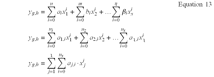
- where
- Y g,h is the estimated kinematic ({circumflex over (θ)}g,h) or kinetic ({circumflex over (m)}g,h) variables for the g lower extremities joint through the h plan of motion
- g is the lower extremities joint among the following set: hip, knee, ankle and metatarsophalangeal
- h is the plan of motion among the following set: sagittal, frontal and transversal
- x 1 is the jth locomotion related phenomenon, for example the jth localized plantar pressure
- a j,iis the ith coefficient associated the jth locomotion related phenomenon denoted xi
- n j is the order of the polynomial depicting the jth locomotion related phenomenon denoted x
- x is the number of locomotion related ph nomena
- If it is considered that the family of functions in Equation 13 are dependent on th state of the system they depict, thus following system of equations is obtained:

- where x is the time defendant state vector of the system
- In the preferred embodiment, x 1 may be substituted by the localized plantar pressures denoted fn
f , where if=[1, χ]. In the case of time-dependant equations, xi may be substituted by the time Thus, in the case of plantar pressures,Equation 14 becomes:
- where x is the time dependant state vector of the system
- Previously, y g,h has been defined as the estimated kinematic ({circumflex over (θ)}g,h) or kinetic ({circumflex over (m)}g,h) variable for the g lower extremities joints through the h plan of motion. Thus, Equation 15 may be written as:

- The goal is the identification of the
Equation 16 and Equation 17 functions from a set of nsamples, obtained from experimentation. A sample contains data related to the locomotion related phenomenon along with the corresponding Kinematic (θg,h) or kinetic (mg,h) variables. - The following array of data is obtained from experimentation:
TABLE 16 Data obtained from experimentation t x x1 x2 . . . xj . . . xχ θg,n mg,h 1 2 . . . . . . is . . . xj.l, . . . . . . . . . ns - where
- j, χ is the index and the number of locomotion related phenomena
- i s, ns is the index and the number of frames
- t is the time [s]
- x is the time dependant state vector of the system
- x j is the selected locomotion related phenomenon
- θ g,h is the Kinematic variables for the g lower extremities joint through the h plan of motion
- m g,h is the kinetic variable for the g lower extremities joint through the h plan of motion
- The logical functions a i,j (x) are then present d in th form of a look-up table, as shown in the following example;
TABLE 17 Look-up table example aj.l (x) t x a1.0 a1.1 . . . a2.0 a2.1 . . . aχ.0 aχ.1 . . . aχ.n λ 1 x1 34.5 23.1 . . . 12.3 92.5 . . . 83.6 52.4 . . . 72.5 2 x2 23.6 87.5 . . . 64.4 84.9 . . . 93.4 38.6 . . . 28.5 . . . . . . . . . . . . . . . . . . . . . . . . . . . . . . . . . ic xic 76.9 82.5 . . . 93.3 aj,t,i c . . . 37.5 82.3 . . . 84.4 . . . . . . . . . . . . . . . . . . . . . . . . . . . . . . . . . nc xnc 61.4 90.6 . . . 72.3 26.4 . . . 83.5 26.4 . . . 28.6 - where
- i c, nc index and dimension of the look-up table (nc is the number of considered quantized states)
- x is the time dependant state vector of the system
- Table 17 stablishes the relationship between the time dependent state vector of the system, the locomotion related phenomenon and the kinematic and the kinetic variables of the lower extremities joints, which are the following static characteristics:
- {circumflex over (θ)}g,h =f θ(x, x) Equation 18
- {circumflex over (m)} g,h =f m(x, x) Equation 19
- The methodology used to identify th parameters a(x) is based on th application of a curve-fitting algorithm to a set of data provided from experimentation on human subjects. This experimentation is p rformed in a laboratory environm nt under controlled conditions, yielding a s t of data in the form of an array, as shown in Table 16.
- The curve-fitting algorithm is used to obtain the parameters a j,i(x) for every given time dependant state vector x. This data is used to construct the look-up table, as shown in Table 17.
- An example of configuration for the method previously described is presented below:
- 1. the particularities of this configuration are:
- a. the locomotion related phenomenon is composed of a set of four localized plantar pressures supplied by the main artificial proprioceptors;
- b. the time dependant state vector is composed of:
- i. the walking speed of the subject;
- ii. the phase of locomotion portion and the portion of locomotion, and if
Equation 16 and Equation 17 are linear functions: - iii. the binary formatted magnitude of the four localized plantar pressures;
- 2. the family of functions depicting the static characteristics {circumflex over (θ)} g,h=fθ(x, x) and {circumflex over (m)}g,h=fm (x,.), as described in
Equation 16 and Equation 17; or - the family of functions depicting the time-dependant equations {circumflex over (θ)} g,h=fθ(X, t) and {circumflex over (m)}g,h=fm (x,t), as described in
Equation 16 and Equation 17 when fn1 is substituted by time t - 3. the selected lower extremities joints is the knee joint, which is the joint betwe n the thigh (th) and the shank (sh),
- 4. the selected plan of motion is the sagittal plan; In the case where
Equation 16 and Equation 17 are linear functions, th time dep ndant state vector further comprises the binary formatted magnitude of the four localized plantar pr ssures as added parameters to further segm nt the curv representing the kinematic (θg,h) or kinetic (mg,h) variables. This is due to the fact that, as shown by FIG. 20, that for a given portion of locomotion, phase of locomotion portion and subject's speed, the curve representing the kinematic (θg,h) or kin tic (mg,h) variables cannot efficiently be approximated by a linear function. To that end, the binary formatted plantar pressures are used to further subdivide the phase of locomotion portion in a number of intervals on which the curve representing the Kinematic (θg,h) or kinetic (mg,h) variables may be approximated by linear functions. FIG. 21 is a close-up view of FIG. 20 where it is shown that the curve representing the Kinematic (θg,h) or Kinetic (mg,h) variables appear relatively linear on each of the added subdivisions. Thus, the use ofEquation 16 and Equation 17 which are linear functions entails that the time dependant stated vector will further comprise the binary formatted plantar pressures. - It should be noted that in the preferred embodiment, the lookup table contains mathematical relationships that have been normalized in amplitude. The TG (44) uses the relative value of the localized plantar pressures instead of the magnitude of the signal. This means that the localized plantar pressures are set into a [0, 1] scal for a specific state of the whole system χ(k). This ensures that the mathematical relationships (time-dependant equations and static characteristics) are independent of the weight of the subject. It is worth to note that, because the TG's architecture use the walking speed as a component of the state of the whole system, the static characteristics lookup table is valid for any walking speed comprised % Within th operational conditions, which are, in the preferred embodiment, between 84 and 126 steps/min, though the lookup table may be computed for other intervals.
- The Regulator ( 48) uses a control law with a similar structure to control algorithms currently employed in numerous commercial or experimental applications. Various control laws may be implemented in the Regulator (48), examples of which are provided below.
- First, the Regulator ( 48) may us a simple PID control law, which is written as:

- where
- k d is the gain associated to the differential component of the regulator
- k p is the gain associated to the proportional component of the regulator
- k l is the gain associated to the integral component of the regulator
- x i is the requested trajectory
- x o is the trajectory performed by the system
- {overscore (x)} is the error between the requested (x l) and performed trajectory (xo)
- is the set point intended to the system
- applied to the proposed system, that is x=θ or x=m, we have:

- where
- g=[sagittal (sg), frontal (fr), transversal (tr)] is the plan of the motion
- h=[hip (hp), Knee (kn), ankle (an), metatarsophalangeal (mp)] is the joint
- x=θ or m
- where the transfer function between the error x and the set-point is expressed as:

- where
- b 2=kl+Kp+kd
- b 1=−(kp+kd)
- b 0=kd
- x=θ or m
- in which the corresponding recurrent equation is:
- μg,h x(k)=μg,h x(k−1)+b o ·{overscore (x)} g,h(k−2)+b 1 ·{overscore (x)} g,h(k−1)+b 2 ·{overscore (x)} g,h(k) Equation 23
- where
- k is the current increment
- x=θ or m
- Secondly, the Regulator ( 48) may use an adaptive PID control law. The transfer function of an adaptive PID is the same as that of a conventional PID but th parameters b2, b1 and b0 are function of the state of the whole system χ(k). From Equation 23, the recurrence equation of the adaptive PID is:
- μg,h x(k)=μg,h x(k−1)+b 0(χ(k))·{overscore (x)} g,h(k−2)+b 1 ·{overscore (x)} g,h(k−1)+b 2(χ(k))·{overscore (x)} g,h(k) Equation 23
- where
- k is the current increment
- x=θ or m
- Thirdly, the Regulator ( 48) may use a conventional PID with measured moment, which may be written as:
- f g,h μ(k)=f g,h m(k)+{overscore (f)} g,h(k)
Equation 25 - where
- f g,h m (k) is the force measured at the joint
- {overscore (f)} g,h(k) is the force generated by the regulator
- f g,h μ(k) is the set point of the force intended to the joint
-
Form Equation 22, the transfer function between the position error {overscore (x)}g,h and the force set-point {overscore (f)}g,h(k) is expressed as:
- where
- K is the gain yielded by the device between the position and the force set point
- x=θ or m
- Thus, the recurrent equation of the final force set point fg h (k) is given by the following relationship:
- f g,h μ(k)=f m(k)+{overscore (f)} g,h(k−1)+b 0 ·x g,h(k−2)+b1·{overscore (x)}g,h(k−1)+b2 ·{overscore (x)}g,h(k) Equati n 27
- where
- k is the current increment
- x=θ or m
Claims (81)
Priority Applications (4)
| Application Number | Priority Date | Filing Date | Title |
|---|---|---|---|
| US10/600,725 US7147667B2 (en) | 2002-08-22 | 2003-06-20 | Control system and method for controlling an actuated prosthesis |
| US11/270,684 US7867284B2 (en) | 2002-08-22 | 2005-11-09 | Control device and system for controlling an actuated prosthesis |
| US12/987,801 US20110137429A1 (en) | 2002-08-22 | 2011-01-10 | Control device and system for controlling an actuated prosthesis |
| US13/944,778 US9649206B2 (en) | 2002-08-22 | 2013-07-17 | Control device and system for controlling an actuated prosthesis |
Applications Claiming Priority (4)
| Application Number | Priority Date | Filing Date | Title |
|---|---|---|---|
| US40528102P | 2002-08-22 | 2002-08-22 | |
| US42426102P | 2002-11-06 | 2002-11-06 | |
| US45355603P | 2003-03-11 | 2003-03-11 | |
| US10/600,725 US7147667B2 (en) | 2002-08-22 | 2003-06-20 | Control system and method for controlling an actuated prosthesis |
Related Child Applications (1)
| Application Number | Title | Priority Date | Filing Date |
|---|---|---|---|
| US11/270,684 Division US7867284B2 (en) | 2002-08-22 | 2005-11-09 | Control device and system for controlling an actuated prosthesis |
Publications (2)
| Publication Number | Publication Date |
|---|---|
| US20040049290A1 true US20040049290A1 (en) | 2004-03-11 |
| US7147667B2 US7147667B2 (en) | 2006-12-12 |
Family
ID=31950541
Family Applications (7)
| Application Number | Title | Priority Date | Filing Date |
|---|---|---|---|
| US10/463,495 Expired - Lifetime US7314490B2 (en) | 2002-08-22 | 2003-06-17 | Actuated leg prosthesis for above-knee amputees |
| US10/600,725 Expired - Lifetime US7147667B2 (en) | 2002-08-22 | 2003-06-20 | Control system and method for controlling an actuated prosthesis |
| US11/270,684 Active 2027-06-22 US7867284B2 (en) | 2002-08-22 | 2005-11-09 | Control device and system for controlling an actuated prosthesis |
| US11/289,038 Active 2027-05-26 US8231687B2 (en) | 2002-08-22 | 2005-11-29 | Actuated leg prosthesis for above-knee amputees |
| US12/987,801 Abandoned US20110137429A1 (en) | 2002-08-22 | 2011-01-10 | Control device and system for controlling an actuated prosthesis |
| US13/540,342 Abandoned US20130035769A1 (en) | 2002-08-22 | 2012-07-02 | Actuated leg prosthesis for above-knee amputees |
| US13/944,778 Expired - Lifetime US9649206B2 (en) | 2002-08-22 | 2013-07-17 | Control device and system for controlling an actuated prosthesis |
Family Applications Before (1)
| Application Number | Title | Priority Date | Filing Date |
|---|---|---|---|
| US10/463,495 Expired - Lifetime US7314490B2 (en) | 2002-08-22 | 2003-06-17 | Actuated leg prosthesis for above-knee amputees |
Family Applications After (5)
| Application Number | Title | Priority Date | Filing Date |
|---|---|---|---|
| US11/270,684 Active 2027-06-22 US7867284B2 (en) | 2002-08-22 | 2005-11-09 | Control device and system for controlling an actuated prosthesis |
| US11/289,038 Active 2027-05-26 US8231687B2 (en) | 2002-08-22 | 2005-11-29 | Actuated leg prosthesis for above-knee amputees |
| US12/987,801 Abandoned US20110137429A1 (en) | 2002-08-22 | 2011-01-10 | Control device and system for controlling an actuated prosthesis |
| US13/540,342 Abandoned US20130035769A1 (en) | 2002-08-22 | 2012-07-02 | Actuated leg prosthesis for above-knee amputees |
| US13/944,778 Expired - Lifetime US9649206B2 (en) | 2002-08-22 | 2013-07-17 | Control device and system for controlling an actuated prosthesis |
Country Status (11)
| Country | Link |
|---|---|
| US (7) | US7314490B2 (en) |
| EP (3) | EP1531766B1 (en) |
| JP (3) | JP4808026B2 (en) |
| KR (2) | KR100690909B1 (en) |
| CN (2) | CN100506189C (en) |
| AT (1) | ATE416734T1 (en) |
| AU (2) | AU2003236750B2 (en) |
| CA (2) | CA2494364C (en) |
| DE (1) | DE60325221D1 (en) |
| ES (1) | ES2316771T3 (en) |
| WO (3) | WO2004017872A1 (en) |
Cited By (92)
| Publication number | Priority date | Publication date | Assignee | Title |
|---|---|---|---|---|
| US20020096537A1 (en) * | 1999-10-28 | 2002-07-25 | Ecolab Inc. | Data processing system for managing chemical product usage |
| US20040064195A1 (en) * | 2002-07-15 | 2004-04-01 | Hugh Herr | Variable-mechanical-impedance artificial legs |
| US20040078091A1 (en) * | 2002-10-15 | 2004-04-22 | Elkins Jeffrey L. | Foot-operated controller |
| WO2005079712A2 (en) | 2004-02-12 | 2005-09-01 | össur hf | System and method for motion-controlled foot unit |
| US20050283257A1 (en) * | 2004-03-10 | 2005-12-22 | Bisbee Charles R Iii | Control system and method for a prosthetic knee |
| US20060074493A1 (en) * | 2003-05-02 | 2006-04-06 | Bisbee Charles R Iii | Systems and methods of loading fluid in a prosthetic knee |
| WO2006024876A3 (en) * | 2004-09-02 | 2006-04-27 | Univ Surrey | A control system for a lower limb prosthesis or orthosis |
| US20060135883A1 (en) * | 2004-12-22 | 2006-06-22 | Jonsson Helgi | Systems and methods for processing limb motion |
| US20060136072A1 (en) * | 2004-05-07 | 2006-06-22 | Bisbee Charles R Iii | Magnetorheologically actuated prosthetic knee |
| US20060164038A1 (en) * | 2005-01-25 | 2006-07-27 | Remi Demers | Power supply charging method and device |
| US20060173552A1 (en) * | 2005-02-02 | 2006-08-03 | Roy Kim D | Prosthetic and orthotic systems usable for rehabilitation |
| US20060184280A1 (en) * | 2005-02-16 | 2006-08-17 | Magnus Oddsson | System and method of synchronizing mechatronic devices |
| US20060184252A1 (en) * | 2005-02-16 | 2006-08-17 | Magnus Oddsson | System and method for data communication with a mechatronic device |
| US20060195197A1 (en) * | 2005-02-02 | 2006-08-31 | Clausen Arinbjorn V | Sensing systems and methods for monitoring gait dynamics |
| US20060224246A1 (en) * | 2004-02-12 | 2006-10-05 | Clausen Arinbjorn V | Systems and methods for adjusting the angle of a prosthetic ankle based on a measured surface angle |
| US20070050045A1 (en) * | 2005-09-01 | 2007-03-01 | Clausen Arinbjorn V | Sensing system and method for motion-controlled foot unit |
| WO2007027808A3 (en) * | 2005-09-01 | 2007-06-28 | Oessur Hf | System and method for determining terrain transitions |
| US20070156252A1 (en) * | 2005-09-01 | 2007-07-05 | Ossur Hf | Actuator assebmly for prosthetic or orthotic joint |
| EP1955679A1 (en) | 2007-02-09 | 2008-08-13 | Semiconductor Energy Laboratory Co., Ltd. | Assist device |
| US20080277943A1 (en) * | 2005-08-10 | 2008-11-13 | Donelan James M | Method and apparatus for harvesting biomechanical energy |
| US20080288088A1 (en) * | 2007-02-06 | 2008-11-20 | Deka Products Limited Partnership | Arm prosthetic device |
| US7485152B2 (en) | 2005-08-26 | 2009-02-03 | The Ohio Willow Wood Company | Prosthetic leg having electronically controlled prosthetic knee with regenerative braking feature |
| US20090171469A1 (en) * | 2006-06-30 | 2009-07-02 | Freygardur Thorsteinsson | Intelligent orthosis |
| US20090271000A1 (en) * | 2007-02-06 | 2009-10-29 | Deka Products Limited Partnership | Dynamic support apparatus |
| EP2114316A2 (en) * | 2007-02-06 | 2009-11-11 | Deka Integrated Solutions Corp. | Method and apparatus for control of a prosthetic |
| US20090281462A1 (en) * | 2006-11-15 | 2009-11-12 | Commissariat A L' Energie Atomique | Device and method for following the movement of a living being |
| US20090299489A1 (en) * | 2005-04-19 | 2009-12-03 | Lisa Gramnaes | Combined Active and Passive Leg Prosthesis System and a Method for Performing a Movement With Such a System |
| US20100114329A1 (en) * | 2005-03-31 | 2010-05-06 | Iwalk, Inc. | Hybrid terrain-adaptive lower-extremity systems |
| US20100113980A1 (en) * | 2008-09-04 | 2010-05-06 | Iwalk, Inc. | Hybrid Terrain-Adaptive Lower-Extremity Systems |
| US20100185124A1 (en) * | 2004-03-10 | 2010-07-22 | Ossur Engineering, Inc. | Control system and method for a prosthetic knee |
| US20100241242A1 (en) * | 2005-03-31 | 2010-09-23 | Massachusetts Institute Of Technology | Artificial Joints Using Agonist-Antagonist Actuators |
| US20100268351A1 (en) * | 2007-02-06 | 2010-10-21 | Deka Products Limited Partnership | System, method and apparatus for control of a prosthetic device |
| WO2010120403A2 (en) * | 2009-04-13 | 2010-10-21 | Deka Products Limited Partnership | System, method and apparatus for control of a prosthetic device |
| WO2010120402A1 (en) * | 2009-04-13 | 2010-10-21 | Deka Products Limited Partnership | System and apparatus for orientation control |
| US20100274365A1 (en) * | 2007-02-06 | 2010-10-28 | Deka Products Limited Partnership | Arm prosthetic device |
| US20100324699A1 (en) * | 2005-03-31 | 2010-12-23 | Massachusetts Institute Of Technology | Model-Based Neuromechanical Controller for a Robotic Leg |
| WO2011022572A1 (en) * | 2009-08-20 | 2011-02-24 | Vanderbilt University | Control system for jointed mechanical devices |
| WO2011026086A1 (en) | 2009-08-31 | 2011-03-03 | Iwalk, Inc. | Implementing a stand-up sequence using a lower-extremity prosthesis or orthosis |
| US20110082566A1 (en) * | 2008-09-04 | 2011-04-07 | Herr Hugh M | Implementing a stand-up sequence using a lower-extremity prosthesis or orthosis |
| US8057550B2 (en) | 2004-02-12 | 2011-11-15 | össur hf. | Transfemoral prosthetic systems and methods for operating the same |
| US8074559B2 (en) | 2007-02-06 | 2011-12-13 | Deka Products Limited Partnership | Dynamic support apparatus and system |
| US20120226364A1 (en) * | 2009-11-13 | 2012-09-06 | Otto Bock Healthcare Products Gmbh | Method for controlling an orthotic or prosthetic joint of a lower extremity |
| US8287477B1 (en) | 2003-09-25 | 2012-10-16 | Massachusetts Institute Of Technology | Active ankle foot orthosis |
| US20130173019A1 (en) * | 2006-03-24 | 2013-07-04 | Blatchford Products Limited | Lower Limb Prosthesis and Control Unit |
| US8500823B2 (en) | 2005-03-31 | 2013-08-06 | Massachusetts Institute Of Technology | Powered artificial knee with agonist-antagonist actuation |
| US8512415B2 (en) | 2005-03-31 | 2013-08-20 | Massachusetts Institute Of Technology | Powered ankle-foot prothesis |
| US8736087B2 (en) | 2011-09-01 | 2014-05-27 | Bionic Power Inc. | Methods and apparatus for control of biomechanical energy harvesting |
| US8734528B2 (en) | 2005-03-31 | 2014-05-27 | Massachusetts Institute Of Technology | Artificial ankle-foot system with spring, variable-damping, and series-elastic actuator components |
| US8828093B1 (en) * | 2008-04-15 | 2014-09-09 | Rehabilitation Institute Of Chicago | Identification and implementation of locomotion modes using surface electromyography |
| US8979943B2 (en) | 2007-02-06 | 2015-03-17 | Deka Products Limited Partnership | Arm prosthetic device |
| US9017419B1 (en) | 2012-03-09 | 2015-04-28 | össur hf | Linear actuator |
| US20150120044A1 (en) * | 2013-10-31 | 2015-04-30 | Disney Enterprises, Inc. | Method for gait generation and tracking control for a bipedal walking robot |
| US9032635B2 (en) | 2011-12-15 | 2015-05-19 | Massachusetts Institute Of Technology | Physiological measurement device or wearable device interface simulator and method of use |
| US9060883B2 (en) | 2011-03-11 | 2015-06-23 | Iwalk, Inc. | Biomimetic joint actuators |
| US9114030B2 (en) | 2007-02-06 | 2015-08-25 | Deka Products Limited Partnership | System for control of a prosthetic device |
| US9221177B2 (en) | 2012-04-18 | 2015-12-29 | Massachusetts Institute Of Technology | Neuromuscular model-based sensing and control paradigm for a robotic leg |
| US9265625B2 (en) | 2009-08-20 | 2016-02-23 | Vanderbilt University | Jointed mechanical devices |
| US20160058582A1 (en) * | 2014-08-28 | 2016-03-03 | Rehabilitation Institute Of Chicago | Minimum Jerk Swing Control for Assistive Device |
| US9333097B2 (en) | 2005-03-31 | 2016-05-10 | Massachusetts Institute Of Technology | Artificial human limbs and joints employing actuators, springs, and variable-damper elements |
| US20160158029A1 (en) * | 2014-12-08 | 2016-06-09 | Rehabilitation Institute Of Chicago | Powered and passive assistive device and related methods |
| US20160242936A1 (en) * | 2008-04-21 | 2016-08-25 | Vanderbilt University | Powered leg prosthesis and control methodologies for obtaining near normal gait |
| US20160346100A1 (en) * | 2015-05-29 | 2016-12-01 | Ossur Iceland Ehf | Pump system for use with a prosthetic device |
| US9687377B2 (en) | 2011-01-21 | 2017-06-27 | Bionx Medical Technologies, Inc. | Terrain adaptive powered joint orthosis |
| US9693883B2 (en) | 2010-04-05 | 2017-07-04 | Bionx Medical Technologies, Inc. | Controlling power in a prosthesis or orthosis based on predicted walking speed or surrogate for same |
| US9737419B2 (en) | 2011-11-02 | 2017-08-22 | Bionx Medical Technologies, Inc. | Biomimetic transfemoral prosthesis |
| DE102016107615B3 (en) * | 2016-04-25 | 2017-10-12 | Cavos Bagatelle Verwaltungs Gmbh & Co. Kg | prosthesis |
| US9839552B2 (en) | 2011-01-10 | 2017-12-12 | Bionx Medical Technologies, Inc. | Powered joint orthosis |
| US9844447B2 (en) | 2010-04-09 | 2017-12-19 | Deka Products Limited Partnership | System and apparatus for robotic device and methods of using thereof |
| US9943421B2 (en) | 2015-05-21 | 2018-04-17 | Ossur Iceland Ehf | Membrane pump system for use with a prosthetic system |
| US10016290B2 (en) | 2012-09-17 | 2018-07-10 | Vanderbilt University | Walking controller for powered ankle prostheses |
| US10143581B2 (en) | 2013-06-21 | 2018-12-04 | Ossur Hf | Dynamic tension system for orthopedic device |
| US10195099B2 (en) | 2016-01-11 | 2019-02-05 | Bionic Power Inc. | Method and system for intermittently assisting body motion |
| US10307272B2 (en) | 2005-03-31 | 2019-06-04 | Massachusetts Institute Of Technology | Method for using a model-based controller for a robotic leg |
| US10369018B2 (en) | 2012-04-30 | 2019-08-06 | Ossur Hf | Prosthetic device, system and method for increasing vacuum attachment |
| US10413437B2 (en) | 2013-01-25 | 2019-09-17 | Ossur Iceland Ehf | Orthopedic device having a dynamic control system and method for using the same |
| US10413429B2 (en) | 2015-08-27 | 2019-09-17 | Ossur Iceland Ehf | Pump system |
| US10485681B2 (en) | 2005-03-31 | 2019-11-26 | Massachusetts Institute Of Technology | Exoskeletons for running and walking |
| US10512554B2 (en) | 2016-08-26 | 2019-12-24 | Ossur Iceland Ehf | Pump system |
| US10531965B2 (en) | 2012-06-12 | 2020-01-14 | Bionx Medical Technologies, Inc. | Prosthetic, orthotic or exoskeleton device |
| US10537449B2 (en) | 2011-01-12 | 2020-01-21 | Bionx Medical Technologies, Inc. | Controlling powered human augmentation devices |
| US10610384B2 (en) | 2015-03-04 | 2020-04-07 | Freedom Innovations, Llc | Lower limb prosthesis |
| US10617537B2 (en) | 2012-02-14 | 2020-04-14 | Ossur Hf | Vacuum assisted suspension system |
| US10653546B2 (en) | 2014-10-31 | 2020-05-19 | Ossur Hf | Orthopedic device having a dynamic control system |
| US10695198B2 (en) | 2015-01-08 | 2020-06-30 | Ossur Iceland Ehf | Pump mechanism |
| US10729568B2 (en) | 2014-07-01 | 2020-08-04 | Ossur Hf | Pump mechanism for vacuum suspension system |
| WO2021005006A2 (en) | 2019-07-08 | 2021-01-14 | Georg-August-Universität Göttingen Stiftung Öffentlichen Rechts, Universitätsmedizin | Methods and systems for controlling active prostheses |
| US10898363B2 (en) | 2011-10-31 | 2021-01-26 | Ossur Hf | Orthopedic device for dynamically treating the knee |
| US11014251B2 (en) | 2016-11-24 | 2021-05-25 | Kawasaki Jukogyo Kabushiki Kaisha | Joint structure for robot |
| US11278433B2 (en) | 2005-03-31 | 2022-03-22 | Massachusetts Institute Of Technology | Powered ankle-foot prosthesis |
| US11464655B2 (en) | 2007-02-06 | 2022-10-11 | Deka Products Limited Partnership | Arm prosthetic device |
| US11547590B2 (en) | 2017-11-27 | 2023-01-10 | Ossur Iceland Ehf | Orthopedic device having a suspension element |
| US11779476B2 (en) | 2007-02-06 | 2023-10-10 | Deka Products Limited Partnership | Arm prosthetic device |
Families Citing this family (96)
| Publication number | Priority date | Publication date | Assignee | Title |
|---|---|---|---|---|
| US20090030530A1 (en) * | 2002-04-12 | 2009-01-29 | Martin James J | Electronically controlled prosthetic system |
| EP1539028A2 (en) * | 2002-07-08 | 2005-06-15 | Ossur Engineering Inc. | Socket liner incorporating sensors to monitor amputee progress |
| KR100690909B1 (en) * | 2002-08-22 | 2007-03-09 | 빅톰 휴먼 바이오닉스 인크. | Actuated Leg Prosthesis for Above-knee Amputees |
| US7736394B2 (en) * | 2002-08-22 | 2010-06-15 | Victhom Human Bionics Inc. | Actuated prosthesis for amputees |
| WO2005048887A1 (en) * | 2003-11-18 | 2005-06-02 | Victhom Human Bionics Inc. | Instrumented prosthetic foot |
| US7815689B2 (en) | 2003-11-18 | 2010-10-19 | Victhom Human Bionics Inc. | Instrumented prosthetic foot |
| US20050107889A1 (en) * | 2003-11-18 | 2005-05-19 | Stephane Bedard | Instrumented prosthetic foot |
| DE102005021412A1 (en) * | 2005-05-04 | 2006-11-09 | Otto Bock Healthcare Products Gmbh | System of a liner with a myoelectric electrode unit |
| US7717962B2 (en) * | 2006-03-22 | 2010-05-18 | Wilson Michael T | Proprioception enhancement device |
| WO2008080234A1 (en) * | 2007-01-05 | 2008-07-10 | Victhom Human Bionics Inc. | Joint actuation mechanism for a prosthetic and/or orthotic device having a compliant transmission |
| CA2673915C (en) * | 2007-01-05 | 2016-06-28 | Victhom Human Bionics, Inc. | High torque active mechanism for orthotic and/or prosthetic devices |
| CA2676067C (en) * | 2007-01-19 | 2017-06-20 | Victhom Human Bionics, Inc. | Reactive layer control system for prosthetic and orthotic devices |
| US8652218B2 (en) * | 2008-04-21 | 2014-02-18 | Vanderbilt University | Powered leg prosthesis and control methodologies for obtaining near normal gait |
| US8231688B2 (en) * | 2008-06-16 | 2012-07-31 | Berkeley Bionics | Semi-actuated transfemoral prosthetic knee |
| US9351855B2 (en) | 2008-06-16 | 2016-05-31 | Ekso Bionics, Inc. | Powered lower extremity orthotic and method of operation |
| US8731716B2 (en) | 2008-08-28 | 2014-05-20 | Raytheon Company | Control logic for biomimetic joint actuators |
| US20110213599A1 (en) * | 2008-08-28 | 2011-09-01 | Raytheon Company | Method of Sizing Actuators for a Biomimetic Mechanical Joint |
| CN102196785B (en) * | 2008-08-28 | 2014-02-26 | 雷神公司 | A biomimetic mechanical joint |
| DE102008045113B4 (en) | 2008-09-01 | 2011-08-25 | Otto Bock HealthCare GmbH, 37115 | Prosthetic knee joint and method for operating a prosthetic knee joint |
| US20100191100A1 (en) * | 2009-01-23 | 2010-07-29 | Warsaw Orthopedic, Inc. | Methods and systems for diagnosing, treating, or tracking spinal disorders |
| US8126736B2 (en) | 2009-01-23 | 2012-02-28 | Warsaw Orthopedic, Inc. | Methods and systems for diagnosing, treating, or tracking spinal disorders |
| US8685093B2 (en) | 2009-01-23 | 2014-04-01 | Warsaw Orthopedic, Inc. | Methods and systems for diagnosing, treating, or tracking spinal disorders |
| CN101496751B (en) * | 2009-03-11 | 2011-08-10 | 河北工业大学 | Active mode human leg prosthetic limb |
| US9017418B2 (en) * | 2009-05-05 | 2015-04-28 | össur hf | Control systems and methods for prosthetic or orthotic devices |
| US9387096B2 (en) * | 2009-06-17 | 2016-07-12 | Ossur Hf | Feedback control systems and methods for prosthetic or orthotic devices |
| DE102009030995A1 (en) | 2009-06-30 | 2011-01-05 | Fraunhofer-Gesellschaft zur Förderung der angewandten Forschung e.V. | Active prosthetic device with terrain detection and method for controlling an active prosthetic device |
| DE102009052894A1 (en) | 2009-11-13 | 2011-06-01 | Otto Bock Healthcare Products Gmbh | Method and device for controlling an artificial orthotic or prosthetic joint |
| DE102009052895A1 (en) | 2009-11-13 | 2011-05-19 | Otto Bock Healthcare Products Gmbh | Method and device for controlling an artificial orthotic or prosthetic knee joint |
| US8623098B2 (en) * | 2010-07-01 | 2014-01-07 | Vanderbilt University | Systems and method for volitional control of jointed mechanical devices based on surface electromyography |
| CA2804392C (en) | 2010-07-07 | 2018-08-07 | Ossur Hf | Ground contact sensing systems and methods for lower-limb orthotic and prosthetic devices |
| EP2621414B1 (en) | 2010-09-29 | 2019-03-13 | Össur HF | Prosthetic and orthotic devices and methods and systems for controlling the same |
| EP2672931A1 (en) | 2011-02-10 | 2013-12-18 | Université de Mons | Method for determining an artificial periodic patterned signal |
| WO2012119156A2 (en) * | 2011-03-03 | 2012-09-07 | D-Rev: Design For The Other Ninety Percent | Polycentric knee joint prosthesis for extreme affordability |
| US9060884B2 (en) | 2011-05-03 | 2015-06-23 | Victhom Human Bionics Inc. | Impedance simulating motion controller for orthotic and prosthetic applications |
| USD733883S1 (en) | 2011-05-31 | 2015-07-07 | Ossur Hf | Prosthetic knee |
| WO2012166853A1 (en) | 2011-05-31 | 2012-12-06 | Ossur Hf | Prosthetic knee |
| US10543109B2 (en) | 2011-11-11 | 2020-01-28 | Össur Iceland Ehf | Prosthetic device and method with compliant linking member and actuating linking member |
| US9532877B2 (en) | 2011-11-11 | 2017-01-03 | Springactive, Inc. | Robotic device and method of using a parallel mechanism |
| CN102641196B (en) * | 2011-12-30 | 2013-12-11 | 中国科学院深圳先进技术研究院 | Rehealthy training robot control system and control method thereof |
| US10307271B2 (en) * | 2012-02-17 | 2019-06-04 | Össur Iceland Ehf | Control system and method for non-gait ankle and foot motion in human assistance device |
| US9622884B2 (en) * | 2012-02-17 | 2017-04-18 | Springactive, Inc. | Control systems and methods for gait devices |
| US9044346B2 (en) | 2012-03-29 | 2015-06-02 | össur hf | Powered prosthetic hip joint |
| US9149371B2 (en) | 2012-04-05 | 2015-10-06 | Ossur Hf | Prosthetic knee |
| EP2854717B1 (en) * | 2012-05-24 | 2020-12-30 | Ekso Bionics, Inc. | Powered lower extremity orthotic |
| DE102012013141A1 (en) | 2012-07-03 | 2014-05-08 | Otto Bock Healthcare Gmbh | Orthotic or prosthetic joint device and method for its control |
| US9259343B2 (en) | 2012-07-06 | 2016-02-16 | Newman Technologies LLC | Device for mitigating plantar fasciitis |
| EP2877130B1 (en) | 2012-07-27 | 2017-02-22 | Proteor | Hydraulic system for a knee-ankle assembly controlled by a microprocessor |
| DE102012107117A1 (en) | 2012-08-02 | 2014-02-06 | Georg-August-Universität Göttingen Stiftung Öffentlichen Rechts | Orthesensteuerung |
| EP2702963A1 (en) | 2012-08-27 | 2014-03-05 | ETH Zürich | Powered prosthesis with serial and/or parallel compliance |
| CN102783766B (en) * | 2012-08-28 | 2014-11-19 | 中国科学院深圳先进技术研究院 | Fall prevention device |
| JP5709237B2 (en) | 2012-08-30 | 2015-04-30 | ナブテスコ株式会社 | Sealed prosthetic leg |
| US9351900B2 (en) | 2012-09-17 | 2016-05-31 | President And Fellows Of Harvard College | Soft exosuit for assistance with human motion |
| KR101401435B1 (en) * | 2012-10-16 | 2014-05-30 | 인하대학교 산학협력단 | Artificial leg |
| WO2014089331A1 (en) | 2012-12-06 | 2014-06-12 | Ossur Hf | Electrical stimulation for orthopedic devices |
| EP2961355B1 (en) | 2013-02-26 | 2018-08-22 | Össur hf | Prosthetic foot with enhanced stability and elastic energy return |
| WO2014159114A1 (en) | 2013-03-14 | 2014-10-02 | össur hf | Prosthetic ankle: a method of controlling based on adaptation to speed |
| US10314723B2 (en) * | 2013-05-23 | 2019-06-11 | Rehabilitation Institute Of Chicago | Effective shape controller for lower limb |
| KR20160016925A (en) | 2013-05-31 | 2016-02-15 | 프레지던트 앤드 펠로우즈 오브 하바드 칼리지 | Soft exosuit for assistance with human motion |
| CN104224411B (en) * | 2013-06-24 | 2017-03-22 | 苏州大学 | Method for providing affected limb side knee joint reference motions in real time |
| CA2866028A1 (en) | 2013-10-03 | 2015-04-03 | Farsad Kiani | Electrical stimulation for a functional electrical stimulation system |
| US9375569B2 (en) | 2013-10-03 | 2016-06-28 | Ensilver Canada | Controller unit for a functional electrical stimulation (FES) orthotic system |
| CA2866025A1 (en) | 2013-10-03 | 2015-04-03 | Quiang Song | Sensor unit for a functional electrical stimulation (fes) orthotic system |
| KR102146363B1 (en) * | 2013-10-31 | 2020-08-20 | 삼성전자주식회사 | Wearable robot and control method for the same |
| AU2014364219A1 (en) | 2013-12-09 | 2016-06-30 | President And Fellows Of Harvard College | Assistive flexible suits, flexible suit systems, and methods for making and control thereof to assist human mobility |
| US10278883B2 (en) | 2014-02-05 | 2019-05-07 | President And Fellows Of Harvard College | Systems, methods, and devices for assisting walking for developmentally-delayed toddlers |
| WO2015126849A1 (en) | 2014-02-18 | 2015-08-27 | össur hf | Prosthetic joint with cam locking mechanism |
| US10864100B2 (en) | 2014-04-10 | 2020-12-15 | President And Fellows Of Harvard College | Orthopedic device including protruding members |
| CN106456339B (en) | 2014-04-11 | 2020-02-07 | 奥索有限责任公司 | Prosthetic foot with removable flexible member |
| US10434030B2 (en) | 2014-09-19 | 2019-10-08 | President And Fellows Of Harvard College | Soft exosuit for assistance with human motion |
| KR102342072B1 (en) * | 2014-10-14 | 2021-12-22 | 삼성전자주식회사 | Method and apparatus for conrolling walking assist |
| US9364657B2 (en) | 2014-10-31 | 2016-06-14 | Ensilver Canada | Cuff unit for a functional electrical stimulation system |
| EP3285694B1 (en) | 2015-04-20 | 2021-03-10 | Ossur Iceland EHF | Electromyography with prosthetic or orthotic devices |
| US20170067548A1 (en) * | 2015-08-17 | 2017-03-09 | Peter Neuhaus | Linkage Actuator |
| US9949850B2 (en) | 2015-09-18 | 2018-04-24 | Össur Iceland Ehf | Magnetic locking mechanism for prosthetic or orthotic joints |
| US10806657B2 (en) * | 2015-09-23 | 2020-10-20 | Universitè Catholique De Louvain | Rehabilitation system and method |
| EP3380048B8 (en) | 2015-11-24 | 2021-08-25 | University of South Carolina | Dynamic linear adjustable prosthetic |
| CN109069278A (en) | 2016-03-13 | 2018-12-21 | 哈佛大学校长及研究员协会 | Flexible member for being anchored on body |
| KR101836636B1 (en) | 2016-05-19 | 2018-03-09 | 현대자동차주식회사 | Wearable walking assistant robot and method for controlling the same |
| US11498203B2 (en) | 2016-07-22 | 2022-11-15 | President And Fellows Of Harvard College | Controls optimization for wearable systems |
| CN107795653B (en) | 2016-08-30 | 2020-03-17 | 上银科技股份有限公司 | Linear drive system for installation in a prosthetic limb |
| KR101859063B1 (en) | 2016-09-22 | 2018-05-17 | 하이윈 테크놀로지스 코포레이션 | In-prosthesis linear drive system |
| CN114209479A (en) * | 2016-11-10 | 2022-03-22 | 国立大学法人东京大学 | Knee joint |
| JP6793203B2 (en) | 2016-11-18 | 2020-12-02 | Cyberdyne株式会社 | Artificial limb movement assisting device and artificial limb movement assisting method |
| US10253855B2 (en) | 2016-12-15 | 2019-04-09 | Boston Dynamics, Inc. | Screw actuator for a legged robot |
| WO2018170170A1 (en) | 2017-03-14 | 2018-09-20 | President And Fellows Of Harvard College | Systems and methods for fabricating 3d soft microstructures |
| CN106974750A (en) * | 2017-05-03 | 2017-07-25 | 哈尔滨理工大学 | A kind of power type knee joint artificial limb |
| JP7399846B2 (en) | 2017-08-21 | 2023-12-18 | セルジーン コーポレイション | Preparation process of (S)-TERT-butyl 4,5-diamino-5-oxopentanoate |
| CN107456300A (en) * | 2017-09-21 | 2017-12-12 | 哈尔滨工业大学 | The quick myoelectricity code control system of multiple freedom degrees hand-prosthesis based on FSM |
| CN107618018B (en) * | 2017-10-26 | 2020-08-25 | 杭州电子科技大学 | Manipulator action speed proportional control method based on myoelectricity |
| KR20190102485A (en) | 2018-02-26 | 2019-09-04 | 한국기계연구원 | Method of controlling robotic artificial leg and apparatus for controlling robotic artificial leg |
| KR102207703B1 (en) | 2019-02-07 | 2021-01-26 | 한국기계연구원 | Robot artificial leg and method of operating robot artificial leg |
| KR102073621B1 (en) | 2019-02-28 | 2020-02-06 | 한국기계연구원 | Integrated drive apparatus and knee-type robot artificial leg |
| CN110394801B (en) * | 2019-08-06 | 2021-04-16 | 前元运立(北京)机器人智能科技有限公司 | Joint control system of robot |
| KR102328754B1 (en) | 2020-03-20 | 2021-11-18 | 한국기계연구원 | Knee-type robot artificial leg and method of controlling the same |
| KR102267250B1 (en) * | 2020-09-09 | 2021-06-22 | 근로복지공단 | Verification system for walking algorithm |
| KR102419344B1 (en) | 2020-09-14 | 2022-07-11 | 한국기계연구원 | Robot artificial leg and method of operating robot artificial leg |
Citations (20)
| Publication number | Priority date | Publication date | Assignee | Title |
|---|---|---|---|---|
| US52663A (en) * | 1866-02-20 | Improvement in sleds | ||
| US229400A (en) * | 1880-06-29 | Car-coupling | ||
| US544528A (en) * | 1895-08-13 | Button-attaching machine | ||
| US4030141A (en) * | 1976-02-09 | 1977-06-21 | The United States Of America As Represented By The Veterans Administration | Multi-function control system for an artificial upper-extremity prosthesis for above-elbow amputees |
| US4521924A (en) * | 1983-03-01 | 1985-06-11 | University Of Utah | Electrically driven artificial arm |
| US5062856A (en) * | 1988-03-25 | 1991-11-05 | Kabushiki Kaisha Kobe Seiko Sho | Teaching playback swing-phase-controlled above-knee prosthesis |
| US5252102A (en) * | 1989-01-24 | 1993-10-12 | Electrobionics Corporation | Electronic range of motion apparatus, for orthosis, prosthesis, and CPM machine |
| US5383939A (en) * | 1991-12-05 | 1995-01-24 | James; Kelvin B. | System for controlling artificial knee joint action in an above knee prosthesis |
| US5571213A (en) * | 1992-11-17 | 1996-11-05 | Allen; Scott | Prosthetic foot |
| US5650704A (en) * | 1995-06-29 | 1997-07-22 | Massachusetts Institute Of Technology | Elastic actuator for precise force control |
| US5704946A (en) * | 1996-03-13 | 1998-01-06 | United States Manufacturing Company | Multi-purpose prosthetic knee component |
| US5779735A (en) * | 1996-05-17 | 1998-07-14 | Molino; Joseph L. | Knee unit for above-knee prosthetic leg |
| US5888213A (en) * | 1997-06-06 | 1999-03-30 | Motion Control, Inc. | Method and apparatus for controlling an externally powered prosthesis |
| US5888212A (en) * | 1997-06-26 | 1999-03-30 | Mauch, Inc. | Computer controlled hydraulic resistance device for a prosthesis and other apparatus |
| US5888246A (en) * | 1994-03-12 | 1999-03-30 | Royal Infirmary Of Edinburgh Nhs Trust | Motor drive system and linkage for hand prosthesis |
| US5893891A (en) * | 1993-06-11 | 1999-04-13 | Chas. A. Blatchford & Sons Limited | Prosthesis control system |
| US6007582A (en) * | 1996-03-29 | 1999-12-28 | Ortho Europe Limited | Prosthetic foot with means for energy storage and release |
| US6113642A (en) * | 1996-06-27 | 2000-09-05 | Mauch, Inc. | Computer controlled hydraulic resistance device for a prosthesis and other apparatus |
| US6361570B1 (en) * | 1997-10-24 | 2002-03-26 | Lothian Primary Care Nhs Trust | Upper limb prosthesis |
| US6494039B2 (en) * | 2000-03-01 | 2002-12-17 | Massachusetts Institute Of Technology | Force-controlled hydro-elastic actuator |
Family Cites Families (413)
| Publication number | Priority date | Publication date | Assignee | Title |
|---|---|---|---|---|
| US909859A (en) | 1909-01-19 | John T Apgar | Artificial leg. | |
| US577935A (en) * | 1897-03-02 | Horse-detacher | ||
| US2619652A (en) | 1947-09-18 | 1952-12-02 | A J Hosmer Corp | Artificial limb |
| US2568051A (en) | 1947-10-10 | 1951-09-18 | John G Catranis | Artificial leg |
| US2475373A (en) | 1947-12-11 | 1949-07-05 | John G Catranis | Three-part artificial foot(lateral motion and ankle rotation) |
| US2859451A (en) | 1956-11-05 | 1958-11-11 | Hans A Mauch | Hydraulic system |
| US3316558A (en) * | 1963-11-12 | 1967-05-02 | La Vaughn L Mortensen | Prosthetic leg with a hydraulic knee control |
| DE1491236A1 (en) | 1965-09-28 | 1969-05-22 | Teufel Wilh Jul Fa | Artificial knee joint for prosthetic legs |
| NL6612233A (en) * | 1966-08-30 | 1968-03-01 | ||
| AT297918B (en) * | 1969-05-03 | 1972-04-10 | Bock Orthopaed Ind | Adjustable connecting element for prosthesis parts |
| US3589134A (en) | 1969-10-30 | 1971-06-29 | Westinghouse Electric Corp | Manipulator apparatus |
| US3820168A (en) | 1970-05-01 | 1974-06-28 | Bock O Orthopaedische Ind Fa K | System for operating a prosthetic limb |
| US3701368A (en) | 1971-06-23 | 1972-10-31 | Rca Corp | Fabrication of liquid crystal devices |
| CH543277A (en) * | 1971-09-27 | 1973-10-31 | Battelle Memorial Institute | Replacement prosthesis for part of a lower limb |
| US3791375A (en) * | 1971-09-29 | 1974-02-12 | E Pfeiffer | Device for sensing and warning of excessive ambulation force |
| US3866246A (en) * | 1972-11-14 | 1975-02-18 | Us Navy | Shoulder disarticulation prosthetic system |
| GB1454913A (en) | 1974-02-26 | 1976-11-10 | Blatchford & Sons Ltd | Artificial limbs |
| AT334521B (en) * | 1974-03-08 | 1976-01-25 | Forsch Orthopadie Technik | ANKLE |
| US4005496A (en) * | 1974-06-28 | 1977-02-01 | Hosmer/Dorrance Corporation | Prosthetic knee joint |
| FR2293185A1 (en) * | 1974-12-02 | 1976-07-02 | Bernard Jean | Artificial leg with actuator - has unit on good leg moved by body weight coupled by flexible guide to receiver |
| US3995324A (en) | 1975-09-12 | 1976-12-07 | The United States Of America As Represented By The Administrator Of The National Aeronautics And Space Administration | Actuator device for artificial leg |
| FR2002163A1 (en) * | 1976-01-22 | 1969-10-17 | Siemens Ag | |
| US4023215A (en) * | 1976-02-17 | 1977-05-17 | Moore Robert R | Locking prosthetic knee |
| US4064569A (en) | 1976-09-23 | 1977-12-27 | Campbell Harry E | Artificial polycentric knee joint |
| US4065815A (en) * | 1976-09-28 | 1978-01-03 | Sen Jung Chen | Hydraulically controlled artificial leg |
| US4100918A (en) | 1977-03-25 | 1978-07-18 | Indiana University Foundation | Dynamic orthotic knee extension assist device |
| US4209860A (en) | 1978-02-13 | 1980-07-01 | The United States of America as represented by the Administrator of Veterans' Affairs | System and method for multifunctional control of upper limb prosthesis via EMg signal identification |
| US4179759A (en) * | 1978-02-16 | 1979-12-25 | Smith James A | Artificial leg having a lockable knee joint |
| DE2841999C2 (en) * | 1978-09-27 | 1981-11-26 | Otto Bock, Orthopädische Industrie KG, 3428 Duderstadt | Artificial knee joint |
| US4354676A (en) | 1978-10-13 | 1982-10-19 | Pepsico, Inc. | Exerciser |
| US4212087A (en) | 1978-11-16 | 1980-07-15 | Mortensen Lavaugh L | Prosthetic leg with a hydraulic control |
| JPS55113438A (en) * | 1979-02-26 | 1980-09-02 | Kogyo Gijutsuin | Device for discriminating pattern of muscular potential |
| US4387472A (en) | 1980-10-02 | 1983-06-14 | Medical Center Prosthetics, Inc. | Torque absorber with biofeedback |
| US4386891A (en) | 1981-04-23 | 1983-06-07 | General Motors Corporation | Rotary hydraulic vane pump with undervane passages for priming |
| US4433679A (en) * | 1981-05-04 | 1984-02-28 | Mauldin Donald M | Knee and elbow brace |
| DE3269147D1 (en) | 1981-06-09 | 1986-03-27 | Hanger & Co Ltd J E | Knee joint for artificial legs |
| US4657000A (en) * | 1981-07-23 | 1987-04-14 | Dynasplints Systems, Inc. | Adjustable splint and securing means therefor |
| US4518307A (en) * | 1982-09-29 | 1985-05-21 | The Boeing Company | Compliant robot arm adapter assembly |
| JPS59189843A (en) | 1983-04-11 | 1984-10-27 | 工業技術院長 | Foot neck operating mechanism in power artificial leg |
| US4569352A (en) * | 1983-05-13 | 1986-02-11 | Wright State University | Feedback control system for walking |
| US4578083A (en) * | 1983-05-16 | 1986-03-25 | Williams Allton C | Artificial leg |
| US4556956A (en) | 1983-09-16 | 1985-12-03 | General Electric Company | Adjustable gain controller for valve position control loop and method for reducing jitter |
| JPS6081530A (en) | 1983-10-12 | 1985-05-09 | Nec Corp | Viscous damper |
| CA1276710C (en) | 1983-11-30 | 1990-11-20 | Kazuo Asakawa | Robot force controlling system |
| US4558704A (en) * | 1983-12-15 | 1985-12-17 | Wright State University | Hand control system |
| US4579558A (en) | 1984-01-10 | 1986-04-01 | Ramer James L | Mechanical hip joint |
| FR2559394B1 (en) * | 1984-02-10 | 1986-07-11 | Carsalade Charles | APPARATUS TO FACILITATE THE PRACTICE OF ALPINE SKIING IN PARTICULAR |
| US4600357A (en) | 1984-02-21 | 1986-07-15 | Heath Company | Gripper force sensor/controller for robotic arm |
| JPS60177102A (en) | 1984-02-24 | 1985-09-11 | Mazda Motor Corp | Method for impregnating lead to ferrous sintered alloy |
| US4602619A (en) | 1984-10-02 | 1986-07-29 | Wolf Susan G | Method and device for producing variable spinal traction |
| US4657470A (en) * | 1984-11-15 | 1987-04-14 | Westinghouse Electric Corp. | Robotic end effector |
| SU1447366A1 (en) * | 1985-03-04 | 1988-12-30 | Украинский Научно-Исследовательский Институт Протезирования, Протезостроения, Экспертизы И Восстановления Трудоспособности Инвалидов | Apparatus for controlling prostheses of the lower extermities |
| DE3519046A1 (en) | 1985-05-28 | 1986-12-04 | Otto Bock Orthopädische Industrie Besitz- und Verwaltungs-Kommanditgesellschaft, 3408 Duderstadt | BRAKE KNEE JOINT |
| DE8515598U1 (en) | 1985-05-28 | 1985-07-11 | Otto Bock Orthopädische Industrie Besitz- und Verwaltungs-Kommanditgesellschaft, 3408 Duderstadt | Lockable knee joint |
| US4649934A (en) * | 1985-06-07 | 1987-03-17 | Faro Medical Technologies, Inc. | Joint laxity measurement |
| GB2177603B (en) | 1985-07-09 | 1989-07-19 | David Ernest Young | Modular lower limb bracing system |
| AT391076B (en) * | 1985-11-06 | 1990-08-10 | Bock Orthopaed Ind | SWIVEL JOINT |
| DE3543291A1 (en) | 1985-12-07 | 1987-06-11 | Bosch Gmbh Robert | Hydraulic shock absorber (damper) |
| CA1260986A (en) | 1985-12-11 | 1989-09-26 | Frank R. Bubic | Artificial musculoskeletal mechanism |
| US4711242A (en) | 1986-02-18 | 1987-12-08 | Wright State University | Control system for knee joint |
| US4652266A (en) | 1986-03-07 | 1987-03-24 | Kingsley Mfg. Co. | Molded elastomeric prosthetic foot having energy-storing articulated keel |
| US4760850A (en) | 1986-05-15 | 1988-08-02 | Wright State University | Method for balancing assistance |
| US4814661A (en) * | 1986-05-23 | 1989-03-21 | Washington State University Research Foundation, Inc. | Systems for measurement and analysis of forces exerted during human locomotion |
| US4805455A (en) * | 1987-04-24 | 1989-02-21 | Myo-Tech Corp. | Muscle testing apparatus and method |
| FR2599246B1 (en) | 1986-06-02 | 1991-10-25 | Paris Administ Gle Assistance | DYNAMIC ORTHESIS OF THE KNEE. |
| GB8625144D0 (en) | 1986-10-21 | 1986-11-26 | Hennequin J R | Pneumatic/hydraulic artificial muscle |
| US4730625A (en) * | 1986-12-15 | 1988-03-15 | Faro Medical Technologies Inc. | Posture monitoring system |
| US4726404A (en) * | 1986-12-15 | 1988-02-23 | Habley Medical Technology Corporation | Combination container and air removal fixture for simplified filling of an implantable hydraulic device |
| GB2201260B (en) * | 1987-02-07 | 1991-02-13 | Christopher Charles Box | A method of control of a mechanised artificial leg |
| JP2645004B2 (en) * | 1987-02-27 | 1997-08-25 | 株式会社東芝 | Control device for multi-degree-of-freedom manipulator |
| US4770662A (en) | 1987-07-13 | 1988-09-13 | Giampapa Vincent C | Sensate vibratory prosthesis |
| US4878913A (en) | 1987-09-04 | 1989-11-07 | Pfizer Hospital Products Group, Inc. | Devices for neural signal transmission |
| JPS6471686A (en) * | 1987-09-09 | 1989-03-16 | Komatsu Mfg Co Ltd | Flexible arm robot |
| AT388658B (en) | 1987-09-22 | 1989-08-10 | Bock Orthopaed Ind | DOUBLE ACTING HYDRAULIC PISTON CYLINDER UNIT |
| AT389393B (en) * | 1987-10-02 | 1989-11-27 | Bock Orthopaed Ind | CONTROL VALVE |
| US4808187A (en) * | 1987-10-05 | 1989-02-28 | Iowa State University Research Foundation, Inc. | Tactile stimulus receptor for a hand prosthesis |
| AT391801B (en) | 1987-10-30 | 1990-12-10 | Bock Orthopaed Ind | HYDRAULIC CONTROL |
| FR2623086B1 (en) * | 1987-11-17 | 1994-03-18 | Adcro Section Ceraval | PROSTHETIC KNEE CONTROLLED BY A MICROPROCESSOR |
| US4892554A (en) * | 1987-12-21 | 1990-01-09 | Robinson David L | Prosthetic foot |
| US4919418A (en) * | 1988-01-27 | 1990-04-24 | Miller Jan W | Computerized drive mechanism for exercise, physical therapy and rehabilitation |
| US4790522A (en) | 1988-02-25 | 1988-12-13 | Trw Inc. | Electroviscous fluid control device |
| US4876944A (en) | 1988-03-03 | 1989-10-31 | Duke University | Pneumatic limb control system |
| US5112356A (en) | 1988-03-04 | 1992-05-12 | Chas A. Blatchford & Sons Limited | Lower limb prosthesis with means for restricting dorsi-flexion |
| JP2501862B2 (en) | 1988-03-25 | 1996-05-29 | 社会福祉法人兵庫県社会福祉事業団 | Thigh prosthesis and stance phase swing leg phase discrimination device for thigh prosthesis |
| US5133774A (en) * | 1988-03-25 | 1992-07-28 | Kabushiki Kaisha Kobe Seiko Sho | Teaching playback swing-phase-controlled above-knee prosthesis |
| US5133773A (en) * | 1988-03-25 | 1992-07-28 | Kabushiki Kaisha Kobe Seiko Sho | Teaching playback swing-phase-controlled above-knee prosthesis |
| US5219365A (en) | 1988-03-31 | 1993-06-15 | Sabolich, Inc. | Prosthetic foot |
| US4843921A (en) | 1988-04-18 | 1989-07-04 | Kremer Stephen R | Twisted cord actuator |
| SU1731210A1 (en) * | 1988-08-29 | 1992-05-07 | Л.А. Максименко | Active prosthesis of a lower extremity provided with bioelectric control means |
| DE3830330A1 (en) * | 1988-09-07 | 1990-03-15 | Schuett & Grundei Orthopaedie | KNEE JOINT FOR A LEG PROSTHESIS |
| US4865024A (en) * | 1988-10-21 | 1989-09-12 | Hensley Dvid E | Extension deceleration orthosis |
| CN2043873U (en) * | 1988-11-21 | 1989-09-06 | 张红军 | One-sided mobile artificial legs |
| US5062673A (en) * | 1988-12-28 | 1991-11-05 | Kabushiki Kaisha Toyota Chuo Kenkyusho | Articulated hand |
| CA2008248A1 (en) | 1989-01-24 | 1990-07-24 | Robert D. Singer | Electronic range of motion apparatus, for orthosis, prosthesis and cpm machine |
| US4928676A (en) | 1989-02-27 | 1990-05-29 | Timothy Pansiera | Knee brace with flexible secondary joint |
| DE3923056A1 (en) | 1989-07-13 | 1991-01-24 | Bernd Dr Ing Kuenne | Knee-joint with free-wheel - is fitted with brake which is controlled by sensor inside prosthesis |
| DE3923057A1 (en) | 1989-07-13 | 1991-01-24 | Bernd Dr Ing Kuenne | Knee-joint prosthesis with free wheel - allows lower leg to be swung to straight position |
| US5139525A (en) | 1989-07-31 | 1992-08-18 | Kristinsson Oessur | Prosthetic foot |
| US4994086A (en) | 1989-08-09 | 1991-02-19 | United States Manufacturing Company | Universal modular frame for above-knee endoskeletal prosthesis |
| US5086785A (en) * | 1989-08-10 | 1992-02-11 | Abrams/Gentille Entertainment Inc. | Angular displacement sensors |
| JP2918258B2 (en) | 1989-12-12 | 1999-07-12 | 株式会社ユニシアジェックス | Variable damping force type shock absorber |
| US5033291A (en) | 1989-12-11 | 1991-07-23 | Tekscan, Inc. | Flexible tactile sensor for measuring foot pressure distributions and for gaskets |
| US5044360A (en) | 1989-12-26 | 1991-09-03 | United States Manufacturing Company | Orthosis with variable motion controls |
| US5217500A (en) | 1990-01-12 | 1993-06-08 | Phillips L Van | Prosthetic leg |
| NL9000195A (en) * | 1990-01-26 | 1991-08-16 | Bock Orthopaed Ind | SWIVEL CONNECTING DEVICE FOR PROSTHESIS OR ORTHESIS PARTS. |
| US5052375A (en) | 1990-02-21 | 1991-10-01 | John G. Stark | Instrumented orthopedic restraining device and method of use |
| SE469739B (en) | 1990-04-02 | 1993-09-06 | Finn Gramnaes | ARTIFICIAL KNAELED |
| SE469780B (en) | 1990-04-02 | 1993-09-13 | Finn Gramnaes | Artificial foot and use of a ball screw and ball nut at such foot |
| GB2244006B (en) | 1990-05-04 | 1994-05-25 | Blatchford & Sons Ltd | An artificial limb |
| US5062857A (en) * | 1990-06-05 | 1991-11-05 | Advanced Prosthestetics Development Corporation | Myoelectrically controlled knee joint locking device |
| US5157372A (en) | 1990-07-13 | 1992-10-20 | Langford Gordon B | Flexible potentiometer |
| JPH0478337A (en) | 1990-07-17 | 1992-03-12 | Kayaba Ind Co Ltd | Hydraulic buffer |
| US5092902A (en) * | 1990-08-16 | 1992-03-03 | Mauch Laboratories, Inc. | Hydraulic control unit for prosthetic leg |
| US5376141A (en) | 1990-09-21 | 1994-12-27 | Phillips; Van L. | Low-profile symes foot prosthesis |
| US5153496A (en) | 1990-09-27 | 1992-10-06 | Baxtrer International Inc. | Cell monitor and control unit for multicell battery |
| US5020790A (en) | 1990-10-23 | 1991-06-04 | Board Of Supervisors Of Louisiana State University And Agricultural And Mechanical College | Powered gait orthosis |
| JP3078009B2 (en) * | 1990-11-30 | 2000-08-21 | 本田技研工業株式会社 | Walking control device for legged mobile robot |
| US5265890A (en) | 1990-12-03 | 1993-11-30 | Peter J. Balsells | Seal with spring energizer |
| US5201772A (en) * | 1991-01-31 | 1993-04-13 | Maxwell Scott M | System for resisting limb movement |
| US5230672A (en) | 1991-03-13 | 1993-07-27 | Motivator, Inc. | Computerized exercise, physical therapy, or rehabilitating apparatus with improved features |
| EP0503775A1 (en) * | 1991-03-14 | 1992-09-16 | CHAS. A. BLATCHFORD & SONS LIMITED | An artificial leg |
| GB9105464D0 (en) | 1991-03-14 | 1991-05-01 | Blatchford & Sons Ltd | An artificial leg |
| US5197488A (en) | 1991-04-05 | 1993-03-30 | N. K. Biotechnical Engineering Co. | Knee joint load measuring instrument and joint prosthesis |
| US5246465A (en) † | 1991-04-19 | 1993-09-21 | Richard G. Rincoe | Prosthetic knee joint |
| US5112296A (en) | 1991-04-30 | 1992-05-12 | The Board Of Supervisors Of Louisiana State University | Biofeedback activated orthosis for foot-drop rehabilitation |
| US5253656A (en) | 1991-05-23 | 1993-10-19 | Rincoe Richard G | Apparatus and method for monitoring contact pressure between body parts and contact surfaces |
| GB2260495B (en) * | 1991-10-04 | 1996-02-07 | Steeper Hugh Ltd | An orthotic or prosthetic walking brace |
| JPH05123348A (en) | 1991-11-09 | 1993-05-21 | Imasen Gijutsu Kenkyusho:Kk | Foot part of artificial leg |
| JP3181957B2 (en) | 1991-12-16 | 2001-07-03 | モーク・ラボラトリーズ・インコーポレーテッド | Hydraulic pressure control unit for prosthesis |
| US5282460A (en) * | 1992-01-06 | 1994-02-01 | Joyce Ann Boldt | Three axis mechanical joint for a power assist device |
| JP2849882B2 (en) * | 1992-02-24 | 1999-01-27 | 株式会社ナブコ | Prosthetic cylinder |
| FR2688404B1 (en) | 1992-03-11 | 1995-07-13 | Proteor Sa | DEVICE FOR HYDRAULIC REGULATION OF THE WALKING OF FEMALE AMPUTES. |
| US5642096A (en) | 1992-03-20 | 1997-06-24 | Paromed Medizintechnik Gmbh | Device for prevention of ulcers in the feet of diabetes patients |
| DE9204448U1 (en) * | 1992-04-01 | 1993-08-05 | Otto Bock Orthopaedische Industrie Besitz- Und Verwaltungs-Kommanditgesellschaft, 37115 Duderstadt, De | |
| US5455497A (en) | 1992-04-20 | 1995-10-03 | Honda Giken Kogyo Kabushiki Kaisha | Legged mobile robot and a system for controlling the same |
| DK0567673T3 (en) | 1992-04-29 | 1995-08-14 | Bock Orthopaed Ind | Knee joint orthosis |
| US5357696A (en) | 1992-05-01 | 1994-10-25 | Gray Frank B | Device for measuring force applied to a wearer's foot |
| US5405510A (en) * | 1992-05-18 | 1995-04-11 | Ppg Industries, Inc. | Portable analyte measuring system for multiple fluid samples |
| SE500984C2 (en) | 1992-06-02 | 1994-10-10 | Lindhs Ortopediska Ab | Foot prosthesis comprising a support member with cooperating foot |
| JPH05337146A (en) | 1992-06-09 | 1993-12-21 | Hyogo Pref Gov Shakai Fukushi Jigyodan | Leg play phase controlled artificial leg |
| US5336269A (en) | 1992-06-09 | 1994-08-09 | Liberty Mutual Insurance Co. | Method and apparatus for switching degrees of freedom in a prosthetic limb |
| US5277281A (en) * | 1992-06-18 | 1994-01-11 | Lord Corporation | Magnetorheological fluid dampers |
| US5284330A (en) * | 1992-06-18 | 1994-02-08 | Lord Corporation | Magnetorheological fluid devices |
| US5327790A (en) | 1992-06-19 | 1994-07-12 | Massachusetts Institute Of Technology | Reaction sensing torque actuator |
| US5413611A (en) | 1992-07-21 | 1995-05-09 | Mcp Services, Inc. | Computerized electronic prosthesis apparatus and method |
| US5405410A (en) * | 1992-08-12 | 1995-04-11 | Ohio Willow Wood Company | Adjustable lower limb prosthesis having conical support |
| US5376128A (en) | 1992-08-31 | 1994-12-27 | The United States Of America As Represented By The Administrator Of The National Aeronautics And Space Administration | Control system for prosthetic devices |
| DE4229330A1 (en) | 1992-09-02 | 1994-03-10 | Ludger Springob | Limb function restoration using somatronic device - has microchip which responds to detected movement of sound limb to provide signals for stimulating impaired limb |
| US6500210B1 (en) | 1992-09-08 | 2002-12-31 | Seattle Systems, Inc. | System and method for providing a sense of feel in a prosthetic or sensory impaired limb |
| GB2270473B (en) | 1992-09-14 | 1996-01-17 | Blatchford & Sons Ltd | An artificial leg |
| DE4233247A1 (en) | 1992-10-02 | 1994-04-07 | Biedermann Motech Gmbh | Swing phase controller |
| GB9222732D0 (en) * | 1992-10-29 | 1992-12-09 | Andrews Brian | Improvements in or relating to orthoses and prosthesis |
| US5382373A (en) * | 1992-10-30 | 1995-01-17 | Lord Corporation | Magnetorheological materials based on alloy particles |
| CA2148000C (en) | 1992-10-30 | 2000-10-10 | Keith D. Weiss | Thixotropic magnetorheological materials |
| WO1994010943A1 (en) | 1992-11-17 | 1994-05-26 | Allen Scott E | Coil spring prosthetic foot |
| US5405409A (en) * | 1992-12-21 | 1995-04-11 | Knoth; Donald E. | Hydraulic control unit for prosthetic leg |
| US5443521A (en) | 1992-12-21 | 1995-08-22 | Mauch Laboratories, Inc. | Hydraulic control unit for prosthetic leg |
| US5323650A (en) | 1993-01-14 | 1994-06-28 | Fullen Systems, Inc. | System for continuously measuring forces applied to the foot |
| US5422558A (en) | 1993-05-05 | 1995-06-06 | Astec International Ltd. | Multicell battery power system |
| US5954621A (en) | 1993-07-09 | 1999-09-21 | Kinetecs, Inc. | Exercise apparatus and technique |
| CA2100842C (en) * | 1993-07-19 | 1998-11-24 | James E. Poil | Magnetic motion producing device |
| US5476441A (en) * | 1993-09-30 | 1995-12-19 | Massachusetts Institute Of Technology | Controlled-brake orthosis |
| DE4338946C1 (en) | 1993-11-15 | 1995-05-24 | Bock Orthopaed Ind | Prosthetic joint |
| US5437611A (en) | 1993-12-01 | 1995-08-01 | Orthotic Rehabilitation Products, Inc. | Dynamic brace joint |
| US5504415A (en) * | 1993-12-03 | 1996-04-02 | Electronic Power Technology, Inc. | Method and apparatus for automatic equalization of series-connected batteries |
| US5678448A (en) | 1994-01-14 | 1997-10-21 | Fullen Systems, Inc. | System for continuously measuring forces applied by the foot |
| NL9400269A (en) | 1994-02-22 | 1995-10-02 | P G Van De Veen Consultancy B | Device for pivotally connecting parts of an orthopedic device. |
| US5495191A (en) * | 1994-03-25 | 1996-02-27 | Sun Microsystems, Inc. | Single ended dynamic sense amplifier |
| DE4410730C1 (en) | 1994-03-28 | 1995-06-08 | Biedermann Motech Gmbh | Servo-hydraulic swing phase control for artificial knee joint |
| DE9405545U1 (en) * | 1994-03-31 | 1994-06-30 | Biedermann Motech Gmbh | Swing phase control for an artificial knee joint |
| US5472412A (en) | 1994-04-05 | 1995-12-05 | Mauch Laboratories, Inc. | Limb brace with adjustable hydraulic resistance unit |
| USD372536S (en) | 1994-05-28 | 1996-08-06 | Otto Bock Orthopaedische Industrie Besitz-Und Verwaltungs-Kommanditgesell Schaft | Knee joint brace |
| DE4418806A1 (en) * | 1994-05-30 | 1995-12-14 | Bock Orthopaed Ind | Knee brace |
| US5586557A (en) | 1994-05-31 | 1996-12-24 | Bcam International, Inc. | Functional ambulation performance scoring device |
| US5408873A (en) * | 1994-07-25 | 1995-04-25 | Cleveland Medical Devices, Inc. | Foot force sensor |
| US6206934B1 (en) * | 1998-04-10 | 2001-03-27 | Flex-Foot, Inc. | Ankle block with spring inserts |
| US5551525A (en) | 1994-08-19 | 1996-09-03 | Vanderbilt University | Climber robot |
| AU3505295A (en) * | 1994-09-09 | 1996-03-27 | University Of Toledo, The | Improved knee joint mechanism for knee disarticulation prosthesis |
| CA2201297A1 (en) | 1994-09-30 | 1996-04-11 | Richard G. Rincoe | Artificial ankle joint and prosthetic devices formed therewith |
| US5593891A (en) * | 1994-11-10 | 1997-01-14 | Banes; Albert J. | Culture plate with splash guard |
| NL9401975A (en) * | 1994-11-25 | 1996-07-01 | P G Van De Veen Consultancy B | Device for pivotally connecting parts of an orthopedic device. |
| US5687467A (en) | 1994-11-30 | 1997-11-18 | Bergmann Orthotic Lab, Inc. | Method for preparing an orthotic appliance |
| FR2728408B1 (en) | 1994-12-20 | 1997-01-31 | Alsthom Cge Alcatel | ELECTRICAL SUPPLY DEVICE, PARTICULARLY FOR PORTABLE DEVICES |
| US5571212A (en) | 1995-01-10 | 1996-11-05 | M+Ind (Model & Instrument Development Corporation | Prosthetic ankle joint for pivotally connecting a residual limb to a prosthetic foot |
| SE511750C2 (en) | 1995-02-21 | 1999-11-15 | Gramtec Innovation Ab | Adjustable prosthetic joint, such as prosthetic ankle or prosthetic foot |
| USD383542S (en) | 1995-02-13 | 1997-09-09 | Otto Bock Orthopadishe Industrie Besitz-und VerWaltungs-Kommanditgesellsc haft | Prosthetic knee joint |
| DE19506426C1 (en) * | 1995-02-24 | 1996-11-28 | Bock Orthopaed Ind | Brake knee joint |
| DE19507894C2 (en) | 1995-03-07 | 1998-07-02 | Bock Orthopaed Ind | Lower leg prosthesis |
| US5563458A (en) | 1995-03-08 | 1996-10-08 | Ericson; Paul L. | Apparatus and method for sensing surface flexure |
| US5566479A (en) | 1995-03-21 | 1996-10-22 | Gray; Frank B. | Shoe contruction for use by diabetic persons |
| DE19511890C1 (en) | 1995-03-31 | 1996-11-07 | Bock Orthopaed Ind | Prosthetic brake joint |
| US5817030A (en) | 1995-04-07 | 1998-10-06 | University Of Miami | Method and apparatus for controlling a device based on spatial discrimination of skeletal myopotentials |
| US5899869A (en) | 1997-12-22 | 1999-05-04 | Barrack, Jr.; Herb J. | Orthopedic appliance with weight activated brake and variable extension assist |
| US5662693A (en) | 1995-06-05 | 1997-09-02 | The United States Of America As Represented By The Secretary Of The Air Force | Mobility assist for the paralyzed, amputeed and spastic person |
| DE19520585C2 (en) | 1995-06-06 | 1999-11-25 | Bock Orthopaed Ind | Seat orthotic system |
| GB9511648D0 (en) | 1995-06-08 | 1995-08-02 | Coker Ian | Apparatus for helping persons to walk |
| DE19521147C1 (en) * | 1995-06-09 | 1996-12-05 | Bock Orthopaed Ind | Articulated prosthetic foot part |
| DE19521464C2 (en) | 1995-06-13 | 1999-08-19 | Leuven K U Res & Dev | Procedure for controlling the knee brake of a prosthetic knee joint and thigh prosthesis |
| GB2302949B (en) | 1995-07-01 | 1999-04-14 | Univ Salford | A transducer |
| US5749533A (en) | 1995-08-03 | 1998-05-12 | Daniels; John J. | Fishing reel with electronically variable brake for preventing backlash |
| US5656915A (en) | 1995-08-28 | 1997-08-12 | Eaves; Stephen S. | Multicell battery pack bilateral power distribution unit with individual cell monitoring and control |
| ES2152353T3 (en) * | 1995-09-08 | 2001-02-01 | Bock Orthopaed Ind | LEG PROTESIS |
| GB9606219D0 (en) * | 1995-09-22 | 1996-05-29 | Blatchford & Sons Ltd | Knee prosthesis |
| US6183425B1 (en) * | 1995-10-13 | 2001-02-06 | The United States Of America As Represented By The Administrator Of The National Aeronautics And Space Administration | Method and apparatus for monitoring of daily activity in terms of ground reaction forces |
| US5670077A (en) | 1995-10-18 | 1997-09-23 | Lord Corporation | Aqueous magnetorheological materials |
| US5900184A (en) | 1995-10-18 | 1999-05-04 | Lord Corporation | Method and magnetorheological fluid formulations for increasing the output of a magnetorheological fluid device |
| SE510125C2 (en) * | 1996-01-22 | 1999-04-19 | Handevelop Ab | A prosthetic device |
| WO1997027822A1 (en) | 1996-01-30 | 1997-08-07 | John Chilver | Artificial muscle |
| US5800568A (en) | 1996-02-16 | 1998-09-01 | Model & Instrument Development Corporation | Prosthetic ankle and walking system |
| US20020087216A1 (en) | 1996-02-16 | 2002-07-04 | Atkinson Stewart L. | Prosthetic walking system |
| US5987726A (en) | 1996-03-11 | 1999-11-23 | Fanuc Robotics North America, Inc. | Programmable positioner for the stress-free assembly of components |
| US5711746A (en) * | 1996-03-11 | 1998-01-27 | Lord Corporation | Portable controllable fluid rehabilitation devices |
| US5919149A (en) | 1996-03-19 | 1999-07-06 | Allum; John H. | Method and apparatus for angular position and velocity based determination of body sway for the diagnosis and rehabilitation of balance and gait disorders |
| GB9607749D0 (en) | 1996-04-15 | 1996-06-19 | Blatchford & Sons Ltd | Specification of an artifical limb |
| US5800561A (en) | 1996-05-15 | 1998-09-01 | Massachusetts Institute Of Technology | Power-assisted upper extremity orthosis |
| US5906767A (en) | 1996-06-13 | 1999-05-25 | Lord Corporation | Magnetorheological fluid |
| US5683615A (en) | 1996-06-13 | 1997-11-04 | Lord Corporation | Magnetorheological fluid |
| US5842547A (en) | 1996-07-02 | 1998-12-01 | Lord Corporation | Controllable brake |
| US5878851A (en) * | 1996-07-02 | 1999-03-09 | Lord Corporation | Controllable vibration apparatus |
| USD402368S (en) | 1996-07-29 | 1998-12-08 | Otto Bock Orthopaedische Industrie Besitz- und Verwaltungs-Kommanditgesel lschaft | Knee joint |
| GB9621137D0 (en) | 1996-10-10 | 1996-11-27 | Chas A Blatchford And Sons Lim | An above-knee lower limb prosthesis and a shin component for the prosthesis |
| CA2218242C (en) | 1996-10-11 | 2005-12-06 | Kenneth R. Fyfe | Motion analysis system |
| US5998930A (en) | 1996-10-24 | 1999-12-07 | Motorola Inc. | Electronic ballast with two-step boost converter and method |
| EP0939864B1 (en) * | 1996-11-21 | 2002-02-06 | Advanced Fluid Systems Limited | Flow-control valve and damper |
| US6007528A (en) * | 1996-12-31 | 1999-12-28 | The Procter & Gamble Company | Sanitary napkin having stabilized members in the end regions |
| US6695885B2 (en) * | 1997-02-26 | 2004-02-24 | Alfred E. Mann Foundation For Scientific Research | Method and apparatus for coupling an implantable stimulator/sensor to a prosthetic device |
| US6095486A (en) | 1997-03-05 | 2000-08-01 | Lord Corporation | Two-way magnetorheological fluid valve assembly and devices utilizing same |
| US5947238A (en) | 1997-03-05 | 1999-09-07 | Lord Corporation | Passive magnetorheological fluid device with excursion dependent characteristic |
| DE19709006A1 (en) | 1997-03-05 | 1998-09-24 | Biedermann Motech Gmbh | Spring device for a prosthetic leg |
| US5982156A (en) | 1997-04-15 | 1999-11-09 | The United States Of America As Represented By The Secretary Of The Air Force | Feed-forward control of aircraft bus dc boost converter |
| SE512643C2 (en) | 1997-04-29 | 2000-04-17 | Handevelop Ab | Apparatus for artificial sensation by recording touch sounds |
| US5823309A (en) | 1997-05-23 | 1998-10-20 | General Motors Corporation | Magnetorheological transmission clutch |
| EP0984748A4 (en) * | 1997-05-30 | 2008-06-25 | College Park Ind Inc | Prosthetic foot assembly having improved resilient cushions and components |
| JPH11345A (en) | 1997-06-12 | 1999-01-06 | Imasen Gijutsu Kenkyusho:Kk | Ankle joint device for artificial leg |
| WO1999000075A1 (en) | 1997-06-26 | 1999-01-07 | Mauch, Inc. | Computer controlled hydraulic resistance device for a prosthesis and other apparatus |
| WO1999005991A2 (en) | 1997-08-01 | 1999-02-11 | Alt Artificial Limb Technology Ltd. | Walk induced energy accumulator |
| US5929332A (en) | 1997-08-15 | 1999-07-27 | Brown; Norma | Sensor shoe for monitoring the condition of a foot |
| GB2367753B (en) | 1997-08-15 | 2002-05-29 | Blatchford & Sons Ltd | A lower limb prosthesis |
| GB9813904D0 (en) * | 1997-08-15 | 1998-08-26 | Blatchford & Sons Ltd | A lower limb prosthesis |
| JPH1156885A (en) | 1997-08-25 | 1999-03-02 | Nabco Ltd | Motor-driven artificial hand |
| AU134617S (en) * | 1997-08-28 | 1998-08-12 | Otto Bock Orthopaedische Industrie Besitz Und Verwaltungs Kg | Knee joint orthotic device |
| DE29715794U1 (en) | 1997-09-03 | 1997-10-23 | Bock Orthopaed Ind | Orthotic joint |
| US6104759A (en) | 1997-09-15 | 2000-08-15 | Research In Motion Limited | Power supply system for a packet-switched radio transmitter |
| US5984972A (en) | 1997-09-18 | 1999-11-16 | Amputee Solutions, Inc. | Pylon assembly for leg prosthesis |
| US6301964B1 (en) | 1997-10-14 | 2001-10-16 | Dyhastream Innovations Inc. | Motion analysis system |
| US5967273A (en) | 1997-10-17 | 1999-10-19 | Eaton Corporation | Magneto-rheological fluid coupling |
| DE19754690A1 (en) | 1997-12-10 | 1999-07-01 | Biedermann Motech Gmbh | Leg prosthesis with an artificial knee joint with a control device |
| JPH11215793A (en) | 1998-01-26 | 1999-08-06 | Sony Corp | Driving equipment |
| US5895430A (en) * | 1998-02-06 | 1999-04-20 | O'connor; Roderick S. | Prosthesis for long femur and knee disarticulation amputation |
| US5948021A (en) | 1998-02-24 | 1999-09-07 | Hosmer-Dorrance Corporation | Hydraulic cylinders for limb gait control |
| GB9804611D0 (en) * | 1998-03-04 | 1998-04-29 | Blatchford & Sons Ltd | Lower limb prosthesis and control unit |
| DE19810385C2 (en) | 1998-03-11 | 2000-06-21 | Bock Orthopaed Ind | Prosthetic brake joint |
| USD439339S1 (en) * | 1998-03-25 | 2001-03-20 | Otto Bock Orthopaedische Industrie Besitz-Und Verwaltungs-Kommanditgessellschaft | Knee joint |
| US5960918A (en) | 1998-03-27 | 1999-10-05 | Behr America, Inc. | Viscous clutch assembly |
| JP3245828B2 (en) | 1998-04-03 | 2002-01-15 | 株式会社ナブコ | Prosthesis with extension assist mechanism |
| JP4212174B2 (en) | 1998-04-11 | 2009-01-21 | オットー・ボック・ヘルスケア・ゲーエムベーハー | Foot bush for artificial foot |
| CA2330631A1 (en) | 1998-04-28 | 1999-11-04 | Gramtec Innovation Ab | Knee prosthesis |
| GB2338653A (en) | 1998-06-26 | 1999-12-29 | Blatchford & Sons Ltd | A lower limb prosthesis |
| US6129690A (en) | 1998-07-29 | 2000-10-10 | Empi Corp. | Unidirectional resistance pivot assembly for a splint |
| US6039091A (en) * | 1998-08-03 | 2000-03-21 | Mentor Corporation | Filling device for use in manufacturing of gel filled prostheses |
| US6080123A (en) | 1998-09-14 | 2000-06-27 | Pansiera; Timothy Thomas | Orthotic joint with radial hydraulic force transfer |
| US6379393B1 (en) | 1998-09-14 | 2002-04-30 | Rutgers, The State University Of New Jersey | Prosthetic, orthotic, and other rehabilitative robotic assistive devices actuated by smart materials |
| US7410471B1 (en) | 1998-09-18 | 2008-08-12 | Becker Orthopedic Appliance Company | Orthosis knee joint and sensor |
| US6517503B1 (en) | 1998-09-18 | 2003-02-11 | Becker Orthopedic Appliance Company | Orthosis knee joint |
| US6425925B1 (en) * | 1998-10-01 | 2002-07-30 | Schütt & Grundei Orthopädietechnik GmbH | Leg exoprosthesis for adaptation to a thigh stump |
| GB9823946D0 (en) | 1998-11-03 | 1998-12-30 | Hammond Richard V | Prosthesis control unit |
| AU1394699A (en) | 1998-11-10 | 2000-05-29 | Mauch, Inc. | Computer controlled hydraulic resistance device for a prosthesis and other apparatus |
| US6093162A (en) | 1998-11-16 | 2000-07-25 | Fairleigh; Angela | Dynamic splint for post-operative treatment of flexible implant arthroplasty of the fingers |
| FR2785812B1 (en) | 1998-11-16 | 2002-11-29 | Commissariat Energie Atomique | BIOACTIVE PROSTHESES, IN PARTICULAR WITH IMMUNOSUPPRESSIVE PROPERTIES, ANTISTENOSIS AND ANTITHROMBOSIS, AND THEIR MANUFACTURE |
| US6206932B1 (en) * | 1998-11-24 | 2001-03-27 | Timothy Johnson | Alignment device for a prosthetic limb |
| CN1089011C (en) | 1998-12-04 | 2002-08-14 | 清华大学 | Functional neuromyo-electric signal identification and stimulation apparatus |
| DE19859931A1 (en) | 1998-12-24 | 2000-07-06 | Biedermann Motech Gmbh | Prosthesis with an artificial knee joint and method for controlling a prosthetic leg |
| US6117177A (en) | 1999-03-12 | 2000-09-12 | Teh Lin Prosthetic & Orthopaedic Inc. | Artificial knee joint having a swing phase control member |
| US6168634B1 (en) * | 1999-03-25 | 2001-01-02 | Geoffrey W. Schmitz | Hydraulically energized magnetorheological replicant muscle tissue and a system and a method for using and controlling same |
| US6472839B1 (en) | 1999-04-05 | 2002-10-29 | Sony Corporation | Robot, servo circuit, actuator, robot control method, and actuator control method |
| KR100289537B1 (en) | 1999-04-21 | 2001-05-02 | 김순택 | lithum secondary battery |
| US6425926B1 (en) * | 1999-05-04 | 2002-07-30 | Jakobus Hindriks | Thermosol treatment of textiles carrying a dye |
| US6602295B1 (en) | 1999-05-24 | 2003-08-05 | Ohio Willow Wood Company | Prosthetic foot having shock absorption |
| US6241775B1 (en) | 1999-05-25 | 2001-06-05 | Chas. A. Blatchford & Sons Ltd. | Specification of an artificial limb |
| EP1183273A1 (en) * | 1999-05-28 | 2002-03-06 | The Board Of Regents, The University Of Texas System | C-cam as an angiogenesis inhibitor |
| GB9914989D0 (en) * | 1999-06-28 | 1999-08-25 | Cooper John E | Swing phase control for an artifical knee |
| US6187052B1 (en) | 1999-07-14 | 2001-02-13 | Joseph L. Molino | Prosthetic ankle joint |
| US6409695B1 (en) | 1999-07-27 | 2002-06-25 | John D. Connelly | Ankle-foot orthotic |
| GB9921026D0 (en) | 1999-09-06 | 1999-11-10 | Blatchford & Sons Ltd | A lower limb prosthesis |
| US6195921B1 (en) * | 1999-09-28 | 2001-03-06 | Vinncente Hoa Gia Truong | Virtual intelligence shoe with a podiatric analysis system |
| KR20000017774A (en) | 1999-12-03 | 2000-04-06 | 김동연 | A power supply control circuit for digital electronic device |
| KR100334902B1 (en) | 1999-12-06 | 2002-05-04 | 윤덕용 | 6 Degree-of-freedom Parallel Mechanism for Micro-positioning Task |
| US6671531B2 (en) | 1999-12-09 | 2003-12-30 | Masimo Corporation | Sensor wrap including foldable applicator |
| CN2400072Y (en) | 1999-12-10 | 2000-10-11 | 郑嘉宝 | Improved knee joint |
| US6599439B2 (en) | 1999-12-14 | 2003-07-29 | Delphi Technologies, Inc. | Durable magnetorheological fluid compositions |
| FI110159B (en) | 1999-12-17 | 2002-12-13 | Respecta Oy | Lower extremity prosthesis |
| TW429637B (en) * | 1999-12-17 | 2001-04-11 | Synergy Scientech Corp | Electrical energy storage device |
| DE10000781A1 (en) * | 2000-01-11 | 2001-11-29 | Biedermann Motech Gmbh | Device and method for remote maintenance of an electronically controllable prosthesis |
| ES2247057T3 (en) * | 2000-01-20 | 2006-03-01 | Massachusetts Institute Of Technology | ELECTRONICALLY CONTROLLED KNEE PROTESIS. |
| EP1125825A3 (en) | 2000-02-18 | 2002-04-24 | Delphi Technologies, Inc. | Variable road feedback device for steer-by-wire systems |
| JP4632560B2 (en) | 2000-03-01 | 2011-02-16 | シーグ パック システムズ アクチェンゲゼルシャフト | Robots that operate products in a three-dimensional space |
| DE60131377T2 (en) | 2000-03-29 | 2008-09-04 | Massachusetts Institute Of Technology, Cambridge | SPEED ADAPTED AND PATIENT ATTACHED KNEE PROSTHESIS |
| JP2001277175A (en) | 2000-03-30 | 2001-10-09 | Hiroshima Pref Gov | Multi-fingered movable robot hand and its gripping control method |
| US6430843B1 (en) | 2000-04-18 | 2002-08-13 | Nike, Inc. | Dynamically-controlled cushioning system for an article of footwear |
| AU143535S (en) | 2000-04-29 | 2001-04-10 | Otto Bock Orthopaedische Industrie Besitz Und Verwaltungs Kg | Prosthesis knee joint |
| US6811571B1 (en) | 2000-05-02 | 2004-11-02 | Van L. Phillips | Universal prosthesis with cushioned ankle |
| US6395193B1 (en) | 2000-05-03 | 2002-05-28 | Lord Corporation | Magnetorheological compositions |
| US7164967B2 (en) * | 2000-05-04 | 2007-01-16 | Iguana Robotics, Inc. | Biomorphic rhythmic movement controller |
| US6522266B1 (en) * | 2000-05-17 | 2003-02-18 | Honeywell, Inc. | Navigation system, method and software for foot travel |
| DE20010892U1 (en) * | 2000-06-20 | 2000-09-21 | Cheng Chia Pao | Knee joint |
| US6875241B2 (en) * | 2000-06-30 | 2005-04-05 | Roland J. Christensen, As Operating Manager Of Rjc Development Lc, General Partner Of The Roland J. Christensen Family Limited Partnership | Variable resistance cell |
| WO2002002034A1 (en) | 2000-06-30 | 2002-01-10 | Roland J. Christensen, As Operating Manager Of Rjc Development, Lc, General Partner Of The Roland J. Christensen Family Limited Partnership | Prosthetic foot |
| FR2811220B1 (en) * | 2000-07-04 | 2003-01-31 | Francis Artigue | MODULAR ACTIVE PROSTHESIS FOR ARMS AND FOREARM |
| US6780343B2 (en) | 2000-07-31 | 2004-08-24 | Bando Chemical Industries Ltd. | Stably dispersed magnetic viscous fluid |
| US6704024B2 (en) | 2000-08-07 | 2004-03-09 | Zframe, Inc. | Visual content browsing using rasterized representations |
| EP1179955A1 (en) | 2000-08-08 | 2002-02-13 | Texas Instruments Incorporated | Method and a telecommunication apparatus for creating an alerting signal |
| SE516947C2 (en) * | 2000-08-25 | 2002-03-26 | Gramtec Innovation Ab | Device for bone prosthesis |
| US6805677B2 (en) | 2000-09-20 | 2004-10-19 | John Castle Simmons | Wheel-less walking support and rehabilitation device |
| US7918808B2 (en) * | 2000-09-20 | 2011-04-05 | Simmons John C | Assistive clothing |
| DE60142451D1 (en) | 2000-10-26 | 2010-08-05 | Ossur North America Inc | FUSES WITH FEDUCED ANKLE |
| FR2816463A1 (en) | 2000-11-03 | 2002-05-10 | Jean Noel Charpentier | DC power supply for electronic equipment has voltage doubler circuit for storing battery energy in capacitor followed by voltage regulator |
| KR100401457B1 (en) | 2000-11-27 | 2003-10-10 | 산재의료관리원 | Multi-functioning artificial foot |
| JP2002174243A (en) | 2000-12-11 | 2002-06-21 | Matsushita Electric Ind Co Ltd | Manufacturing method for dynamic pressure bearing device and dynamic pressure bearing device |
| JP2002191654A (en) * | 2000-12-22 | 2002-07-09 | Tama Tlo Kk | Walking prosthesis |
| US6443995B1 (en) | 2000-12-22 | 2002-09-03 | Barry W. Townsend | Prosthetic foot |
| JP4384822B2 (en) * | 2001-01-26 | 2009-12-16 | 本田技研工業株式会社 | Prosthetic limb drive |
| US6485519B2 (en) | 2001-01-29 | 2002-11-26 | Bristol-Myers Squibb Company | Constrained prosthetic knee with rotating bearing |
| DE60226368D1 (en) * | 2001-03-14 | 2008-06-19 | Honda Motor Co Ltd | Stirling engine |
| US6443993B1 (en) | 2001-03-23 | 2002-09-03 | Wayne Koniuk | Self-adjusting prosthetic ankle apparatus |
| US6587728B2 (en) | 2001-03-30 | 2003-07-01 | Neurocontrol Corporation | Systems and methods for performing prosthetic or therapeutic neuromuscular stimulation using an external, battery powered controller with power conservation features |
| EP1252871A1 (en) | 2001-03-30 | 2002-10-30 | I.N.A.I.L. Centro per la Sperimentazione ed Applicazione di Protesi e Presidi Ortopedici per Gli Informtuni Sul Lavoro | A system for the control and monitoring of functional devices for disabled with energy from outside the body and a method for the remote control thereof |
| NL1017771C2 (en) | 2001-04-04 | 2002-10-07 | Otto Bock Austria Ges M B H | Device for mutually pivotal connection of an orthopedic device. |
| ES2253558T3 (en) * | 2001-05-16 | 2006-06-01 | Fondation Suisse Pour Les Cybertheses | REEDUCATION AND / OR TRAINING DEVICE OF LOWER MEMBERS OF A PERSON. |
| JP4611580B2 (en) | 2001-06-27 | 2011-01-12 | 本田技研工業株式会社 | Torque application system |
| GB0116503D0 (en) | 2001-07-06 | 2001-08-29 | Univ Reading | Rotatable joint stop mechanism |
| US20030019700A1 (en) * | 2001-07-25 | 2003-01-30 | Michael Wittig | Magnetorheological fluid damper |
| DE10139333A1 (en) | 2001-08-10 | 2003-03-06 | Biedermann Motech Gmbh | Sensor device, in particular for a prosthesis and prosthesis with such a sensor device |
| US6764521B2 (en) | 2001-08-24 | 2004-07-20 | Joseph L. Molino | Multi-axial ankle joint |
| US6876135B2 (en) * | 2001-10-05 | 2005-04-05 | Sri International | Master/slave electroactive polymer systems |
| DE60238781D1 (en) | 2001-10-16 | 2011-02-10 | Honda Motor Co Ltd | DEVICE AND METHOD FOR DETERMINING A STATE OF DESTINATION |
| US7209788B2 (en) | 2001-10-29 | 2007-04-24 | Duke University | Closed loop brain machine interface |
| AUPR967301A0 (en) | 2001-12-21 | 2002-01-24 | Energy Storage Systems Pty Ltd | A control circuit |
| US20040078299A1 (en) | 2002-01-31 | 2004-04-22 | Kathleen Down-Logan | Portable color and style analysis, match and management system |
| US7308333B2 (en) | 2002-01-31 | 2007-12-11 | Melco Industries, Inc. | Computerized stitching including embroidering |
| EP1511418B1 (en) * | 2002-02-07 | 2009-04-08 | Ecole Polytechnique Fédérale de Lausanne (EPFL) | Body movement monitoring device |
| JP3976129B2 (en) | 2002-02-28 | 2007-09-12 | 本田技研工業株式会社 | Parallel link mechanism and artificial joint device using the same |
| EP1487385A2 (en) | 2002-03-19 | 2004-12-22 | The Board of Trustees for the University of Illinois | System and method for prosthetic fitting and balancing in joints |
| DE10214357A1 (en) | 2002-03-28 | 2003-10-16 | Bock Healthcare Gmbh | Prosthetic knee joint with a hydraulic damping cylinder |
| CA2380945A1 (en) | 2002-04-08 | 2003-10-08 | Powergenix Systems, Inc. | Hybrid battery configuration |
| US20090030530A1 (en) | 2002-04-12 | 2009-01-29 | Martin James J | Electronically controlled prosthetic system |
| US7029500B2 (en) * | 2002-04-12 | 2006-04-18 | James Jay Martin | Electronically controlled prosthetic system |
| FR2839916B1 (en) | 2002-05-22 | 2004-10-15 | Agence Spatiale Europeenne | EXOSQUELET FOR HUMAN ARMS, ESPECIALLY FOR SPATIAL APPLICATIONS |
| US20040064195A1 (en) | 2002-07-15 | 2004-04-01 | Hugh Herr | Variable-mechanical-impedance artificial legs |
| US6813582B2 (en) | 2002-07-31 | 2004-11-02 | Point Research Corporation | Navigation device for personnel on foot |
| JP3930399B2 (en) | 2002-08-21 | 2007-06-13 | 本田技研工業株式会社 | Walking assist device |
| KR100690909B1 (en) * | 2002-08-22 | 2007-03-09 | 빅톰 휴먼 바이오닉스 인크. | Actuated Leg Prosthesis for Above-knee Amputees |
| CA2494363C (en) * | 2002-08-22 | 2009-04-28 | Victhom Human Bionics, Inc. | Positioning of lower extremities artificial proprioceptors |
| US7736394B2 (en) | 2002-08-22 | 2010-06-15 | Victhom Human Bionics Inc. | Actuated prosthesis for amputees |
| JP4129862B2 (en) * | 2002-08-30 | 2008-08-06 | 本田技研工業株式会社 | Prosthetic joint device |
| US20040083007A1 (en) * | 2002-10-29 | 2004-04-29 | Molino Joseph L. | Prosthetic device |
| CA2501488C (en) * | 2002-11-01 | 2013-02-26 | Otto Bock Healthcare Lp | Pressure/temperature monitoring device for prosthetics |
| US7066896B1 (en) * | 2002-11-12 | 2006-06-27 | Kiselik Daniel R | Interactive apparatus and method for developing ability in the neuromuscular system |
| US7396337B2 (en) | 2002-11-21 | 2008-07-08 | Massachusetts Institute Of Technology | Powered orthotic device |
| US6966882B2 (en) | 2002-11-25 | 2005-11-22 | Tibion Corporation | Active muscle assistance device and method |
| US7295892B2 (en) | 2002-12-31 | 2007-11-13 | Massachusetts Institute Of Technology | Speed-adaptive control scheme for legged running robots |
| DE10307328A1 (en) * | 2003-02-17 | 2004-09-02 | Eska Implants Gmbh & Co. | prosthetic leg |
| CA2519502C (en) | 2003-04-17 | 2010-02-16 | Victhom Human Bionics Inc. | High power/weight ratio braking device based on shape memory material technology |
| ITTO20030309A1 (en) * | 2003-04-18 | 2004-10-19 | St Microelectronics Srl | RELATIVE ANGULAR POSITION MEASURING DEVICE |
| US7182738B2 (en) * | 2003-04-23 | 2007-02-27 | Marctec, Llc | Patient monitoring apparatus and method for orthosis and other devices |
| US7101487B2 (en) | 2003-05-02 | 2006-09-05 | Ossur Engineering, Inc. | Magnetorheological fluid compositions and prosthetic knees utilizing same |
| US7198071B2 (en) * | 2003-05-02 | 2007-04-03 | Össur Engineering, Inc. | Systems and methods of loading fluid in a prosthetic knee |
| JP2005000500A (en) | 2003-06-13 | 2005-01-06 | Yaskawa Electric Corp | Foot joint electric device |
| WO2005048887A1 (en) | 2003-11-18 | 2005-06-02 | Victhom Human Bionics Inc. | Instrumented prosthetic foot |
| US7815689B2 (en) | 2003-11-18 | 2010-10-19 | Victhom Human Bionics Inc. | Instrumented prosthetic foot |
| US20050107889A1 (en) | 2003-11-18 | 2005-05-19 | Stephane Bedard | Instrumented prosthetic foot |
| US7637959B2 (en) | 2004-02-12 | 2009-12-29 | össur hf | Systems and methods for adjusting the angle of a prosthetic ankle based on a measured surface angle |
| US20060184280A1 (en) | 2005-02-16 | 2006-08-17 | Magnus Oddsson | System and method of synchronizing mechatronic devices |
| AU2005215769B2 (en) | 2004-02-12 | 2012-01-19 | Ossur Hf. | System and method for motion-controlled foot unit |
| US20050283257A1 (en) | 2004-03-10 | 2005-12-22 | Bisbee Charles R Iii | Control system and method for a prosthetic knee |
| US7066964B2 (en) | 2004-03-12 | 2006-06-27 | Hosmer-Dorrance Corporation | Prosthetic knee and rotary hydraulic chamber |
| WO2005089683A2 (en) | 2004-03-16 | 2005-09-29 | Tensegrity Prosthetics, Inc. | Tensegrity joints for prosthetic, orthotic, and robotic devices |
| US7455696B2 (en) | 2004-05-07 | 2008-11-25 | össur hf | Dynamic seals for a prosthetic knee |
| DE102004031562A1 (en) | 2004-06-29 | 2006-02-16 | Otto Bock Healthcare Ip Gmbh & Co. Kg | Artificial foot |
| GB0419480D0 (en) | 2004-09-02 | 2004-10-06 | Univ Surrey | Movement description and analysis |
| WO2006037101A2 (en) | 2004-09-27 | 2006-04-06 | Massachusetts Institute Of Technology | Ankle interface |
| EP1827324A4 (en) | 2004-11-09 | 2013-06-05 | Univ Northeastern | Electro-rheological fluid brake and actuator devices and orthotic devices using the same |
| EP1848380B1 (en) | 2004-12-22 | 2015-04-15 | Össur hf | Systems and methods for processing limb motion |
| EP1843823B1 (en) | 2005-02-02 | 2016-10-26 | Össur hf | Prosthetic and orthotic systems usable for rehabilitation |
| US8801802B2 (en) | 2005-02-16 | 2014-08-12 | össur hf | System and method for data communication with a mechatronic device |
| US7942935B2 (en) | 2005-03-29 | 2011-05-17 | Motion Control | Device and system for prosthetic knees and ankles |
| US20070162152A1 (en) * | 2005-03-31 | 2007-07-12 | Massachusetts Institute Of Technology | Artificial joints using agonist-antagonist actuators |
| US20070043449A1 (en) | 2005-03-31 | 2007-02-22 | Massachusetts Institute Of Technology | Artificial ankle-foot system with spring, variable-damping, and series-elastic actuator components |
| US8864846B2 (en) | 2005-03-31 | 2014-10-21 | Massachusetts Institute Of Technology | Model-based neuromechanical controller for a robotic leg |
| US7313463B2 (en) * | 2005-03-31 | 2007-12-25 | Massachusetts Institute Of Technology | Biomimetic motion and balance controllers for use in prosthetics, orthotics and robotics |
| US20060249315A1 (en) * | 2005-03-31 | 2006-11-09 | Massachusetts Institute Of Technology | Artificial human limbs and joints employing actuators, springs, and variable-damper elements |
| US20070123997A1 (en) * | 2005-03-31 | 2007-05-31 | Massachusetts Institute Of Technology | Exoskeletons for running and walking |
| SE528516C2 (en) | 2005-04-19 | 2006-12-05 | Lisa Gramnaes | Combined active and passive leg prosthesis system and a method for performing a movement cycle with such a system |
| US20060259153A1 (en) | 2005-05-13 | 2006-11-16 | Chang-Yu Mechanical System Ltd. | Artificial knee with cushion function |
| WO2007016408A1 (en) | 2005-07-29 | 2007-02-08 | Freedom Innovations, Inc. | Novel computer controlled prosthetic knee device |
| US7485152B2 (en) | 2005-08-26 | 2009-02-03 | The Ohio Willow Wood Company | Prosthetic leg having electronically controlled prosthetic knee with regenerative braking feature |
| US8048172B2 (en) | 2005-09-01 | 2011-11-01 | össur hf | Actuator assembly for prosthetic or orthotic joint |
| CN101453964B (en) | 2005-09-01 | 2013-06-12 | 奥瑟Hf公司 | System and method for determining terrain transitions |
| US7531006B2 (en) | 2005-09-01 | 2009-05-12 | össur hf | Sensing system and method for motion-controlled foot unit |
| DE102005051646A1 (en) | 2005-10-26 | 2007-05-10 | Otto Bock Healthcare Ip Gmbh & Co. Kg | Procedure for checking the setting of a prosthetic knee joint |
| US7552664B2 (en) * | 2005-11-04 | 2009-06-30 | Northrop Grumman Guidance and Electronics Co., Inc. | Harmonic drive gear assembly with asymmetrical wave generator and associated flexspline |
| DE102005062231A1 (en) | 2005-12-22 | 2007-07-05 | Otto Bock Healthcare Ip Gmbh & Co. Kg | Artificial foot comprises a lower connecting element extending into the heel region |
| EP1998723B1 (en) | 2006-03-24 | 2014-05-14 | Blatchford Products Limited | Lower limb prosthesis and control unit |
| WO2008080234A1 (en) | 2007-01-05 | 2008-07-10 | Victhom Human Bionics Inc. | Joint actuation mechanism for a prosthetic and/or orthotic device having a compliant transmission |
| CA2676067C (en) | 2007-01-19 | 2017-06-20 | Victhom Human Bionics, Inc. | Reactive layer control system for prosthetic and orthotic devices |
| WO2009120637A1 (en) | 2008-03-24 | 2009-10-01 | Ossur Hf | Transfemoral prosthetic systems and methods for operating the same |
| US20100174384A1 (en) | 2008-09-04 | 2010-07-08 | Iwalk, Inc. | Hybrid terrain-adaptive lower-extremity systems |
| US8588977B2 (en) | 2008-11-20 | 2013-11-19 | University Of Utah Research Foundation | Signal modulator for visual indicator |
| US8655808B2 (en) | 2010-02-12 | 2014-02-18 | Freedom Innovations, L.L.C. | Method and apparatus for mimicking human gait with prosthetic knee devices using a state controller to assist in stumble recovery |
| JP2013524880A (en) | 2010-04-05 | 2013-06-20 | アイウォーク, インコーポレイテッド | Torque control in a prosthesis or brace |
| US9060884B2 (en) | 2011-05-03 | 2015-06-23 | Victhom Human Bionics Inc. | Impedance simulating motion controller for orthotic and prosthetic applications |
| WO2013006585A2 (en) | 2011-07-01 | 2013-01-10 | Orthocare Innovations Llc | Prosthetic hydraulic joint with accumulator and methods for controlling joint |
| EP2961355B1 (en) | 2013-02-26 | 2018-08-22 | Össur hf | Prosthetic foot with enhanced stability and elastic energy return |
| WO2014159114A1 (en) | 2013-03-14 | 2014-10-02 | össur hf | Prosthetic ankle: a method of controlling based on adaptation to speed |
-
2003
- 2003-06-17 KR KR1020057002935A patent/KR100690909B1/en not_active IP Right Cessation
- 2003-06-17 JP JP2005501194A patent/JP4808026B2/en not_active Expired - Fee Related
- 2003-06-17 WO PCT/CA2003/000902 patent/WO2004017872A1/en active Application Filing
- 2003-06-17 US US10/463,495 patent/US7314490B2/en not_active Expired - Lifetime
- 2003-06-17 EP EP03735222A patent/EP1531766B1/en not_active Expired - Lifetime
- 2003-06-17 EP EP12178503.4A patent/EP2535024B2/en not_active Expired - Lifetime
- 2003-06-17 CN CNB038198819A patent/CN100506189C/en not_active Expired - Fee Related
- 2003-06-17 AU AU2003236750A patent/AU2003236750B2/en not_active Ceased
- 2003-06-17 CA CA002494364A patent/CA2494364C/en not_active Expired - Lifetime
- 2003-06-20 EP EP03735231A patent/EP1531767B1/en not_active Expired - Lifetime
- 2003-06-20 AU AU2003236761A patent/AU2003236761B2/en not_active Ceased
- 2003-06-20 ES ES03735231T patent/ES2316771T3/en not_active Expired - Lifetime
- 2003-06-20 CA CA002494365A patent/CA2494365C/en not_active Expired - Lifetime
- 2003-06-20 CN CNB038198789A patent/CN100477973C/en not_active Expired - Fee Related
- 2003-06-20 DE DE60325221T patent/DE60325221D1/en not_active Expired - Lifetime
- 2003-06-20 US US10/600,725 patent/US7147667B2/en not_active Expired - Lifetime
- 2003-06-20 AT AT03735231T patent/ATE416734T1/en not_active IP Right Cessation
- 2003-06-20 JP JP2005501195A patent/JP4300213B2/en not_active Expired - Fee Related
- 2003-06-20 WO PCT/CA2003/000937 patent/WO2004017873A1/en active IP Right Grant
- 2003-06-20 KR KR1020057002934A patent/KR100702212B1/en not_active IP Right Cessation
- 2003-07-25 WO PCT/CA2003/001120 patent/WO2004017871A2/en active Application Filing
-
2005
- 2005-11-09 US US11/270,684 patent/US7867284B2/en active Active
- 2005-11-29 US US11/289,038 patent/US8231687B2/en active Active
-
2009
- 2009-12-02 JP JP2009274216A patent/JP5068302B2/en not_active Expired - Fee Related
-
2011
- 2011-01-10 US US12/987,801 patent/US20110137429A1/en not_active Abandoned
-
2012
- 2012-07-02 US US13/540,342 patent/US20130035769A1/en not_active Abandoned
-
2013
- 2013-07-17 US US13/944,778 patent/US9649206B2/en not_active Expired - Lifetime
Patent Citations (21)
| Publication number | Priority date | Publication date | Assignee | Title |
|---|---|---|---|---|
| US52663A (en) * | 1866-02-20 | Improvement in sleds | ||
| US229400A (en) * | 1880-06-29 | Car-coupling | ||
| US544528A (en) * | 1895-08-13 | Button-attaching machine | ||
| US4030141A (en) * | 1976-02-09 | 1977-06-21 | The United States Of America As Represented By The Veterans Administration | Multi-function control system for an artificial upper-extremity prosthesis for above-elbow amputees |
| US4521924A (en) * | 1983-03-01 | 1985-06-11 | University Of Utah | Electrically driven artificial arm |
| US5062856A (en) * | 1988-03-25 | 1991-11-05 | Kabushiki Kaisha Kobe Seiko Sho | Teaching playback swing-phase-controlled above-knee prosthesis |
| US5252102A (en) * | 1989-01-24 | 1993-10-12 | Electrobionics Corporation | Electronic range of motion apparatus, for orthosis, prosthesis, and CPM machine |
| US5383939A (en) * | 1991-12-05 | 1995-01-24 | James; Kelvin B. | System for controlling artificial knee joint action in an above knee prosthesis |
| US5571205A (en) * | 1991-12-05 | 1996-11-05 | James; Kelvin B. | System for controlling artificial knee joint action in an above knee prosthesis |
| US5571213A (en) * | 1992-11-17 | 1996-11-05 | Allen; Scott | Prosthetic foot |
| US5893891A (en) * | 1993-06-11 | 1999-04-13 | Chas. A. Blatchford & Sons Limited | Prosthesis control system |
| US5888246A (en) * | 1994-03-12 | 1999-03-30 | Royal Infirmary Of Edinburgh Nhs Trust | Motor drive system and linkage for hand prosthesis |
| US5650704A (en) * | 1995-06-29 | 1997-07-22 | Massachusetts Institute Of Technology | Elastic actuator for precise force control |
| US5704946A (en) * | 1996-03-13 | 1998-01-06 | United States Manufacturing Company | Multi-purpose prosthetic knee component |
| US6007582A (en) * | 1996-03-29 | 1999-12-28 | Ortho Europe Limited | Prosthetic foot with means for energy storage and release |
| US5779735A (en) * | 1996-05-17 | 1998-07-14 | Molino; Joseph L. | Knee unit for above-knee prosthetic leg |
| US6113642A (en) * | 1996-06-27 | 2000-09-05 | Mauch, Inc. | Computer controlled hydraulic resistance device for a prosthesis and other apparatus |
| US5888213A (en) * | 1997-06-06 | 1999-03-30 | Motion Control, Inc. | Method and apparatus for controlling an externally powered prosthesis |
| US5888212A (en) * | 1997-06-26 | 1999-03-30 | Mauch, Inc. | Computer controlled hydraulic resistance device for a prosthesis and other apparatus |
| US6361570B1 (en) * | 1997-10-24 | 2002-03-26 | Lothian Primary Care Nhs Trust | Upper limb prosthesis |
| US6494039B2 (en) * | 2000-03-01 | 2002-12-17 | Massachusetts Institute Of Technology | Force-controlled hydro-elastic actuator |
Cited By (211)
| Publication number | Priority date | Publication date | Assignee | Title |
|---|---|---|---|---|
| US20020096537A1 (en) * | 1999-10-28 | 2002-07-25 | Ecolab Inc. | Data processing system for managing chemical product usage |
| US20040064195A1 (en) * | 2002-07-15 | 2004-04-01 | Hugh Herr | Variable-mechanical-impedance artificial legs |
| US8551184B1 (en) | 2002-07-15 | 2013-10-08 | Iwalk, Inc. | Variable mechanical-impedance artificial legs |
| US20040078091A1 (en) * | 2002-10-15 | 2004-04-22 | Elkins Jeffrey L. | Foot-operated controller |
| US20070246334A1 (en) * | 2002-10-15 | 2007-10-25 | Elkins Jeffrey L | Foot-operated controller |
| US7186270B2 (en) * | 2002-10-15 | 2007-03-06 | Jeffrey Elkins 2002 Corporate Trust | Foot-operated controller |
| US20060074493A1 (en) * | 2003-05-02 | 2006-04-06 | Bisbee Charles R Iii | Systems and methods of loading fluid in a prosthetic knee |
| US9668888B2 (en) | 2003-09-25 | 2017-06-06 | Massachusetts Institute Of Technology | Active ankle foot orthosis |
| US8287477B1 (en) | 2003-09-25 | 2012-10-16 | Massachusetts Institute Of Technology | Active ankle foot orthosis |
| US10695256B2 (en) | 2003-09-25 | 2020-06-30 | Massachusetts Institute Of Technology | Motorized limb assistance device |
| US8376971B1 (en) | 2003-09-25 | 2013-02-19 | Massachusetts Institute Of Technology | Active ankle foot orthosis |
| US8808214B2 (en) | 2003-09-25 | 2014-08-19 | Massachusetts Institute Of Technology | Active ankle foot orthosis |
| US8551029B1 (en) | 2003-09-25 | 2013-10-08 | Massachusetts Institute Of Technology | Active ankle foot orthosis |
| US7811334B2 (en) | 2004-02-12 | 2010-10-12 | Ossur Hf. | System and method for motion-controlled foot unit |
| US7896927B2 (en) | 2004-02-12 | 2011-03-01 | össur hf. | Systems and methods for actuating a prosthetic ankle based on a relaxed position |
| US20120016492A1 (en) * | 2004-02-12 | 2012-01-19 | össur hf. | Transfemoral prosthetic systems and methods for operating the same |
| US10195057B2 (en) * | 2004-02-12 | 2019-02-05 | össur hf. | Transfemoral prosthetic systems and methods for operating the same |
| US20050197717A1 (en) * | 2004-02-12 | 2005-09-08 | Ragnarsdottir Heidrun G. | System and method for motion-controlled foot unit |
| US8057550B2 (en) | 2004-02-12 | 2011-11-15 | össur hf. | Transfemoral prosthetic systems and methods for operating the same |
| US20060224246A1 (en) * | 2004-02-12 | 2006-10-05 | Clausen Arinbjorn V | Systems and methods for adjusting the angle of a prosthetic ankle based on a measured surface angle |
| US20060224247A1 (en) * | 2004-02-12 | 2006-10-05 | Clausen Arinbjorn V | Systems and methods for actuating a prosthetic ankle based on a relaxed position |
| EP2564817A2 (en) | 2004-02-12 | 2013-03-06 | Ossur HF | System and method for motion-controlled foot unit |
| US20050192677A1 (en) * | 2004-02-12 | 2005-09-01 | Ragnarsdottir Heidrun G. | System and method for motion-controlled foot unit |
| US20110245931A1 (en) * | 2004-02-12 | 2011-10-06 | össur hf | Systems and methods for actuating a prosthetic ankle |
| US8657886B2 (en) * | 2004-02-12 | 2014-02-25 | össur hf | Systems and methods for actuating a prosthetic ankle |
| WO2005079712A2 (en) | 2004-02-12 | 2005-09-01 | össur hf | System and method for motion-controlled foot unit |
| US8617254B2 (en) | 2004-03-10 | 2013-12-31 | Ossur Hf | Control system and method for a prosthetic knee |
| US20100185124A1 (en) * | 2004-03-10 | 2010-07-22 | Ossur Engineering, Inc. | Control system and method for a prosthetic knee |
| US20050283257A1 (en) * | 2004-03-10 | 2005-12-22 | Bisbee Charles R Iii | Control system and method for a prosthetic knee |
| US20060136072A1 (en) * | 2004-05-07 | 2006-06-22 | Bisbee Charles R Iii | Magnetorheologically actuated prosthetic knee |
| US7691154B2 (en) | 2004-05-07 | 2010-04-06 | össur hf | Systems and methods of controlling pressure within a prosthetic knee |
| US20090030344A1 (en) * | 2004-09-02 | 2009-01-29 | David Moser | Control System for a Lower Limb Prosthesis or Orthosis |
| US8366788B2 (en) * | 2004-09-02 | 2013-02-05 | Blatchford Products Limited | Control system for a lower limb prosthesis or orthosis |
| WO2006024876A3 (en) * | 2004-09-02 | 2006-04-27 | Univ Surrey | A control system for a lower limb prosthesis or orthosis |
| US7811333B2 (en) | 2004-12-22 | 2010-10-12 | Ossur Hf | Systems and methods for processing limb motion |
| WO2006069264A1 (en) | 2004-12-22 | 2006-06-29 | össur hf | Systems and methods for processing limb motion |
| US20060135883A1 (en) * | 2004-12-22 | 2006-06-22 | Jonsson Helgi | Systems and methods for processing limb motion |
| US7786699B2 (en) | 2005-01-25 | 2010-08-31 | Victhom Human Bionics, Inc. | Power supply charger and method of charging |
| US20060164038A1 (en) * | 2005-01-25 | 2006-07-27 | Remi Demers | Power supply charging method and device |
| US8048007B2 (en) | 2005-02-02 | 2011-11-01 | össur hf | Prosthetic and orthotic systems usable for rehabilitation |
| US7794505B2 (en) | 2005-02-02 | 2010-09-14 | Ossur Hf. | Sensing systems and methods for monitoring gait dynamics |
| US7862620B2 (en) | 2005-02-02 | 2011-01-04 | össur hf | Sensing systems and methods for monitoring gait dynamics |
| US8869626B2 (en) | 2005-02-02 | 2014-10-28 | össur hf | Sensing systems and methods for monitoring gait dynamics |
| US9462966B2 (en) | 2005-02-02 | 2016-10-11 | össur hf | Sensing systems and methods for monitoring gait dynamics |
| US10369025B2 (en) | 2005-02-02 | 2019-08-06 | Össur Iceland Ehf | Sensing systems and methods for monitoring gait dynamics |
| US20110098606A1 (en) * | 2005-02-02 | 2011-04-28 | Ossur Hf | Sensing systems and methods for monitoring gait dynamics |
| US8858648B2 (en) | 2005-02-02 | 2014-10-14 | össur hf | Rehabilitation using a prosthetic device |
| US7867285B2 (en) | 2005-02-02 | 2011-01-11 | össur hf | Sensing systems and methods for monitoring gait dynamics |
| US8122772B2 (en) | 2005-02-02 | 2012-02-28 | össur hf | Sensing systems and methods for monitoring gait dynamics |
| US20060206214A1 (en) * | 2005-02-02 | 2006-09-14 | Clausen Arinbjorn V | Sensing systems and methods for monitoring gait dynamics |
| US20060206215A1 (en) * | 2005-02-02 | 2006-09-14 | Clausen Arinbjorn V | Sensing systems and methods for monitoring gait dynamics |
| US20060195197A1 (en) * | 2005-02-02 | 2006-08-31 | Clausen Arinbjorn V | Sensing systems and methods for monitoring gait dynamics |
| US20060173552A1 (en) * | 2005-02-02 | 2006-08-03 | Roy Kim D | Prosthetic and orthotic systems usable for rehabilitation |
| US20060184280A1 (en) * | 2005-02-16 | 2006-08-17 | Magnus Oddsson | System and method of synchronizing mechatronic devices |
| US20060184252A1 (en) * | 2005-02-16 | 2006-08-17 | Magnus Oddsson | System and method for data communication with a mechatronic device |
| US8801802B2 (en) | 2005-02-16 | 2014-08-12 | össur hf | System and method for data communication with a mechatronic device |
| US11491032B2 (en) | 2005-03-31 | 2022-11-08 | Massachusetts Institute Of Technology | Artificial joints using agonist-antagonist actuators |
| US10792169B2 (en) * | 2005-03-31 | 2020-10-06 | Otto Bock Healthcare Lp | Hybrid terrain-adaptive lower-extremity systems |
| US8864846B2 (en) | 2005-03-31 | 2014-10-21 | Massachusetts Institute Of Technology | Model-based neuromechanical controller for a robotic leg |
| US10137011B2 (en) | 2005-03-31 | 2018-11-27 | Massachusetts Institute Of Technology | Powered ankle-foot prosthesis |
| US20180303634A1 (en) * | 2005-03-31 | 2018-10-25 | Otto Bock Healthcare Lp | Hybrid terrain-adaptive lower-extremity systems |
| US10080672B2 (en) | 2005-03-31 | 2018-09-25 | Bionx Medical Technologies, Inc. | Hybrid terrain-adaptive lower-extremity systems |
| US10307272B2 (en) | 2005-03-31 | 2019-06-04 | Massachusetts Institute Of Technology | Method for using a model-based controller for a robotic leg |
| US20100241242A1 (en) * | 2005-03-31 | 2010-09-23 | Massachusetts Institute Of Technology | Artificial Joints Using Agonist-Antagonist Actuators |
| US9539117B2 (en) | 2005-03-31 | 2017-01-10 | Massachusetts Institute Of Technology | Method for controlling a robotic limb joint |
| US10342681B2 (en) | 2005-03-31 | 2019-07-09 | Massachusetts Institute Of Technology | Artificial ankle-foot system with spring, variable-damping, and series-elastic actuator components |
| US8734528B2 (en) | 2005-03-31 | 2014-05-27 | Massachusetts Institute Of Technology | Artificial ankle-foot system with spring, variable-damping, and series-elastic actuator components |
| US10485681B2 (en) | 2005-03-31 | 2019-11-26 | Massachusetts Institute Of Technology | Exoskeletons for running and walking |
| US10588759B2 (en) | 2005-03-31 | 2020-03-17 | Massachusetts Institute Of Technology | Artificial human limbs and joints employing actuators, springs and variable-damper elements |
| US20100114329A1 (en) * | 2005-03-31 | 2010-05-06 | Iwalk, Inc. | Hybrid terrain-adaptive lower-extremity systems |
| US8870967B2 (en) | 2005-03-31 | 2014-10-28 | Massachusetts Institute Of Technology | Artificial joints using agonist-antagonist actuators |
| US11278433B2 (en) | 2005-03-31 | 2022-03-22 | Massachusetts Institute Of Technology | Powered ankle-foot prosthesis |
| US11273060B2 (en) | 2005-03-31 | 2022-03-15 | Massachusetts Institute Of Technology | Artificial ankle-foot system with spring, variable-damping, and series-elastic actuator components |
| US8512415B2 (en) | 2005-03-31 | 2013-08-20 | Massachusetts Institute Of Technology | Powered ankle-foot prothesis |
| US8500823B2 (en) | 2005-03-31 | 2013-08-06 | Massachusetts Institute Of Technology | Powered artificial knee with agonist-antagonist actuation |
| US9149370B2 (en) | 2005-03-31 | 2015-10-06 | Massachusetts Institute Of Technology | Powered artificial knee with agonist-antagonist actuation |
| US9339397B2 (en) | 2005-03-31 | 2016-05-17 | Massachusetts Institute Of Technology | Artificial ankle-foot system with spring, variable-damping, and series-elastic actuator components |
| US9333097B2 (en) | 2005-03-31 | 2016-05-10 | Massachusetts Institute Of Technology | Artificial human limbs and joints employing actuators, springs, and variable-damper elements |
| US20100324699A1 (en) * | 2005-03-31 | 2010-12-23 | Massachusetts Institute Of Technology | Model-Based Neuromechanical Controller for a Robotic Leg |
| US8814949B2 (en) | 2005-04-19 | 2014-08-26 | össur hf | Combined active and passive leg prosthesis system and a method for performing a movement with such a system |
| US20090299489A1 (en) * | 2005-04-19 | 2009-12-03 | Lisa Gramnaes | Combined Active and Passive Leg Prosthesis System and a Method for Performing a Movement With Such a System |
| US7652386B2 (en) * | 2005-08-10 | 2010-01-26 | Bionic Power Inc. | Method and apparatus for harvesting biomechanical energy |
| US20100276944A1 (en) * | 2005-08-10 | 2010-11-04 | Simon Fraser University | Methods and apparatus for harvesting biomechanical energy |
| US7659636B2 (en) | 2005-08-10 | 2010-02-09 | Bionic Power Inc. | Methods and apparatus for harvesting biomechanical energy |
| US20080277943A1 (en) * | 2005-08-10 | 2008-11-13 | Donelan James M | Method and apparatus for harvesting biomechanical energy |
| US9057361B2 (en) | 2005-08-10 | 2015-06-16 | Bionic Power Inc. | Methods and apparatus for harvesting biomechanical energy |
| US8299634B2 (en) | 2005-08-10 | 2012-10-30 | Bionic Power Inc. | Methods and apparatus for harvesting biomechanical energy |
| US8487456B2 (en) | 2005-08-10 | 2013-07-16 | Bionic Power Inc. | Methods and apparatus for harvesting biomechanical energy |
| US7485152B2 (en) | 2005-08-26 | 2009-02-03 | The Ohio Willow Wood Company | Prosthetic leg having electronically controlled prosthetic knee with regenerative braking feature |
| US9351854B2 (en) * | 2005-09-01 | 2016-05-31 | össur hf | Actuator assembly for prosthetic or orthotic joint |
| US8709097B2 (en) * | 2005-09-01 | 2014-04-29 | össur hf | Actuator assembly for prosthetic or orthotic joint |
| US20150073566A1 (en) * | 2005-09-01 | 2015-03-12 | össur hf | System and method for determining terrain transitions |
| US20140324190A1 (en) * | 2005-09-01 | 2014-10-30 | össur hf | Actuator assembly for prosthetic or orthotic joint |
| US20120078380A1 (en) * | 2005-09-01 | 2012-03-29 | Ossur Hf | Actuator assembly for prosthetic or orthotic joint |
| US20070050045A1 (en) * | 2005-09-01 | 2007-03-01 | Clausen Arinbjorn V | Sensing system and method for motion-controlled foot unit |
| US20070156252A1 (en) * | 2005-09-01 | 2007-07-05 | Ossur Hf | Actuator assebmly for prosthetic or orthotic joint |
| WO2007027808A3 (en) * | 2005-09-01 | 2007-06-28 | Oessur Hf | System and method for determining terrain transitions |
| US8048172B2 (en) * | 2005-09-01 | 2011-11-01 | össur hf | Actuator assembly for prosthetic or orthotic joint |
| US20130173019A1 (en) * | 2006-03-24 | 2013-07-04 | Blatchford Products Limited | Lower Limb Prosthesis and Control Unit |
| US7985193B2 (en) | 2006-06-30 | 2011-07-26 | Ossur Hf | Intelligent orthosis |
| US20090171469A1 (en) * | 2006-06-30 | 2009-07-02 | Freygardur Thorsteinsson | Intelligent orthosis |
| US7578799B2 (en) | 2006-06-30 | 2009-08-25 | Ossur Hf | Intelligent orthosis |
| US20090281462A1 (en) * | 2006-11-15 | 2009-11-12 | Commissariat A L' Energie Atomique | Device and method for following the movement of a living being |
| US20100268351A1 (en) * | 2007-02-06 | 2010-10-21 | Deka Products Limited Partnership | System, method and apparatus for control of a prosthetic device |
| US11464655B2 (en) | 2007-02-06 | 2022-10-11 | Deka Products Limited Partnership | Arm prosthetic device |
| EP2114316A4 (en) * | 2007-02-06 | 2011-09-28 | Deka Integrated Solutions Corp | Method and apparatus for control of a prosthetic |
| US8864845B2 (en) | 2007-02-06 | 2014-10-21 | DEKA Limited Partnership | System for control of a prosthetic device |
| US8821587B2 (en) | 2007-02-06 | 2014-09-02 | Deka Products Limited Partnership | Apparatus for control of a prosthetic |
| US11779476B2 (en) | 2007-02-06 | 2023-10-10 | Deka Products Limited Partnership | Arm prosthetic device |
| EP2114316A2 (en) * | 2007-02-06 | 2009-11-11 | Deka Integrated Solutions Corp. | Method and apparatus for control of a prosthetic |
| US8870970B2 (en) | 2007-02-06 | 2014-10-28 | Deka Products Limited Partnership | Dynamic support apparatus |
| US20130274903A1 (en) * | 2007-02-06 | 2013-10-17 | Deka Products Limited Partnership | System, method and apparatus for orientation control |
| US20100274365A1 (en) * | 2007-02-06 | 2010-10-28 | Deka Products Limited Partnership | Arm prosthetic device |
| US20090271000A1 (en) * | 2007-02-06 | 2009-10-29 | Deka Products Limited Partnership | Dynamic support apparatus |
| US8979943B2 (en) | 2007-02-06 | 2015-03-17 | Deka Products Limited Partnership | Arm prosthetic device |
| US8449624B2 (en) | 2007-02-06 | 2013-05-28 | Deka Products Limited Partnership | Arm prosthetic device |
| US8074559B2 (en) | 2007-02-06 | 2011-12-13 | Deka Products Limited Partnership | Dynamic support apparatus and system |
| US9121699B2 (en) * | 2007-02-06 | 2015-09-01 | Deka Products Limited Partnership | System, method and apparatus for orientation control |
| US20080288088A1 (en) * | 2007-02-06 | 2008-11-20 | Deka Products Limited Partnership | Arm prosthetic device |
| US8453340B2 (en) | 2007-02-06 | 2013-06-04 | Deka Products Limited Partnership | System, method and apparatus for orientation control |
| US9114030B2 (en) | 2007-02-06 | 2015-08-25 | Deka Products Limited Partnership | System for control of a prosthetic device |
| US9114028B2 (en) | 2007-02-06 | 2015-08-25 | Deka Products Limited Partnership | Arm prosthetic device |
| US20080211302A1 (en) * | 2007-02-09 | 2008-09-04 | Takashi Hirota | Assist device |
| EP1955679A1 (en) | 2007-02-09 | 2008-08-13 | Semiconductor Energy Laboratory Co., Ltd. | Assist device |
| US8585775B2 (en) | 2007-02-09 | 2013-11-19 | Semiconductor Energy Laboratory Co., Ltd. | Assist device |
| US10299943B2 (en) * | 2008-03-24 | 2019-05-28 | össur hf | Transfemoral prosthetic systems and methods for operating the same |
| US20130144402A1 (en) * | 2008-03-24 | 2013-06-06 | össur hf. | Transfemoral prosthetic systems and methods for operating the same |
| US9700439B1 (en) | 2008-04-15 | 2017-07-11 | Rehabilitation Institute Of Chicago | Identification and implementation of locomotion modes using surface electromyography |
| US8828093B1 (en) * | 2008-04-15 | 2014-09-09 | Rehabilitation Institute Of Chicago | Identification and implementation of locomotion modes using surface electromyography |
| US10639169B2 (en) * | 2008-04-21 | 2020-05-05 | Vanderbilt University | Powered leg prosthesis and control methodologies for obtaining near normal gait |
| US20160242936A1 (en) * | 2008-04-21 | 2016-08-25 | Vanderbilt University | Powered leg prosthesis and control methodologies for obtaining near normal gait |
| US20100174384A1 (en) * | 2008-09-04 | 2010-07-08 | Iwalk, Inc. | Hybrid terrain-adaptive lower-extremity systems |
| US10285828B2 (en) | 2008-09-04 | 2019-05-14 | Bionx Medical Technologies, Inc. | Implementing a stand-up sequence using a lower-extremity prosthesis or orthosis |
| US8419804B2 (en) | 2008-09-04 | 2013-04-16 | Iwalk, Inc. | Hybrid terrain-adaptive lower-extremity systems |
| US9351856B2 (en) | 2008-09-04 | 2016-05-31 | Iwalk, Inc. | Hybrid terrain-adaptive lower-extremity systems |
| US20100113980A1 (en) * | 2008-09-04 | 2010-05-06 | Iwalk, Inc. | Hybrid Terrain-Adaptive Lower-Extremity Systems |
| US10105244B2 (en) | 2008-09-04 | 2018-10-23 | Bionx Medical Technologies, Inc. | Hybrid terrain-adaptive lower-extremity systems |
| US8900325B2 (en) | 2008-09-04 | 2014-12-02 | Iwalk, Inc. | Hybrid terrain-adaptive lower-extremity systems |
| US20100174385A1 (en) * | 2008-09-04 | 2010-07-08 | Iwalk, Inc. | Hybrid Terrain-Adaptive Lower-Extremity Systems |
| US20110082566A1 (en) * | 2008-09-04 | 2011-04-07 | Herr Hugh M | Implementing a stand-up sequence using a lower-extremity prosthesis or orthosis |
| US20100179668A1 (en) * | 2008-09-04 | 2010-07-15 | Iwalk, Inc. | Hybrid Terrain-Adaptive Lower-Extremity Systems |
| US9345592B2 (en) | 2008-09-04 | 2016-05-24 | Bionx Medical Technologies, Inc. | Hybrid terrain-adaptive lower-extremity systems |
| US10070974B2 (en) | 2008-09-04 | 2018-09-11 | Bionx Medical Technologies, Inc. | Hybrid terrain-adaptive lower-extremity systems |
| US9554922B2 (en) | 2008-09-04 | 2017-01-31 | Bionx Medical Technologies, Inc. | Hybrid terrain-adaptive lower-extremity systems |
| US9211201B2 (en) | 2008-09-04 | 2015-12-15 | Iwalk, Inc. | Hybrid terrain-adaptive lower-extremity systems |
| WO2010120403A2 (en) * | 2009-04-13 | 2010-10-21 | Deka Products Limited Partnership | System, method and apparatus for control of a prosthetic device |
| WO2010120402A1 (en) * | 2009-04-13 | 2010-10-21 | Deka Products Limited Partnership | System and apparatus for orientation control |
| WO2010120403A3 (en) * | 2009-04-13 | 2011-02-03 | Deka Products Limited Partnership | System, method and apparatus for control of a prosthetic device |
| US10835391B2 (en) | 2009-08-20 | 2020-11-17 | Vanderbilt University | Jointed mechanical devices |
| WO2011022572A1 (en) * | 2009-08-20 | 2011-02-24 | Vanderbilt University | Control system for jointed mechanical devices |
| US10172725B2 (en) | 2009-08-20 | 2019-01-08 | Vanderbuilt University | Jointed mechanical devices |
| US9265625B2 (en) | 2009-08-20 | 2016-02-23 | Vanderbilt University | Jointed mechanical devices |
| US8840680B2 (en) | 2009-08-20 | 2014-09-23 | Vanderbilt University | Control system for jointed mechanical devices |
| WO2011026086A1 (en) | 2009-08-31 | 2011-03-03 | Iwalk, Inc. | Implementing a stand-up sequence using a lower-extremity prosthesis or orthosis |
| US20120226364A1 (en) * | 2009-11-13 | 2012-09-06 | Otto Bock Healthcare Products Gmbh | Method for controlling an orthotic or prosthetic joint of a lower extremity |
| US10406002B2 (en) | 2010-04-05 | 2019-09-10 | Bionx Medical Technologies, Inc. | Controlling torque in a prosthesis or orthosis based on a deflection of series elastic element |
| US9693883B2 (en) | 2010-04-05 | 2017-07-04 | Bionx Medical Technologies, Inc. | Controlling power in a prosthesis or orthosis based on predicted walking speed or surrogate for same |
| US11628072B2 (en) | 2010-04-09 | 2023-04-18 | Deka Products Limited Partnership | System and apparatus for robotic device and methods of using thereof |
| US9844447B2 (en) | 2010-04-09 | 2017-12-19 | Deka Products Limited Partnership | System and apparatus for robotic device and methods of using thereof |
| US9839552B2 (en) | 2011-01-10 | 2017-12-12 | Bionx Medical Technologies, Inc. | Powered joint orthosis |
| US10537449B2 (en) | 2011-01-12 | 2020-01-21 | Bionx Medical Technologies, Inc. | Controlling powered human augmentation devices |
| US9687377B2 (en) | 2011-01-21 | 2017-06-27 | Bionx Medical Technologies, Inc. | Terrain adaptive powered joint orthosis |
| US9872782B2 (en) | 2011-03-11 | 2018-01-23 | Bionx Medical Technologies, Inc. | Biomimetic joint actuators |
| US9060883B2 (en) | 2011-03-11 | 2015-06-23 | Iwalk, Inc. | Biomimetic joint actuators |
| US9222468B2 (en) | 2011-09-01 | 2015-12-29 | Bionic Power Inc. | Methods and apparatus for control of biomechanical energy harvesting |
| US8736087B2 (en) | 2011-09-01 | 2014-05-27 | Bionic Power Inc. | Methods and apparatus for control of biomechanical energy harvesting |
| US10898363B2 (en) | 2011-10-31 | 2021-01-26 | Ossur Hf | Orthopedic device for dynamically treating the knee |
| US9737419B2 (en) | 2011-11-02 | 2017-08-22 | Bionx Medical Technologies, Inc. | Biomimetic transfemoral prosthesis |
| US9032635B2 (en) | 2011-12-15 | 2015-05-19 | Massachusetts Institute Of Technology | Physiological measurement device or wearable device interface simulator and method of use |
| US10617537B2 (en) | 2012-02-14 | 2020-04-14 | Ossur Hf | Vacuum assisted suspension system |
| US9017419B1 (en) | 2012-03-09 | 2015-04-28 | össur hf | Linear actuator |
| US9221177B2 (en) | 2012-04-18 | 2015-12-29 | Massachusetts Institute Of Technology | Neuromuscular model-based sensing and control paradigm for a robotic leg |
| US9975249B2 (en) | 2012-04-18 | 2018-05-22 | Massachusetts Institute Of Technology | Neuromuscular model-based sensing and control paradigm for a robotic leg |
| US10369018B2 (en) | 2012-04-30 | 2019-08-06 | Ossur Hf | Prosthetic device, system and method for increasing vacuum attachment |
| US11141294B2 (en) | 2012-04-30 | 2021-10-12 | Ossur Hf | Prosthetic device, system and method for increasing vacuum attachment |
| US11058561B2 (en) | 2012-04-30 | 2021-07-13 | Ossur Hf | Prosthetic device, system and method for increasing vacuum attachment |
| US10531965B2 (en) | 2012-06-12 | 2020-01-14 | Bionx Medical Technologies, Inc. | Prosthetic, orthotic or exoskeleton device |
| US11707364B2 (en) * | 2012-06-12 | 2023-07-25 | Otto Bock Healthcare Lp | Prosthetic, orthotic or exoskeleton device |
| US10016290B2 (en) | 2012-09-17 | 2018-07-10 | Vanderbilt University | Walking controller for powered ankle prostheses |
| US10413437B2 (en) | 2013-01-25 | 2019-09-17 | Ossur Iceland Ehf | Orthopedic device having a dynamic control system and method for using the same |
| US11464662B2 (en) | 2013-01-25 | 2022-10-11 | Ossur Iceland Ehf | Orthopedic device having a dynamic control system and method for using the same |
| US11160679B2 (en) | 2013-06-21 | 2021-11-02 | Ossur Hf | Dynamic tension system for orthopedic device |
| US10143581B2 (en) | 2013-06-21 | 2018-12-04 | Ossur Hf | Dynamic tension system for orthopedic device |
| US9044859B2 (en) * | 2013-10-31 | 2015-06-02 | Disney Enterprises, Inc. | Method for gait generation and tracking control for a bipedal walking robot |
| US20150120044A1 (en) * | 2013-10-31 | 2015-04-30 | Disney Enterprises, Inc. | Method for gait generation and tracking control for a bipedal walking robot |
| US10729568B2 (en) | 2014-07-01 | 2020-08-04 | Ossur Hf | Pump mechanism for vacuum suspension system |
| US20160058582A1 (en) * | 2014-08-28 | 2016-03-03 | Rehabilitation Institute Of Chicago | Minimum Jerk Swing Control for Assistive Device |
| US10213324B2 (en) * | 2014-08-28 | 2019-02-26 | Rehabilitation Institute Of Chicago | Minimum jerk swing control for assistive device |
| US10653546B2 (en) | 2014-10-31 | 2020-05-19 | Ossur Hf | Orthopedic device having a dynamic control system |
| US11628081B2 (en) | 2014-10-31 | 2023-04-18 | Ossur Hf | Orthopedic device having a dynamic control system |
| US20160158029A1 (en) * | 2014-12-08 | 2016-06-09 | Rehabilitation Institute Of Chicago | Powered and passive assistive device and related methods |
| US10357381B2 (en) * | 2014-12-08 | 2019-07-23 | Rehabilitation Instititute of Chicago | Powered and passive assistive device and related methods |
| US10695198B2 (en) | 2015-01-08 | 2020-06-30 | Ossur Iceland Ehf | Pump mechanism |
| US11679012B2 (en) | 2015-01-08 | 2023-06-20 | Ossur Iceland Ehf | Pump mechanism |
| US10610384B2 (en) | 2015-03-04 | 2020-04-07 | Freedom Innovations, Llc | Lower limb prosthesis |
| US11786383B2 (en) | 2015-03-04 | 2023-10-17 | Ottobock Prosthetics, Llc | Lower limb prosthesis |
| US11246725B2 (en) | 2015-05-21 | 2022-02-15 | Ossur Iceland Ehf | Pump system |
| US9943421B2 (en) | 2015-05-21 | 2018-04-17 | Ossur Iceland Ehf | Membrane pump system for use with a prosthetic system |
| US10561508B2 (en) | 2015-05-21 | 2020-02-18 | Ossur Iceland Ehf | Vacuum pump system with heel pump for a prosthetic leg |
| US20160346100A1 (en) * | 2015-05-29 | 2016-12-01 | Ossur Iceland Ehf | Pump system for use with a prosthetic device |
| US10179055B2 (en) * | 2015-05-29 | 2019-01-15 | Ossur Iceland Ehf | Pump system for use with a prosthetic device |
| US11357647B2 (en) | 2015-08-27 | 2022-06-14 | Ossur Iceland Ehf | Pump system |
| US10413429B2 (en) | 2015-08-27 | 2019-09-17 | Ossur Iceland Ehf | Pump system |
| US10195099B2 (en) | 2016-01-11 | 2019-02-05 | Bionic Power Inc. | Method and system for intermittently assisting body motion |
| US10952876B2 (en) | 2016-04-25 | 2021-03-23 | Cavos Bagatelle Verwaltungs Gmbh & Co. Kg | Prosthesis |
| DE102016107615B3 (en) * | 2016-04-25 | 2017-10-12 | Cavos Bagatelle Verwaltungs Gmbh & Co. Kg | prosthesis |
| US11376139B2 (en) | 2016-08-26 | 2022-07-05 | Ossur Iceland Ehf | Pump system |
| US10512554B2 (en) | 2016-08-26 | 2019-12-24 | Ossur Iceland Ehf | Pump system |
| US11014251B2 (en) | 2016-11-24 | 2021-05-25 | Kawasaki Jukogyo Kabushiki Kaisha | Joint structure for robot |
| US11547590B2 (en) | 2017-11-27 | 2023-01-10 | Ossur Iceland Ehf | Orthopedic device having a suspension element |
| WO2021005006A2 (en) | 2019-07-08 | 2021-01-14 | Georg-August-Universität Göttingen Stiftung Öffentlichen Rechts, Universitätsmedizin | Methods and systems for controlling active prostheses |
Also Published As
Similar Documents
| Publication | Publication Date | Title |
|---|---|---|
| US7147667B2 (en) | Control system and method for controlling an actuated prosthesis | |
| Lenzi et al. | Speed-adaptation mechanism: Robotic prostheses can actively regulate joint torque | |
| EP1542627B1 (en) | Positioning of lower extremities artificial proprioceptors | |
| Grimes et al. | Feasibility of an active control scheme for above knee prostheses | |
| EP2704671B1 (en) | Impedance simulating motion controller for orthotic and prosthetic applications | |
| US7637957B2 (en) | System and method for motion-controlled foot unit | |
| Gabert et al. | A compact, lightweight robotic ankle-foot prosthesis: Featuring a powered polycentric design | |
| Rogers et al. | An ankle-foot prosthesis for rock climbing augmentation | |
| Elery et al. | Effects of a powered knee-ankle prosthesis on amputee hip compensations: A case series | |
| Wu et al. | Reinforcement learning impedance control of a robotic prosthesis to coordinate with human intact knee motion | |
| Zahedi et al. | Adaptive prosthesis–a new concept in prosthetic knee control | |
| WO2015170964A1 (en) | A prosthetic limb integrated with a sensory system | |
| Fylstra | Understanding Human-Prosthesis Coordination to Improve Performance for Individuals with Lower-Limb Amputation | |
| Karakasis et al. | Adjusting the Quasi-Stiffness of an Ankle-Foot Prosthesis Improves Walking Stability during Locomotion over Compliant Terrain | |
| Motonaga | Evaluation of a self-contained, microcomputer-controlled, above-knee prosthesis |
Legal Events
| Date | Code | Title | Description |
|---|---|---|---|
| AS | Assignment |
Owner name: VICTHOM CORPORATION, QUEBEC Free format text: ASSIGNMENT OF ASSIGNORS INTEREST;ASSIGNOR:BEDARD, STEPHANE;REEL/FRAME:014034/0834 Effective date: 20030911 |
|
| AS | Assignment |
Owner name: VICTHOM HUMAN BIONICS INC., CANADA Free format text: CORRECTIVE COVERSHEET TO CORRECT THE NAME OF THE ASSIGNEE THAT WAS PREVIOUSLY RECORDED ON REEL 014034, FRAME 0834.;ASSIGNOR:BEDARD, STEPHANE;REEL/FRAME:014082/0046 Effective date: 20030911 |
|
| STCF | Information on status: patent grant |
Free format text: PATENTED CASE |
|
| FPAY | Fee payment |
Year of fee payment: 4 |
|
| FPAY | Fee payment |
Year of fee payment: 8 |
|
| AS | Assignment |
Owner name: VICTHOM LABORATORY INC., CANADA Free format text: MERGER AND CHANGE OF NAME;ASSIGNORS:VICTHOM HUMAN BIONICS INC.;VICTHOM LABORATORY INC.;REEL/FRAME:038505/0011 Effective date: 20130426 |
|
| MAFP | Maintenance fee payment |
Free format text: PAYMENT OF MAINTENANCE FEE, 12TH YEAR, LARGE ENTITY (ORIGINAL EVENT CODE: M1553) Year of fee payment: 12 |
|
| AS | Assignment |
Owner name: NATIONAL BANK OF CANADA, CANADA Free format text: MOVABLE HYPOTHEC;ASSIGNOR:VICTHOM LABORATORY INC.;REEL/FRAME:054884/0873 Effective date: 20201223 |